
Submitted:
23 October 2023
Posted:
24 October 2023
You are already at the latest version
Abstract
In the seasonally frozen regions, during the grouting of prestressed bridge ducts in low-temperature environments, incompletely cured grout materials undergo volumetric changes due to the freeze-thaw cycling, resulting in structural cracks along the prestressing ducts of the bridge, thereby diminishing the bridge's operational lifespan. To investigate the frost heaving characteristics of grout materials under freeze-thaw cycles and propose potential enhancements, this study was devised to conduct frost heaving stress tests on grout materials. Through this research, we gained insights into how various additives affect the frost heaving stress characteristics of grout materials under freeze-thaw cycles. Incorporating analyses of free water content, setting time, compressive strength, as well as macroscopic examinations such as XRD and SEM, this study delves into the mechanisms for enhancing frost heaving characteristics of grout materials. Furthermore, it proposes a research approach that utilizes multiple admixtures to improve the frost heaving properties of grout materials. Through frost heaving stress tests and other macroscopic experiments, the study investigates the influence of these combined admixtures on frost heaving stress in grout materials and elucidates the underlying improvement mechanisms. The results indicate that reducing the water-cement ratio, incorporating calcium formate, sulfoaluminate cement, air-entraining agents, and carbamide all have a positive impact on mitigating frost heaving stress in grout materials. However, the improvement mechanisms differ, and employing a single measure alone is insufficient to effectively reduce frost heaving stress while meeting performance criteria such as compressive strength, setting time, and flowability. Free water content emerges as a crucial indicator determining the magnitude of frost heaving stress in grout materials, with 11.5% of free water content representing the critical threshold for frost heaving in grout materials. Utilizing composite admixtures can simultaneously decrease free water content, lower the freezing point of free water, and alleviate frost heaving deformation, resulting in more efficient reduction of frost heaving stress. When the admixture content reaches 9.9%, frost heaving stress is eliminated, and the comprehensive performance parameters including compressive strength, setting time, and flowability meet the specified requirements.
Keywords:
cement based grout materials
; freeze-thaw cycle
; frost heaving stress
; critical free water content
; frost heave enhancement mechanism
; frost heave enhancement approaches
1. Introduction
Cement-based grout material serves as the filling material for ducts housing prestressing tendons in post-tensioned bridge construction, making it a pivotal component in the structural integrity of post-tensioned bridges. It plays a crucial role in safeguarding both the prestressing tendons and the ducts that house them [1,2,3]. In ambient temperature conditions, grout materials exhibit favorable setting times and excellent setting characteristics, ensuring effective protection for the prestressing steel and ducts. However, when constructing bridges in seasonally frozen regions, it is inevitable to encounter cold-weather construction. During low-temperature grouting operations, the setting time of grout materials is prolonged, and bleeding becomes more pronounced. The sealed duct environment results in the long-term presence of free water within the ducts. In the freezing and thawing seasons, the prestressing ducts are susceptible to frost expansion, leading to expansion cracks along the direction of the ducts. Simultaneously, air and rainwater can infiltrate the prestressing ducts through concrete cracks, exacerbating the corrosion and expansion of prestressing steel and increasing concrete cracking [4,5,6]. Prolonged exposure may even lead to the corrosion and fracture of prestressing steel, ultimately resulting in the loss of prestress and structural failure of the bridge [3,5,7,8,9].
Currently, the international reference standard for grouting materials in ducts primarily relies on the “Specification for grouting of post-tensioned structures” established by the Post-Tensioning Institution in the United States. This standard primarily outlines requirements for the rheological properties, mechanical performance, and volume stability of grouting materials [10]. Zapata-Padilla et al. [11] improved the resistance of prestressed systems to chloride ion penetration by incorporating basalt fibers into the grouting material. Ferraris et al. found that ultrafine fly ash enhances the flowability of grout materials used in ducts. Manu K. Mohan et al. [12] formulated high-performance grouting materials using ordinary Portland cement, fly ash, and additives, which effectively fill the ducts and provide long-term corrosion protection for PT tendons. Concerning the freeze-thaw cycling of cementitious materials, Metha, Powers, Helmuth, Setzer, Collins, Fagerlund, and others [13,14,15,16,17,18] conducted early foundational research, establishing a series of theories regarding the freeze-thaw development in cement concrete. Their work provided a theoretical underpinning for the investigation of low-temperature performance in cement concrete. Lahlou Dahmani et al. [19] emphasized that porosity is the primary factor influencing the low-temperature behavior of concrete, while changes in low-temperature performance are primarily influenced by the material’s moisture content. Furthermore, freshly mixed concrete exhibits increased strength due to freezing, but its durability properties deteriorate when transitioning to normal temperatures. Anna Kotwa [20] observed a linear relationship between deformation and strength loss in freshly mixed concrete, with shorter curing times and lower negative temperatures resulting in greater strength loss. Kaufmann, Josef P [21], in his research, identified that the formation of ice crystals in the water and salt solution within concrete structures leads to internal damage. The ice crystal formation process consists of three main stages: (1) instantaneous nucleation, (2) continuous ice crystal penetration, and (3) liquid phase redistribution. Fatma Karagol et al. [22] discovered that the addition of antifreeze agents significantly enhances the compressive strength of concrete at sub-zero temperatures, with marked effects observed at -5 °C and in natural sub-zero conditions.
In summary, the current research landscape in grout materials primarily emphasizes their operational and mechanical characteristics. Conversely, studies on the frost heaving properties of cementitious materials in seasonally frozen areas predominantly center around cement concrete, with limited investigations into the frost heaving characteristics and enhancement mechanisms of grout materials. This paper employs Ordinary Portland Cement (OPC) as the foundational material to formulate cement-based grout materials and develops an experimental methodology to assess the frost heaving stress in these materials. Through low-temperature frost heaving experiments, we analyze the evolution pattern of frost heaving stress in grout materials and investigate the impact of the water-cement ratio and various types of additives on the frost heaving performance of cement-based grout materials. Utilizing characterizations such as free water content, XRD, and SEM, we gain insights into the mechanisms underlying the improvement of frost heaving properties in grout materials and propose measures involving composite additives to enhance these properties. This research aims to offer a scientific basis for selecting cold-resistant grout materials in seasonally frozen regions, mitigating the risk of frost heaving in grout materials, and elevating bridge quality assurance.
2. Materials and Methods
2.1. Raw materials
Cement-based pressure grouting materials are a type of cementitious substance known for their high strength, excellent flowability, slight expansion, and no bleeding [23,24]. The performances should meet the technical requirements shown in Table 1. In this paper, the base grouting material is formulated using OPC as the primary binder (OPC particle size composition and XRD are shown in Figure 1), supplemented with water-reducer, expansive agent, defoamer, cellulose ether, and silica fume as additives, with specific proportions outlined in Table 2. The paper focuses on the modification of the base grouting material using calcium formate, carbamide, air-entraining agents, sulfoaluminate cement, and composite additives. The study involves the analysis and research of early-stage low-temperature frost heaving characteristics of pressure grouting materials through low-temperature frost heaving stress tests.

Table 1.
Technical requirements for grouting materials.
| Properties | Initial fluidity | 30min fluidity | Final setting time | 28d compressive strength |
|---|---|---|---|---|
| Specification | ≤18s | ≤30s | ≥300min | ≥50MPa |
Figure 1.
Particle size distribution and XRD of OPC.
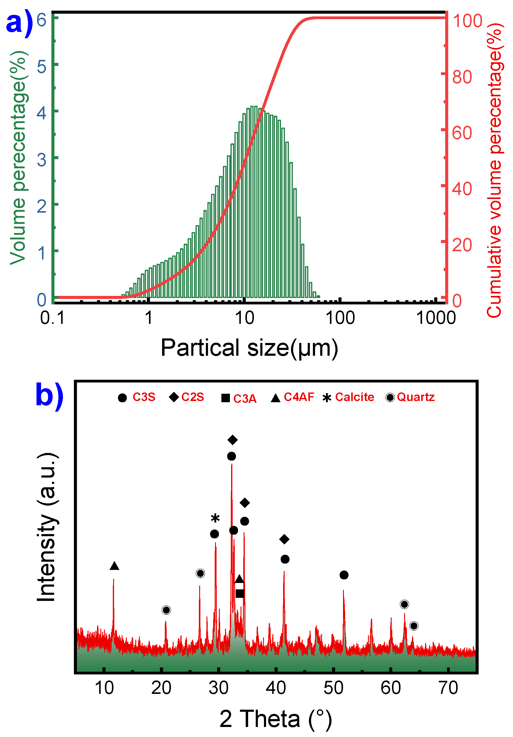
Table 2.
Proportions of base grouting material.
| Marterials | OPC | Water Reducer | Expansive Agent | Defoamer | Cellulose ether | Silica fume |
|---|---|---|---|---|---|---|
| Proportions | 79.67% | 0.14% | 0.18% | 0.006% | 0.004% | 20.0% |
2.2. Mix proportion
Table 3 presents the mix proportions of the tested grouting material components used in the frost heaving stress tests. The preparation method for the grouting material is as follows: 1) Accurately weigh each raw material and add them to the mixer for dry blending for 30 seconds until uniform; 2) Slowly add approximately 70% of the mixing water and stir at a low speed for 60 seconds until a uniform slurry is obtained; 3) Add the remaining mixing water in a second step and stir at high speed for 360 seconds, with the mixer blade speed exceeding 1000 rad/min; 4) After completion of mixing, a fresh slurry is extracted for experimental testing.
Table 3.
Proportions of the tested grouting material.
| Mix NO. | Water cement ratio | Calcium formate (%) | Sulphoaluminate cement (%) | Air-entraining agent (%) | Carbamide (%) |
|---|---|---|---|---|---|
| WC01 | 0.24 | 0 | 0 | 0 | 0 |
| WC02 | 0.26 | 0 | 0 | 0 | 0 |
| WC03 | 0.28 | 0 | 0 | 0 | 0 |
| WC04 | 0.30 | 0 | 0 | 0 | 0 |
| WC05 | 0.32 | 0 | 0 | 0 | 0 |
| CF01 | 0.30 | 0 | 0 | 0 | 0 |
| CF02 | 0.30 | 1.0 | 0 | 0 | 0 |
| CF03 | 0.30 | 2.0 | 0 | 0 | 0 |
| CF04 | 0.30 | 3.0 | 0 | 0 | 0 |
| CF05 | 0.30 | 4.0 | 0 | 0 | 0 |
| CS01 | 0.30 | 0 | 0 | 0 | 0 |
| CS02 | 0.30 | 0 | 5.0 | 0 | 0 |
| CS03 | 0.30 | 0 | 10.0 | 0 | 0 |
| CS04 | 0.30 | 0 | 15.0 | 0 | 0 |
| CS05 | 0.30 | 0 | 20.0 | 0 | 0 |
| AE01 | 0.30 | 0 | 0 | 0 | 0 |
| AE02 | 0.30 | 0 | 0 | 0.1 | 0 |
| AE03 | 0.30 | 0 | 0 | 0.2 | 0 |
| AE04 | 0.30 | 0 | 0 | 0.3 | 0 |
| AE05 | 0.30 | 0 | 0 | 0.4 | 0 |
| CB01 | 0.30 | 0 | 0 | 0 | 0 |
| CB02 | 0.30 | 0 | 0 | 0 | 0.5 |
| CB03 | 0.30 | 0 | 0 | 0 | 1.0 |
| CB04 | 0.30 | 0 | 0 | 0 | 1.5 |
| CB05 | 0.30 | 0 | 0 | 0 | 2.0 |
| CA01 | 0.30 | 0 | 0 | 0 | 0 |
| CA02 | 0.30 | 0.5 | 2.5 | 0.05 | 0.25 |
| CA03 | 0.30 | 1.0 | 5.0 | 0.1 | 0.5 |
| CA04 | 0.30 | 1.5 | 7.5 | 0.15 | 0.75 |
| CA05 | 0.30 | 2.0 | 10.0 | 0.2 | 1.0 |
2.3. Experimental setup
The procedure for testing grout materials is as follows: Grout materials were prepared in two different environments, one at a constant temperature of 25 °C and the other at a constant temperature of 5 °C. After the preparation, fresh slurry was used for initial flowability testing, followed by a flow ability test after a 30min resting period. Subsequent tests included standard setting time, low-temperature setting time, standard compressive strength, low-temperature compressive strength, free water content, and low-temperature frost heaving stress testing. Flowability tests were carried out using a cone flowability tester with a volume of 1725±5ml, and the compressive strength tests were conducted on standard specimens measuring 40mm×40mm×160mm. Standard strength test specimens were cured in a standard temperature and humidity environment and tested after 28 days of immersion in water. Freeze-thaw cycle strength test specimens were cured for 24 hours at 5 °C, subjected to six freeze-thaw cycles in a chamber (-15 ℃ (24 h)~15 ℃ (24 h)), and then cured in a standard temperature and humidity environment for 28 days before testing.
The free water content test was conducted using low-temperature strength test specimens, with the following testing procedure: within the half-hour preceding the commencement of each freeze-thaw cycle, a small sample was extracted from the core of the test block. After fracturing, the sample was soaked in acetone solution for 24 hours to extract the internal free water. Subsequently, it was subjected to vacuum low-temperature drying for 4 hours. A measured sample was then placed in a muffle furnace at 500 °C and incinerated for 4 hours to determine the crystalline water content through weight loss. The free water content was subsequently calculated by subtracting the crystalline water content from the total mixing water.
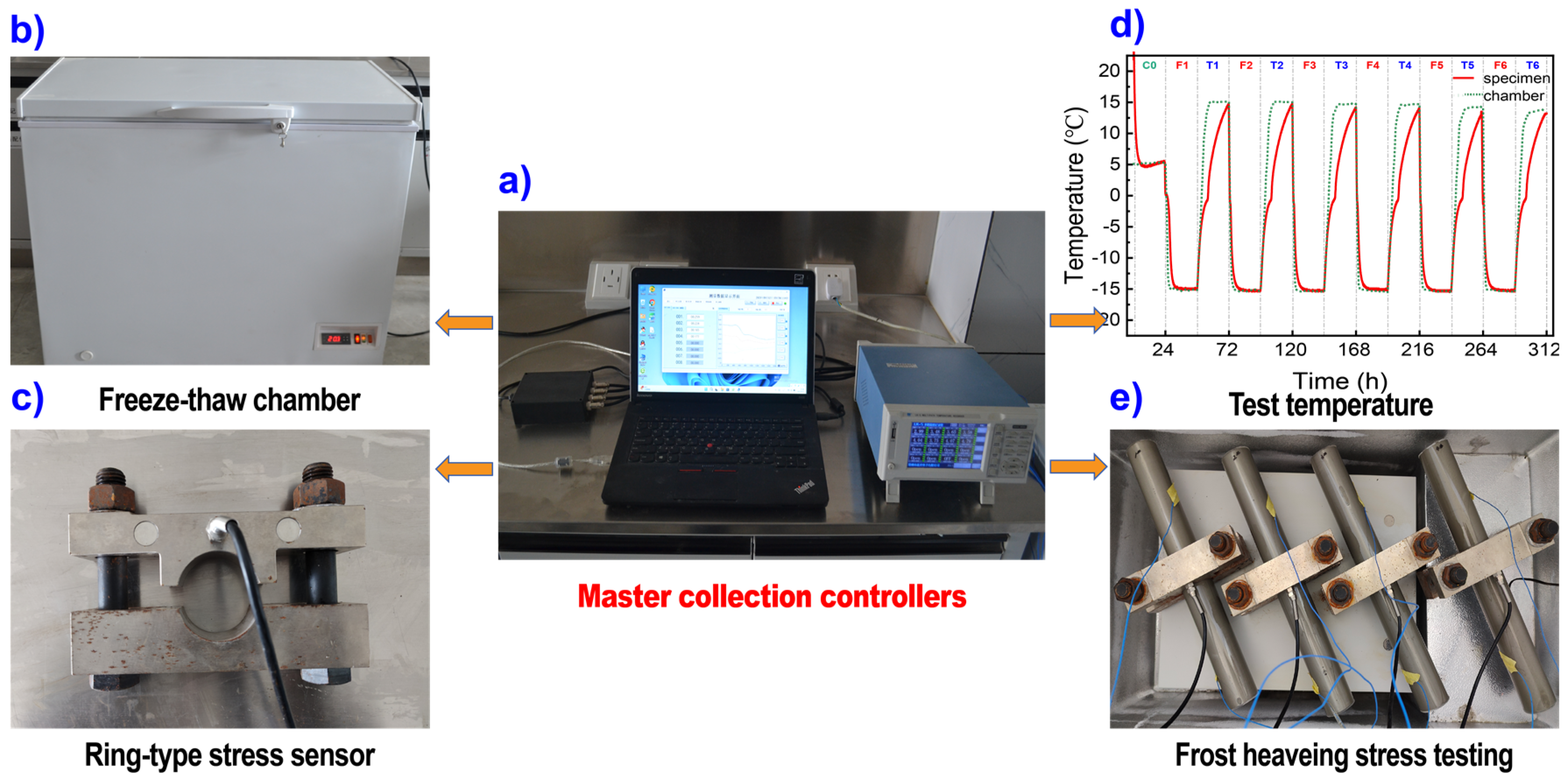
The low-temperature frost heaving stress tests were carried out using a specially designed testing setup comprising a ring-type stress sensor, sample tubing, temperature sensors, freeze-thaw chamber, and a set of master collection controllers, as depicted in Figure 2. The process for conducting low-temperature frost heaving stress tests proceeded as follows: Fresh grout slurry was introduced into the sample tubing and placed within the ring-type load cell, where the initial stress was set at 700±10N by adjusting the securing bolts. Subsequently, the frost heaving stress testing apparatus was positioned inside the low-temperature freeze-thaw chamber and subjected to a 24-hour curing period at 5 °C. Following this, a freeze-thaw cycle (-15 ℃ (24 h)~15 ℃ (24 h)) was initiated, with real-time monitoring of frost heaving stress in the grout materials.
Figure 2.
frost heaving stress test of the grout materials.
3. Results
3.1. Effect of water cement ratio on frost heaving stress
The trends in low-temperature frost heaving stress for grout materials with different water-cement ratios under freeze-thaw cycling conditions, as depicted in Figure 3a, demonstrate that as the grout materials transition from room temperature to a 5 °C low-temperature curing phase, frost heaving stress rapidly decreases and remains stable. This behavior can be attributed to the volumetric contraction of the grout material when it shifts from room temperature to a lower temperature, resulting in a reduction and stabilization of frost heaving stress. The graph reveals that all grout materials, regardless of water-cement ratio, exhibit initially high frost heaving stress during the first cycle. Grout materials with lower water-cement ratios experience a substantial reduction in frost heaving stress and enter a negative stress pattern (the frost heaving stress after freezing is less than that after thawing) after a limited number of freeze-thaw cycles. Specifically, for water-cement ratios of 0.24, 0.26, 0.28, and 0.30, the duration of frost heaving is 1, 2, 3, and 4 cycles, respectively. However, with a water-cement ratio of 0.32, the grout material consistently maintains high frost heaving stress and an extended duration of frost heaving, even retaining relatively high frost heaving stress during the 6th freeze-thaw cycle. The trends in setting time and free water content variations in the grout material (as depicted in Figure 3c) demonstrate a significant correlation between both setting time and free water content at different stages of freeze-thaw cycles with the water-cement ratio.
Additionally, there is a positive relationship between the free water content at various stages of freeze-thaw cycles and the frost heaving pressure, with higher free water content associated with greater frost heaving stress. Notably, when the free water content in the grout material falls below the critical threshold (approximately 11.5%), the stress mode transitions to a negative stress pattern. These observations can be explained by several primary factors. As the water-cement ratio increases, the spacing between solid particles in the grout material widens, the setting rate slows down, and defects in hydration products become more prominent. Consequently, this leads to extended setting times and increased free water content in the grout material. Under the influence of freeze-thaw cycles, both the initial cycle maximum frost heaving stress (σ1-max) and the duration of frost heaving cycles (Td) exhibit an increasing trend. However, Figure 3d also reveals that as the water-cement ratio decreases, the fluidity of the grout material declines, particularly with a significant decrease in the 30-minute fluidity. When the water-cement ratio reaches 0.26, both the 30-minute standard fluidity and low-temperature fluidity of the grout material exceed 30 seconds, making it difficult to carry out normal grouting construction.
Moreover, the results also indicate a clear downward trend in both the standard strength of the grout materials and the compressive strength after freeze-thaw cycles (as Figure 3e shows) with an increasing water-cement ratio. However, the decrease in compressive strength after freeze-thaw cycles is more pronounced compared to the standard compressive strength. Notably, when the water-cement ratio reaches 0.32, there is a significant drop in compressive strength after freeze-thaw cycles, with the residual compressive strength falling to less than one-third of the standard strength. Figure 3f provides insight into the composition of the final hydration products of the grout materials, which predominantly consist of a significant amount of calcium hydroxide(CH), a certain quantity of ettringite, C-S-H, and a small amount of mullite. Increasing the water-cement ratio does not lead to the formation of new crystalline phases in these hydration products, and except for a slight decrease in the intensity of the C-S-H peak, there are minimal changes in other crystalline phases. Additionally, Figure 3g reveals optical and SEM images after freeze-thaw cycles, showing the emergence of numerous micro and macro cracks in the hydration products of the grout materials. As the water-cement ratio increases, both the number and width of these cracks intensify, serving as a primary reason for the accelerated decline in compressive strength after freeze-thaw cycles. Furthermore, the frost heaving stress curve indicates that the residual frost heaving stress in the grout material is slightly higher than the initial stress and cannot fully return to the initial stress level. This effect is particularly pronounced when the water-cement ratio reaches 0.32, and as freeze-thaw cycles progress, the residual frost heaving stress exhibits a linear growth trend, closely related to cracking in the grout material induced by freeze-thaw cycles.
Figure 3.
Effect of water cement ratio on frost heaving stress.
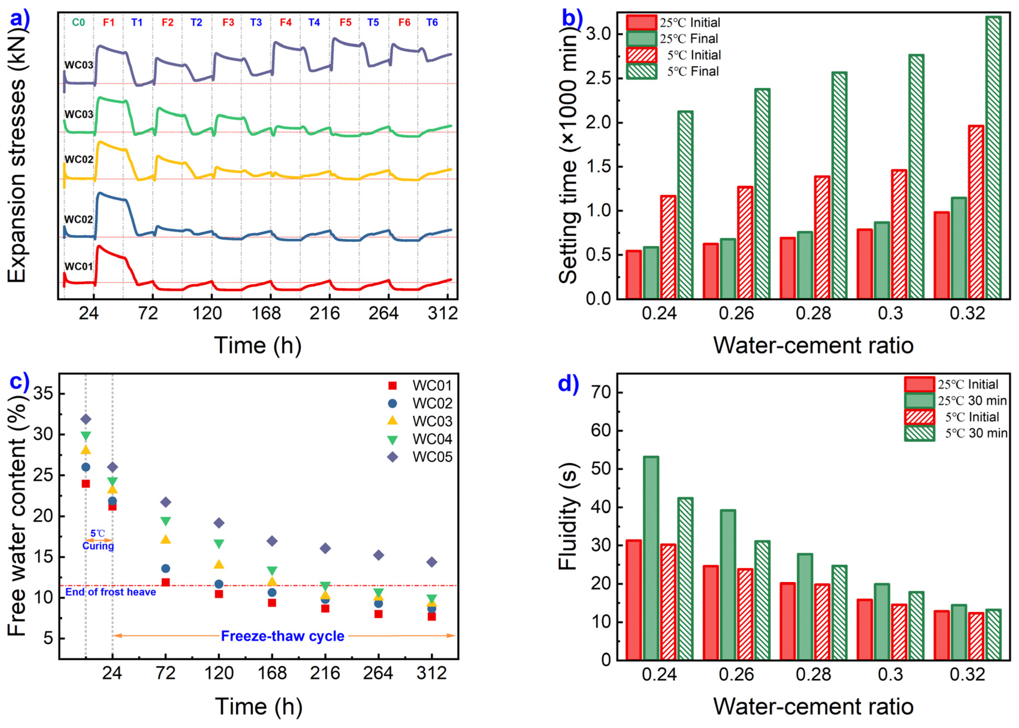
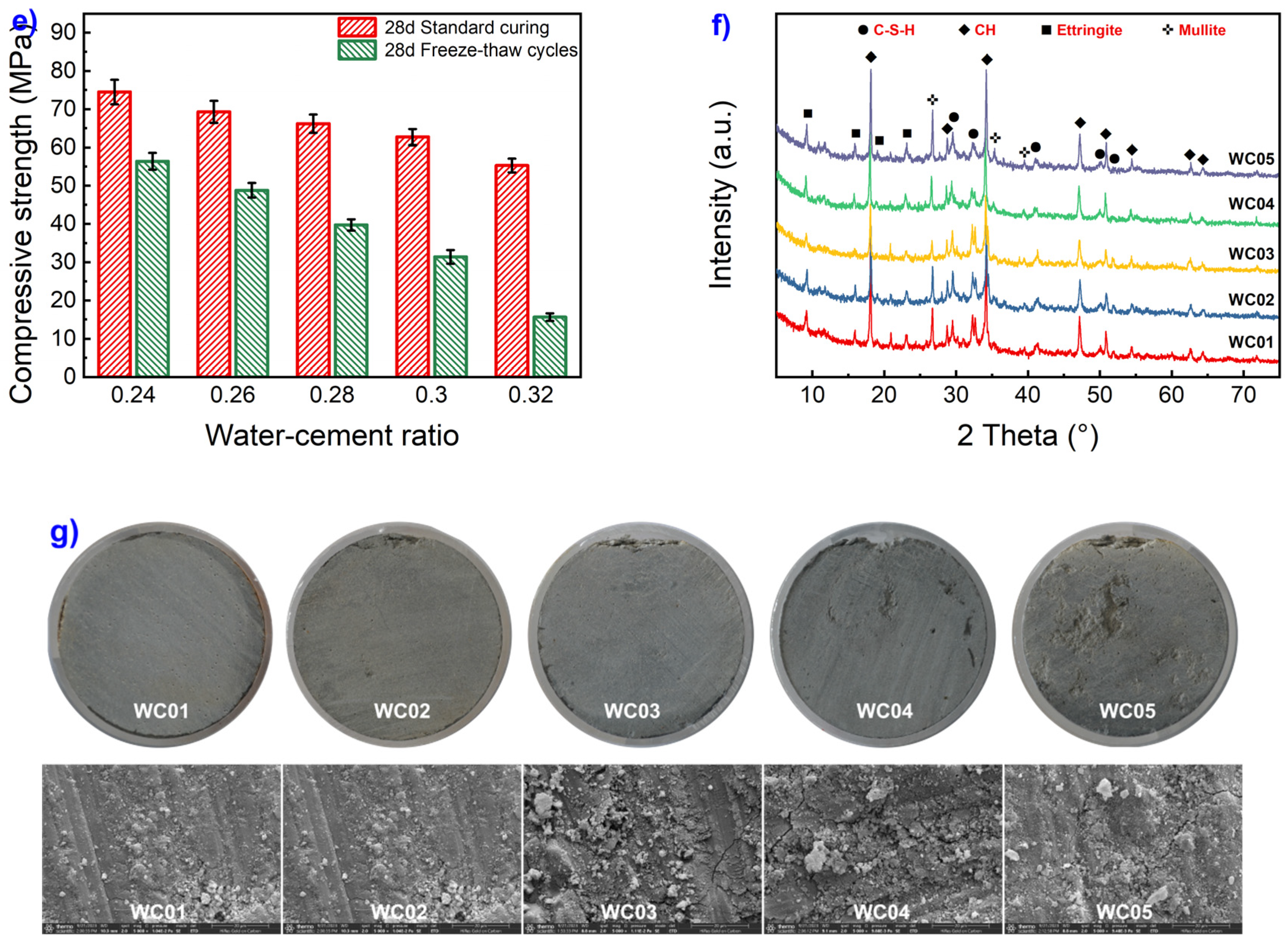
Figure 4 demonstrate 2 characteristic patterns of frost heaving stress: the freeze-expansion/thaw-shrink pattern (FETS pattern, as Figure 4a shows) and the freeze-shrink/thaw-expansion pattern (FSTE pattern, as Figure 4b shows). In the FETS pattern, during the initial freezing phase, frost heaving stress undergoes a brief linear decrease followed by a rapid linear increase until it peaks. It then transitions into a slow, nonlinear growth before gradually declining linearly until the freezing process concludes. During the melting phase, frost heaving stress experiences a transient logarithmic increase followed by a rapid linear decrease. After reaching its peak, it transitions into a slow increase until the melting process concludes. Analyzing the temperature fluctuations in the environmental chamber and specimen surface (as shown in Figure 2d), these patterns are primarily a result of the grout material’s gradual linear contraction due to rapid cooling from 5 °C, causing a brief linear decrease in frost heaving stress. Upon reaching the freezing point, the coupled effect of free water freezing expansion and grout material shrinkage leads to near-linear growth in frost heaving stress. Once the pipe temperature stabilizes, the nearly complete crystallization of free water results in a slowed, nonlinear growth in frost heaving stress. Upon reaching its peak, the continued freezing induces slight shrinkage in the grout material, accompanied by a linear decrease in frost heaving stress. As the environmental temperature rises, rapid melting of ice crystals leads to gradual volume recovery in the grout material, resulting in a rapid linear decrease in frost heaving stress. Upon returning to normal temperature, accelerated hydration reactions in the grout material cause slight volume expansion and a minor increase in pipeline stress.
Figure 4.
Two characteristic frost heaving stress patterns.
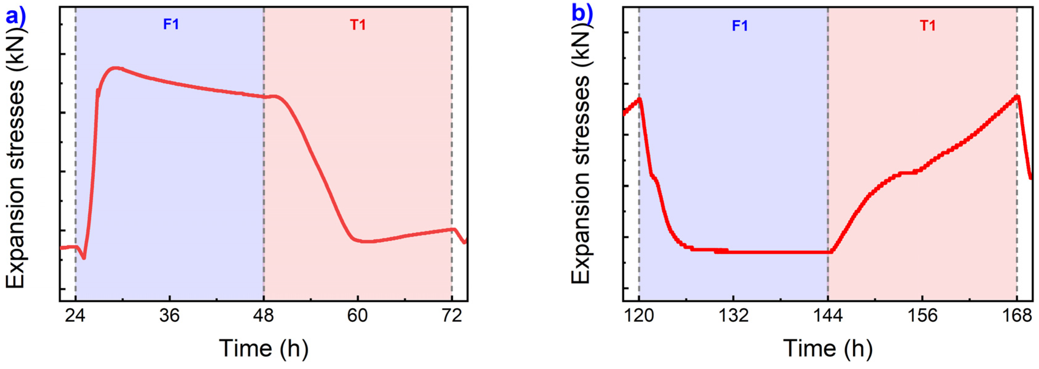
The distinctive features of the FSTE pattern can be outlined as follows: during the freezing process, the frost heaving stress undergoes a two-stage rapid reduction. The first stage is characterized by a linear decrease, followed by a second stage of nonlinear reduction, reaching a peak and maintaining stability until the freezing process concludes. Once the thawing process begins, the frost heaving stress exhibits a three-stage rapid increase. The first stage involves linear growth, followed by a second stage of nonlinear growth, and finally, a third stage of linear growth persists until the end of the thawing process. The primary rationale behind this model can be explained as follows: when the free water content in the grout material decreases to the frost expansion threshold, the grout material gradually contracts as it cools, resulting in a linear decrease in frost heaving pressure. When the ambient temperature drops below the freezing point of free water, the coupling of the expansion caused by the freezing of free water and the contraction due to the cooling of the grout material leads to nonlinear volume contraction, accompanied by a corresponding decrease in frost heaving stress. Once the temperature stabilizes, the volume of the grout material remains constant, and the expansion pressure also remains stable until the freezing process’s conclusion. Upon the initiation of the warming process, the grout material containing ice expands linearly as the temperature rises, resulting in a linear increase in frost heaving stress. Once the temperature surpasses the freezing point, the coupling of the contraction induced by the melting of free water and the expansion due to the warming of the grout material leads to nonlinear expansion (accompanied by a corresponding nonlinear increase in frost heaving stress). After the complete melting of free water, the grout material expands linearly as the temperature continues to rise, accompanied by a corresponding linear increase in frost heaving stress.
3.2. Effect of calcium formate on frost heaving stress
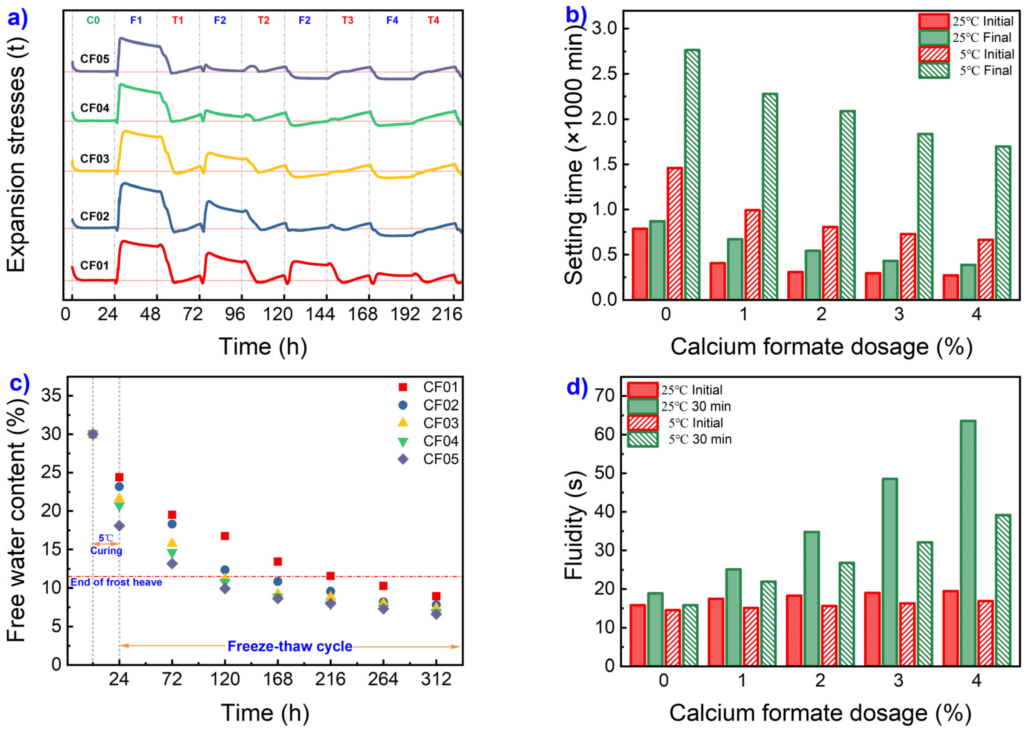
As Figure 5a illustrates, the addition of calcium formate can effectively reduce the initial maximum frost heaving stress of the grout material and shorten the duration of frost heaving cycles (Td). When the calcium formate content is at or below 0.3%, the first and second frost-thaw cycles exhibit a typical FETS pattern, while the third frost-thaw cycle follows a typical freezing-shrinking-frosting pattern. However, when the calcium formate content reaches 0.4%, only the initial low-temperature frost heaving stress curve adheres to the freezing-shrinking pattern. The second low-temperature frost heaving stress curve remains stable with frost heaving stress approaching zero, and subsequent frost-thaw cycles adopt a typical FSTE pattern, with frost heaving stress becoming negative stress pattern.
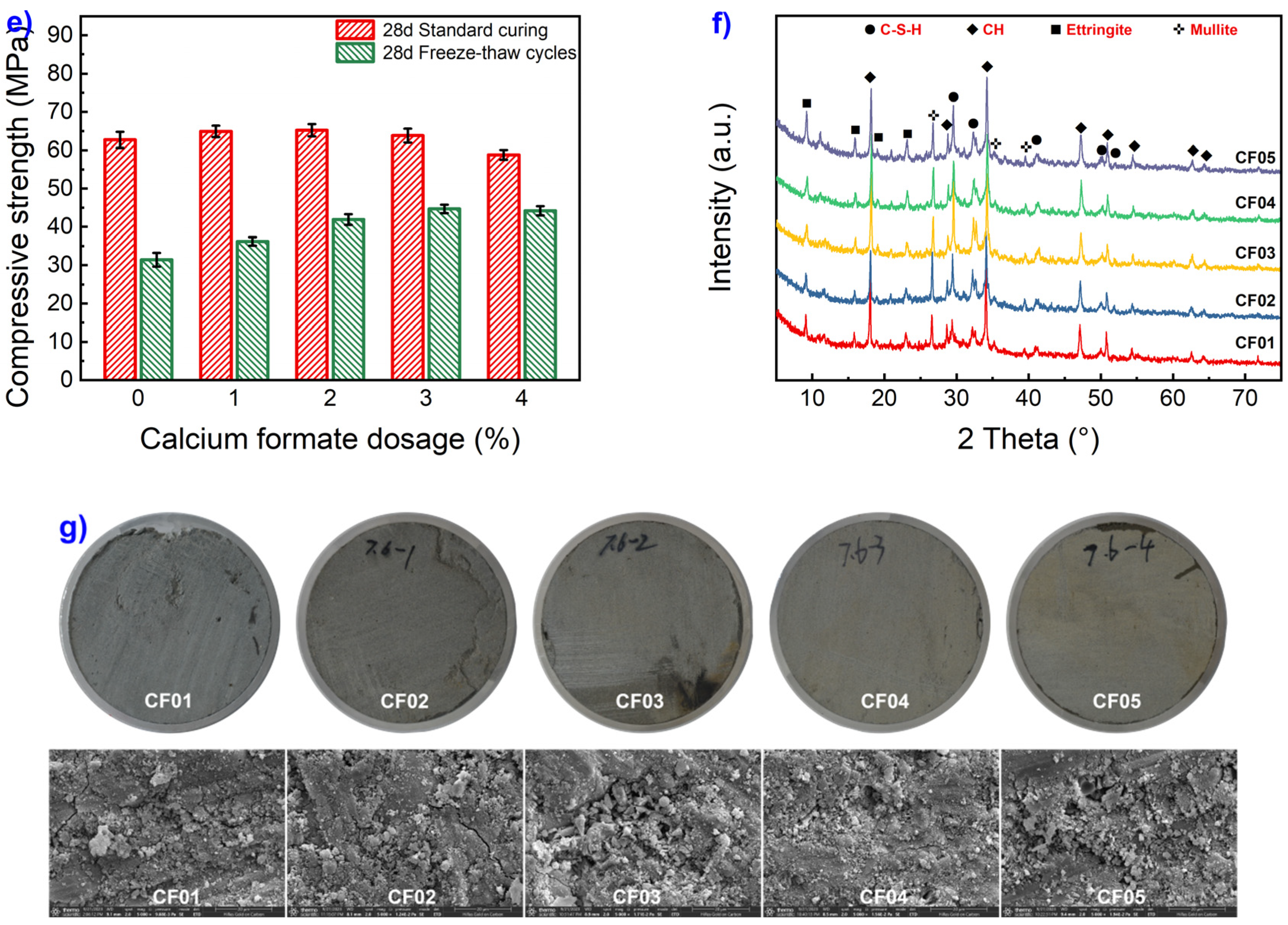
From Figure 5b and Figure 5c, it is apparent that the incorporation of calcium formate into the grout material effectively reduces both ambient and low-temperature setting times. Notably, it significantly shortens the initial setting time of the grout material. Additionally, it has a moderating effect on the free water content within the grout material, with setting time and free water content gradually decreasing as the calcium formate content increases. As shown in Figure 5d, an increase in calcium formate content leads to a slight reduction in the initial flowability of the grout material, with a substantial decline observed at the 30-minute mark. Importantly, when the calcium formate content reaches 3%, the 30-minute low-temperature flowability consistently exceeds 30 seconds. In Figure 5e, it is demonstrated that increasing calcium formate content results in gradual improvements in both the standard and low-temperature compressive strength of the grout material. The standard compressive strength reaches its peak at 2% calcium formate content, while the freeze-thaw cycle compressive strength peaks at 3% calcium formate content. Analyzing the XRD spectra of the grout material after freeze-thaw cycling in Figure 3f, it becomes apparent that the addition of calcium formate leads to a significant increase in the crystalline phases of C-S-H and ettringite, with no new crystalline phases formed. Furthermore, as shown in Figure 5g, an increase in calcium formate content corresponds to a reduction in the quantity, width, and damaged areas of internal cracks within the grout material. This signifies a notable attenuation of freeze-thaw damage, which is a direct consequence of the enhanced compressive strength observed with higher calcium formate content. These phenomena primarily result from the introduction of calcium formate, which raises the concentration of Ca2+ ions in the liquid phase, accelerating the dissolution rate of C-S-H. Simultaneously, a substantial quantity of HCOO- is introduced, and due to its faster diffusion rate compared to Ca2+, HCOO- penetrates the hydration layers of C3S and C2S, speeding up the precipitation of Ca(OH)2 and the decomposition of calcium silicate [25]. This, in turn, promotes the formation of C-S-H and ettringite. Furthermore, HCOO- can chemically react to further cross-link adjacent silicate groups, facilitating the formation of C-S-H gel [26,27]. The combined effect of the high concentration of Ca2+ and HCOO- accelerates the participation of free water in hydration reactions, enhances early strength development, and reduces the susceptibility of the grout material to freezing.
Figure 5.
Effect of calcium formate on frost heaving stress.
3.3. Effect of sulphoaluminate cement on frost heaving stress
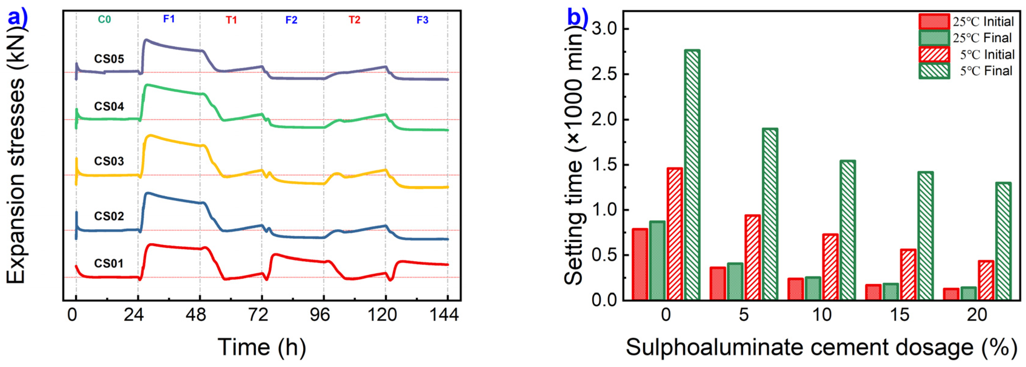
The incorporation of sulphoaluminate cement(SAC), as depicted in Figure 6a, is observed to effectively reduce the frost heaving duration of the grout material. Following the initial cycle, all specimens transitioned from a frost heaving-shrinking mode to a freezing-shrinking-frosting mode. The maximum frost heaving stress during the first cycle exhibited a decreasing trend with increasing SAC content. In Figure 6b, it is evident that the addition of SAC in the grout material significantly shortens the setting time, with a gradual reduction in setting time corresponding to higher levels of cement addition. Figure 6c illustrates a comparison of free water content during various cycles, it becomes apparent that the incorporation of SAC into the grout material also leads to a significant reduction in free water content during each cycling period. After the initial freeze-thaw cycle, the free water content in all dosage levels of the grout material decreases to the frost heaving threshold or below. Additionally, Figure 6d reveals a slight enhancement in initial fluidity with increasing SAC content. However, at SAC content equal to or exceeding 10%, the fluidity drastically declines after 30 minutes at low temperatures, exceeding 30 seconds. Due to the loss of plasticity, grout materials lose their flowability, rendering them unsuitable for grouting applications.
Figure 6.
Effect of sulphoaluminate cement on frost heaving stress.
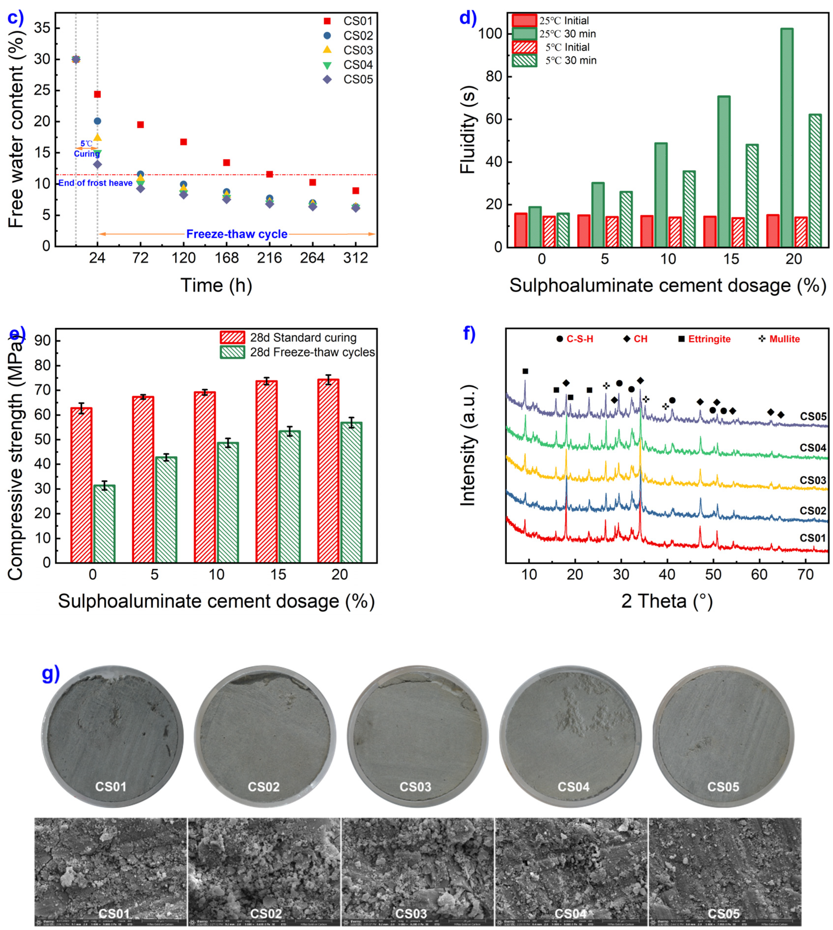
The primary factor contributing to the aforementioned phenomena is the incorporation of SAC into the grout material, which introduces a significant quantity of anhydrous calcium sulfoaluminate. This compound rapidly consumes a substantial portion of free water, promoting the rapid hydration of the grout material and the production of a considerable amount of ettringite. As a consequence, early strength development in the grout material is accelerated. In the later stages of hydration, both types of cement mutually facilitate the formation of denser hydrated compounds, resulting in improved mechanical strength [28,29]. Additionally, the rapid hydration reaction of SAC generates a substantial amount of heat [29], which can expedite the rate of hydration reactions in the grout material, particularly when the ambient temperature returns to normal.
3.4. Effect of air-entraining agents on frost heaving stress
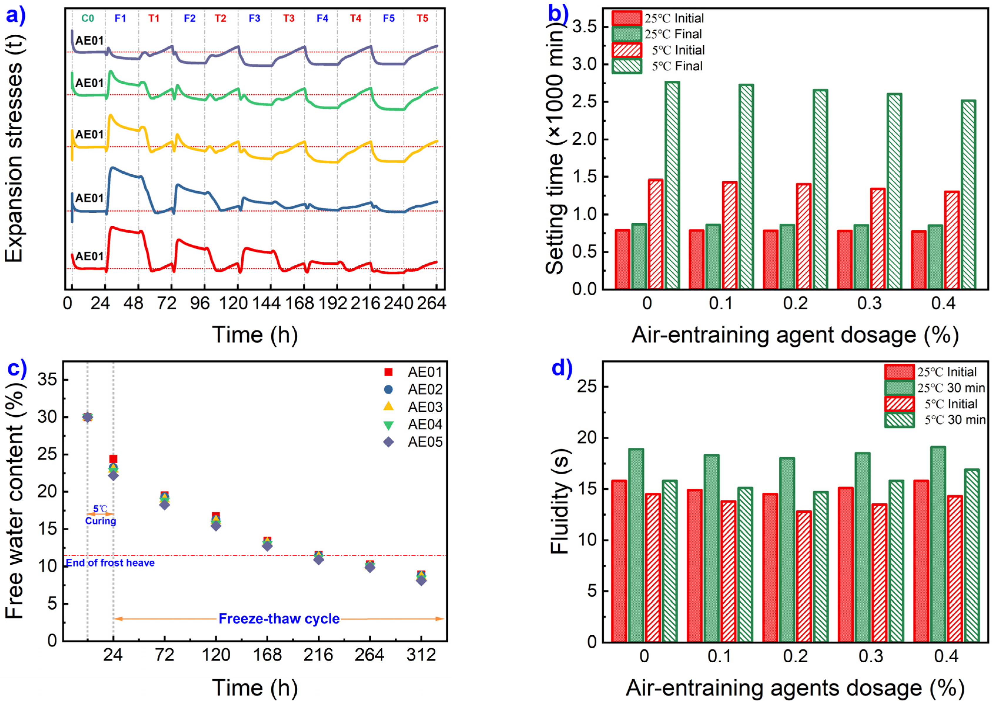
Figure 7a depicts the changing pattern of frost heaving stress in air-entrained grout materials under low-temperature conditions. The graph unequivocally illustrates that the addition of air-entraining agents results in a notable decrease in both the the initial cycle maximum frost heaving stress (σ1-max) and the duration of frost heaving cycles (Td) in the grout material. The frost heaving stress model exhibits distinct the FETS pattern and the FSTE pattern. Specifically, when the air-entraining agent content is 0.05%, the initial maximum frost heaving stress measures 2.50kN, and the frost heaving cycle occurs three times. With a progressive increase in the air-entraining agent content, the initial maximum frost heaving stress experiences a gradual and substantial reduction, accompanied by a decrease in the frost heaving cycle. For instance, at an air-entraining agent content of 0.20%, the initial maximum frost heaving stress diminishes to a mere 0.05kN, and the frost heaving cycle occurs only once.
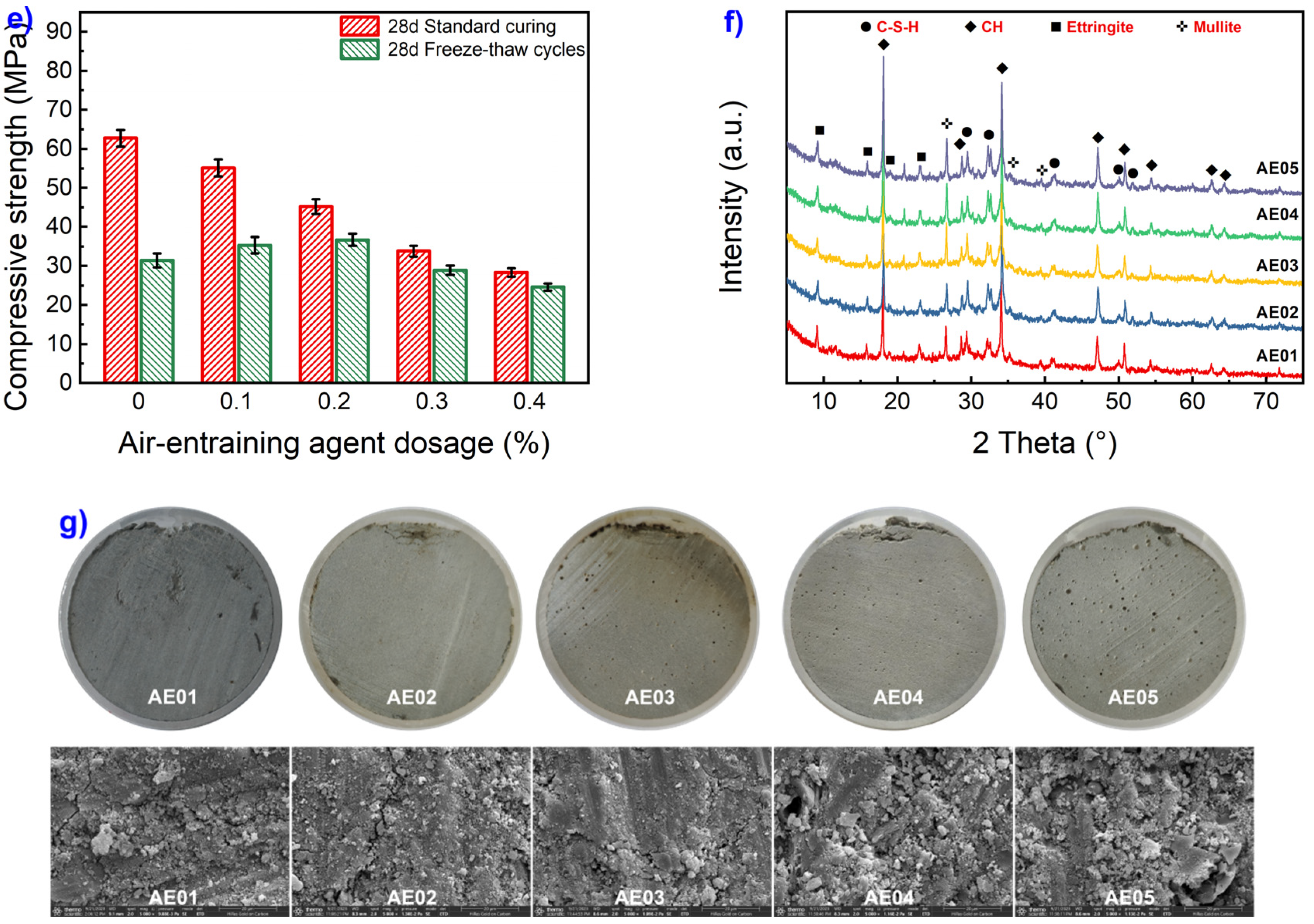
By comparing the experimental results of free water content at various stages (as Figure 7b shows) and the setting time of grout materials (as Figure 7c shows), it becomes evident that the inclusion of an air-entraining agent does not exert a significant influence on these parameters. Additionally, Figure 7d illustrates that the impact of the air-entraining agent on grout materials is relatively minor, with flowability showing a trend of initial reduction followed by an increase as the agent dosage increases. As depicted in Figure 7e, the introduction of an air-entraining agent gradually diminishes the mechanical strength of the materials under standard curing conditions. However, under freeze-thaw cycling conditions, a moderate amount of air-entraining agent can enhance the mechanical strength of the grout materials to a certain extent. Nonetheless, when the dosage of the air-entraining agent surpasses 0.2%, the compressive strength of the grout materials experiences rapid deterioration during freeze-thaw cycling. Figure 7f reveals that the air-entraining agent has no discernible impact on the crystalline phase composition of hydration products in grout materials, with minimal changes in the content of CH, C-S-H, and ettringite. However, examination of macro/microscopic images of grout materials (as Figure 7g shows) demonstrates a significant influence of the air-entraining agent on the macrostructure of the hydration products. With an increase in the air-entraining agent dosage, the formation of macroscopically visible closed air voids within the grout materials increases, while macroscopic damage areas, macroscopic cracks, and the number and width of microscopic cracks decrease. This phenomenon can be primarily attributed to the introduction of a substantial volume of structurally stable, fine, and persistent bubbles by the air-entraining agent in the grout materials. These bubbles serve to mitigate the volume expansion occurring during free water crystallization, alleviate freeze-thaw pressures, and reduce structural damage, thereby mitigating the adverse effects of freeze-thaw cycling on the structure and strength of grout materials [30,31,32,33,34].
Figure 7.
Effect of air-entraining agents on frost heaving stress.
3.5. Effect of carbamide on frost heaving stress
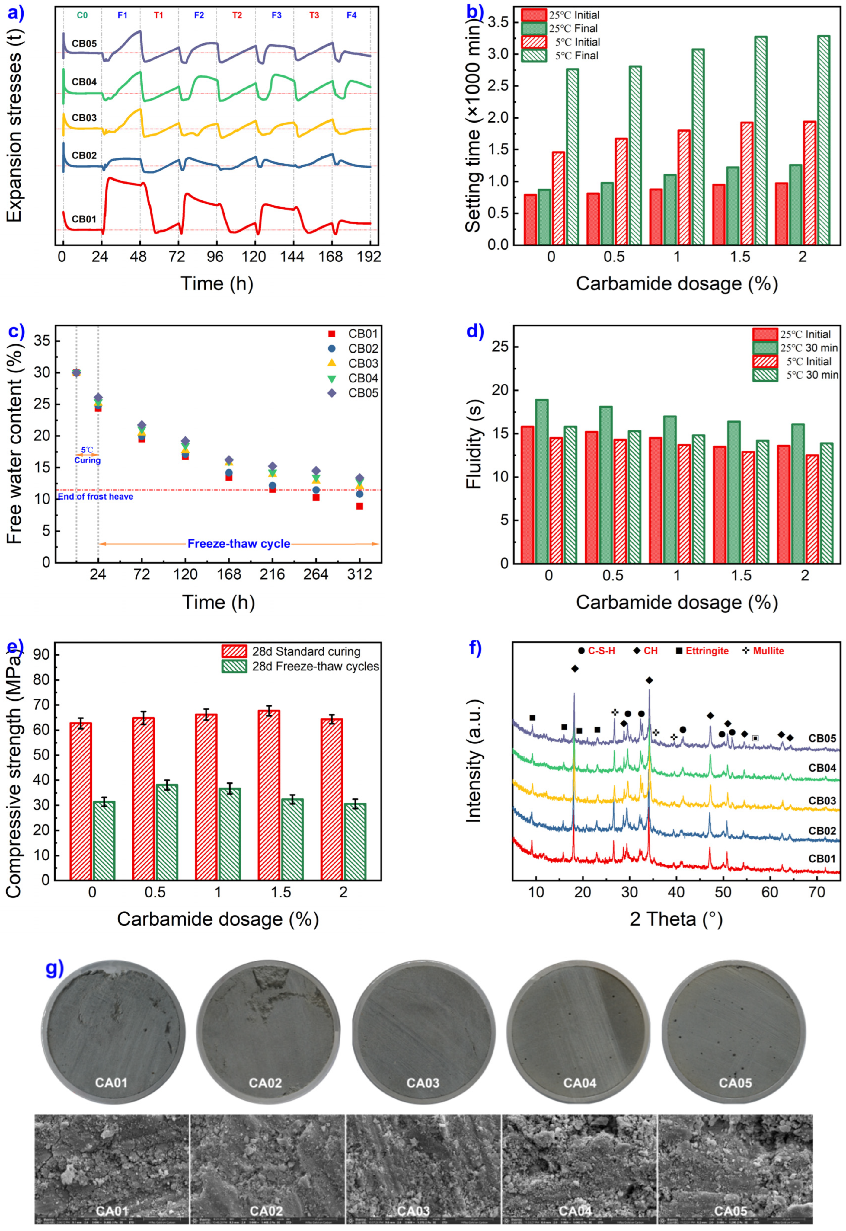
The trend of frost heaving stress variation in carbamide-added grout materials under low-temperature conditions is depicted in Figure 8a. The graph clearly illustrates that the addition of carbamide significantly reduces frost heaving stress during the freeze-thaw cycles. At a carbamide content of 0.1%, the change in frost heaving stress under low-temperature freeze-thaw cycles follows a pattern similar to the typical FETS pattern. However, with the introduction of carbamide, the initial frost heaving stress in the grout material increases slowly during the early freezing stages, reaching a minimal value, and experiences rapid attenuation during the early melting phases. As the carbamide content further increases, the heterogeneity in frost heaving stress during the grout material’s freezing stages intensifies. The first maximum frost heaving stress gradually grows, and the duration of frost heaving extends. When the carbamide content surpasses 0.2%, the initial frost heaving stress exhibits a linear growth pattern, reaching peak upon the first freezing termination. It continues to follow the frost-expansion even after three consecutive freeze-thaw cycles, and the frost-thaw stress difference diminishes with the elongation of the freeze-thaw cycles. From Figure 8b and Figure 8c, it is evident that incorporating carbamide into the grout material does not accelerate the setting time or reduce free water content. On the contrary, the addition of carbamide leads to an increase in both setting time and free water content as the carbamide content rises. The results of flowability tests for carbamide-added grout materials (Figure 8d) show a slight improvement in flowability after the addition of carbamide, although the overall impact is relatively minor.
As illustrated in Figure 8e, the standard compressive strength of the grout material shows a marginal increase with the introduction of carbamide. The peak compressive strength is reached at a carbamide content of 1.5%. However, under the influence of freeze-thaw cycles, the compressive strength reaches its maximum at a carbamide content of 0.5%, gradually declining as the carbamide content continues to rise. From the XRD patterns in Figure 8f), it is evident that the hydration products within the grout material undergo some changes with the incorporation of carbamide. The peak intensity of C-S-H exhibits a moderate increase with increasing carbamide content, and new product phases appear around 2θ=56°. Figure 8g provides macroscopic and microscopic images of the grout material, indicating that the addition of a small quantity of carbamide results in a reduction in both the number and width of macro and micro cracks, as well as a decrease in the level of damage. However, as the carbamide content increases further, the number and width of cracks expand, and the degree of damage intensifies. Simultaneously, the inclusion of carbamide within the grout material leads to the formation of visible macroscopic closed pores.
Figure 8.
Effect of carbamide on frost heaving stress.
In contrast to the above characteristic patterns, the introduction of carbamide led to a distinctive alteration in frost heaving stress, characterized by two heteromorphosis patterns: linear growth pattern (LG pattern, as shown in Figure 9a) and non-linear growth pattern (NLG pattern, as illustrated in Figure 9b). The NLG pattern closely resembled the freeze-thaw expansion-shrinkage model. Its distinctive features were as follows: during the initial freezing phase, frost heaving stress displayed a noticeable linear decrease until reaching a nadir, followed by a rapid non-linear growth until it peaked. Subsequently, the stress exhibited a gradual decline until the freezing process concluded. During the thawing stage, frost heaving stress rapidly decreased in a linear manner initially, transforming into a slow linear growth until the thawing process concluded. These patterns were correlated with the temperature fluctuations in the environmental chamber and the surface temperature of the pipeline, as depicted in Figure 2d. The primary reasons for these patterns were as follows: the grout material experienced rapid cooling, causing contraction and resulting in continuous linear reduction of frost heaving stress. When the temperature of the grout material dropped below freezing, the combination of freezing expansion of free water and the grout material’s contraction due to freezing led to non-linear continuous growth of frost heaving stress, reaching its peak after complete crystallization of free water. Subsequently, due to continuous freezing of the grout material, volume contraction occurred until the freezing stage ended. As the temperature rose, rapid melting of ice crystals ensued, gradually restoring the grout material’s volume. carbamide facilitated faster ice crystal melting, leading to a swift linear decline in frost heaving stress. After complete ice crystal melting, the material underwent accelerated hydration reactions, causing volume expansion and resulting in slow linear growth of frost heaving stress.
Figure 9.
Two heteromorphosis frost heaving stress patterns.
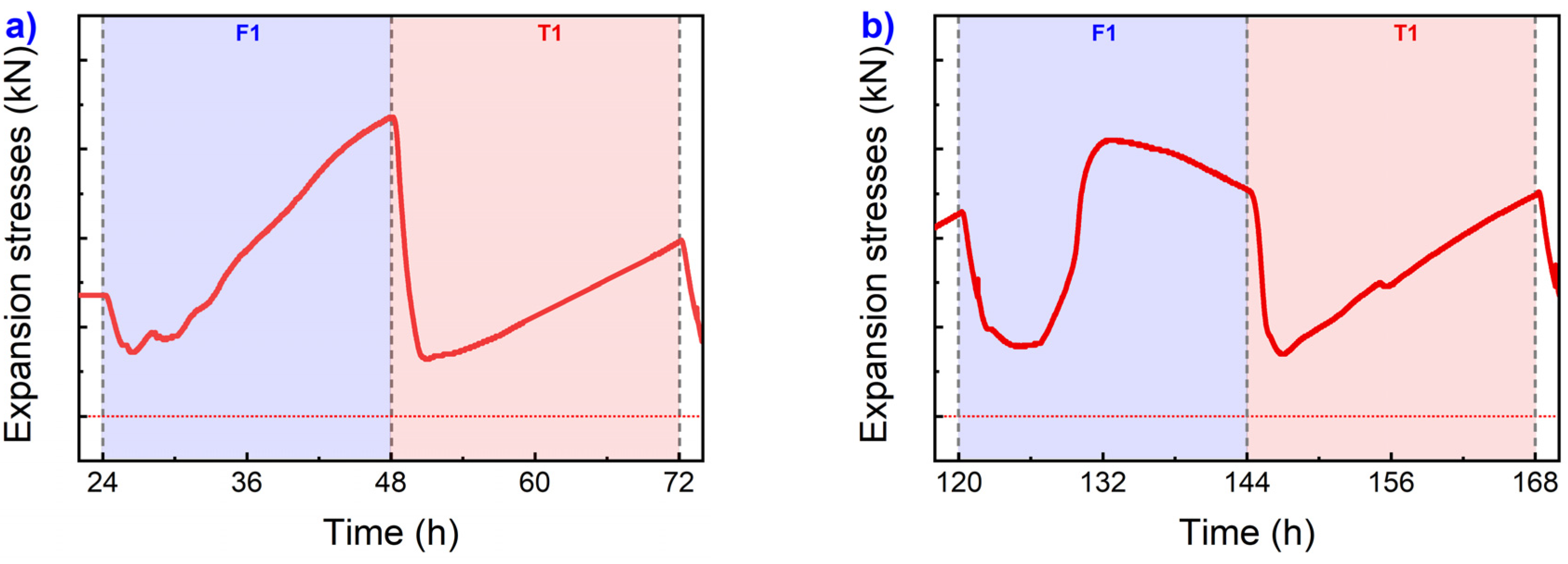
The characteristics of the LG pattern are as follows: at the beginning of the freezing process, there is a noticeable linear decrease in frost heaving stress, succeeded by a rapid linear increase until the freezing process concludes. During the thawing process, frost heaving stress experiences an extremely rapid linear decline, reaching a peak before transitioning into a slow linear increase until the thawing process concludes. These patterns are observed in conjunction with the temperature variation curves of the environmental chamber and pipeline surface (as shown in Figure 8d). The primary factors driving this behavior include the grout material’s gradual rapid cooling from 5℃, leading to contraction and a distinct linear decrease in frost heaving stress. As the grout material’s temperature drops below freezing, frost heaving occurs due to the expansion caused by the freezing of free water, combined with the grout material’s freezing-induced contraction. The intensification of the freezing process results in a continuous linear increase in frost heaving stress until the freezing stage concludes. This phenomenon is attributed to the high carbamide content, which delays setting time, increases free water content, lowers the freezing point of free water, and decelerates free water crystallization. Upon warming, ice crystals melt rapidly, leading to gradual volume recovery of the grout material and a swift linear decrease in frost heaving stress. Once the ice crystals within the grout material completely melt, resulting in the lowest volume contraction, frost heaving stress peaks. Subsequently, accelerated hydration reactions due to complete thawing and self-heating result in slow volume expansion, leading to a gradual linear increase in frost heaving stress.
3.6. Effect of compound agents on frost heaving stress
As demonstrated in the preceding five sections of this paper, it is evident that reducing the water-to-cement ratio or incorporating additives like calcium formate and sulfoaluminate cement can partially reduce the frost heaving stress and frost heaving duration of grout materials under freeze-thaw cycling conditions. However, due to their distinct mechanisms of action, achieving the desired comprehensive performance for grout materials in construction remains challenging. Therefore, in this section, we adopt a combined approach involving calcium formate, sulfoaluminate cement, carbamide, and air-entraining agents to enhance grout materials. Detailed experimental results are presented in the subsequent sections.
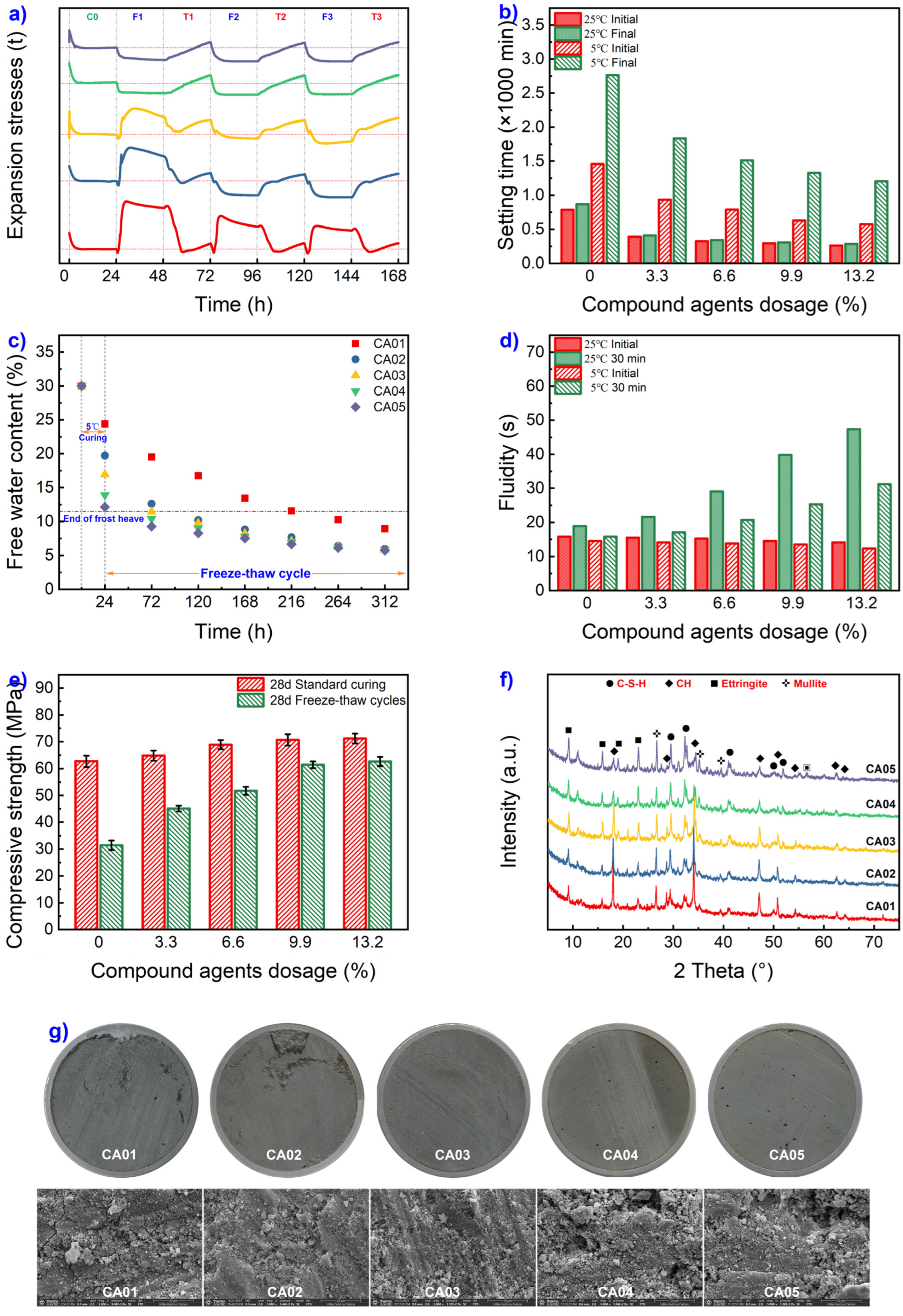
Figure 10a illustrates the variation trend of frost heaving stress in grout materials containing composite additives under low-temperature conditions. The graph clearly demonstrates that the incorporation of composite additives effectively reduces both the initial cycle maximum frost heaving stress (σ1-max) and the duration of frost heaving cycles (Td) in the grout material. With lower admixture content, the grout material exhibits a frost heaving pattern only during the initial freeze-thaw cycle. However, the maximum frost heaving stress during this cycle significantly diminishes compared to the blank sample, accompanied by a distinct deformation in its stress pattern. When the composite additive content reaches 9.9%, the grout material experiences no frost heaving stress during the initial freeze-thaw cycle.
Figure 10b,c reveal that the introduction of composite additives leads to effective reductions in low-temperature setting time and free water content in the grout material, owing to the combined effects of calcium formate and sulfoaluminate cement. At composite additive contents of 9.9% and 13.2%, the co-action of carbamide and air-entraining agents transforms the frost heaving stress pattern into a freeze-shrink-thaw mode, even when the free water content in the grout material exceeds the critical moisture level before the initial freeze-thaw cycle. Figure 10d shows that the incorporation of composite additives also diminishes the flowability of the grout material. When the content reaches 13.2%, the 30-minute low-temperature flowability slightly exceeds 30 seconds, but the grout material in this state still complies with the requirements for grouting construction. Figure 10e indicates that the addition of composite additives results in a gradual increase in the standard compressive strength of the grout material, with a substantial improvement in compressive strength after freeze-thaw cycles. At a composite additive content of 9.9%, the residual strength after freeze-thaw cycles exceeds 85%. From the XRD spectra of hydration products in Figure 10f, it can be observed that with an increase in composite additive content, the content of ettringite and C-S-H in the grout material’s hydration products significantly increases, while the content of calcium hydroxide (CH) decreases. Additionally, as the composite additive content rises, new phase products (around 2θ=56°) also form in the hydration products. Figure 10g reveals that under the influence of freeze-thaw cycles, an increase in composite additive content leads to a reduction in macroscopic/microscopic cracks within the grout material, decreased structural damage, and an increase in the number of macroscopic pores. In summary, compared to other singly modified grout materials, composite additives demonstrate superior freeze resistance even at lower contents due to the combined effects of calcium formate, sulfoaluminate cement for early strength and rapid setting, air-entraining agents for freeze-thaw resistance, and carbamide for reducing the crystallization point of ice. At a content of 9.9%, composite additives can already exhibit a negative frost heaving stress pattern during the initial freeze-thaw cycle.
Figure 10.
Effect of composite additives on frost heaving stress.
4. Conclusions
The purpose of this paper is to investigate the frost heaving characteristics of grout materials under freeze-thaw cycles, understand the influence and mechanisms of water-cement ratio and additives on frost heaving properties, and provide a scientific basis for selecting low-temperature grout materials in seasonally frozen regions. The aim is to mitigate frost heaving risks and enhance bridge quality assurance. Through frost heaving stress tests, free water content analysis, XRD, and SEM experiments, this study explores the effects of water-cement ratio and various additives on the variation characteristics of frost heaving stress in grout materials under freeze-thaw cycles. It delves into the mechanisms behind the improvement of frost heaving properties concerning water-cement ratio and different additives, proposing an approach that employs compound admixtures to enhance frost heaving characteristics of grout materials. The paper draws the following key conclusions:
1) Free water content is a critical indicator influencing the development of frost heaving stress in grout materials under freeze-thaw cycles. When no freezing point depressant additive is added, the critical free water content is approximately 11.5%. With the addition of freezing point depressant additives, the critical free water content increases.
2) Lowering the water-cement ratio and incorporating calcium formate, sulfoaluminate cement, air-entraining agents, and carbamide can reduce the initial cycle maximum frost heaving stress (σ1-max) and the duration of frost heaving cycles (Td) in grout materials to some extent. However, due to different mechanisms, solely reducing the water-cement ratio or adding a single type of additive is insufficient to effectively alter frost heaving characteristics while meeting comprehensive performance criteria.
3) The mechanism behind the addition of calcium formate and sulfoaluminate cement is to promote hydration, accelerate setting, and reduce free water content. Incorporating air-entraining agents introduces numerous tiny bubbles, dispersing frost heaving stress. The addition of carbamide primarily reduces the freezing point of free water, delaying frost heaving, and simultaneously disperses frost heaving stress due to its air-entraining effect.
4) Using composite admixtures containing calcium formate, sulfoaluminate cement, carbamide, and air-entraining agents can effectively improve the initial cycle frost heaving stress and the duration of frost heaving in grout materials under freeze-thaw conditions. These admixtures also maintain high flowability, strength, and pumpability. When the admixture content is 9.9%, the initial frost heaving stress during the first freeze-thaw cycle is completely eliminated, and other comprehensive performance parameters meet the requirements for grouting applications.
Author Contributions
Conceptualization, Yongfeng Wei; Data curation, Jiangtao Gao and Run Su; Formal analysis, Hui Dou; Funding acquisition, Yongfeng Wei; Investigation, Run Su; Methodology, Run Su and Shengjun Ma; Resources, Hui Dou; Software, Yongfeng Wei, Hui Dou and Shengjun Ma; Supervision, Yongfeng Wei; Validation, Yongfeng Wei, Jiangtao Gao and Shengjun Ma; Visualization, Yongfeng Wei and Hui Dou; Writing—original draft, Yongfeng Wei and Hui Dou; Writing—review & editing, Yongfeng Wei. All authors will be informed about each step of manuscript processing including submission, revision, revision reminder, etc. via emails from our system or assigned Assistant Editor.
Funding
This work was supported by the Key research and development project of Gansu Province (21YF11GA009), the Fund Project of Youth Science and Technology of Gansu Provincial(23JRRA1475), the Major Projects of the Science and Technology Plan of Gansu Province (21ZD4GA001), and the Industrial Support Plan for Colleges and Universities of Gansu Province(2022CYZ-02).
Institutional Review Board Statement
Not applicable.
Informed Consent Statement
Not applicable.
Data Availability Statement
Not applicable.
Conflicts of Interest
The authors declare no conflict of interest, financial or otherwise.
References
- Chatterji, S. Freezing of Air-Entrained Cement-Based Materials and Specific Actions of Air-Entraining Agents. Cement and Concrete Composites 2003, 25, 759–765. [Google Scholar] [CrossRef]
- Dahmani, L.; Khenane, A.; Kaci, S. Behavior of the Reinforced Concrete at Cryogenic Temperatures. Cryogenics 2007, 47, 517–525. [Google Scholar] [CrossRef]
- Demirboğa, R.; Karagöl, F.; Polat, R.; Kaygusuz, M.A. The Effects of Urea On Strength Gaining of Fresh Concrete Under the Cold Weather Conditions. Constr. Build. Mater. 2014, 64, 114–120. [Google Scholar] [CrossRef]
- Du, L.; Folliard, K.J. Mechanisms of Air Entrainment in Concrete. Cement Concrete Res. 2005, 35, 1463–1471. [Google Scholar] [CrossRef]
- Fagerlund, G. The International Cooperative Test of the Critical Degree of Saturation Method of Assessing the Freeze/Thaw Resistance of Concrete. Mater. Struct. 1977, 10, 231–253. [Google Scholar] [CrossRef]
- Garg, S.; Misra, S. Efficiency of NDT Techniques to Detect Voids in Grouted Post-Tensioned Concrete Ducts. Nondestruct. Test. Eva. 2021, 36, 366–387. [Google Scholar] [CrossRef]
- Gong, C.; Zhou, X.; Dai, W.; Liu, Y.; Lu, L.; Cheng, X. Effects of Carbamide On Fluidity and Setting Time of Sulphoaluminate Cement and Properties of Planting Concrete From Sulphoaluminate Cement. Constr. Build. Mater. 2018, 182, 290–297. [Google Scholar] [CrossRef]
- Gopinathan, S.; Anand, K.B. Properties of Cement Grout Modified with Ultra-Fine Slag. Frontiers of Structural and Civil Engineering 2018, 12, 58–66. [Google Scholar] [CrossRef]
- Heikal, M. Effect of Calcium Formate as an Accelerator On the Physicochemical and Mechanical Properties of Pozzolanic Cement Pastes. Cement Concrete Res. 2004, 34, 1051–1056. [Google Scholar] [CrossRef]
- Huang, Q.; Zhou, X.; Zhuang, L.; Gong, C.; Lu, L.; Fu, X. Effects of Carbamide On Sulfoaluminate Cement Paste for Growing Plants. Constr. Build. Mater. 2016, 113, 229–236. [Google Scholar] [CrossRef]
- Institution, P.T., Specification for Grouting of Post-Tensioned Structures., 2003.
- Minh, H., H. Mutsuyoshi and K. Niitani, Influence of grouting condition on crack and load-carrying capacity of post-tensioned concrete beam due to chloride-induced corrosion. Construction and Building Materials 2007, 21, 1568–1575. [Google Scholar] [CrossRef]
- Karagol, F.; Demirboga, R.; Khushefati, W.H. Behavior of Fresh and Hardened Concretes with Antifreeze Admixtures in Deep-Freeze Low Temperatures and Exterior Winter Conditions. Constr. Build. Mater. 2015, 76, 388–395. [Google Scholar] [CrossRef]
- Kaufmann, J.P. Experimental Identification of Ice Formation in Small Concrete Pores. Cement Concrete Res. 2004, 34, 1421–1427. [Google Scholar] [CrossRef]
- Ke, G.; Zhang, J.; Tian, B.; Wang, J. Characteristic Analysis of Concrete Air Entraining Agents in Different Media. Cement Concrete Res. 2020, 135, 106142. [Google Scholar] [CrossRef]
- Kotwa, A. Influence of Sub-Zero Temperature and Initial Set Time On the Properties of Hardened Concrete. Structure and Environment 2011, 3, 11–17. [Google Scholar]
- Mehta, P.K.; Monteiro, P.J.M. Concrete Microstructure Properties and Materials, 3 ed.; McGraw-Hill Companies, 2006. [Google Scholar]
- Mohan, M.K.; Pillai, R.G.; Santhanam, M.; Gettu, R. High-Performance Cementitious Grout with Fly Ash for Corrosion Protection of Post-Tensioned Concrete Structures. Constr. Build. Mater. 2021, 281, 122612. [Google Scholar] [CrossRef]
- Pelletier-Chaignat, L.; Winnefeld, F.; Lothenbach, B.; Müller, C.J. Beneficial Use of Limestone Filler with Calcium Sulphoaluminate Cement. Constr. Build. Mater. 2012, 26, 619–627. [Google Scholar] [CrossRef]
- Permeh, S.; Lau, K.; Tansel, B. Moisture and Ion Mobilization and Stratification in Post-Tensioned (PT) Grout During Hydration. Case Studies in Construction Materials 2021, 15, e00644. [Google Scholar] [CrossRef]
- Powers, T.C. A Working Hypothesis for Further Studies of Frost Resistance of Concrete. Journal Proceedings 1945, 41, 245–272. [Google Scholar]
- Powers, T.C.; Helmuth, R.A. Theory of Volume Changes in Hardened Portland-Cement Paste During Freezing. Highway research board proceedings 1953, 32, 285–297. [Google Scholar]
- Radhakrishna; Trejo, D.; Gardoni, P.; Hueste, M.B.D.; Reinschmidt, K. Time-Variant Flexural Reliability of Posttensioned, Segmental Concrete Bridges Exposed to Corrosive Environments. American Society of Civil Engineers 2014, A4014018.
- Sagüés, A.; Powers, R.G.; Wang, H. Mechanism of Corrosion of Steel Strands in Post Tensioned Grouteda Ssemblies. Corrosion 2003, 03312. [Google Scholar]
- Setzer, M.J. Micro-Ice-Lens Formation in Porous Solid. J. Colloid Interf. Sci. 2001, 243, 193–201. [Google Scholar] [CrossRef]
- Shannag, M.J. High-Performance Cementitious Grouts for Structural Repair. Cement Concrete Res. 2002, 32, 803–808. [Google Scholar] [CrossRef]
- Tan, H.; Zhang, X.; He, X.; Guo, Y.; Deng, X.; Su, Y.; Yang, J.; Wang, Y. Utilization of Lithium Slag by Wet-Grinding Process to Improve the Early Strength of Sulphoaluminate Cement Paste. J. Clean. Prod. 2018. [Google Scholar] [CrossRef]
- Val, D.V.; Chernin, L.; Stewart, M.G. Experimental and Numerical Investigation of Corrosion-Induced Cover Cracking in Reinforced Concrete Structures. Journal of structural engineering (New York, N.Y.) 2009, 135, 376–385. [Google Scholar] [CrossRef]
- Vatin, N.I.; Barabanshchikov, Y.G.; Komarinskiy, M.V.; Smirnov, S.I. Modification of the Cast Concrete Mixture by Air-Entraining Agents. Magazine of Civil Engineering 2015, 56, 3–10. [Google Scholar] [CrossRef]
- Wang, L.; Dai, L.; Bian, H.; Ma, Y.; Zhang, J. Concrete Cracking Prediction Under Combined Prestress and Strand Corrosion. Struct. Infrastruct. E. 2018, 15, 285–295. [Google Scholar] [CrossRef]
- Wang, L.; Ju, S.; Chu, H.; Liu, Z.; Yang, Z.; Wang, F.; Jiang, J. Hydration Process and Microstructure Evolution of Low Exothermic Concrete Produced with Urea. Constr. Build. Mater. 2020, 248, 118640. [Google Scholar] [CrossRef]
- Wang, Y.; Jia, J.; Cao, Q.; Gao, X. Effect of Calcium Formate On the Compressive Strength, and Hydration Process of Cement Composite Containing Fly Ash and Slag. Journal of Building Engineering 2022, 50, 104133. [Google Scholar] [CrossRef]
- Wang, Y.; Wu, J.; Pu, H. Effect of Calcium Formate as an Accelerator On Dilatancy Deformation, Strength and Microstructure of Cemented Tailings Backfill. Chemosphere 2022, 291, 132710. [Google Scholar] [CrossRef]
- Yang, Q.; Zhu, P.; Wu, X.; Huang, S. Properties of Concrete with a New Type of Saponin Air-Entraining Agent. Cement Concrete Res. 2000, 30, 1313–1317. [Google Scholar] [CrossRef]
- Yoo, D.; Ryu, G.; Yuan, T.; Koh, K.; Yoon, Y.; ASCE, M. Cracking Behavior of Posttensioning Grout with Various Strand-to-Duct Area Ratios. American Society of Civil 2014, 04014197. [Google Scholar] [CrossRef]
- Yuan, D.; Jiang, W.; Sha, A.; Xiao, J.; Wu, W.; Wang, T. Technology Method and Functional Characteristics of Road Thermoelectric Generator System Based On Seebeck Effect. Appl. Energ. 2023, 331, 120459. [Google Scholar] [CrossRef]
- Zapata-Padilla, J.R.; Juárez-Alvarado, C.A.; Durán-Herrera, A.; Baltazar-Zamora, M.A.; Terán-Torres, B.T.; Vázquez-Leal, F.R.; Mendoza-Rangel, J.M. Portland Cement-Based Grouts Enhanced with Basalt Fibers for Post-Tensioned Concrete Duct Filling. Materials 2023, 16, 2842. [Google Scholar] [CrossRef]
- Zhao, Y.X.; Jin, W.L. Modeling the Amount of Steel Corrosion at the Cracking of Concrete Cover. Adv. Struct. Eng. 2006, 9, 687–696. [Google Scholar] [CrossRef]
Disclaimer/Publisher’s Note: The statements, opinions and data contained in all publications are solely those of the individual author(s) and contributor(s) and not of MDPI and/or the editor(s). MDPI and/or the editor(s) disclaim responsibility for any injury to people or property resulting from any ideas, methods, instructions or products referred to in the content. |
© 2023 by the authors. Licensee MDPI, Basel, Switzerland. This article is an open access article distributed under the terms and conditions of the Creative Commons Attribution (CC BY) license (http://creativecommons.org/licenses/by/4.0/).
Copyright: This open access article is published under a Creative Commons CC BY 4.0 license, which permit the free download, distribution, and reuse, provided that the author and preprint are cited in any reuse.


