
Submitted:
13 October 2023
Posted:
13 October 2023
You are already at the latest version
Abstract
This article presents the possibilities of using ferrite absorption material for shielding rooms with medical devices in order to additionally protect them against the limits of the electric component of the E field, which are up to 61 V/m. These values may appear in connection with the currently launched 5G system operating in the high-band frequency range, i.e. 28 GHz and 38 GHz, and may cause negative effects on the operation of medical devices. The possibilities of using ferrite absorption material for shielding rooms with medical devices were determined based on the results of measurements of the electrical properties of the ferrite material performed using two methods: the reflection method and the free space method. In the article, the complex electrical permittivity and complex magnetic permeability were determined for a ferrite plate based on measurements of the reflection coefficient and the transmission (attenuation) coefficient. The presented calculation and measurement results were used to show the properties of the ferrite material in the frequency range from 15 GHz to 45 GHz and to show the possibility of using it for shielding rooms as a material absorbing electromagnetic waves in this frequency range.
Keywords:
ferrite
; absorber
; permittivity
; permeability
; open coaxial probe method
; free space method
1. Introduction
Absorbers in the RF/microwave field are materials that attenuate electromagnetic wave energy. Absorbers are used in a wide range of applications to eliminate scattered or unwanted radiation that could interfere with system operation. Absorbers can take a variety of physical forms, including flexible elastomers, foam, rigid epoxy, or plastics. They can be made to withstand extreme weather conditions and temperatures. Absorbers have become a critical component of some systems, reducing interference between circuit elements [1,2].
Absorbers can be used externally to reduce reflection or transmission to individual objects, but they can also be used internally to reduce oscillations caused by cavity resonance. They can also be used to recreate a free space environment by eliminating reflections in an anechoic chamber. Creating shielded rooms is particularly important when it comes to ensuring safety, e.g. during medical or scientific research. Shielded rooms are used to protect against electromagnetic interference, which can interfere with the operation of medical and scientific equipment. They can also be used to protect against external interference, such as external sources of electrical power or other sources of interference [1,2].
The best solution is to create a room with two layers of walls, both external and internal. Insulating material should be installed on the outer wall, and the inner wall should be reinforced with a layer of acoustic material. The acoustic layer is able to effectively silence the room, which helps avoid sound disturbances. In addition, it is important that the room is equipped with windows and doors to facilitate access to the interior. The next step in creating a shielded room is to install an anti-interference protection system. Such a system may consist of filters, clamps, connectors, power supplies or other devices that effectively protect medical or scientific equipment from electromagnetic interference. All of these elements should be matched to the specific type of equipment or research to ensure maximum effectiveness. Additionally, it is important that all system components are well installed and properly protected against damage to ensure its durability [1,2,3].
According to the Electromagnetic Compatibility Directive, all medical devices should be resistant to electromagnetic interference with an electric field strength of 9 V/m to 28 V/m depending on the frequency range, and in the case of military applications 200 V/m. In the case of civil applications, these values are too low in relation to the reference levels defined in Recommendation 1999/519/EC, expressed as limits of the intensity of the electric component of the E-field, which are as high as 61 V/m. The presence of electric field strengths higher than 9 - 28 V/m in the environment may cause negative effects on the operation of medical devices. The negative effects of a medical device are obvious and include damage to human health or even death [4,5,6,7].
This article presents the possibilities of using ferrite absorption material for shielding rooms with medical devices in order to additionally protect them against the limits of the electric component of the E field, which are up to 61 V/m. These values may appear in connection with the currently launched 5G system operating in the high-band frequency range, i.e. 28 GHz and 38 GHz, and may cause negative effects on the operation of medical devices.
2. Electrical parameters of absorption materials
Knowledge of the dielectric parameters of materials is essential for microwave or radio engineers in device analysis and synthesis. Relative permittivity, loss factor and conductivity are input parameters for electromagnetic field modeling and simulation. Although for many materials these parameters can be found in tables, it is often necessary to determine them experimentally.
Absorbers typically consist of a filler material inside a material matrix. The filler consists of one or more ingredients. The matrix material is selected for its physical properties (temperature resistance, weather resistance, etc.).
Absorbers are characterized by electrical permittivity and magnetic permeability. Electrical permittivity is a measure of the material's influence on the electric field of an electromagnetic wave, and magnetic permeability is a measure of the material's influence on the magnetic component of the wave. Permittivity is complex and is generally written as [8]:
where ε0 it is the permittivity of free space, and is the complex relative permittivity (dielectrics are very often lossy). The relative permittivity of a dielectric material is defined as the ratio of the capacitance of a capacitor using the material as a dielectric compared to a capacitor of the same size using a vacuum as the medium. The real part and the imaginary part of the complex relative permittivity, i.e. the relative dielectric constant and the dielectric loss coefficient, are the basic physical parameters of dielectric materials. The composite relative permittivity (Complex Dielectric Constant – CDC ) can be given [8]:
The permittivity results from the dielectric polarization of the material. The quantity is sometimes called the dielectric constant, which is somewhat misleading when applied to absorbers because can vary significantly with frequency. The quantity is a measure of the weakening of the electric field caused by the material. The electrical loss tangent of a material is defined as [8]:
As mentioned above, both polarization delay and charge transport induce an electric current flowing in the same phase as the voltage applied to the sample dielectric. This current, called forward current, generates Joule heat or dielectric losses. Therefore, the electrical conductivity σ and the dielectric loss coefficient are mutually correlated and show the following relationship:
where is the real part of the complex relative permittivity, tan(δ) is the loss angle factor and σ is conductivity.
The greater the material loss tangent, the greater is the attenuation of the wave traveling through the material. An analogy to electrical permittivity is magnetic permeability, which is written as
Permeability is a measure of a material's influence on a magnetic field. Both components contribute to wavelength compression within the material. Additionally, due to the coupled electromagnetic wave, the loss of the magnetic or electric field will weaken the energy of the wave.
In most absorbers, both permittivity and transmittance are functions of frequency and can vary significantly even over a small frequency range. If the complex permittivity and permeability in a given frequency range are known, then the effect of the material on the wave is completely known.
3. Measurements of complex permittivity
A common feature of all works in the field of measurement of complex permittivity is a more or less extensive comparison of the dielectric properties of selected materials in order to illustrate the theoretical considerations of the authors.
The measurement of electrical properties includes measurements of complex electrical permeability () and complex magnetic permeability (). The complex value of electric permittivity and magnetic permeability, as already mentioned, consists of a real part and an imaginary part.
There are many methods used to measure the electrical permittivity and magnetic permeability of a material, with each method limited to specific frequencies, materials, applications, etc. The following chapter presents proposed methods for measuring the electrical properties of selected materials:
- −
- transmission-reflection method based on coaxial line,
- −
- method using an open coaxial line (reflection method),
- −
Measurement using the transmission-reflection method involves placing a sample in a waveguide or coaxial line section and measuring complex scattering matrix parameters using two network analyzer (VNA) ports. Before taking a measurement, calibrate the instrument in the required frequency range. The measurement method involves measuring the reflection (S11) and transmission (S21) parameters. Based on these parameters of the scattering matrix, which are closely related to the complex electric and magnetic permeability, the values of these parameters can be determined using appropriate mathematical equations. The conversion of the values of the scattering matrix parameters S into complex parameters of electric and magnetic permeability is most often performed using specialized software. In many cases, this method requires preparing the sample, in a manner similar to machining, so that the sample adheres to the inside of the waveguide or coaxial cable.
Measurement using the open coaxial line method involves placing the measurement probe on the material being tested and measuring the scattering matrix parameters using one port of the network analyzer (VNA). Before taking a measurement, calibrate the instrument in the required frequency range. The measurement method involves measuring the reflection parameter (S11) or admittance Y. Based on the parameter of the scattering matrix or admittance, which is closely related to the complex electrical permittivity, the values of this parameter can be determined using appropriate mathematical equations. The conversion of the values of the scattering matrix parameters S or admittance to complex permittivity parameters is most often performed using specialized software [8,9].
Measurement using the free space method involves placing the sample between two antennas in an appropriate holder and measuring complex scatter matrix parameters using two network analyzer (VNA) ports. Before carrying out the measurement, the instrument should be calibrated in the required frequency range, including the test antennas. The measurement method involves measuring the reflection (S11) and transmission (S21) parameters. Based on these parameters of the scattering matrix, which are closely related to the complex electric and magnetic permeability, the values of these parameters can be determined using appropriate mathematical equations. The conversion of the values of the scattering matrix parameters S into complex parameters of electric and magnetic permeability is most often performed using specialized software [8,9].
4. Assumptions of the research methods
There are several methods for measuring complex permittivity, which were mentioned in the previous section. If we want to use a broadband measurement method that is non-destructive and non-invasive, we should choose the open coaxial line reflection method or the free space method, which are discussed in this article.
4.1. Reflection method
The reflection method involves measuring the reflection coefficient at the interface of two materials, at the open end of the concentric line (as a detector) and on the tested material (Figure 1). This is a well-known method for determining dielectric parameters. This method is based on the fact that the reflection coefficient of an open coaxial line depends on the dielectric parameters of the MUT connected to it. To calculate complex permittivity from the measured reflectance it is useful to use the equivalent perimeter of an open coaxial line [9].
Figure 1 shows the measurement of complex permittivity from the point of view of electromagnetic field theory and electromagnetic wave propagation at the interface between two materials with different impedances. The probe translates changes in MUT (Measurement Under Test) permittivity into changes in the input reflectance of the probe.
The surface of the MUT sample must have perfect contact with the probe. The thickness of the sample to be measured must be at least twice the equivalent depth of penetration of the electromagnetic wave d. This thickness ensures attenuation of reflected waves by approximately -35 dB, which means that their impact on the measured reflection coefficient is insignificant.
The open-end coaxial probe can be modeled as a coaxial waveguide with a semi-infinite flange, as shown in Figure 2. In this figure and in the equations below, a and b are the inner and outer radii of the coaxial hole, so that a < b. The incident principal mode of transverse electric and magnetic (TEM) fields propagates along the waveguide. Near the aperture, the TEM wave becomes distorted and the electric field vector begins to acquire a component perpendicular to the aperture plane [9,10,11]. The energy of the incident wave is partially radiated into the dielectric half-space and partially reflected back to the coaxial waveguide, as shown in Figure 2.
The complex magnitude of the reflected wave depends largely on the dielectric properties of the tested material. Therefore, an open-flange coaxial probe can be used to measure the of a material.
The electromagnetic matching characteristics of an open waveguide probe are the complex reflection coefficient Γ and the normalized input admittance Y. They are connected by the following linear relationship [12]:
To obtain of the tested material, it is necessary to know the dependence of these parameters on The theoretical function Y = Y() can be obtained by solving the boundary problem of wave radiation from a semi-infinite flange waveguide. Such a problem can be solved for a coaxial line. Compared to probes with other waveguide configurations, the coaxial probe enables dielectric measurements at centimeter and millimeter wavelengths, making it convenient and efficient. An approximation of the main TEM mode in a coaxial waveguide with a perfectly conductive flange can be found in the literature. According to these relationships, the integral expression for the normalized input admittance Y can be written as follows [13,14,15]:
where ; ; is the electrical permittivity of the coaxial probe filling; is the wavenumber in free space; and f are the angular and linear frequencies of the microwave signal, respectively; J0(x) is a zero-order Bessel function; and Si(x) is a sine integral.
The full-wave solution of the electromagnetic characteristics of a coaxial probe and the influence of higher-order modes on the input admittance were studied by Pournaropoulos and Misra. They found good agreement between the aperture admittances calculated by the full-wave method and the simple TEM mode solution, indicating that the TEM mode approximation is correct.
If the aperture admittance Y is known from measurements, then (9) becomes a transcendental equation with respect to the unknown . To solve this equation directly, the integral expression in (9) must be evaluated numerically. However, this approach would be computationally expensive to achieve acceptable retrieval accuracy . Therefore, the integral is represented by a power series with respect to the wavenumber k. In practice, a finite number of M terms from this series is assumed [12,16]:
In this equation (10), the coefficients Gm and Cm depend only on the radii of the coaxial probe a and b. Equations for the first few coefficients in this series can be found in the literature. However, general formulations of Gm and Cm for any m are not available in the literature. At the same time, these expressions are crucial to perform analysis over a wide range of frequencies and dielectric constants. Therefore, general equations for the coefficients Gm and Cm have been specially derived as [16]:
We have made sure that the first five Gm coefficients and the first five Cm coefficients calculated from (11) and (12) coincide with the corresponding values reported in the literature. Note that in several publications the input admittance is represented by a triple integral in real coordinate space. However, in this case, calculating the coefficients in the appropriate power series would be much more complicated.
Let us assume that the input admittance Y = Ymeas is known from the measurements. Then the transcendental equation with respect to k can be written as follows [16]:
To solve equation (13), we use the iterative Newton-Raphson method. According to this approach, the solution in the current iteration k(j) can be expressed by the solution in the previous iteration k(j−1) as follows [16]:
To initiate the iterative process (14), a zero-order approximation k(0) must be provided. If we keep terms with the second and fourth powers of k only in (10), we obtain the following biquadratic equation, which can be solved with respect to k(0):
Our analysis shows that satisfactory convergence of the iterative process (14) occurs in four to five iterations for all frequencies and dielectric constants. The true aperture diameter admittance for the sample is obtained from the composite reflectance coefficient S11 measured by the vector network analyzer (VNA). Considering that the cable and connectors represent a linear two-port network between the VNA and the aperture, the composite reflectance S11 of the probe-cable-connectors system is related to the aperture admittance as follows [12,16]:
where A, B i C are complex coefficients related to the structure of the probe. These coefficients can be found using a set of three calibration measurements of three materials with known admittances. For each calibration measurement, the VNA measures the appropriate reflectances (S11)1,2,3. Substituting in (16) with the known values (S11)1,2,3 measured for three selected calibration materials, we obtain a system of equations with respect to A, B and C. Therefore, A, B and C (as functions of frequency) can be found by solving equation (16). These factors must be found for each measurement and are the correction factors needed to determine the admittance of the material being tested.
The method of solving the complex equation (16) consists in breaking it into a real and imaginary part, thus obtaining a system of two real nonlinear equations for two unknowns. To obtain A, B and C, the admittance is measured for three materials with known complex permittivity and then a system of three equations is solved for the unknowns A, B and C. In order to measure complex permittivity of the tested sample, the admittance is measured by measuring the S11 parameter and a system of three equations for the unknown real and imaginary parts is solved.
Based on the above analyses, we can assume that the input admittance of the equivalent circuit can be related to the measured S11 coefficient as [16]:
where Y0 = 1/(50 Ω) = 0,02 S is the characteristic admittance of the probe.
4.2. Free space method
The free space method is used to determine and from the reflection and transmission coefficients of a flat sample. This method is particularly suitable for fast, routine and broadband measurements of and of high-loss materials. For materials with dielectric (or magnetic) loss less than 0.1, loss angle coefficient measurements are inaccurate due to errors in reflection and transmission measurements. The dielectric constant and loss tangent of low-loss materials can be accurately measured using the free space method, which involves measuring the reflectance of a metal-coated sample [17].
In the free-space method, the reflection (S11) and transmission (S21) coefficients of a flat sample for a normally incident plane wave are measured. The complex parameters and are calculated from the measured S11 and S21. For thin and flexible samples of magnetic materials, the measurement accuracy of S11 is low due to the sample sagging when mounted on the sample holder. Such samples are therefore placed between two quartz plates that have half the wavelength in the midband. The actual reflectance and transmittance coefficients S11 and S21, of the sample are calculated from the measured S11 and S21 of the quartz plate-sample-quartz plate assembly based on knowledge of the composite permittivity and thickness of the quartz plates [17].
Figure 3 shows a flat sample of thickness d placed in free space. The complex electric permittivity and the complex magnetic permeability with respect to free space are defined as:
When analyzing the determination of dielectric parameters, it should be assumed that a flat sample has an infinite transverse dimension, so diffraction effects at the edges can be neglected. A linearly polarized, uniform plane wave with frequency is normally incident on the sample. The reflection and transmission coefficients S11 and S21 are measured in free space for a normally incident plane wave. Using the boundary conditions at the air-sample interface (Figure 3), it can be shown that the parameters S11 and S21 are related to the parameters and T using the following equations [18,19,20]:
where is the reflection coefficient at the air and sample boundary and T is the transmission parameter defined by:
where and are the normalized characteristic impedance and propagation constant of the tested sample. They are related to and with the following relationships:
where represents the propagation constant of free space (wave constant), and is the wavelength in free space. Based on equations (20) and (21), we can determine S from the scattering matrix as [21,22] :
where:
In equation (26), the plus or minus sign is selected based on the relationship . Using (23), the complex propagation constant can be written as:
Based on equations (22) and (25), we can determine as a dependency from the reflectance coefficient at the air-sample interface:
Based on equations (24) and (29), we can determine the complex parameters i , depending on the reflectance at the air-sample boundary:
Based on equations (30) and (31), we can express the complex parameters and i as a dependence on the parameters of the scatter matrix S [18,20,21,22]:
where can be expressed:
where n = 0, ±1, ±2, …; and is the normalized characteristic impedance and propagation constant of the tested sample; T - transmission parameter; d - sample thickness.
5. Measuring system
5.1. Reflection method
A typical open coaxial reflection measurement system consists of a network analyzer, a coaxial probe and software. The measurements were made at the laboratory stand whose block diagram and appearance are shown in Figure 4. Measurements were made using the ZVA67 network analyzer and the DAK TL-P system in the frequency range from 15 GHz to 67 GHz.
The coaxial probe shown in Figure 5 is in direct contact with the MUT during the measurement. The measurement of complex permittivity is very fast and takes place in three stages. First, the vector network analyzer is calibrated. Then, calibration is performed using a reference material (with a known dielectric constant εc, most often Teflon). Only after calibration is the MUT reflectivity measured. Complex permittivity MUT determined using a PC (in our case using DAK software).
5.1.1. Measuring probe
For this measurement method, standard 2.92 mm (SMA - SubMiniature version A) and 2.40 mm connectors were used along with a low-loss coaxial cable from Huber&Suchner. The measurement probe can be described by an equivalent circuit consisting of a boundary capacitance between the inner and outer conductors outside the coaxial structure and a radiation conductance that represents the propagation losses. These capacitances and conductivities depend on the frequency and permittivity, and also depend on the dimensions (inner and outer diameter) of the probe [9,10]. The input admittance of the equivalent circuit can be expressed as:
A coaxial probe can be represented as an antenna in a lossy medium with the description:
This means that the admittance of a medium with permittivity at the angular frequency ω is the same as the admittance measured in free space at the frequency - times higher and multiplied by . The input admittance of the coaxial transmission line is then given by [9]:
where Y is the measured impedance of the probe, C0 i G0 are constants determined by the equivalent circuit of the probe in free space. The admittance Y is related to the measured reflectance S11 by the equation [9,10]:
where Y0 = 1/(50 Ω) = 0.02 S is characteristic admittance of the probe.
5.1.2. Calibration Kit and ZVA Calibration
The system is a single-port network, so the measurement is limited only to measuring the input reflectance S11. The OSL (Open, Short and Load) calibration method is performed at the interface between the probe and the MUT sample.
The DAK-TL Calibration Kit comprises a set of thickness gauges that can be used to accurately zero the stage, as well as alumina ( = 9.75), boron nitride ( = 4.40), Teflon ( = 2.07), and Eccostock ( = 2.54) reference discs, as shown in Figure 6. Three standards – Open, Short, and Load – are used to perform the calibration of the DAK-TL probe. The procedure is similar to that used to perform a one port, port extension calibration of a VNA. Via application of the calibration, the reference plane of the S11 measurement is shifted to the probe flange.
5.1.3. Measurement procedure
The procedure for measuring the real part and the imaginary part of the complex relative permittivity, i.e. the relative dielectric constant and the dielectric loss coefficient, is as follows:
- −
- Selection of the measurement frequency range
- −
- Performing calibration for the vector network analyzer. The measurement system is a single-port network, so the measurement is limited only to measuring the input reflectance S11. The VNA calibration method is OSL (Open, Short and Load) calibration, which is performed at the interface between the probe and the tested sample.
- −
- S11 measurement for 3 materials with known complex permittivity’s and determination of correction factors A, B and C on this basis using the (16).
- −
- Measurement of S11 for any desired sample and determination of the admittance based on equation (16). Breaking equation (16) into a real and imaginary part, thus obtaining a system of two real nonlinear equations for two unknowns, the real part and the imaginary of the complex permittivity .
- −
- If necessary, derivation from of any quantities of interest, such as relative permittivity εr, loss factor tan(δ) or conductivity σ from equations (3), (4), (5).
5.2. Free space method
The free space method is one of the measurement methods used to determine the electrical properties of materials. To perform measurements, it is necessary that the sample is large and flat. Typically, measurements use two antennas placed opposite each other, which are connected to a network analyzer. This method is based on the measurement of the reflection and transmission coefficients in free space S11 and S21 of a flat sample for an incident plane wave. A typical free space measurement system consists of a network analyzer, measurement antennas and software [23]. The measurements were made at the laboratory stand whose block diagram and appearance are shown in Figure 7. The measurements were performed using the ZVA67 network analyzer and horn antennas in the frequency range from 15 GHz to 45 GHz.
5.2.1. Measuring antennas
SAS-574 antennas were used to measure the electrical parameters of dielectric materials using the free space method. These are horn antennas whose high gain, low VSWR and solid construction make them perfect for this type of tests. Double Ridge Guide horn antenna by A.H. Systems is a broadband antenna offering excellent parameters and performance, the parameters of which are presented in Table 1.
5.2.2. ZVA calibration
Before starting the measurement, calibrate the VNA along with the attached coaxial cables, which will later be connected to the inputs of the measurement antennas. There are many calibration methods that can be used, such as TRL, LRL and LRM. The TRL (Through-Reflect-Line) calibration method involves the use of three standard elements placed successively in the line of the sampler cable: the so-called a transparent section (through), a wave-reflecting section and a linear section with a known wave propagation coefficient. The lengths of these elements and their impedance characteristics are precisely known and form the basis for VNA calibration. The TRL method enables VNA calibration without the need to use standard additional elements, which allows for accurate measurements of objects with high impedance or very small dimensions. However, this method requires careful calibration and placement of standard elements at precisely defined distances, which can be difficult in practice. The LRL (Line-Reflect-Line) method involves the use of two standard elements placed successively in the line of the sampler cable: the so-called a linear section with a known wave propagation coefficient and a section reflecting the waves. The lengths of these elements and their impedance characteristics are precisely known and form the basis for VNA calibration. The LRM (Line-Reflect-Match) method calibrates the VNA using standard elements (such as open shorts and resistances) that are placed in the appropriate order at the end of the probe. In the LRM method, the calibration sequence begins with a line section, followed by a reflect element and a match element.
5.2.3. Measurement procedure
The procedure for measuring the real part and the imaginary part of the complex relative permittivity, i.e. the relative dielectric constant and the dielectric loss coefficient, is as follows:
- −
- Selection of the measurement frequency range.
- −
- Performing calibration for the vector network analyzer. The measurement system has two ports, so the calibration measurement consists of measuring the input reflection coefficients S11 and S22 and measuring the transmission coefficients S21 and S12. The VNA calibration method is OSLT (Open, Short, Load and Thru) calibration, which we perform on the interfaces to which we connect the measurement antennas.
- −
- Connecting two identical measurement antennas matched to the frequency range set on the vector analyzer. Performing input measurements of the S11 and S22 reflection coefficients and transmission measurements of the S21 and S12 coefficients with connected measurement antennas (without the tested material) and determining, on this basis, correction factors related to the XS11, XS22, XS21, XS12 antennas used.
- −
- Locating the tested material between measurement antennas and measuring the input reflection coefficients S11 and S22 as well as the transmission measurements coefficients S21 and S12 with measurement antennas connected to the tested material.
- −
- Calculation of the values of the measured reflection coefficients S11 and S22 and transmission coefficients S21 and S12, taking into account correction factors related to the antennas used.
- −
- Determination of the total complex permittivity based on the parameters of the scattering matrix, taking into account correction factors related to the antennas used.
- −
- Determination of the total complex permeability based on the parameters of the scattering matrix, taking into account correction factors related to the antennas used.
- −
- If necessary, derivation of any quantities of interest from , such as relative permittivity εr, loss factor tan(δ) or conductivity σ from equations (3), (4), (5) .
6. Characteristics of the tested material
Ferrite absorbers are used in the band from approx. 30 (10) MHz to approx. 1000 MHz. Most often, they are intended for use in anechoic chambers. To obtain absorption in a wider frequency band, they are often used together with foam absorbers - pyramidal. Most often, they are in the form of a ferrite absorbing plate with a square shape and dimensions of 100 x 100 mm. Standard thicknesses of ferrite plates used in anechoic chambers are 5.5 / 6.3 / 6.7 mm [1,24,25]. Typically ferrite absorbers have return loss characteristics shown in Figure 8.
Based on the principle that complex magnetic permeability is equal (or almost equal) to complex electrical permittivity, we can conclude that materials with this property have an impedance equal to the "free space" impedance and therefore do not reflect radiated energy at normal frequency. Ferrite plates can provide 10 dB – 25 dB of absorption between 30 MHz and 1GHz. Due to its properties in the frequency range up to 1 GHz, it was decided to examine the properties of the ferrite material in the high frequency range of the 5G system bands, i.e. 28 GHz and 38 GHz, to show the properties of this material and the possibility of using it in these frequency ranges as a shielding material [24,25].
7. Measurement results and discussion
In order to learn the properties of the ferrite absorption material in the frequency band above 20 GHz, one square-shaped ferrite absorbing plate with dimensions of 100 x 100 mm and a thickness of 5.5 mm was selected for testing. The appearance of the tested ferrite plate (ferrite sample) is shown in Figure 9.
In the first stage of the research, measurements of the electrical permittivity of the ferrite plate were made using the reflection method in the frequency range from 15 GHz to 67 GHz. Figure 10 shows the values of the complex permittivity components (ε', ε'') and the values of dielectric losses tan(δ) determined using the reflection method for a ferrite sample. As you can see, the relative permittivity of lossy materials (such as ferrite) is a value that strongly depends on the frequency. Due to the decreasing ability of particles to follow rapid changes in the electric field, the relative permittivity ε' decreases with increasing frequency.
In the next stage of the research, measurements were made using the free space method to determine the reflection coefficient, transmission coefficient and electric and magnetic permeability for the ferrite sample. Thanks to the measurements performed in the first stage (reflection method), it was possible to validate the free space method by comparing the values of the electrical permittivity parameters for the tested sample and confirming its validity.
In the first step of the research using the free space method (after calibration of the network analyzer with the connected antennas), measurements of the S11 reflection coefficient and transmission measurements of the S21 coefficient were performed with the measurement antennas connected (without the tested material) in order to determine the correction factors related to the XS11, XS22 antennas used. The obtained values of the XS11, XS22 coefficients are shown in Figure 11.
In the next step of the free-space research, the ferrite sample was placed between the measurement antennas and the reflection coefficient S11 and the transmission coefficient S21 were measured. Figure 12 shows the values of the reflection coefficient (S11) determined by the free space method for a ferrite sample with dimensions of 100 x 100 x 5.5 mm without taking into account correction factors related to the measurement antennas, while Figure 13 shows the values of the transmission coefficient (S21) determined by the free space method space for a ferrite sample with dimensions of 100 x 100 x 5.5 mm without taking into account correction factors related to the measurement antennas.
In the next step of the measurement method, the measured values of the reflection coefficient S11 and the transmission coefficient S21 were calculated, taking into account the correction factors related to the antennas used. Figure 14 shows the reflection coefficient (S11) determined by the free space method for a ferrite sample with dimensions of 100 x 100 x 5.5 mm, taking into account correction factors related to the measurement antennas, while Figure 15 shows the values of the transmission coefficient (S21) determined by the free space method for a ferrite sample with dimensions of 100 x 100 x 5.5 mm, taking into account correction factors related to the measurement antennas. In order to present the results more clearly, the obtained waveforms were approximated and Figure 16 shows the results of this mathematical operation.
Based on the obtained results of the reflection coefficient and transmission coefficient for the tested ferrite sample, the values of its total electrical permittivity were determined based on equations (30)(32)(33) in the measurement frequency range from 15 GHz up to 45 GHz. These values were compared with the values obtained using the reflection method, as shown in Figure 17 and Figure 18. The analysis of the results obtained using two methods confirmed the validity of using the free space method to determine the electrical parameters of lossy materials. Thanks to this, on the basis of equations (31)(32)(34), the values of the total magnetic permeability of the tested ferrite sample were determined in the measurement frequency range from 15 GHz to 45 GHz. Figure 19 shows the determined values of electrical permittivity (ε', ε'') and magnetic permeability values (μ', μ'') of a ferrite plate with dimensions 100 x 100 x 5.5 mm.
Thanks to the presented calculation and measurement results, the properties of the ferrite material were determined in the frequency range from 15 GHz to 45 GHz. The possibility of using ferrite absorption material for shielding rooms with medical devices in order to additionally protect them against high values of the electric component of the E field was analyzed. According to the Electromagnetic Compatibility Directive, all medical devices in the above-mentioned frequency range should be resistant to electromagnetic interference with an electric field strength of 28 V/m. These levels are too low in relation to the reference levels defined in Recommendation 1999/519/EC, expressed as limits of the intensity of the electric component of the E-field, which are 61 V/m. The presence of electric field strengths higher than 28 V/m in the environment may cause negative effects on the operation of medical devices. The negative effects of a malfunction of a medical device are obvious and include damage to human health or death. The attenuation of the ferrite absorber in the frequency range 15 GHz - 45 GHz is 16 - 12 dB, respectively. Therefore, using it as a shielding material in this frequency range will additionally attenuate the electric field intensity from 61 V/m to 10 V/m - 15 V/m. Due to the fact that medical devices should be immunity to electromagnetic disturbances with an electric field strength of 28 V/m, electric field strengths of 10 - 15 V/m should not negatively affect their functionality. Thanks to this, it can be concluded that it is justified to use additional protection for rooms where medical devices are located to eliminate the negative effects of their operation caused by too high an electric field intensity.
8. Conclusions
This article presents the possibilities of using ferrite absorption material for shielding rooms containing medical devices in order to additionally protect them against high values of the electric component of the E field. These possibilities were determined based on the results of measurements of the electrical properties of the ferrite material performed using two methods: the reflection method and the free space method. The article also discusses and characterizes the above-mentioned measurement methods in detail so that the reader can easily implement a specific method for his needs. In the article, the complex electrical permittivity and complex magnetic permeability were determined for a ferrite plate based on measurements of the reflection coefficient and the transmission (attenuation) coefficient. The presented calculation and measurement results were used to determine the properties of the ferrite material in the frequency range from 15 GHz to 45 GHz and to determine its use for shielding rooms as a material absorbing electromagnetic waves in this frequency range.
References
- Shimada, K.; Ishizuka, K.; Tokuda, M. A Study of RF Absorber for Anechoic Chambers Used in the Frequency Range for Power Line Communication System. PIERS Online 2006, 2, 538–543. [Google Scholar] [CrossRef]
- Araz, I. The measurement of shielding effectiveness for small-in-size ferrite-based flat materials. Turk. J. Electr. Eng. Comput. Sci. 2018, 26, 2997–3007. [Google Scholar] [CrossRef]
- Zahari, M.H.; Guan, B.H.; Cheng, E.M.; Mansor, M.F.C.; Lee, K.C. Emi shielding effectiveness of composites based on barium ferrite, pani, and mwcnt. Prog. Electromagn. Res. M 2016, 52, 79–87. [Google Scholar] [CrossRef]
- IEC 61000-4-3:2020; Part 4-3: Testing and Measurement Techniques—Radiated, Radio-Frequency, Electromagnetic Field Immunity Test. Electromagnetic Compatibility (EMC): Geneva, Switzerland, 2020.
- Council Recommendation 1999/519/EC of 12 July 1999, on the limitation of exposure of the general public to electromagnetic fields (0 Hz to 300 GHz). Off. J. Eur. Communities 1999, L199, 0059–0070.
- ICNIRP Guidelines for limiting exposure to electromagnetic fields (100 kHz to 300 GHz). Health Phys. 2020, 118, 483–524. [CrossRef] [PubMed]
- IEEE Std C 95. 1; IEEE Standard for Safety Levels with Respect to Human Exposure to Electric, Magnetic, and Electromagnetic Fields, 0 Hz to 300 GHz. IEEE: New York, NY, USA, 2019. [Google Scholar]
- ZAJICEK, Radim; OPPL, Ladislav a VRBA, Jan. Broadband Measurement of Complex Permittivity Using Reflection Method and Coaxial Probes. Online. Radioengineering. 2008, roč. 17, č. 1, s. 14-19. ISSN 1210-2512.
- Abbas, S.; Dixit, A.; Chatterjee, R.; Goel, T. Complex permittivity, complex permeability and microwave absorption properties of ferrite–polymer composites. J. Magn. Magn. Mater. 2007, 309, 20–24. [Google Scholar] [CrossRef]
- Sheen, N.; Woodhead, I. An Open-ended Coaxial Probe for Broad-band Permittivity Measurement of Agricultural Products. J. Agric. Eng. Res. 1999, 74, 193–202. [Google Scholar] [CrossRef]
- Seewattanapon, S.; Akkaraekthalin, P. A Broadband Complex Permittivity Probe Using Stepped Coaxial Line. J. Electromagn. Anal. Appl. 2011, 03, 312–318. [Google Scholar] [CrossRef]
- Baker-Jarvis, J.; Janezic; Domich, P. ; Geyer, R. Analysis of an open-ended coaxial probe with lift-off for nondestructive testing. IEEE Trans. Instrum. Meas. 1994, 43, 711–718. [Google Scholar] [CrossRef]
- Vergnano, A.; Godio, A.; Raffa, C.M.; Chiampo, F.; Vasquez, J.A.T.; Vipiana, F. Open-Ended Coaxial Probe Measurements of Complex Dielectric Permittivity in Diesel-Contaminated Soil during Bioremediation. Sensors 2020, 20, 6677. [Google Scholar] [CrossRef] [PubMed]
- Baker-Jarvis, J.; Janezic, M.D; Riddle, B.F; Johnj, R.T; Kabos, P.; Holloway, C.; Grosvenor, C.A. : Measuring the permittivity and permeability of lossy materials: solids, liquids, metals, building materials and negative-index materials, Natl. Inst. Stand. Technol., Technical Note, NIST, (2005).
- Ellison, W.J.; Moreau, J.-M. Open-Ended Coaxial Probe: Model Limitations. IEEE Trans. Instrum. Meas. 2008, 57, 1984–1991. [Google Scholar] [CrossRef]
- Komarov, S.A.; Komarov, A.S.; Barber, D.G.; Lemes, M.J.L.; Rysgaard, S. Open-Ended Coaxial Probe Technique for Dielectric Spectroscopy of Artificially Grown Sea Ice. IEEE Trans. Geosci. Remote. Sens. 2016, 54, 4941–4951. [Google Scholar] [CrossRef]
- Kintner, C. E. (2017). Free-Space Measurements of Dielectrics and Three-Dimensional Periodic Metamaterials. Graduate Theses and Dissertations Retrieved from https://scholarworks.uark. 2557. [Google Scholar]
- Sahin, S.; Nahar, N.K.; Sertel, K. A Simplified Nicolson–Ross–Weir Method for Material Characterization Using Single-Port Measurements. IEEE Trans. Terahertz Sci. Technol. 2020, 10, 404–410. [Google Scholar] [CrossRef]
- Vicente, A.N.; Dip, G.M.; Junqueira, C. The step by step development of NRW method. [CrossRef]
- Kim, S.; Baker-Jarvis, J. An Approximate Approach to Determining the Permittivity and Permeability Near Lambda/2 Resonances in Transmission/Reflection Measurements. Prog. Electromagn. Res. B 2014, 58, 95–109. [Google Scholar] [CrossRef]
- Park, M.-S.; Cho, J.; Lee, S.; Kwon, Y.; Jung, K.-Y. New Measurement Technique for Complex Permittivity in Millimeter-Wave Band Using Simple Rectangular Waveguide Adapters. J. Electromagn. Eng. Sci. 2022, 22, 616–621. [Google Scholar] [CrossRef]
- de Paula, A.L.; Rezende, M.C.; Barroso, J.J. Modified Nicolson-Ross-Weir (NRW) method to retrieve the constitutive parameters of low-loss materials. "Modified Nicolson-Ross-Weir (NRW) method to retrieve the constitutive parameters of low-loss materials," 2011 SBMO/IEEE MTT-S International Microwave and Optoelectronics Conference (IMOC 2011), Natal, Brazil, 2011, pp. 488–492.
- Baker-Jarvis, J.; Vanzura, E.; Kissick, W. Improved technique for determining complex permittivity with the transmission/reflection method. IEEE Trans. Microw. Theory Tech. 1990, 38, 1096–1103. [Google Scholar] [CrossRef]
- Kim, S.; Jo, S.; Gueon, K.; Choi, K.; Kim, J.; Churn, K. Complex permeability and permittivity and microwave absorption of ferrite-rubber composite at X-band frequencies. IEEE Trans. Magn. 1991, 27, 5462–5464. [Google Scholar] [CrossRef]
- Hatakeyama, K.; Inui, T. Electromagnetic wave absorber using ferrite absorbing material dispersed with short metal fibers. IEEE Trans. Magn. 1984, 20, 1261–1263. [Google Scholar] [CrossRef]
Figure 1.
Open coaxial line (reflection) measurement method.
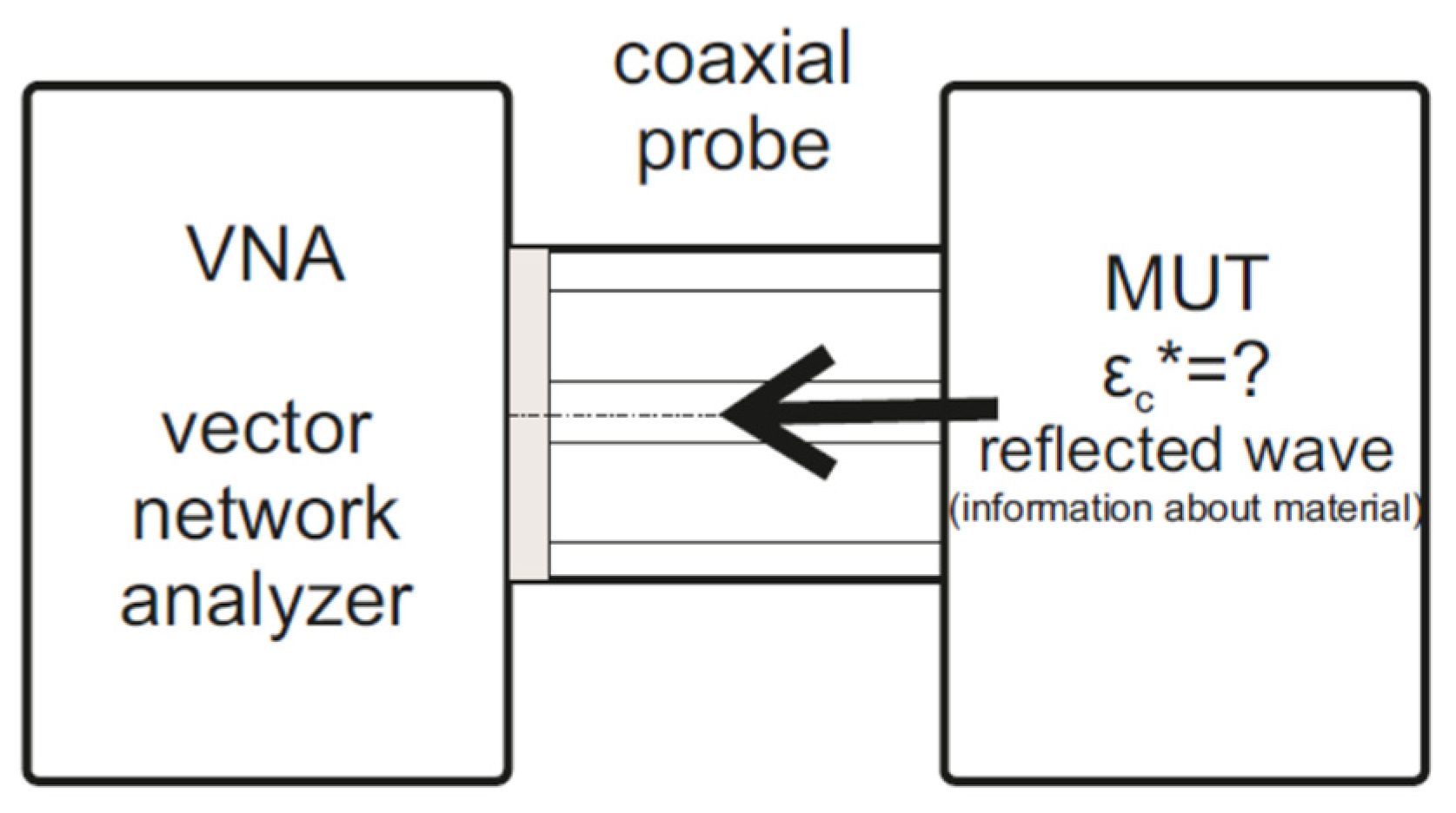
Figure 2.
Model geometry of a coaxial flange probe.
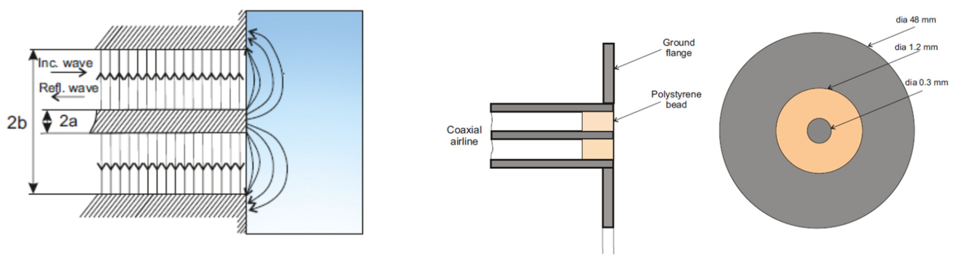
Figure 3.
Schematic diagram of a flat sample.
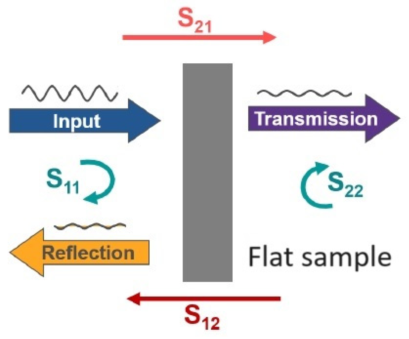
Figure 4.
Complex permittivity measurement laboratory stand.
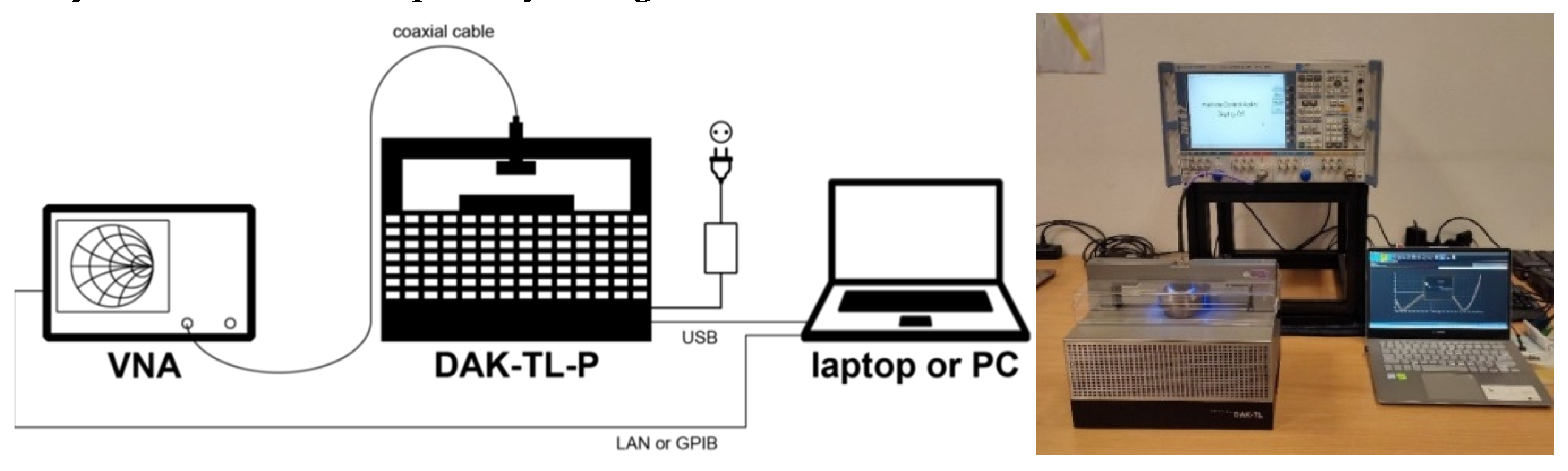
Figure 5.
Model and view of DAK 1.2 probe.
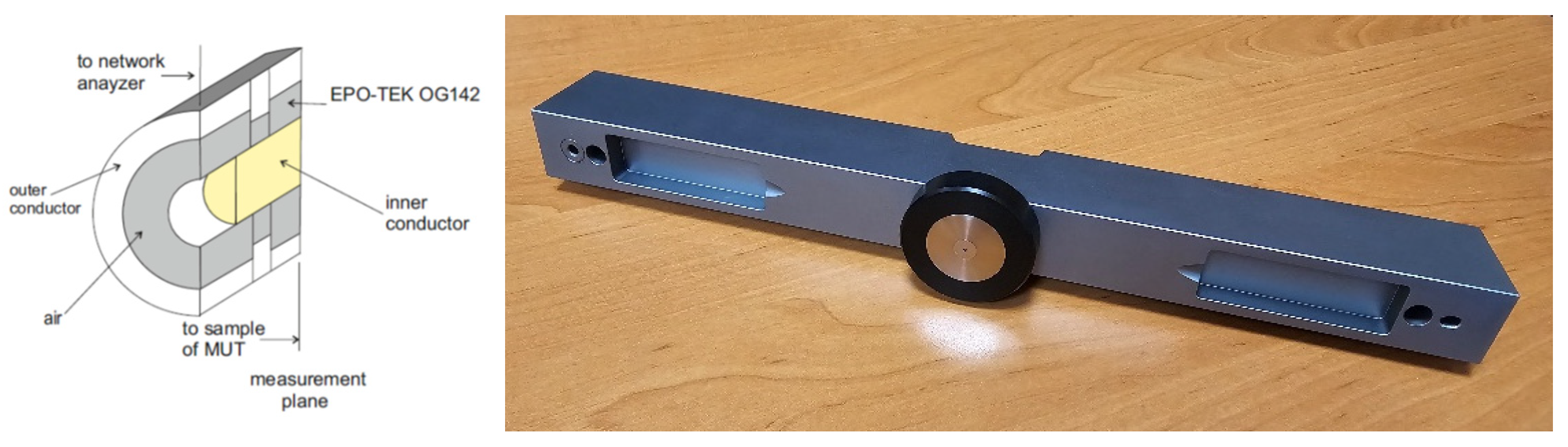
Figure 6.
The DAK-TL Calibration Kit.
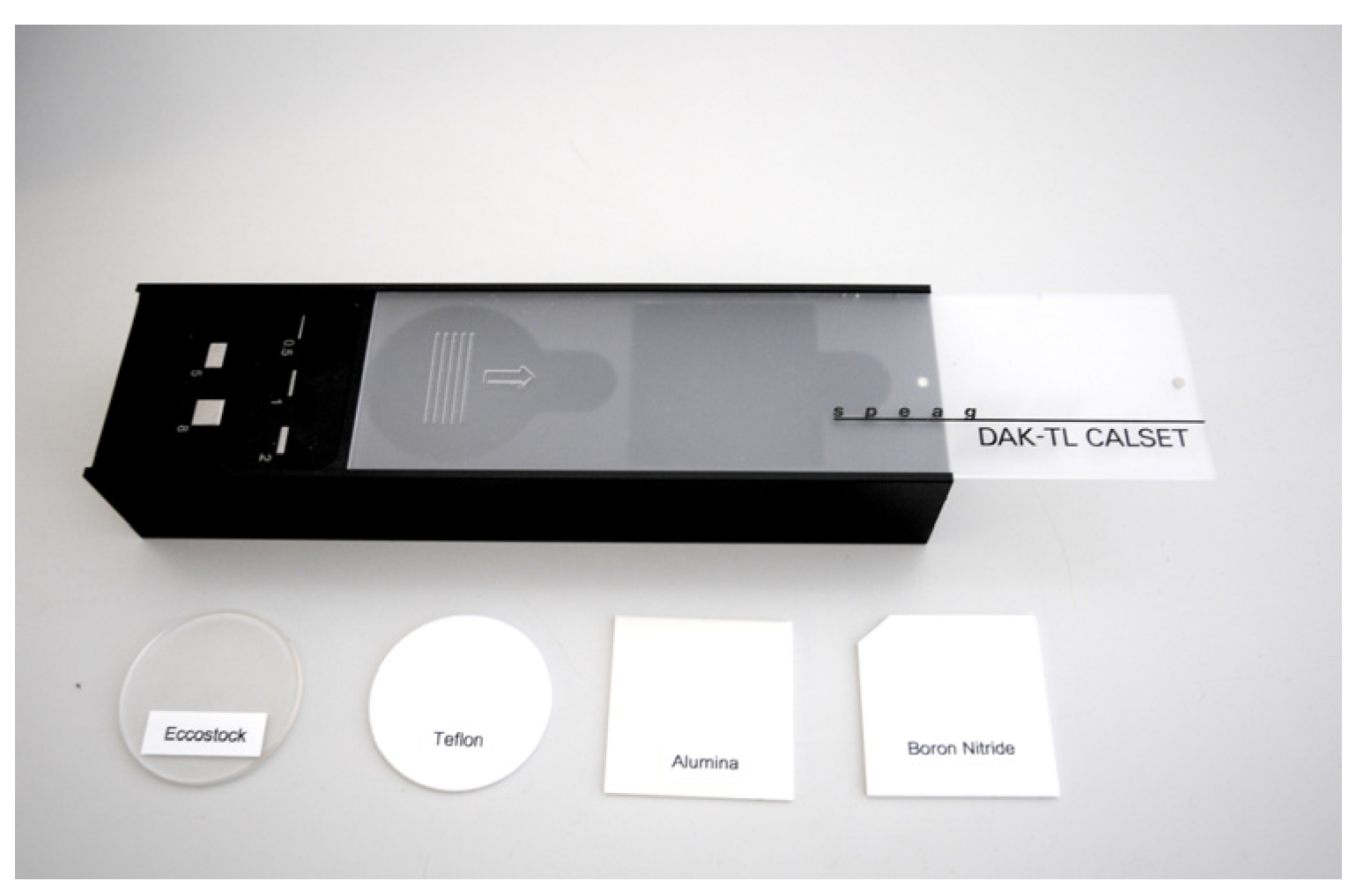
Figure 7.
Block diagram and appearance of the laboratory stand for the free space method.
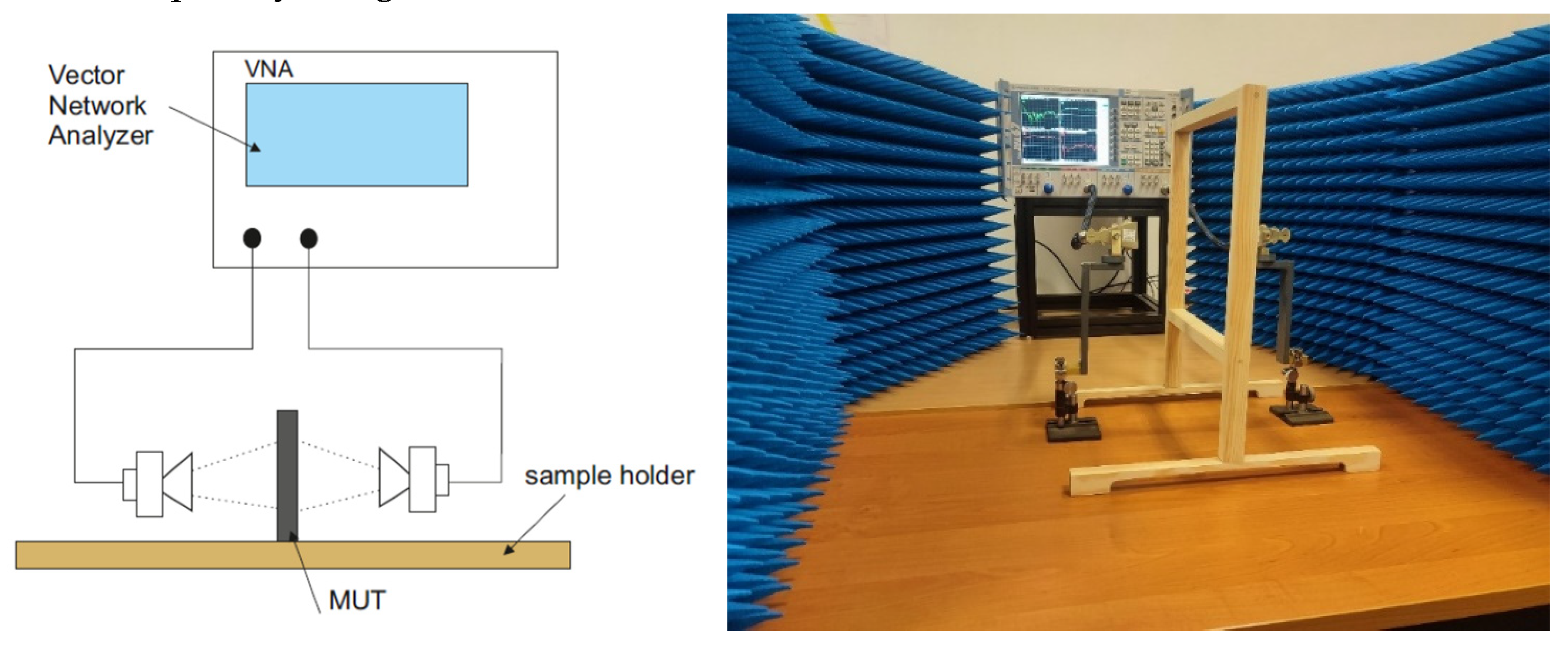
Figure 8.
Return Loss characteristics for a typically ferrite in the frequency range 10 MHz - 1 GHz.
Figure 8.
Return Loss characteristics for a typically ferrite in the frequency range 10 MHz - 1 GHz.
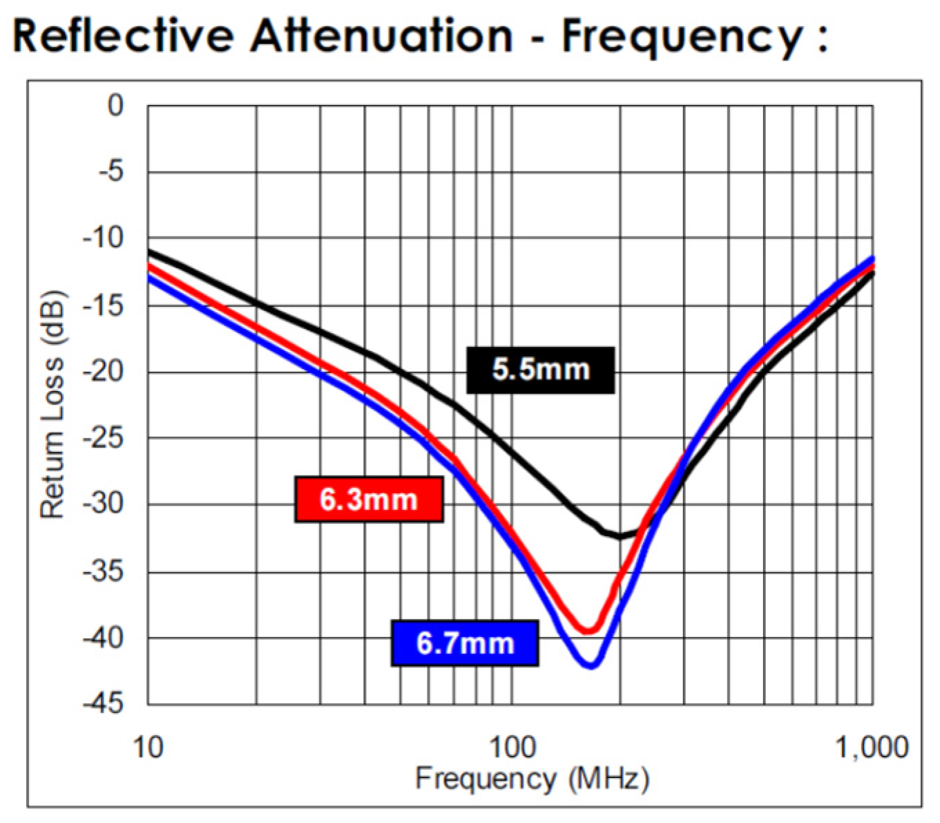
Figure 9.
The appearance of the tested sample in the form of a ferrite plate.
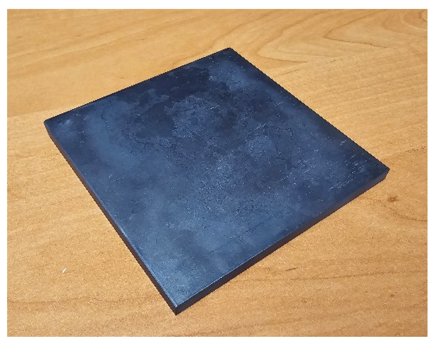
Figure 10.
Electrical permittivity values (ε', ε'') and dielectric loss values tan(δ) determined by the reflection method for a ferrite sample with dimensions of 100 x 100 x 5.5 mm.
Figure 10.
Electrical permittivity values (ε', ε'') and dielectric loss values tan(δ) determined by the reflection method for a ferrite sample with dimensions of 100 x 100 x 5.5 mm.

Figure 11.
Values of correction factors (XS11, XS21) related to measurement antennas.
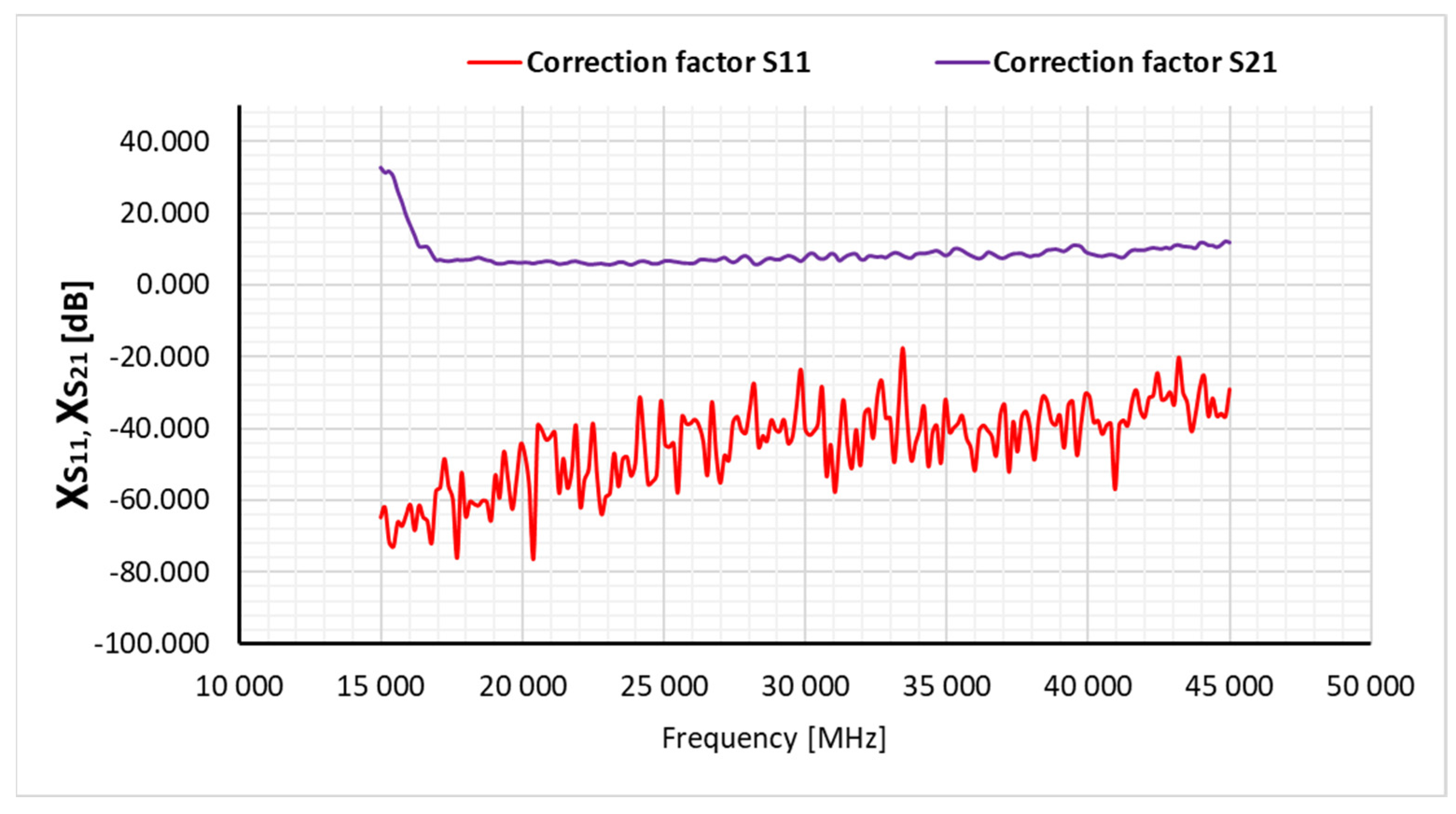
Figure 12.
Reflectance values (S11) determined by the free space method for a ferrite sample with dimensions of 100 x 100 x 5.5 mm without taking into account correction factors related to measurement antennas.
Figure 12.
Reflectance values (S11) determined by the free space method for a ferrite sample with dimensions of 100 x 100 x 5.5 mm without taking into account correction factors related to measurement antennas.
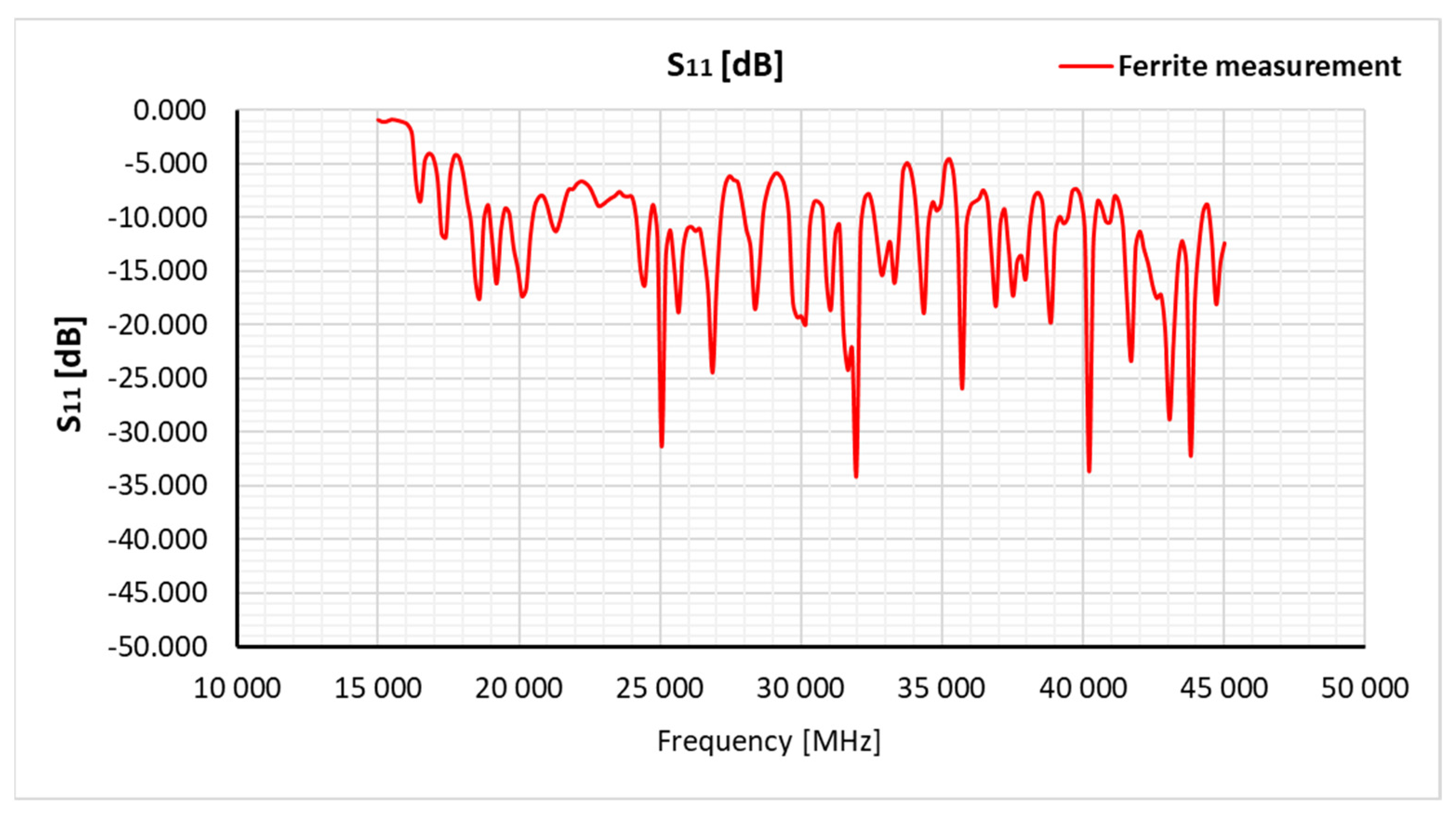
Figure 13.
Transmission coefficient values (S21) determined by the free space method for a ferrite sample with dimensions of 100 x 100 x 5.5 mm without taking into account correction factors related to measurement antennas.
Figure 13.
Transmission coefficient values (S21) determined by the free space method for a ferrite sample with dimensions of 100 x 100 x 5.5 mm without taking into account correction factors related to measurement antennas.
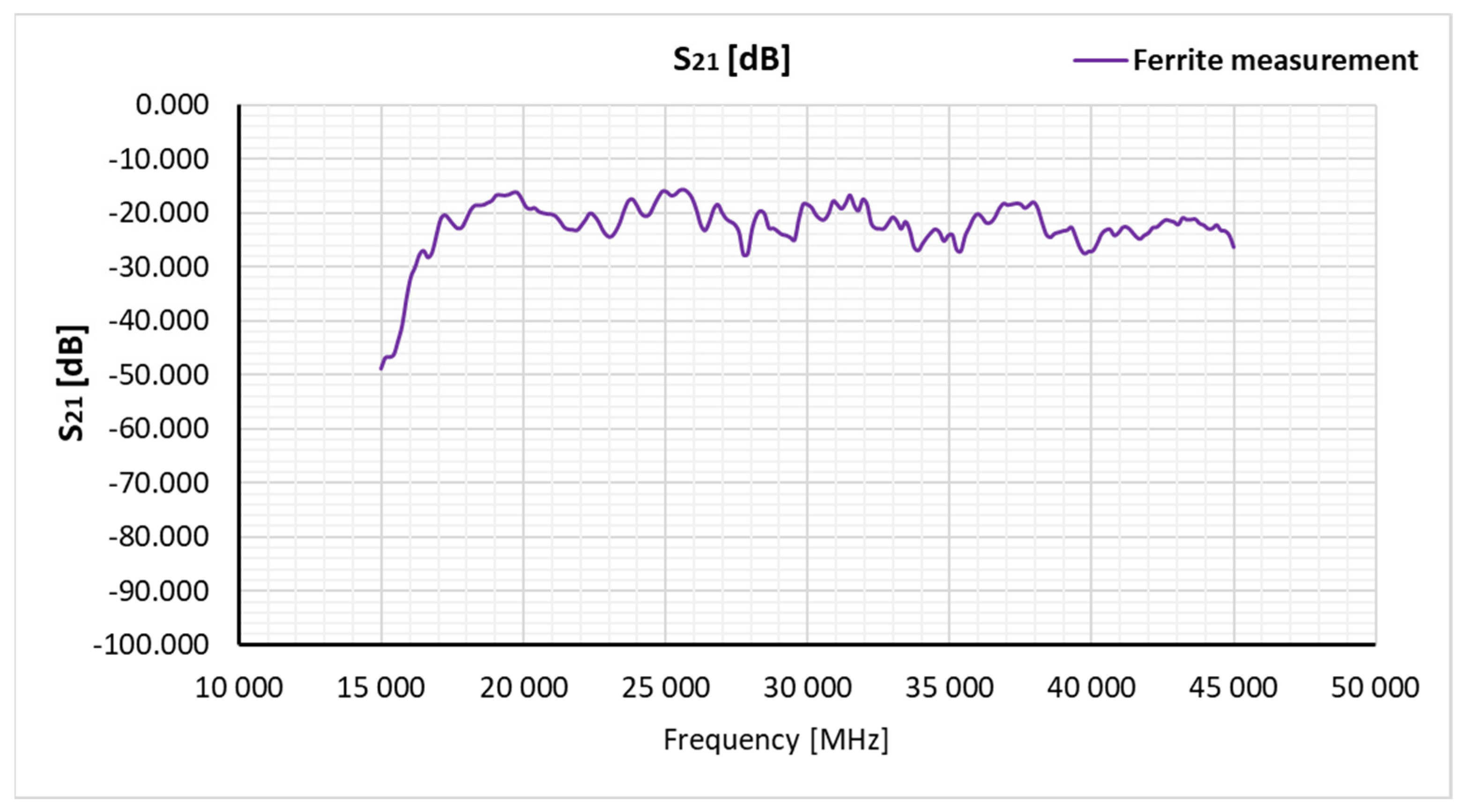
Figure 14.
Reflectance values (S11) determined by the free space method for a ferrite sample with dimensions of 100 x 100 x 5.5 mm, taking into account correction factors related to measurement antennas.
Figure 14.
Reflectance values (S11) determined by the free space method for a ferrite sample with dimensions of 100 x 100 x 5.5 mm, taking into account correction factors related to measurement antennas.
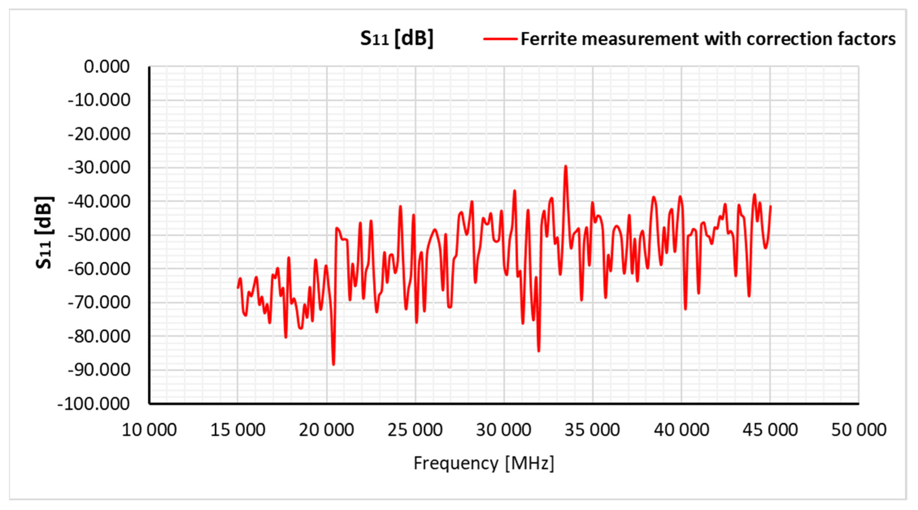
Figure 15.
Transmission coefficient values (S21) determined by the free space method for a ferrite sample with dimensions of 100 x 100 x 5.5 mm, taking into account correction factors related to measurement antennas.
Figure 15.
Transmission coefficient values (S21) determined by the free space method for a ferrite sample with dimensions of 100 x 100 x 5.5 mm, taking into account correction factors related to measurement antennas.
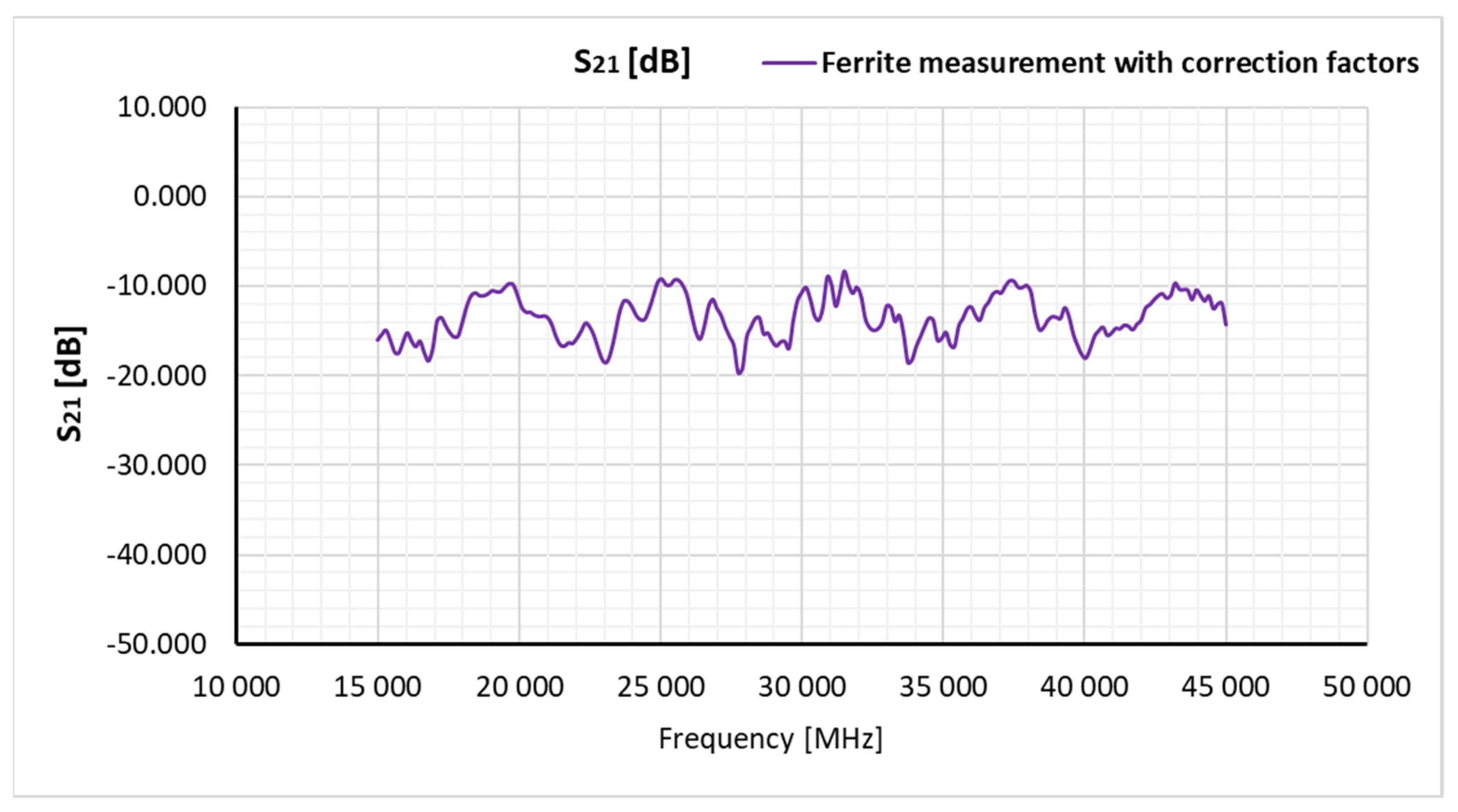
Figure 16.
Approximate values of the reflection coefficient (S11) and transmission coefficient (S21) determined by the free space method for a ferrite sample with dimensions of 100 x 100 x 5.5 mm.
Figure 16.
Approximate values of the reflection coefficient (S11) and transmission coefficient (S21) determined by the free space method for a ferrite sample with dimensions of 100 x 100 x 5.5 mm.
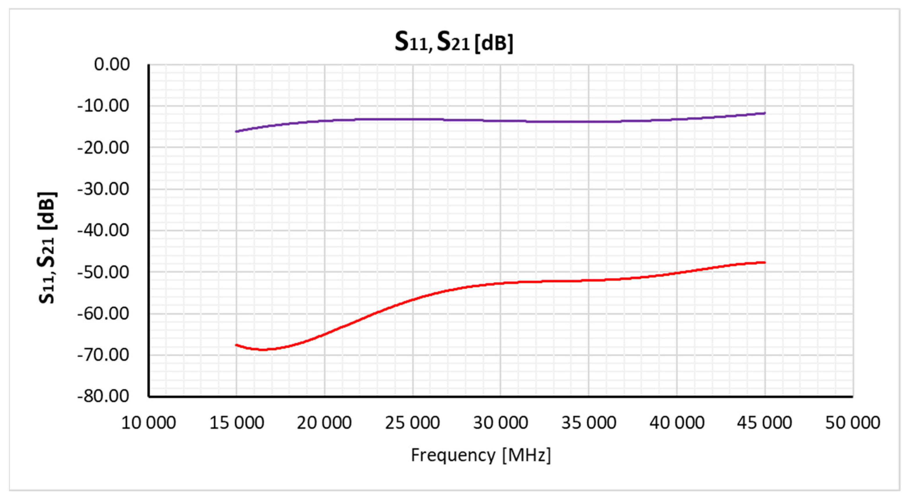
Figure 17.
Comparison of electrical permittivity values (ε') determined by the reflection method and the free space method for a ferrite sample with dimensions of 100 x 100 x 5.5 mm.
Figure 17.
Comparison of electrical permittivity values (ε') determined by the reflection method and the free space method for a ferrite sample with dimensions of 100 x 100 x 5.5 mm.
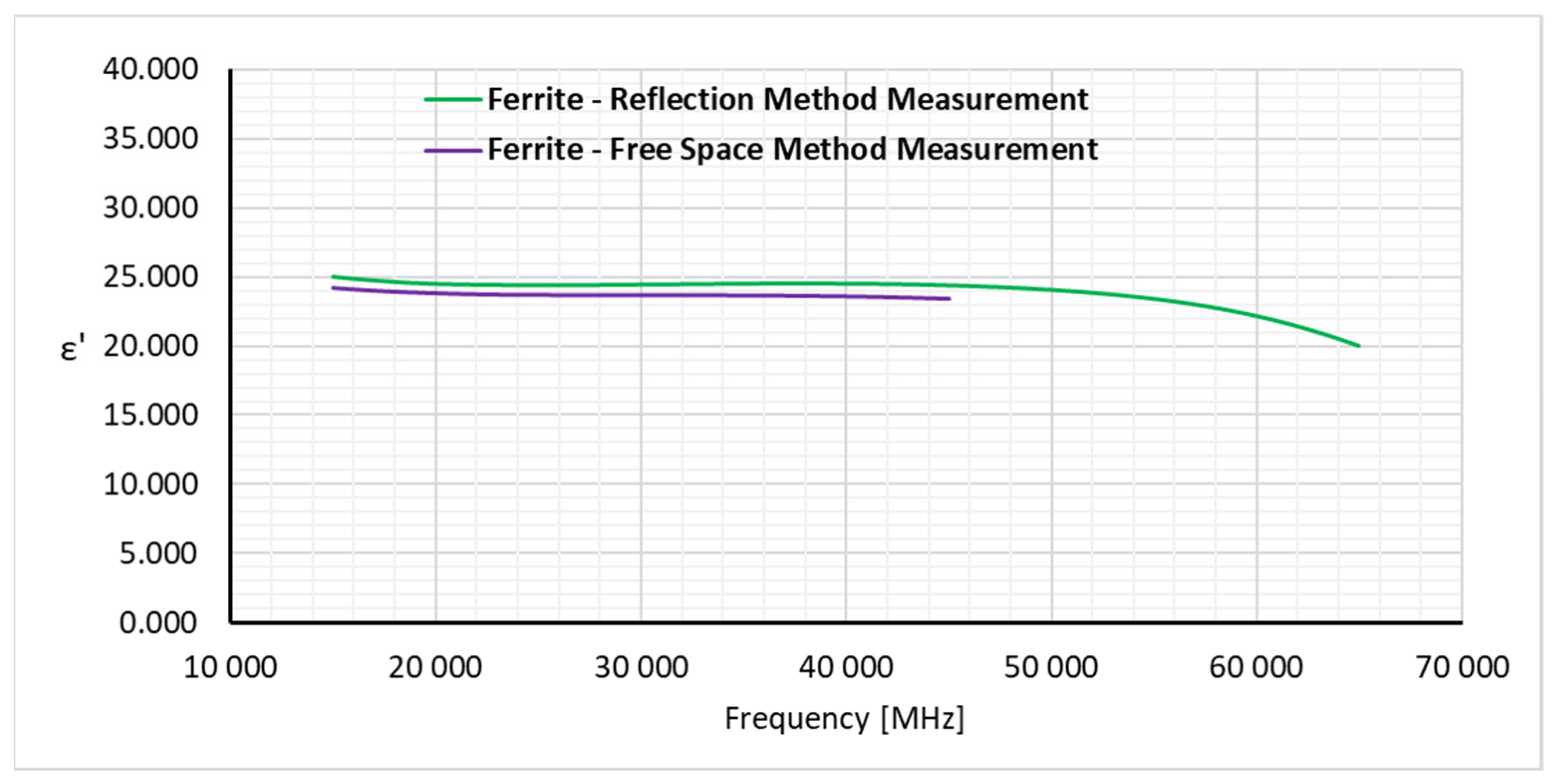
Figure 18.
Comparison of electrical permittivity values (ε'') determined by the reflection method and the free space method for a ferrite sample with dimensions of 100 x 100 x 5.5 mm.
Figure 18.
Comparison of electrical permittivity values (ε'') determined by the reflection method and the free space method for a ferrite sample with dimensions of 100 x 100 x 5.5 mm.
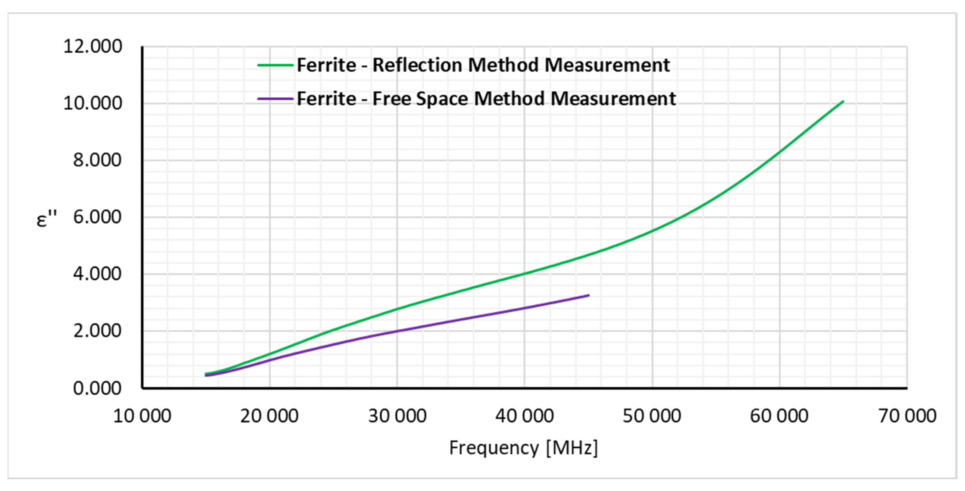
Figure 19.
Electrical permittivity values (ε', ε'') and magnetic permeability values (μ', μ'') of a ferrite plate with dimensions 100 x 100 x 5.5 mm.
Figure 19.
Electrical permittivity values (ε', ε'') and magnetic permeability values (μ', μ'') of a ferrite plate with dimensions 100 x 100 x 5.5 mm.
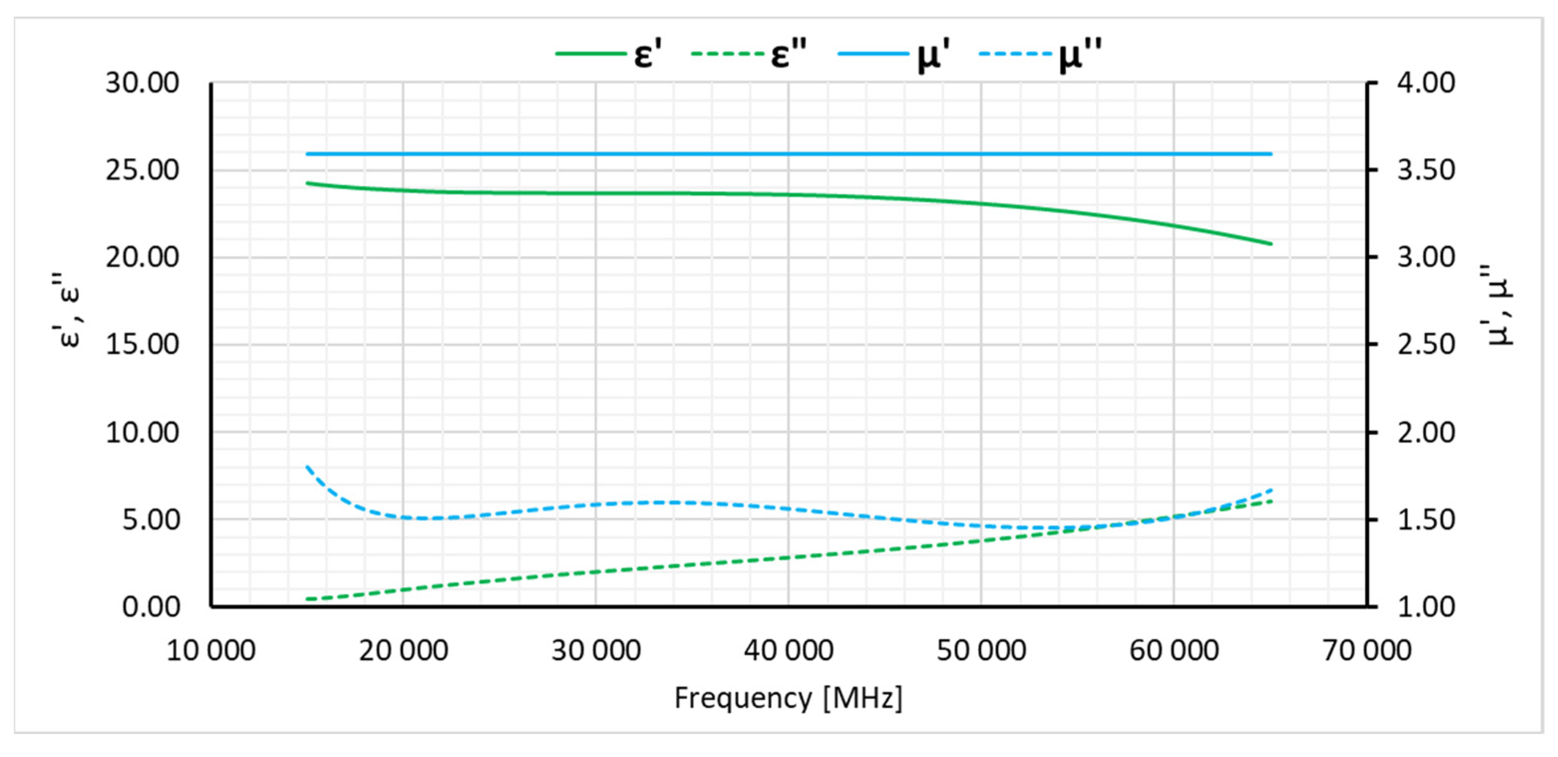

Table 1.
SAS-574 antenna specifications.
| Parameter | Range |
|---|---|
| Frequency range | 18 GHz - 45 GHz |
| Antenna factor | 40,3 do 41,1 |
| Gain | od 15 do 21,2 dBi |
| Maximum continuous power | 10 W |
| Maximum radiated field | 100 V/m |
| Impedance | 50 Ω |
| VSWR | 1,2:1 (maks. 1,5:1) |
| Connector | female 2,9 mm |
| Mounting base | ¼ - 20 thread, female |
Disclaimer/Publisher’s Note: The statements, opinions and data contained in all publications are solely those of the individual author(s) and contributor(s) and not of MDPI and/or the editor(s). MDPI and/or the editor(s) disclaim responsibility for any injury to people or property resulting from any ideas, methods, instructions or products referred to in the content. |
© 2023 by the authors. Licensee MDPI, Basel, Switzerland. This article is an open access article distributed under the terms and conditions of the Creative Commons Attribution (CC BY) license (http://creativecommons.org/licenses/by/4.0/).
Copyright: This open access article is published under a Creative Commons CC BY 4.0 license, which permit the free download, distribution, and reuse, provided that the author and preprint are cited in any reuse.


