Submitted:
01 October 2023
Posted:
04 October 2023
You are already at the latest version
Abstract
Keywords:
1. Introduction
- The choice of the membrane Young's modulus value for disc-shaped PMUT when the structural material is anisotropic (e.g., silicon);
- The equivalent lumped-element circuit components calculation according to the model chosen, i.e Foldy’s model or Mason’s model.
2. Acoustic and Mechanical Modeling of a Single PMUT Cell Coupled with a Fluid Medium
2.1. Mechanical Behavioral Equations and Resolution With Finite Difference Discretization
- 1)
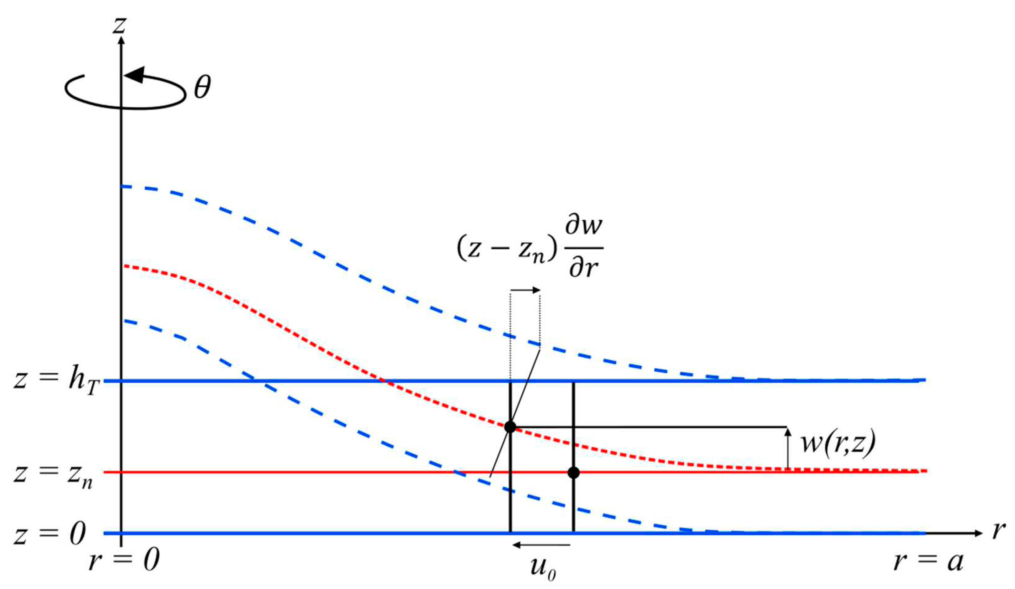
- The mechanical plate vibration is limited to the displacements (,) and (,) along the r-axis (axial displacement) and -axis (transverse displacement), respectively.
- 2)
- The through-the-thickness stresses and strains are negligible.
- 1)
- The membrane strain matrix:
- 2)
- The flexural strain matrix, known as the curvature matrix:
- (a)
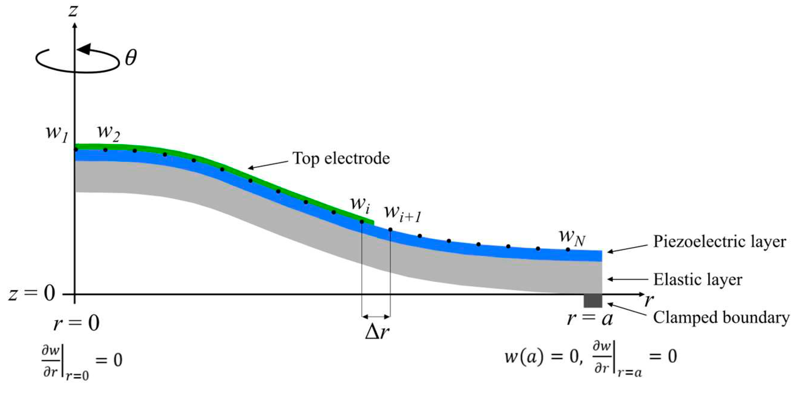
- , symmetrical boundary conditions,
- (b)
- , clamped boundary conditions.
2.2. Comparison with the Finite Element Model (FEM)
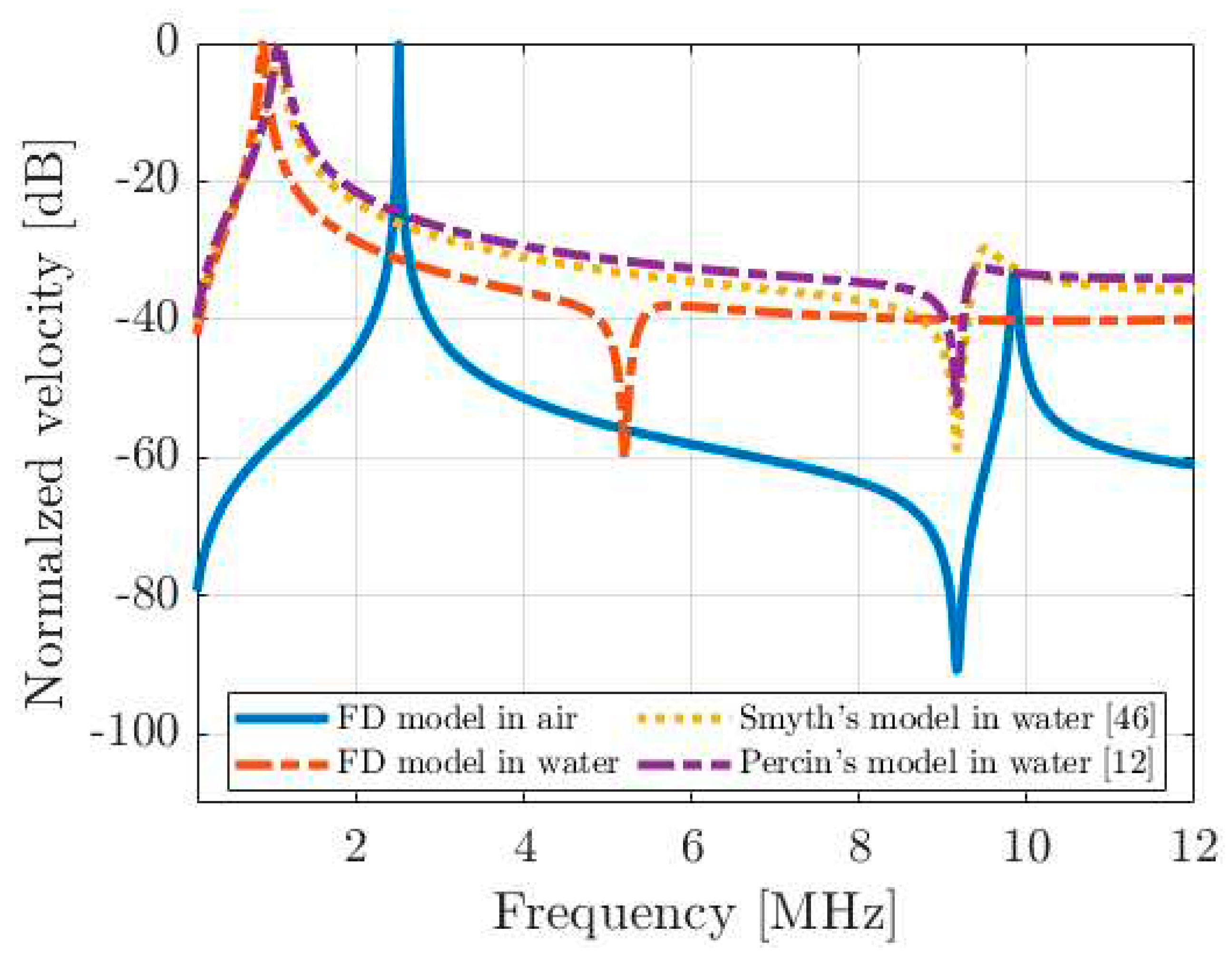
2.3. PMUT/fluid Coupling: Implementation of a Boundary Element Matrix
2.4. Comparison with Literature
3. Electroacoustic Modeling of a Single PMUT Cell Coupled with Fluid Medium
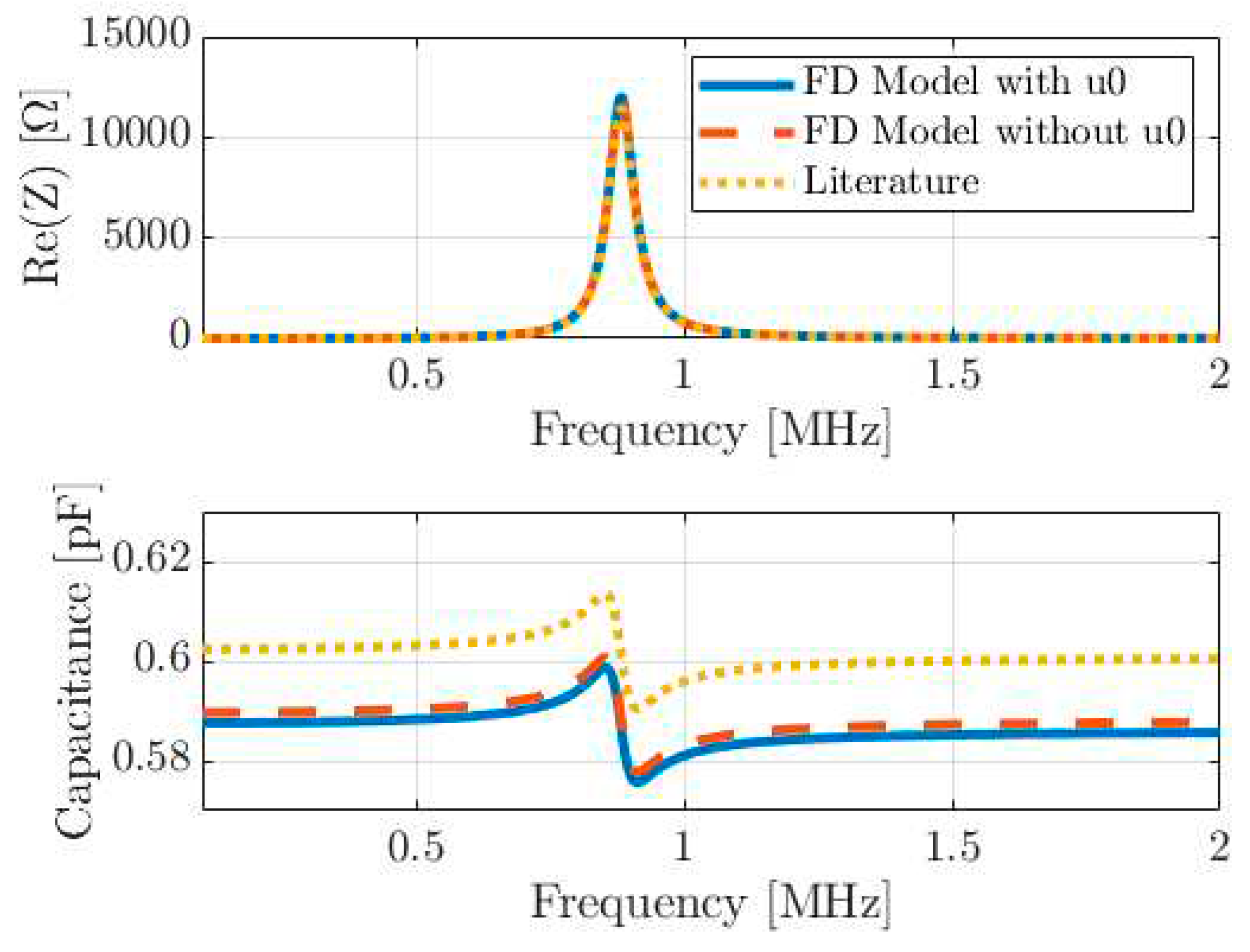
3.1. Implementation of the Piezoelectric Coupling
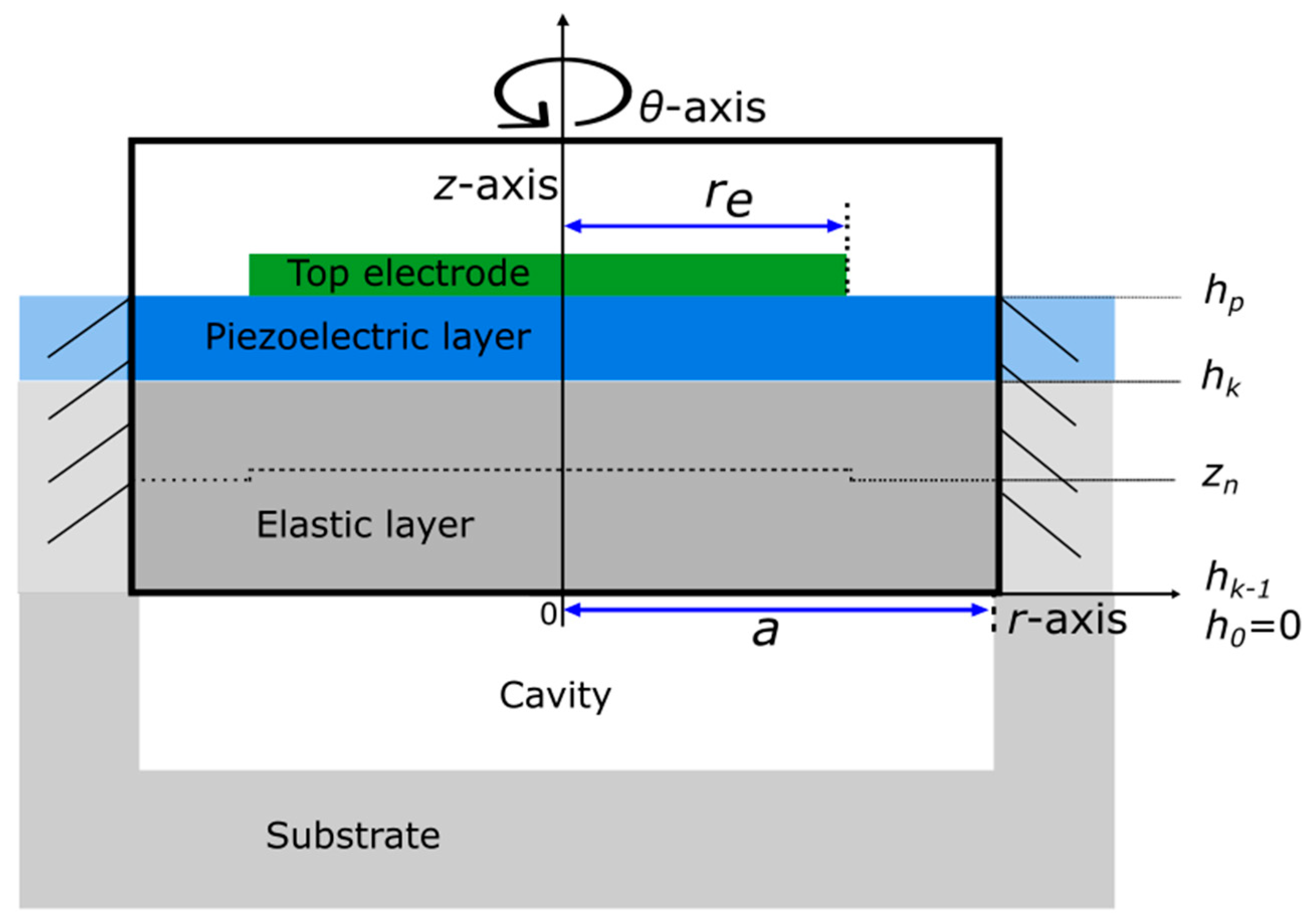
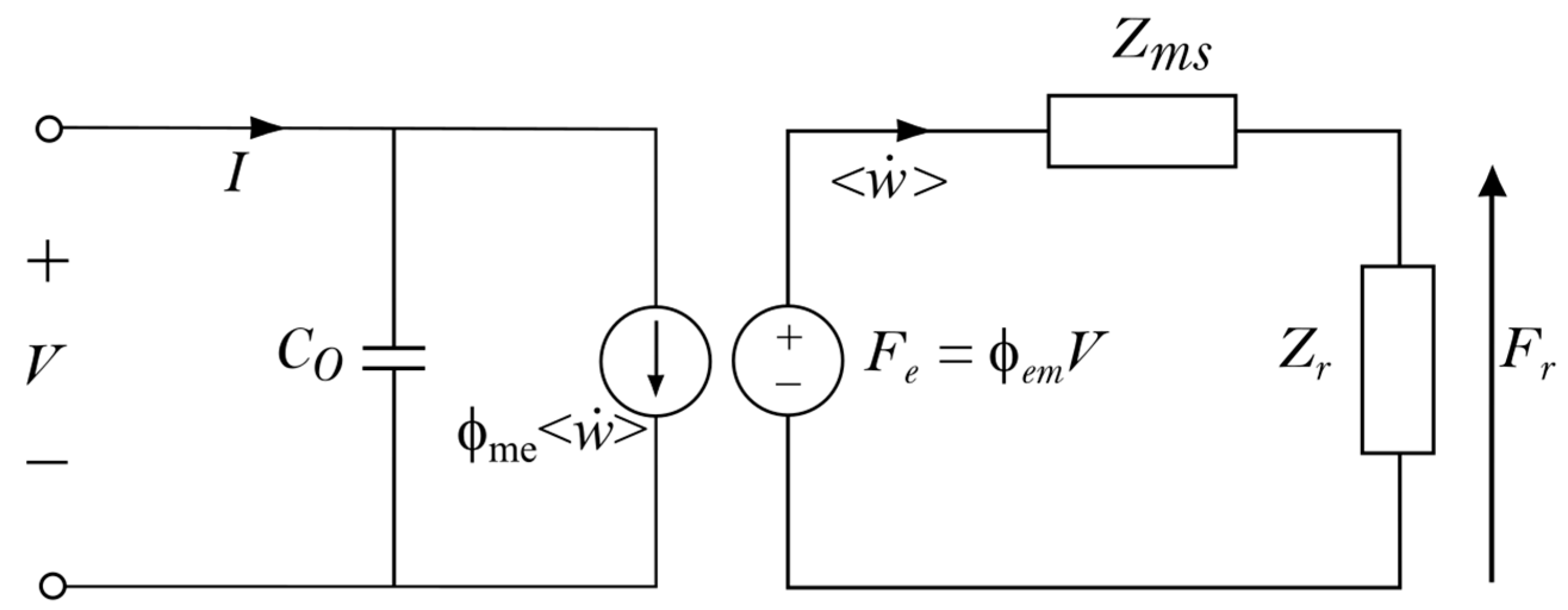
3.2. Equivalent Lumped-Element Model Implementation
- parallel electrostatic plate capacitance ,
- equivalent mechanical impedance of the plate ,
- radiation impedance ,
- electrical-to-mechanical transformation factor ,
- mechanical-to-electrical transformation factor .
4. Experimental Validation
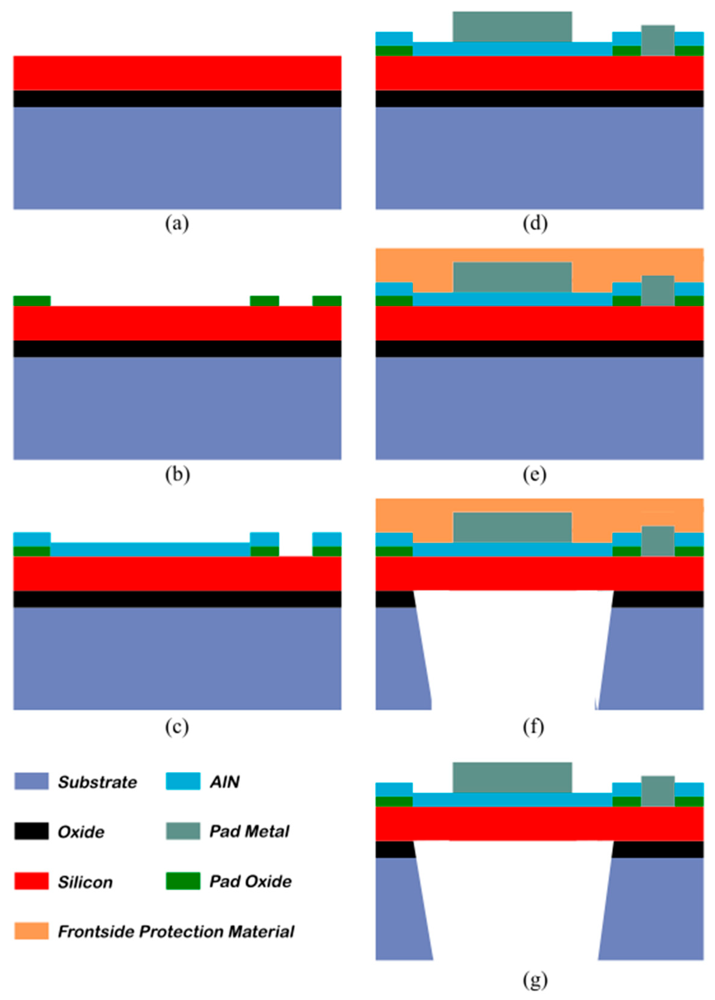
4.1. Device Description
4.2. Experimental Results and Discussion
5. Conclusions
Author Contributions
Funding
Acknowledgments
Conflicts of Interest
Appendix. Resolution of the Axial Displacement Equation
References
- P. Muralt and J. Baborowski, “Micromachined Ultrasonic Transducers and Acoustic Sensors Based on Piezoelectric Thin Films,” J. Electroceramics, vol. 12, no. 1/2, pp. 101–108, Jan. 2004. [CrossRef]
- I. Ladabaum, Xuecheng Jin, H. T. Soh, A. Atalar, and B. t. Khuri-Yakub, “Surface micromachined capacitive ultrasonic transducers,” IEEE Trans. Ultrason. Ferroelectr. Freq. Control, vol. 45, no. 3, pp. 678–690, May 1998. [CrossRef]
- K. Brenner, A. S. Ergun, K. Firouzi, M. F. Rasmussen, Q. Stedman, and B. Khuri-Yakub, “Advances in capacitive micromachined ultrasonic transducers,” Micromachines, vol. 10, no. 2, pp. 1–27, 2019. [CrossRef]
- G. Perçin, A. Atalar, F. Levent Degertekin, and B. T. Khuri-Yakub, “Micromachined two-dimensional array piezoelectrically actuated transducers,” Appl. Phys. Lett., vol. 72, no. 11, pp. 1397–1399, 1998. [CrossRef]
- G. Percin and B. T. Khuri-Yakub, “Micromachined 2-D array piezoelectrically actuated flextensional transducers,” in 1997 IEEE Ultrasonics Symposium Proceedings. An International Symposium (Cat. No.97CH36118), 1997, vol. 2, no. March, pp. 959–962. [CrossRef]
- S. Trolier-McKinstry and P. Muralt, “Thin Film Piezoelectrics for MEMS,” J. Electroceramics, vol. 12, no. 1/2, pp. 7–17, Jan. 2004. [CrossRef]
- Y. Birjis et al., “Piezoelectric Micromachined Ultrasonic Transducers (PMUTs): Performance Metrics, Advancements, and Applications,” Sensors, vol. 22, no. 23, p. 9151, Nov. 2022. [CrossRef]
- Y. He, H. Wan, X. Jiang, and C. Peng, “Piezoelectric Micromachined Ultrasound Transducer Technology: Recent Advances and Applications,” Biosensors, vol. 13, no. 1, p. 55, Dec. 2022. [CrossRef]
- Y. Qiu et al., “Piezoelectric Micromachined Ultrasound Transducer (PMUT) Arrays for Integrated Sensing, Actuation and Imaging,” Sensors, vol. 15, no. 4, pp. 8020–8041, Apr. 2015. [CrossRef]
- J. Jung, W. Lee, W. Kang, E. Shin, J. Ryu, and H. Choi, “Review of piezoelectric micromachined ultrasonic transducers and their applications,” J. Micromechanics Microengineering, vol. 27, no. 11, p. 113001, Nov. 2017. [CrossRef]
- K. Roy, J. E.-Y. Lee, and C. Lee, “Thin-film PMUTs: a review of over 40 years of research,” Microsystems Nanoeng., vol. 9, no. 1, p. 95, Jul. 2023. [CrossRef]
- G. Percin and B. T. Khuri-Yakub, “Piezoelectrically actuated flextensional micromachined ultrasound transducers. I. Theory,” IEEE Trans. Ultrason. Ferroelectr. Freq. Control, vol. 49, no. 5, pp. 573–584, May 2002. [CrossRef]
- J. Li, W. Ren, G. Fan, and C. Wang, “Design and Fabrication of Piezoelectric Micromachined Ultrasound Transducer (pMUT) with Partially-Etched ZnO Film,” Sensors, vol. 17, no. 6, p. 1381, Jun. 2017. [CrossRef]
- Q. Wang, Y. Lu, S. Mishin, Y. Oshmyansky, and D. A. Horsley, “Design, Fabrication, and Characterization of Scandium Aluminum Nitride-Based Piezoelectric Micromachined Ultrasonic Transducers,” J. Microelectromechanical Syst., vol. 26, no. 5, pp. 1132–1139, 2017. [CrossRef]
- D. S. W. Choong et al., “Silicon-On-Nothing ScAlN pMUTs,” IEEE Int. Ultrason. Symp. IUS, pp. 1–4, 2021. [CrossRef]
- P. Muralt, “Piezoelectric thin films for mems,” Integr. Ferroelectr., vol. 17, no. 1–4, pp. 297–307, Sep. 1997. [CrossRef]
- C. Cheng et al., “Improving PMUT Receive Sensitivity via DC Bias and Piezoelectric Composition,” Sensors, vol. 22, no. 15, p. 5614, Jul. 2022. [CrossRef]
- J. Baborowski, N. Ledermann, and P. Muralt, “Piezoelectric micromachined transducers (PMUT’s) based on PZT thin films,” in 2002 IEEE Ultrasonics Symposium, 2002. Proceedings., 2002, vol. 2, no. c, pp. 1051–1054. [CrossRef]
- A. S. Savoia et al., “Design, Fabrication, Characterization, and System Integration of a 1-D PMUT Array for Medical Ultrasound Imaging,” 2021. [CrossRef]
- P. Muralt, “PZT thin films for microsensors and actuators: Where do we stand?,” IEEE Trans. Ultrason. Ferroelectr. Freq. Control, vol. 47, no. 4, pp. 903–915, 2000. [CrossRef]
- S. Kim, H. G. Yeo, J. Ryu, and H. Choi, “Fabrication of surface-micromachined circular piezoelectric micromachined ultrasonic transducers with various etching holes using XeF2 and simulation of their vibrational characteristics,” Sensors Actuators A Phys., vol. 351, no. October 2022, p. 114159, Mar. 2023. [CrossRef]
- G.-L. Luo, Q. Wang, Y. Kusano, and D. Horsley, “Increased Output-Pressure PMUTs with a Sloped Profile Fabricated via Surface Micromachining,” in 2018 IEEE International Frequency Control Symposium (IFCS), May 2018, vol. 2, no. 1, pp. 1–4. [CrossRef]
- Y. Yang et al., “An Ultra-High Element Density pMUT Array with Low Crosstalk for 3-D Medical Imaging,” Sensors, vol. 13, no. 8, pp. 9624–9634, Jul. 2013. [CrossRef]
- R. J. Przybyla et al., “In-Air Rangefinding With an AlN Piezoelectric Micromachined Ultrasound Transducer,” IEEE Sens. J., vol. 11, no. 11, pp. 2690–2697, Nov. 2011. [CrossRef]
- J. Pan, C. Bai, Q. Zheng, and H. Xie, “Review of Piezoelectric Micromachined Ultrasonic Transducers for Rangefinders,” Micromachines, vol. 14, no. 2, 2023. [CrossRef]
- R. J. Przybyla, H. Y. Tang, S. E. Shelton, D. A. Horsley, and B. E. Boser, “3D ultrasonic gesture recognition,” Dig. Tech. Pap. - IEEE Int. Solid-State Circuits Conf., vol. 57, no. May, pp. 210–211, 2014. [CrossRef]
- C. H. Huang et al., “Design, modelling, and characterization of display compatible pMUT device,” in 2018 19th International Conference on Thermal, Mechanical and Multi-Physics Simulation and Experiments in Microelectronics and Microsystems (EuroSimE), Apr. 2018, pp. 1–4. [CrossRef]
- J.-H. Lee, I.-J. Cho, K. Ko, E.-S. Yoon, H.-H. Park, and T. S. Kim, “Flexible piezoelectric micromachined ultrasonic transducer (pMUT) for application in brain stimulation,” Microsyst. Technol., vol. 23, no. 7, pp. 2321–2328, Jul. 2017. [CrossRef]
- F. Pop, B. Herrera, and M. Rinaldi, “Implantable Bio-Heating System Based on Piezoelectric Micromachined Ultrasonic Transducers,” in 2020 IEEE 33rd International Conference on Micro Electro Mechanical Systems (MEMS), Jan. 2020, vol. 2020-Janua, pp. 842–844. [CrossRef]
- A. Hajati et al., “Three-dimensional micro electromechanical system piezoelectric ultrasound transducer,” Appl. Phys. Lett., vol. 101, no. 25, p. 253101, Dec. 2012. [CrossRef]
- S. Akhbari, F. Sammoura, and Liwei Lin, “An equivalent circuit model for curved piezoelectric micromachined ultrasonic transducers with spherical-shape diaphragms,” in 2014 IEEE International Ultrasonics Symposium, Sep. 2014, pp. 301–304. [CrossRef]
- S. Akhbari, F. Sammoura, and L. Lin, “Equivalent Circuit Models for Large Arrays of Curved and Flat Piezoelectric Micromachined Ultrasonic Transducers,” IEEE Trans. Ultrason. Ferroelectr. Freq. Control, vol. 63, no. 3, pp. 432–447, 2016. [CrossRef]
- T. Xu et al., “Equivalent Circuit Model for a Large Array of Coupled Piezoelectric Micromachined Ultrasonic Transducers with High Emission Performance,” IEEE Trans. Ultrason. Ferroelectr. Freq. Control, vol. 68, no. 3, pp. 718–733, 2021. [CrossRef]
- C. Liu et al., “Theoretical Modeling of Piezoelectric Micromachined Ultrasonic Transducers With Honeycomb Structure,” J. Microelectromechanical Syst., pp. 1–10, 2022. [CrossRef]
- F. Sammoura, K. Smyth, and S.-G. Kim, “Working equations of a circular multimorph piezoelectric micromachined ultrasonic transducer,” in IECON 2012 - 38th Annual Conference on IEEE Industrial Electronics Society, Oct. 2012, pp. 3991–3996. [CrossRef]
- F. Sammoura, S. Akhari, N. Aqab, M. Mahmoud, and L. Lin, “Multiple electrode piezoelectric micromachined ultrasonic transducers,” IEEE Int. Ultrason. Symp. IUS, pp. 305–308, 2014. [CrossRef]
- T. Merrien, “Transducteurs ultrasonores capacitifs micro-usinés pour l’imagerie 3D : adressage ligne-colonne du réseau matriciel,” Tours, 2022.
- M. Maadi and R. J. Zemp, “Self and Mutual Radiation Impedances for Modeling of Multi-Frequency CMUT Arrays,” IEEE Trans. Ultrason. Ferroelectr. Freq. Control, vol. 63, no. 9, pp. 1441–1454, Sep. 2016. [CrossRef]
- R. L. Pritchard, “Mutual Acoustic Impedance between Radiators in an Infinite Rigid Plane,” J. Acoust. Soc. Am., vol. 32, no. 6, pp. 730–737, Jun. 1960. [CrossRef]
- D. T. Porter, “Self- and Mutual-Radiation Impedance and Beam Patterns for Flexural Disks in a Rigid Plane,” J. Acoust. Soc. Am., vol. 36, no. 6, pp. 1154–1161, Jun. 1964. [CrossRef]
- C. Meynier, F. Teston, and D. Certon, “A multiscale model for array of capacitive micromachined ultrasonic transducers,” J. Acoust. Soc. Am., vol. 128, no. 5, pp. 2549–2561, 2010. [CrossRef]
- H. K. Oguz, A. Atalar, and H. Koymen, “Equivalent circuit-based analysis of CMUT cell dynamics in arrays,” IEEE Trans. Ultrason. Ferroelectr. Freq. Control, vol. 60, no. 5, pp. 1016–1024, May 2013. [CrossRef]
- A. Boulmé and D. Certon, “Design of broadband linear micromachined ultrasonic transducer arrays by means of boundary element method coupled with normal mode theory,” IEEE Trans. Ultrason. Ferroelectr. Freq. Control, vol. 62, no. 9, pp. 1704–1716, 2015. [CrossRef]
- B. Shieh, K. G. Sabra, and F. Levent Degertekin, “A Hybrid Boundary Element Model for Simulation and Optimization of Large Piezoelectric Micromachined Ultrasonic Transducer Arrays,” IEEE Trans. Ultrason. Ferroelectr. Freq. Control, vol. 65, no. 1, pp. 50–59, 2018. [CrossRef]
- Q. Wang and D. A. Horsley, “Using a mutual acoustic impedance model to improve the time domain response of PMUT arrays,” IEEE Int. Ultrason. Symp. IUS, pp. 9–12, 2017. [CrossRef]
- K. Smyth and S. Kim, “Experiment and simulation validated analytical equivalent circuit model for piezoelectric micromachined ultrasonic transducers,” IEEE Trans. Ultrason. Ferroelectr. Freq. Control, vol. 62, no. 4, pp. 744–765, Apr. 2015. [CrossRef]
- D.-G. Zhang and Y.-H. Zhou, “A theoretical analysis of FGM thin plates based on physical neutral surface,” Comput. Mater. Sci., vol. 44, no. 2, pp. 716–720, Dec. 2008. [CrossRef]
- S. Ho, “Modeling of a Disk-Type Piezoelectric Transformer,” IEEE Trans. Ultrason. Ferroelectr. Freq. Control, vol. 54, no. 10, pp. 2110–2119, Oct. 2007. [CrossRef]
- F. Sammoura and S. G. Kim, “Modeling of the neutral axes of a circular piezoelectric micromachined transducer in transmit and receive mode,” Tech. Dig. - Solid-State Sensors, Actuators, Microsystems Work., vol. 1, pp. 485–488, 2012. [CrossRef]
- M. A. Eltaher, A. E. Alshorbagy, and F. F. Mahmoud, “Determination of neutral axis position and its effect on natural frequencies of functionally graded macro/nanobeams,” Compos. Struct., vol. 99, pp. 193–201, 2013. [CrossRef]
- D. G. Zhang, “Thermal post-buckling and nonlinear vibration analysis of FGM beams based on physical neutral surface and high order shear deformation theory,” Meccanica, vol. 49, no. 2, pp. 283–293, 2014. [CrossRef]
- S. Flight, “NASA Reference Publication 1351 Basic Mechanics of Laminated Composite Plates,” no. October 1994, 2020, [Online]. Available: https://ntrs.nasa.gov/api/citations/19950009349/downloads/19950009349.pdf.
- D. Certon, F. Teston, and F. Patat, “A finite difference model For cMUT devices,” IEEE Trans. Ultrason. Ferroelectr. Freq. Control, vol. 52, no. 12, pp. 2199–2210, Dec. 2005. [CrossRef]
- X. Yang, A. El Baroudi, and J. Y. Le Pommellec, “Free Vibration Investigation of Submerged Thin Circular Plate,” Int. J. Appl. Mech., vol. 12, no. 3, Apr. 2020. [CrossRef]
- D. h. c. S. Littmarck and M. F. Saeidi, “COMSOL Multiphysycs,” 1986. https://www.comsol.fr/.
- Michel Geradin and Daniel Rixen, Mechanical Vibrations - Theory and Application to Structural Dynamics, no. 1. 2015.
- S. Timoshenko et al., Theories of Plates and Shells, vol. 16. Berlin, Heidelberg: Springer Berlin Heidelberg, 2004.
- J. N. Reddy, Theory and Analysis of Elastic Plates and Shells, vol. 148. CRC Press, 2006.
- C. Chare, P. Gijsenbergh, Y. Jeong, P. Heremans, D. Cheyns, and J. Genoe, “Electromechanical Equivalent Circuit Model for Axisymmetric PMUTs With Elastic Boundary Conditions,” J. Microelectromechanical Syst., pp. 1–16, 2022. [CrossRef]
- F. Sammoura and S. G. Kim, “Theoretical modeling and equivalent electric circuit of a bimorph piezoelectric micromachined ultrasonic transducer,” IEEE Trans. Ultrason. Ferroelectr. Freq. Control, vol. 59, no. 5, pp. 990–998, 2012. [CrossRef]
- T. Xu et al., “An Analytical Equivalent Circuit Model for Optimization Design of a Broadband Piezoelectric Micromachined Ultrasonic Transducer with an Annular Diaphragm,” IEEE Trans. Ultrason. Ferroelectr. Freq. Control, vol. 66, no. 11, pp. 1760–1776, 2019. [CrossRef]
- A. Ben Amar, H. Cao, and A. B. Kouki, “Modeling and process design optimization of a piezoelectric micromachined ultrasonic transducers (PMUT) using lumped elements parameters,” Microsyst. Technol., vol. 23, no. 10, pp. 4659–4669, Oct. 2017. [CrossRef]
- K. Smyth, S. Bathurst, F. Sammoura, and Sang-Gook Kim, “Analytic solution for N-electrode actuated piezoelectric disk with application to piezoelectric micromachined ultrasonic transducers,” IEEE Trans. Ultrason. Ferroelectr. Freq. Control, vol. 60, no. 8, pp. 1756–1767, Aug. 2013. [CrossRef]
- S. A. N. Prasad et al., “Analytical electroacoustic model of a piezoelectric composite circular plate,” AIAA J., vol. 44, no. 10, pp. 2311–2318, 2006. [CrossRef]
- M. Deshpande and L. Saggere, “An analytical model and working equations for static deflections of a circular multi-layered diaphragm-type piezoelectric actuator,” Sensors Actuators A Phys., vol. 136, no. 2, pp. 673–689, May 2007. [CrossRef]
- F. Sammoura, K. Smyth, and S.-G. Kim, “Optimizing the electrode size of circular bimorph plates with different boundary conditions for maximum deflection of piezoelectric micromachined ultrasonic transducers,” Ultrasonics, vol. 53, no. 2, pp. 328–334, Feb. 2013. [CrossRef]
- M. A. Hopcroft, W. D. Nix, and T. W. Kenny, “What is the Young’s Modulus of Silicon?,” J. Microelectromechanical Syst., vol. 19, no. 2, pp. 229–238, Apr. 2010. [CrossRef]
- M. F. la Cour, “Micromachined Integrated Transducers for Ultrasound Imaging,” Technical University of Denmark, 2014.
- A. Robichaud, D. Deslandes, P.-V. Cicek, and F. Nabki, “A Novel Topology for Process Variation-Tolerant Piezoelectric Micromachined Ultrasonic Transducers,” J. Microelectromechanical Syst., vol. 27, no. 6, pp. 1204–1212, Dec. 2018. [CrossRef]
- A. F. Seybert, B. Soenarko, F. J. Rizzo, and D. J. Shippy, “A special integral equation formulation for acoustic radiation and scattering for axisymmetric bodies and boundary conditions,” J. Acoust. Soc. Am., vol. 80, no. 4, pp. 1241–1247, Oct. 1986. [CrossRef]
- C.H. Sherman and J. L. Butler, Transducers and Arrays for Underwater Sound, vol. 124, no. 3. New York, NY: Springer New York, 2007.
- S. Pala and L. Lin, “An Improved Lumped Element Model for Circular-Shape pMUTs,” IEEE Open J. Ultrason. Ferroelectr. Freq. Control, vol. 2, no. May, pp. 83–95, 2022. [CrossRef]
- C. H. Nguyen, U. Hanke, and E. Halvorsen, “Constitutive Equations of Piezoelectric Layered Beams With Interdigitated Electrodes,” IEEE Trans. Ultrason. Ferroelectr. Freq. Control, vol. 65, no. 9, pp. 1680–1694, Sep. 2018. [CrossRef]
- T. Merrien, A. Boulme, and D. Certon, “Lumped-Parameter Equivalent Circuit Modeling of CMUT Array Elements,” IEEE Open J. Ultrason. Ferroelectr. Freq. Control, vol. 2, pp. 1–16, 2022. [CrossRef]
- L. L. Foldy, “Theory of Passive Linear Electroacoustic Transducers with Fixed Velocity Distributions,” J. Acoust. Soc. Am., vol. 21, no. 1, pp. 57–57, Jan. 1949. [CrossRef]
- L. L. Foldy and H. Primakoff, “A General Theory of Passive Linear Electroacoustic Transducers and the Electroacoustic Reciprocity Theorem. I,” J. Acoust. Soc. Am., vol. 17, no. 2, pp. 109–120, Oct. 1945. [CrossRef]
- A. Cowen, G. Hames, K. Glukh, and B. Hardy, “PiezoMUMPs Design Handbook a MUMPs ® process,” MEMSCAP Inc, vol. 1, 2014.
- D. Certon, G. Ferin, O. Bou Matar, J. Guyonvarch, J. P. Remenieras, and F. Patat, “Influence of acousto-optic interactions on the determination of the diffracted field by an array obtained from displacement measurements,” Ultrasonics, vol. 42, no. 1–9, pp. 465–471, 2004. [CrossRef]
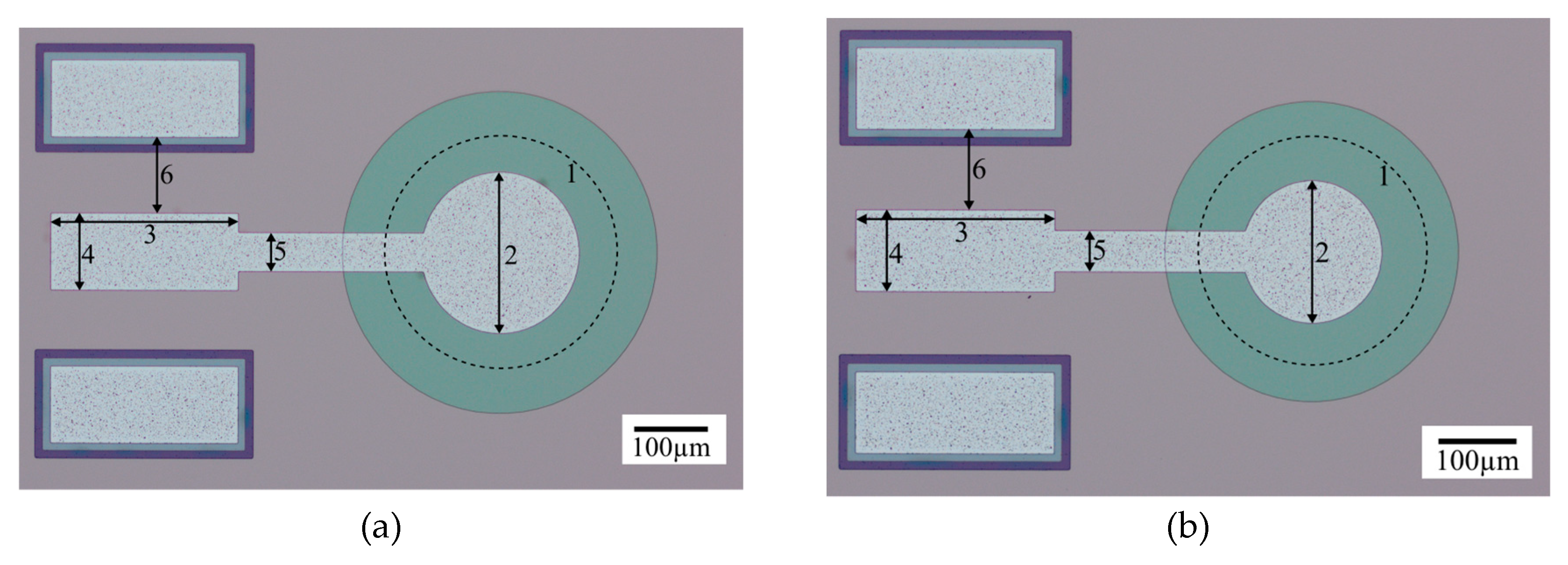
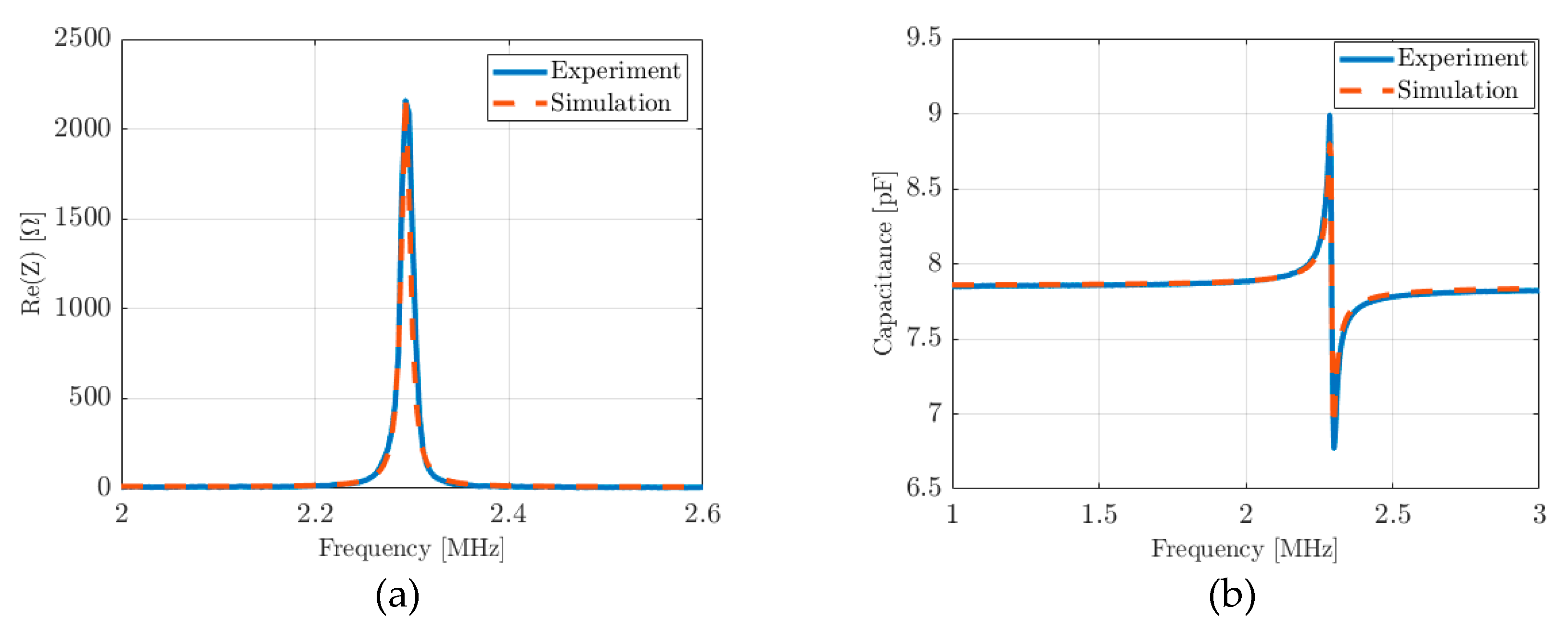
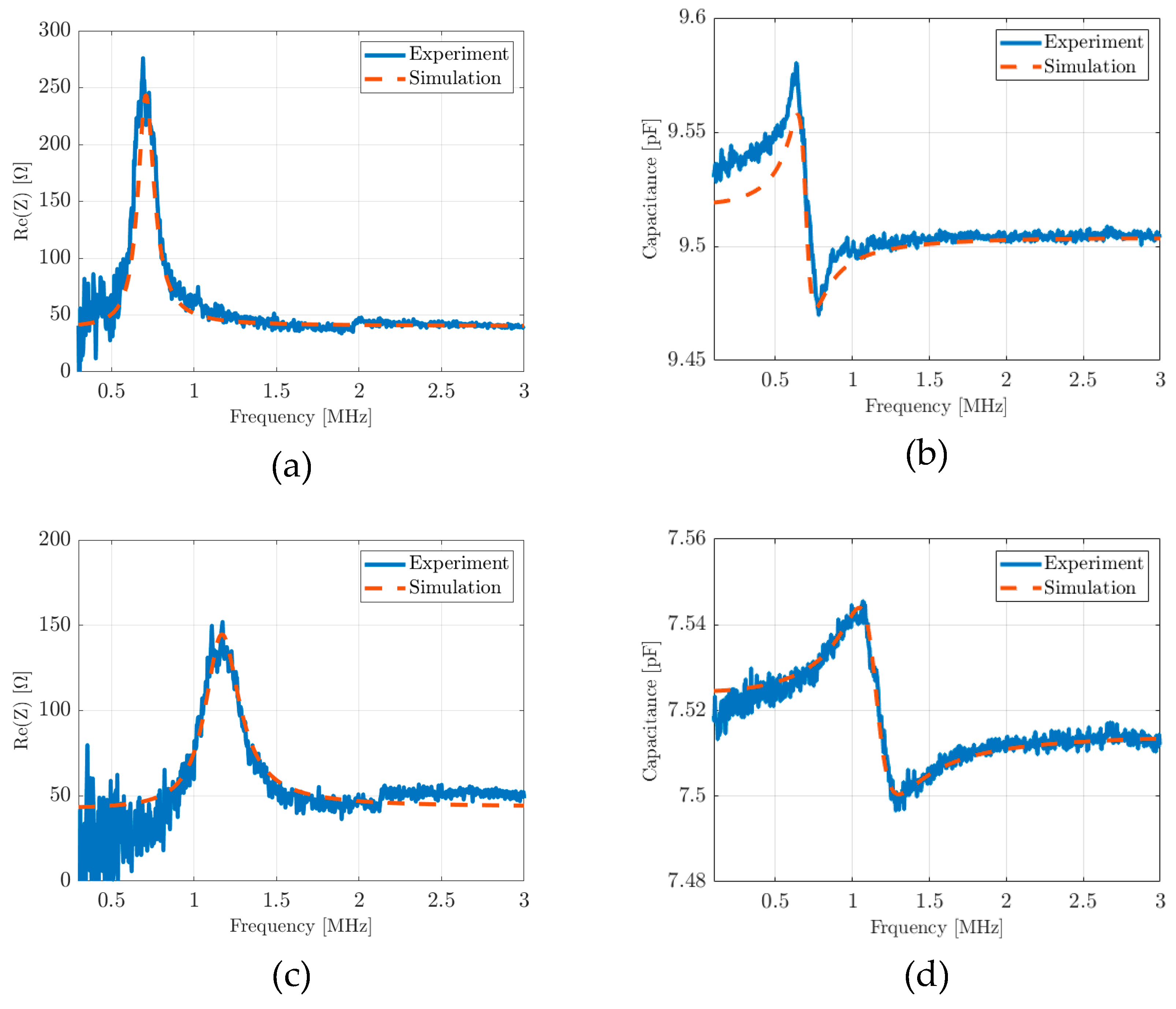
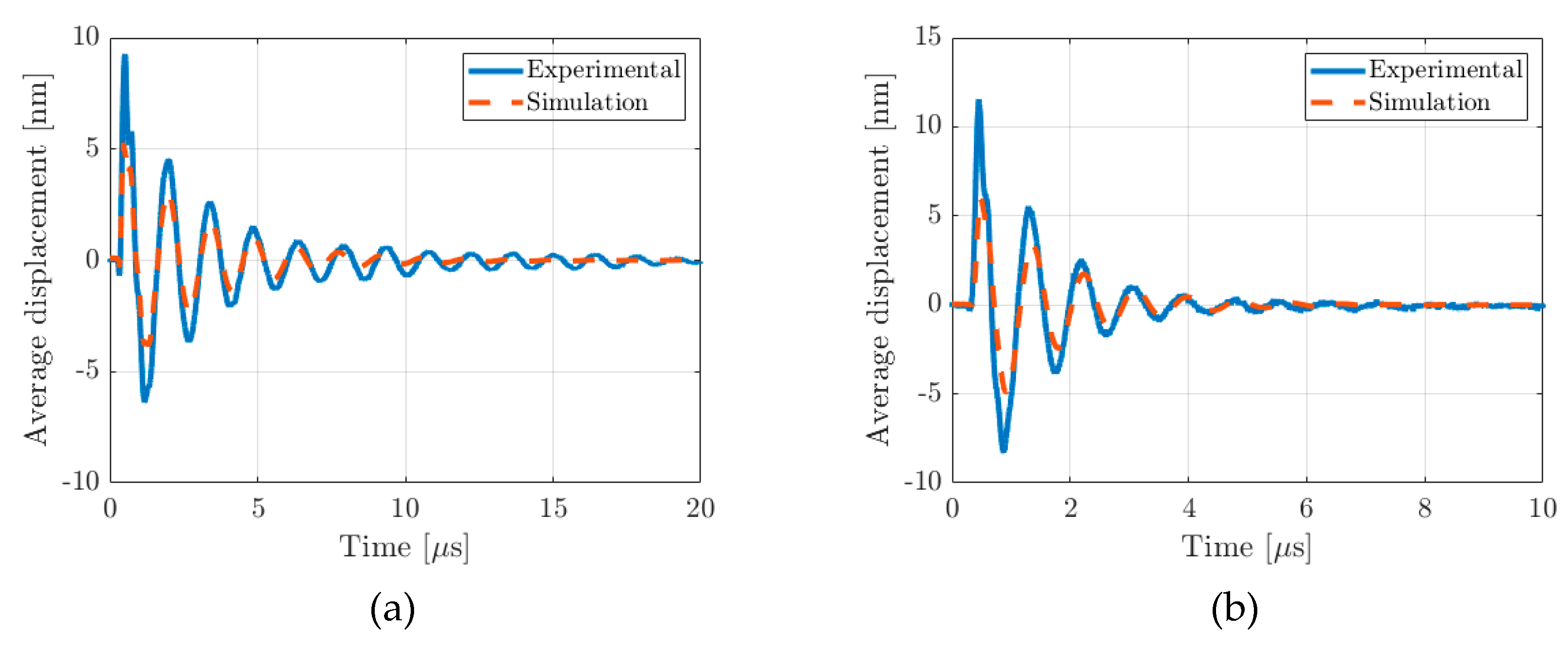
| Layer | Si | AlN | Al |
| Thickness [µm] | 1 | 0.5 | 0.2 |
| Radius [µm] | 50 | 50 | 0-50 |
| Young’s Modulus [GPa] | 143 | 348 | 69 |
| Poisson’s ratio | 0.28 | 0.24 | 0.35 |
| Density [kg/m3] | 2330 | 3600 | 2700 |
| d31 [pC/N] | - | -2.05 | - |
| - | 10 | - |
| Layer | Si | AlN | Cr | Al | ||||
| Device | 1 | 2 | 1 | 2 | 1 | 2 | 1 | 2 |
| Diameter [µm] | 340 | 275 | 340 | 275 | 211 | 173 | 211 | 173 |
| Thickness [µm] | 10 | 0.5 | 0.2 | 1 | ||||
| Young’s modulus [GPa] | 143 | 348 | 279 | 69 | ||||
| Poisson’s ratio | 0.28 | 0.24 | 0.21 | 0.35 | ||||
| Density [kg/m3] | 2330 | 3600 | 7190 | 2700 | ||||
| d31 [pC/N] | - | -2.05 | - | - | ||||
| - | 10 | - | - | |||||
Disclaimer/Publisher’s Note: The statements, opinions and data contained in all publications are solely those of the individual author(s) and contributor(s) and not of MDPI and/or the editor(s). MDPI and/or the editor(s) disclaim responsibility for any injury to people or property resulting from any ideas, methods, instructions or products referred to in the content. |
© 2023 by the authors. Licensee MDPI, Basel, Switzerland. This article is an open access article distributed under the terms and conditions of the Creative Commons Attribution (CC BY) license (http://creativecommons.org/licenses/by/4.0/).


