1. Introduction
A flotation plant comprises multiple flotation stages, such as roughing, cleaning, and scavenging, to attain a targeted metallurgical performance. These stages consist of flotation units or banks, with the latter typically being composed of serial arrangements of mechanical cells, i.e., the tail of a cell is the feed to the subsequent cell down the bank. Mechanical cells can be of different types; for example, forced-air tank cells, self-aspirated cells, or reactor-separator cells. Regardless of the machine technology, the mineral slurry enters the first cell of the bank, where hydrophobic particles have the first chance to be attached to air bubbles. The particles that remain in the pulp are transported by gravity to the next cell, where the particles have another opportunity to attach to bubbles and be recovered. The process is repeated down the bank until the particles are rejected into the overall tailings of the circuit. Due to its serial structure, the manner in which individual cells are operated to achieve optimal performance is not straightforward [
1]. In addition, the flotation performance is not measured cell-by-cell but only for the overall bank, which limits the application of serial staged-optimization techniques, such as dynamic programming [
2,
3,
4].
Once the chemistry is adequately set, the flotation performance depends on modifying local variables such as froth depth or gas rate in each cell to reach targeted bank recoveries and concentrate grades. Previous studies on air-forced flotation machines have shown that the way in which air is distributed down the bank has a critical impact on the separation performance [
5,
6,
7,
8]. As air cannot easily be modified in self-aspirated machines, froth-depth profiling is commonly implemented to obtain targeted metallurgical indices [
2,
9,
10]. Using a theoretical analysis, Maldonado
, et al. [
11] showed that a balanced cell-by-cell recovery profile maximizes the separation efficiency for a given targeted recovery. This theoretical analysis has been confirmed by simulation, and extended to the case of the separation of a valuable mineral from entrained gangue, in which a balanced mass-pull profile gave the best results [
12]. More recently, available data for continuous flotation banks have been reviewed, supporting the strategy of balanced mass-pull profiling for optimization purposes [
13]
.
Most of the industrial optimization research in flotation has been focused on forced-air machines [
5,
6,
7,
8]. In self-aspirated WEMCO cells, the movement of a paddle-wheel-type impeller in the upper part of the cell induces a vortex that extends to the standpipe, and draws exterior ambient air into the rotor, which is dispersed in the form of small bubbles. At the same time, the rotor is partially immersed into a pipe (draft tube) that extends to the false bottom of the cell. A lower vortex is induced in the draft tube that draws slurry from the bottom of the cell up to the rotor, where the particles and bubbles collide. The air intake and pulp circulation are then interrelated [
14]. For example, as the rotor speed increases, stronger upper and lower vortices are generated; consequently, the aspirated air and slurry circulation increase. The rotor submergence also increases the slurry circulation, at the expense of reducing the air intake [
14].
Air restriction has not received enough attention to control self-aspirated cells. There are two causes for the limited research on this topic: (i) lower gas holdups typically imply lower bubble surface area fluxes, and thus lower collection zone recoveries are expected; and (ii) the default suction system is believed to be operated close to an optimum condition. Even though air restriction results in reduced contact area between bubbles and particles, the multivariable nature of flotation plays a critical role in the overall process efficiency. In forced-air mechanical cells, an excess of air in the impeller zone at a constant agitation speed has led to erratic solid suspensions [
15,
16,
17]. As the impeller has a fixed volumetric capacity, the lower (local) effective volume caused by the presence of air reduces the volume of pulp that can be circulated [
15]. As suggested by intensified flotation technologies [
18], promoting the slurry to circulate through the impeller system favors the particle-bubble interactions, which is critical to improve the recovery of fine particles. The increase in pulp circulation also favors the suspension of coarse particles, and potentially their recovery. In self-aspirated cells, Yianatos
, et al. [
19] proved by radioactive tracing that the pulp only passes 5 times through the impeller before leaving the machine. Therefore, any increase in pulp circulation will result in more chances to collect difficult-to-float particles. To date, most of the studies on suspensions in flotation machines have been based on extreme comparisons in terms of aeration: aerated versus unaerated slurry suspensions [
17,
20,
21]. These studies have only been oriented to analyze hydrodynamic machine features, without evaluating the potential metallurgical improvement in self-aspirated machines under air restrictions.
This study shows that as the air intake is restricted, the pulp circulation increases, which favors the suspension of coarse particles and, therefore, their recovery. The impact of restricting the air injection in 250 m3 WEMCO cells at Los Pelambres concentrator is assessed. Although the self-aspirated cells at Los Pelambres are equipped with a damper-type valve in the air intake pipe, operators do not use it as a control variable for. However, restricting the air intake has a significant impact on increasing the turbulence in the flotation cells, which has consistently been observed in the rougher flotation circuit.
2. Materials and Methods
2.1. Flotation circuit configuration at Los Pelambres
Figure 1 shows a diagram of the rougher flotation circuit at Los Pelambres concentrator, which consists of eight parallel flotation banks. Flotation banks E to H comprise nine 127 m
3 self-aerated WEMCO cells arranged in a 1-2-2-2-2 configuration. The other flotation banks, (A to D) consist of 250 m
3 WEMCO cells. Banks C and D are arranged in a 1-1-1-1-1-1 (6 cells) configuration, whereas banks A and B are arranged in a 1-1-1-1-1 (5 cells) configuration. This study focused on the rougher banks comprising 250 m
3 WEMCO cells. Hydrodynamic and metallurgical characterizations of single cells and overall banks (banks A, C and D in
Figure 1) were conducted restricting the air intake in the self-aspirated cells. The non-restricted condition was used as a reference for comparison purposes. In all comparisons, the same froth depths were kept in the machines or circuits under study.
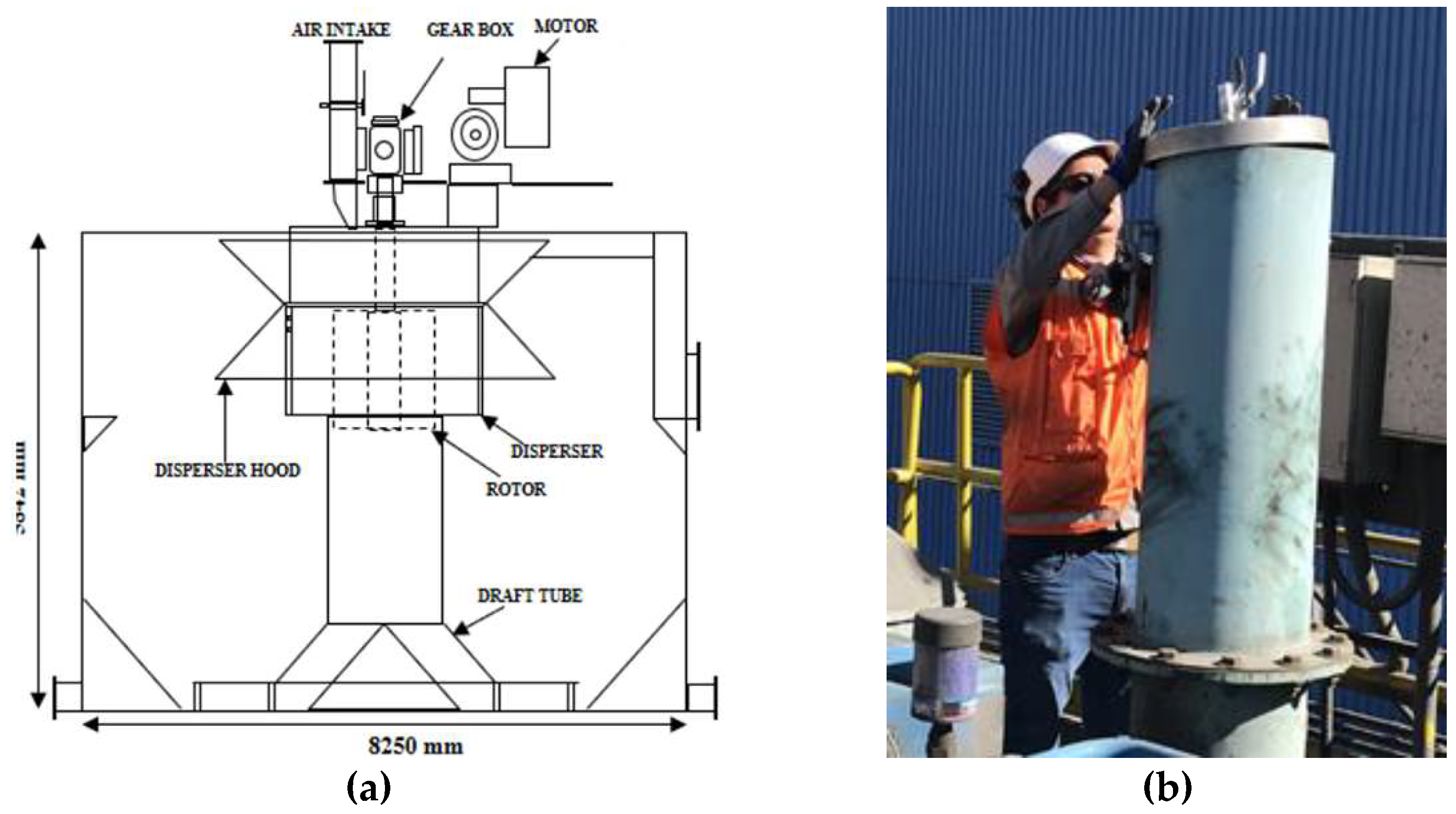
Figure 2(a) schematizes the main components of a 250 m
3 self-aspirated WEMCO cell at Los Pelambres.
Figure 2(b) shows a metallic cap with a ball valve installed on top of the air intake pipe to restrict the air injection. This setup was effective at modifying the gas holdup in the cell. Although this air obstruction allowed the air intake to be changed, the air flowrate was not regulated. Two individual cells were characterized according to the operational availability: (i) the second cell of bank A, and (ii) the seventh cell of bank C.
2.2. Gas holdup measurements
Gas holdup was measured using the JK Tech Air Holdup Probe [
23]. This sampler allowed for capturing one liter of aerated slurry. The sample was then poured into a graduated beaker to calculate the volume of the unaerated slurry. Gas holdup was determined from the difference between the sampler volume and that of the unaerated slurry. For each experimental condition, an average of four holdup measurements was obtained. The gas holdup was estimated when characterizing single cells and overall rougher banks, under restricted and non-restricted air intakes.
2.3. Axial solid profiles
To characterize the solid suspension in single cells, pulp samples were collected at different cell depths. These samples were taken at 70% of radial distance. The samples were analyzed in terms of the solid percentage and the particle size distribution. These measurements allowed characteristics of the solid suspensions to be determined with and without air restrictions.
2.4. Metallurgical assessment
Mass balances were conducted for the second cell of the rougher bank A and for the overall rougher banks A, C and D.
In single cells, the feed, concentrate, and tail streams were sampled. The dried samples were assayed to determine the copper grades and recoveries. These metallurgical indices were compared when activating or deactivating the air restriction. The concentrates were also analyzed by QEMSCAN (Quantitative Evaluation of Minerals by Scanning Electron Microscopy) to determine the impact of limiting the air inlet on the mineralogy and liberation patterns of these samples.
When characterizing the rougher banks, the recoveries registered from the Distributed Control System (DCS) were studied over a period of two months. During one week of this period, 11 cells of the rougher banks A, C and D were operated with air restriction. The comparison of the Cu recoveries with and without air restrictions allowed for the impact of limiting the air intake on the metallurgical performance to be determined. In addition, mass balances were conducted for banks A, C and D to determine size-by-size recoveries. The non-restricted condition was again compared to that with 11 cells operated with air restriction. The feed, concentrate and tailings of the rougher banks were sampled. Concentrates of the rougher banks C and D share the same launder, as shown in
Figure 1. The recoveries of these banks were then analyzed as a combined rougher stage. The dried samples were screened, and the finest classes were additionally classified by Cyclosizing. The screened samples were then assayed for Cu to obtain the respective size-by-size recoveries. These recoveries were compared, considering the non-restricted air condition (baseline) and two different air-restricted conditions.
3. Results and Discussion
3.1. Single cells assessment
This section describes the impact of restricting the air intake on the hydrodynamics and metallurgical performance of single WEMCO cells.
3.1.1. Hydrodynamic conditions in single flotation cells
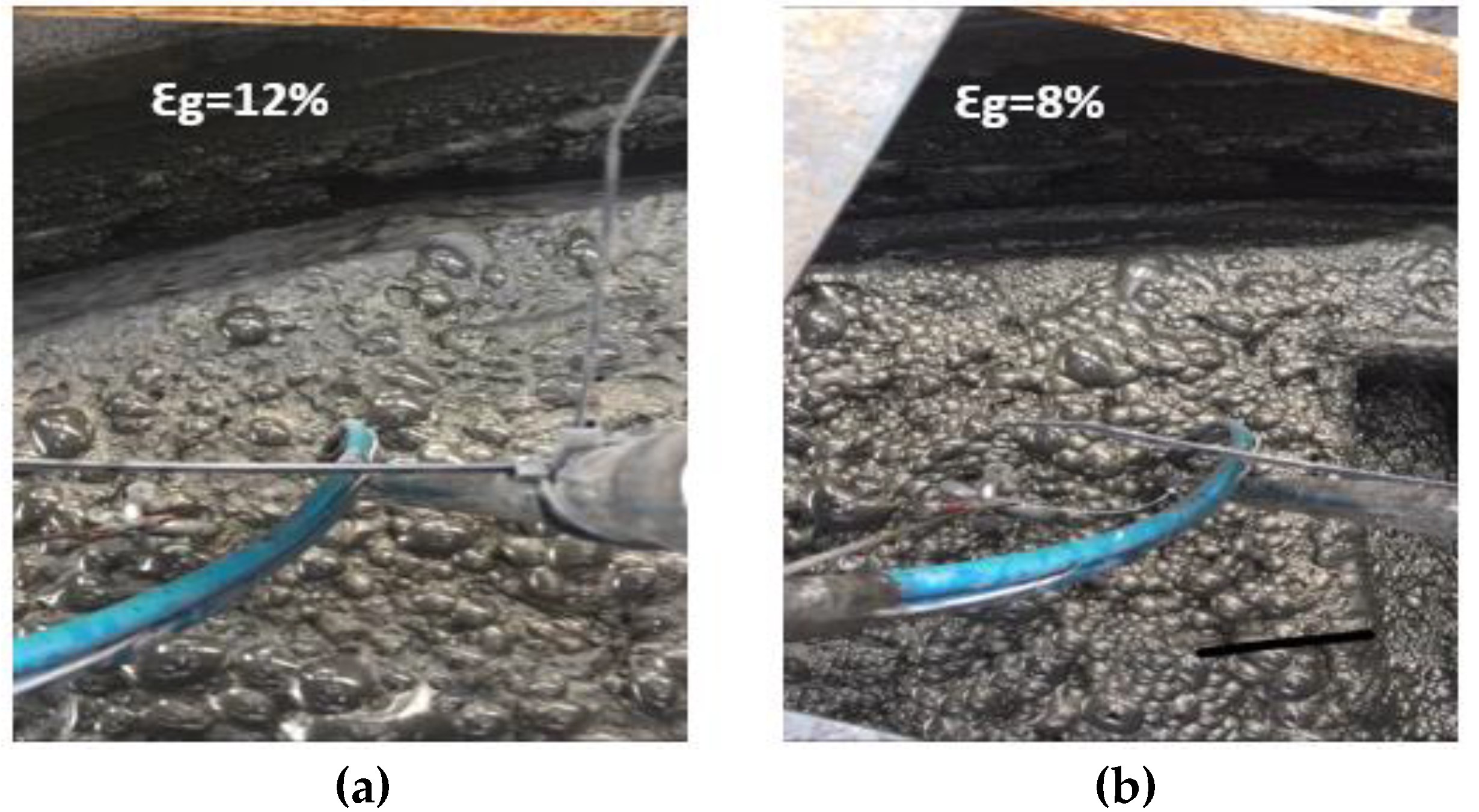
Figure 3 shows top-of-the-froth images obtained when the second cell of bank A was operated with no air restriction [baseline,
Figure 3(a)] and under air restriction [
Figure 3(b)]. A gas holdup reduction from 12% to 8% was observed from this change. The froth texture changed, leading to a a more stable and loaded froth for the air-restricted case. This preliminary observation showed the potential for air restriction to modify the metallurgical performance in single self-aspirated cells.
Concentrate samples were analyzed for solid concentration and particle size.
Table 1 summarizes the results in the second cell of bank A, in which particle size was quantified in terms of the P80. Significant increases in the solid concentration and particle size were observed for the concentrate sample, when this cell was operated under an air-restricted condition. A reduction in the water recovery followed by an increase in the solid concentration was expected when air intake was restricted, as gas holdup decreased. However, there was a significant increase in the P80. The decrease in air intake was hyphothesized to improve the pulp circulation, in agreement with the results reported in literature [
15,
16,
17] for forced-air machines, which increased the suspension of coarse particles, thus promoting their recovery.
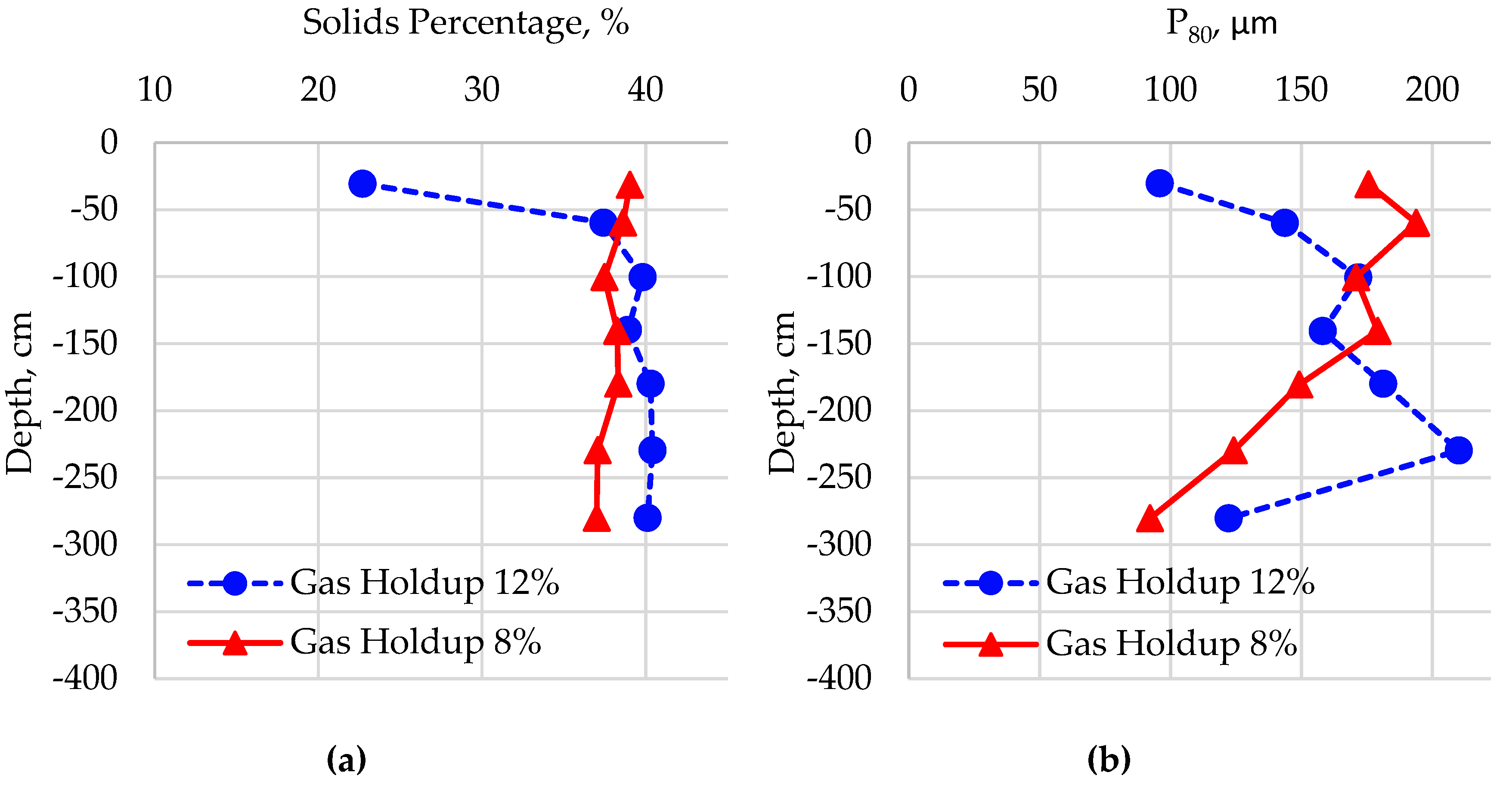
To further investigate these findings, pulp samples were taken at 70% of radial distance and at different depths inside the cell. These samples were analyzed for solid concentration and particle size.
Figure 4 shows the axial profiles for the solid percentage and particle size for the nominal and restricted-air conditions. In the former, a diluted zone underneath the pulp-froth interface was observed (dashed, blue line), exhibiting approximately 23% of solids and P80 ≈ 100 μm. When the air intake was restricted, the upper part of the cell experienced an increase in both, the solid concentration (~39% w/w) and P80 (~170 μm).
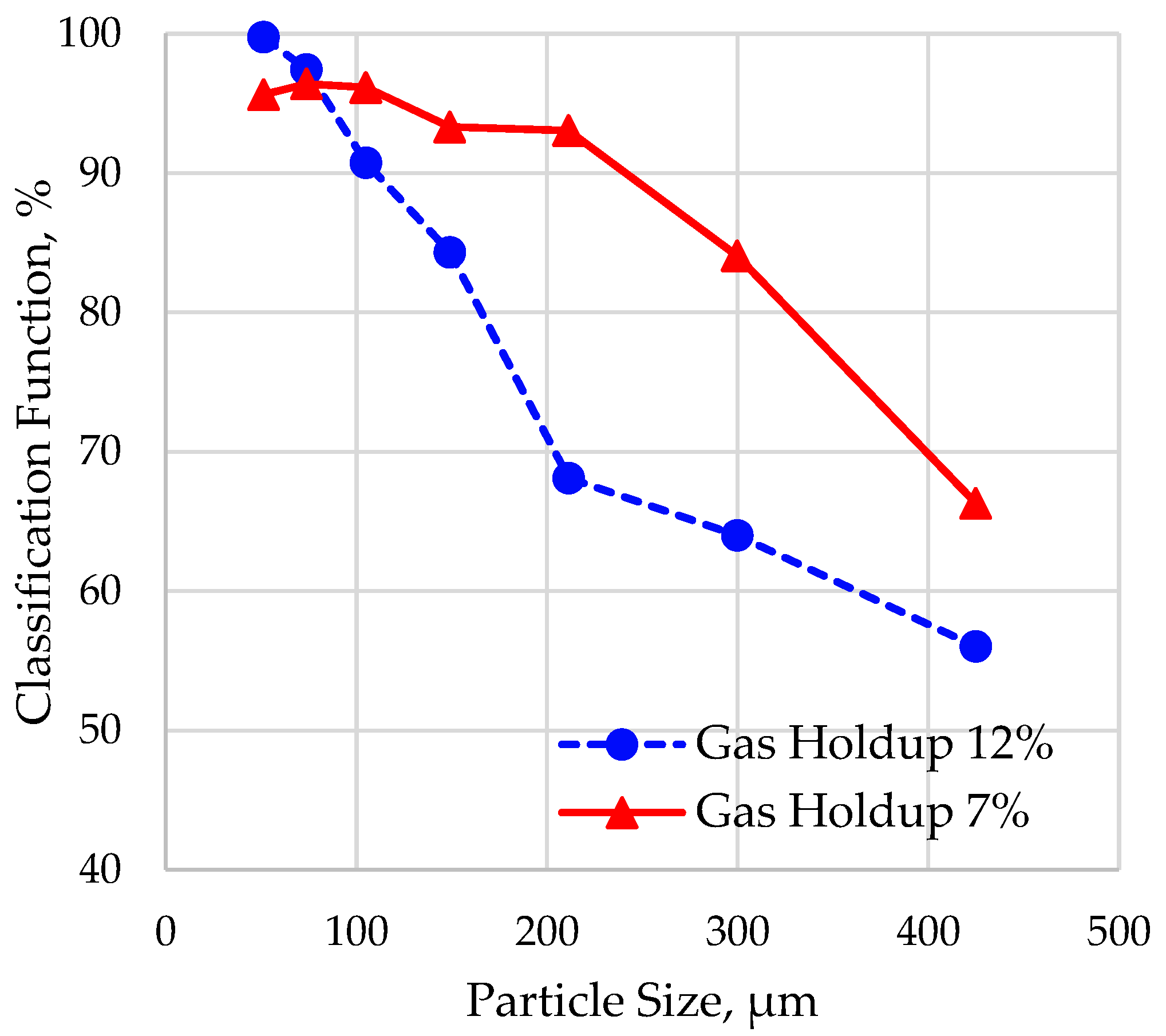
To better visualize the impact of restricting the air intake on the solids suspension in the WEMCO cell, the classification function proposed by Zheng, et al. [
24] was determined for the nominal and air-resctricted conditions. This function is calculated from the solid to water mass ratios, w
i, in a specific size class i, dividing the w
i values measured below the pulp-froth interface by the w
i values measured in the tailings. A flat classification curve implies no segregation, whereas a flat profile approaching 100% implies no segregation nor dilution. Pulp samples were then drawn from underneath the froth and the tailings of the cell seventh cell of bank C. For the unrestricted air condition, a gas holdup of 12 % was measured, which reduced to 7% when the suction pipe was obstructed.
Figure 5 compares the classification functions. Mixing was significantly improved over a wide range of particle sizes when restricting the air intake.
3.1.2. Metallurgical performance in single flotation cells
A significant change in WEMCO cell hydrodynamics was observed when the air intake was restricted. The impact of these changes on the metallurgical performance of a single cell was evaluated. Pulp samples of the feed, concentrate, and tailings of the second cell of bank A were taken and analyzed for solid concentration, particle size, and Cu grade.
Table 2 summarizes the results. The solid concentration and particle size of the concentrate samples increased once again for the air-restricted case.
Table 2 also shows an increase of 1.4% in the Cu recovery when restricting the air, compared to the baseline. This increase in recovery should be taken with some skepticism. The recovery calculation using the two-product formulae becomes sensitive to error propagation for cases where separation is poor, as is usually the case for single cells [
25,
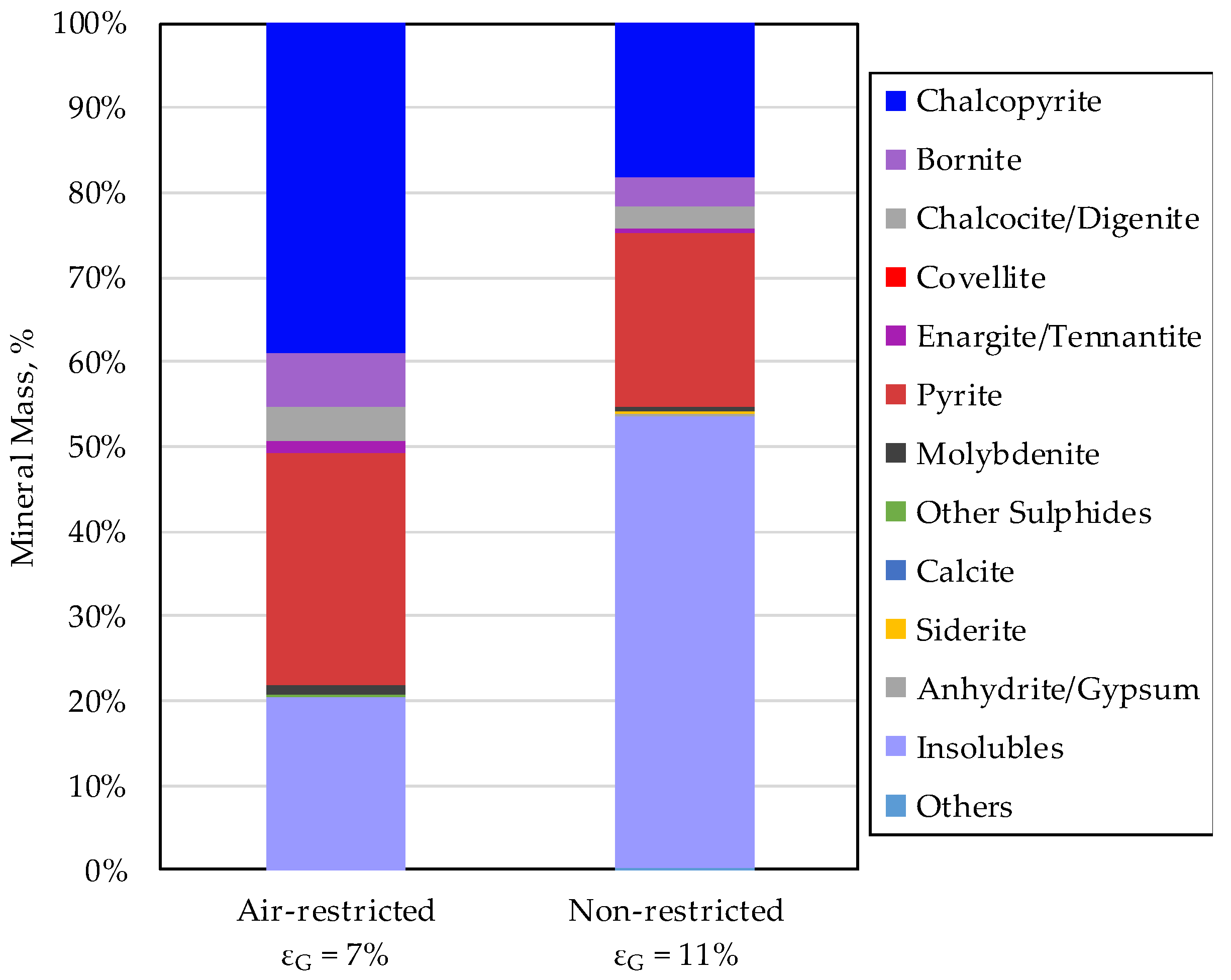
26]. An estimation of the water recovery revealed a reduction from 6.6% to 2.1% when changing the operation from non-restricted to air-restricted. This result implies a decrease of entrained particles, which was confirmed by conducting a mineral composition analysis of the concentrate samples.
Figure 6 shows a drastic reduction of more than 50% in the content of insoluble minerals, which justifies the increase in the concentrate grade (
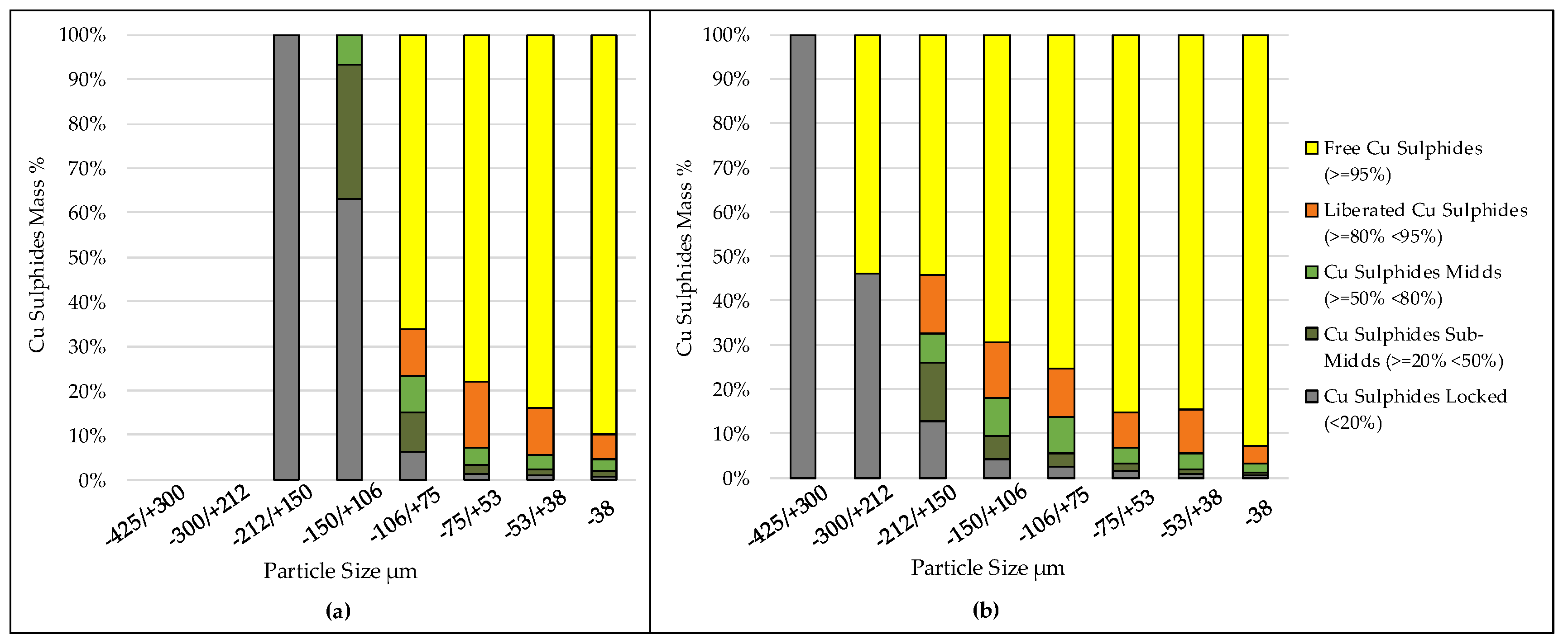
Table 2). Although, there are uncertainties in the estimated Cu recoveries, the QEMSCAN analysis of the concentrate samples revealed the presence of liberated coarse particles when the cell was air restricted [
Figure 7(b)]. These particles were not observed for the non-restricted case, as shown in
Figure 7(a).
3.2. Circuit assessment
This section describes the impact of restricting the air intake on the metallurgical performance of the rougher flotation circuit.
3.2.1. Overall rougher stage performance
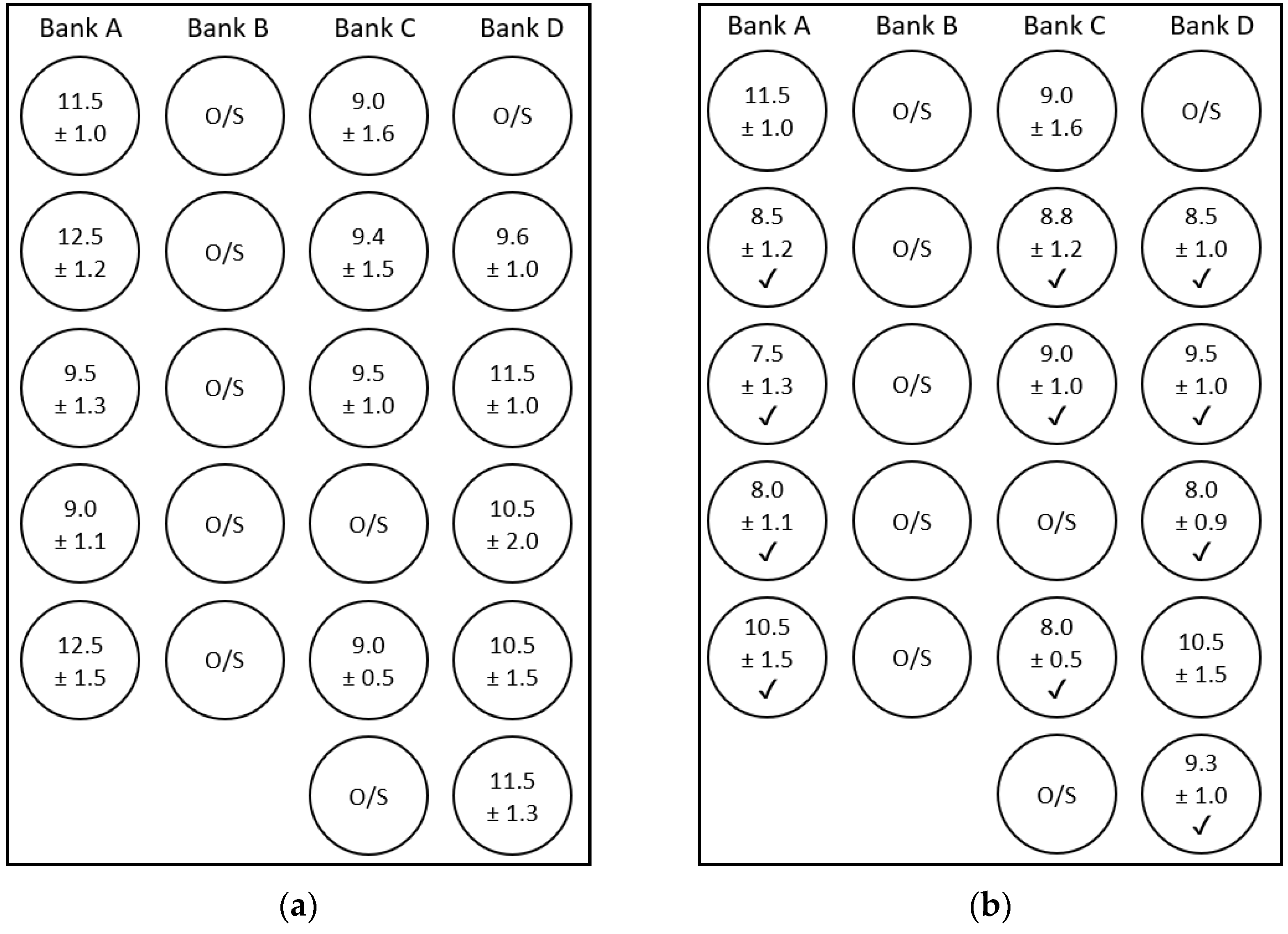
A sampling campaign was undertaken to quantify the impact of restricting the air intake, in multiple cells, on the overall rougher performance. Gas holdup measurements were again conducted for the unrestricted air condition (baseline), as shown in
Figure 8(a), and also for the restricted case [
Figure 8(b)]. The entire bank B, the first cell of bank D, and the fourth and sixth cells of bank C were out of service, which are labeled as O/S in
Figure 8. From
Figure 8(b), the air intake was restricted in eleven out of fourteen cells and highlighted by a checkmark. The average gas holdup reduction was almost -1.6% (absolute), only considering the manipulated cells. The air restriction was extended uninterruptedly for one week.
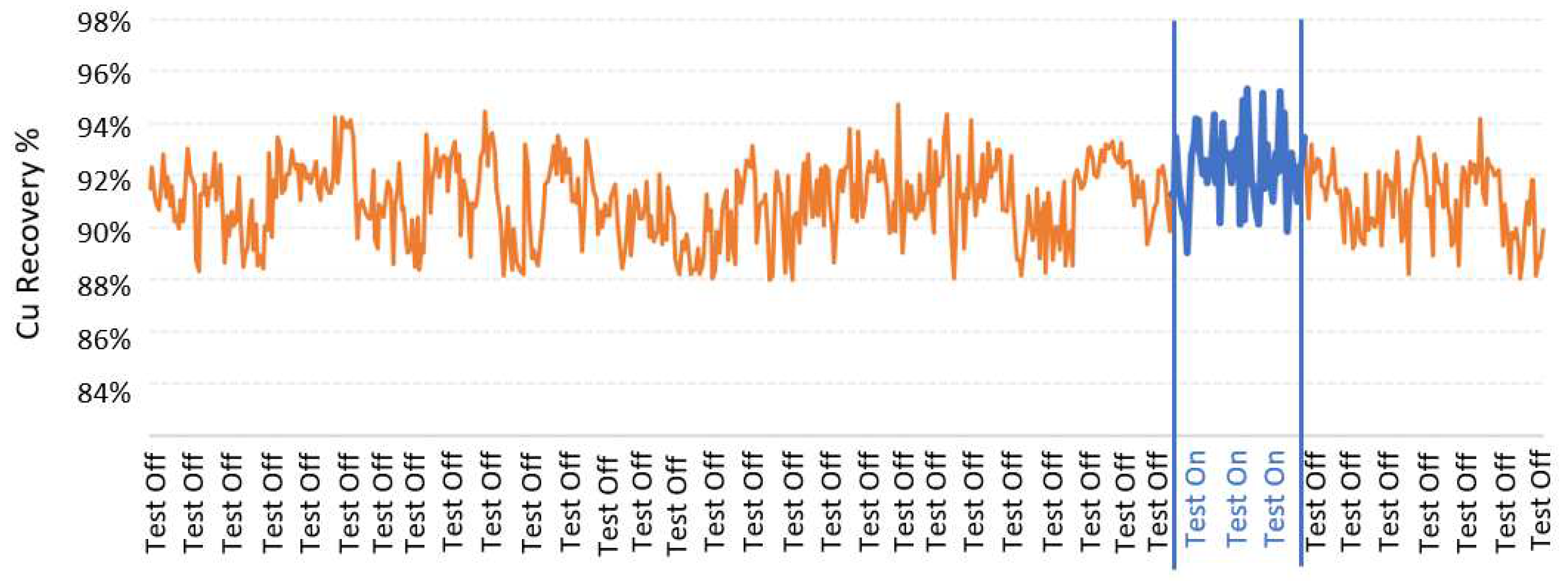
From the metallurgical assessment of the rougher bank, the Cu recovery exhibited an increase from 91.1% to 92.3% when the cells were operated under a restricted air intake.
Figure 9 shows the time series of Cu recovery for the metallurgical assessment conducted over 2 months). The blue range highlights the period operated under the restriction strategy, depicted in
Figure 8(b). The 95% confidence interval of the mean recovery difference (restricted minus non-restricted air) was 0.86%-1.62%, which implies that the observed differences were significant at α = 0.05. It should be noted that the air flowrate was not automatically regulated in each cell, nor a specific control strategy was developed along the banks. Despite this, an increase in rougher recovery was observed. This result suggests that the flotation performance can be improved by trading a reduction in the gas rate for an increase in the pulp circulation in the WEMCO cells.
3.2.2. Size-by-size rougher recoveries
Additional campaigns were conducted to determine size-by-size rougher recoveries for the conditions described in
Figure 8. The non-restricted condition was replicated 8 times to obtain a reference size-by-size recovery trend. In addition, the restriction scheme of
Figure 8(b) was tested under two conditions. The valve openings employed for the air obstruction were then manually modified to obtain two restriction levels. Banks C and D were assessed together as they share a concentrate launder. Bank A was assessed individually, as bank B was out of service. The results for bank A are summarized in
Appendix A.
Table 3 presents the average gas holdups for banks C and D when they were operated under the two air-restricted conditions. The non-restricted case is also presented as a reference.
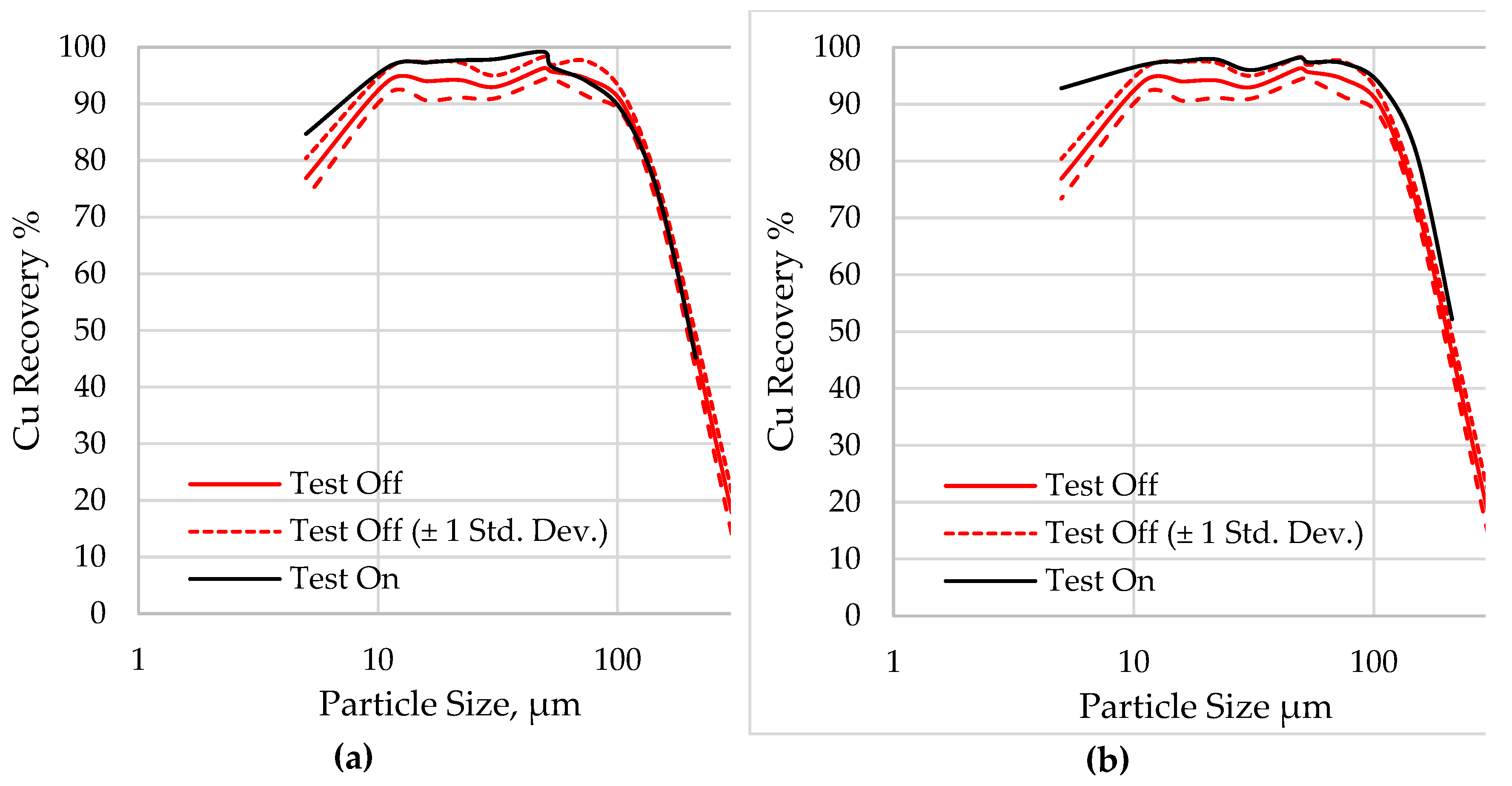
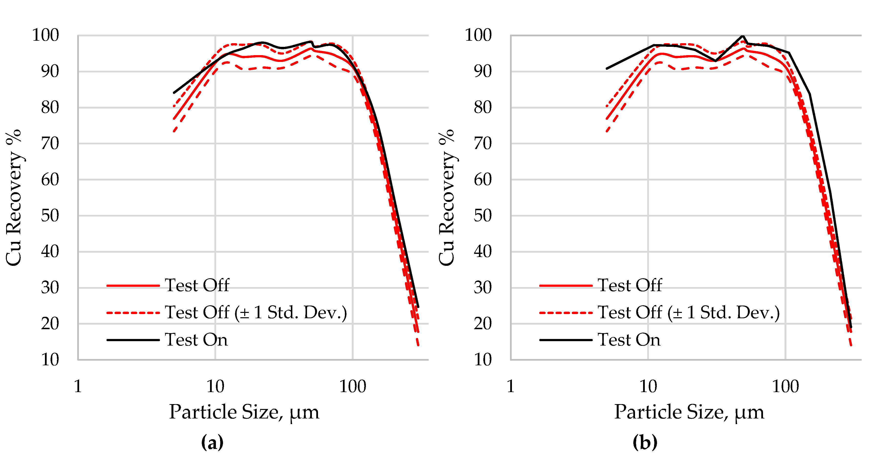
Figure 10 shows the size-by-size Cu recovery for the two levels of air restriction (Test On), compared to the non-restricted case (Test Off, baseline). A moderate increase in the recovery of fine and coarse particles is observed with respect to the baseline; however, these differences were more significant when the average change in gas holdup was higher [
Figure 10(b)]. The same trend was observed in bank A, as shown in
Figure A1 of
Appendix A. Although the results in single flotation cells indicated an improvement in the suspension of coarse particles, the size-by-size results in the rougher circuit show that this decrease also improved the recovery of fine particles after decreasing air injection. Thus, a slight reduction in the level of aeration in self-aspirated cells led to an increase in the Cu recovery, as shown in
Figure 9, which is justified by the simultaneous improvement in the recovery of fine and coarse particles.
Results from
Figure 4,
Figure 5,
Figure 6,
Figure 7,
Figure 8,
Figure 9 and
Figure 10show the potential of optimizing the air intake in self-aspirated cells to recover coarse particles. This finding agrees with those observed in forced air machines as reported in flotation literature [
15,
16,
17]. However, the size-by-size results in the rougher circuit indicate that the recovery of fine particles is also improved by restricting the air aspiration. Two possible mechanisms may have caused this improvement: (i) a decrease in bubble size; and (ii) an increase in impeller turbulence. Although both hypotheses seem feasible, a reduction in bubble size does not seem to be the main cause for the higher efficiency in the finer classes because the holdup decrease was only moderate when restricting the air. An increase in impeller turbulence seems more likely to improve the collisions between the fine particles and the bubbles, as less air favors the pulp circulation through the impeller. In addition, as the separation of low-grade ores is typically not constrained by carrying capacity limitations, the improvement in the pulp circulation through the impeller compensates for a lower bubble surface area flux.
From the results presented here, further developments are being made to determine the operating range for the air restriction that consistently leads to improvements in the metallurgical indexes of single cells. The potential of employing air restriction as a control variable in a regulatory control strategy is suggested as a research area to optimize existing flotation circuits consisting of self-aspirated cells.
4. Conclusions
This paper evaluated the hydrodynamic and metallurgical impact of restricting the air intake in self-aspirated flotation cells. Experiments were conducted at industrial scale, evaluating the performance of single cells and entire banks consisting of 250 m3 WEMCO machines. The main findings are summarized as follows:
An air intake restriction was viable in industrial self-aspirated machines. It was observed a consistent decrease in the gas holdup when restriction this intake. The air inlet obstruction was not regulated, and further developments are suggested on this subject.
The air restriction in single WEMCO cells led to a better suspension of coarse particles and a less diluted pulp below the pulp-froth interface, in agreement with results reported in literature for forced-air machines. This operational improvement increased the concentrate grade and slightly increased the Cu recovery at Los Pelambres concentrator.
The implementation of an air restriction strategy in a bank of cells proved to be feasible. By restricting the air intake in eleven out of fourteen cells, in 3 rougher banks, the Cu recovery increased 0.9%-1.6% at a 95% confidence level in this stage.
The improvement in the rougher bank recoveries was justified by an improvement in the separation of coarse particles, but also by an improvement in the recovery of fine particles. The air restriction increased the turbulence that favored the interactions between the bubbles and fine particles. Thus, a regulation of the air intake has the potential to be used for control purposes.
Adequate instrumentation and regulatory control loops are recommended for the air intake in self-aspirated flotation cells, which will improve the flotation performance of existing circuits. These components will be the foundations to develop optimizing strategies for arrangements of cells in series at industrial scale.
Author Contributions
Conceptualization, M.M.G. and M.M.S.; methodology, M.M.G. and M.M.S.; software, M.M.G., M.M.S. and L.V.; validation, M.M.G., M.M.S. and L.V.; formal analysis, M.M.G. and M.M.S.; investigation, M.M.G. and M.M.S.; resources, M.M.S. and L.V.; data curation, M.M.G., M.M.S. and L.V.; writing—original draft preparation, M.M.G., M.M.S. and L.V.; writing—review and editing, M.M.G., M.M.S. and L.V.; visualization, M.M.G., M.M.S. and L.V.; supervision, M.M.S.; project administration, M.M.S. and L.V.; funding acquisition, M.M.S. and L.V. All authors have read and agreed to the published version of the manuscript.
Funding
Miguel Maldonado would like to acknowledge support from the Chilean Council of Science and Technology through the project ANID/Fondecyt 1211705. Luis Vinnett would like to acknowledge support from Universidad Técnica Federico Santa María, Project PI_LIR_23_02.
Conflicts of Interest
There is no conflict of interest.
Table A1 presents the average gas holdup in bank A when operated under two air-restricted conditions. The non-restricted condition is also presented.
Figure A1 shows the size-by-size Cu recovery for the two levels of air restriction (Test On), compared to the non-restricted case (Test Off, baseline). The same size-by-size trends observed in the rougher banks C and D were found in the rougher bank A, confirming the potential to improve the recovery of coarse and fine particles by optimizing the air intake.
Table A1.
Average gas holdup for bank A for two air-restricted conditions and for the non-restricted case.
Table A1.
Average gas holdup for bank A for two air-restricted conditions and for the non-restricted case.
| Average Gas Holdup for Banks C and D |
| Non-restricted |
Air-restricted |
Difference |
| 10.6% |
9.4% |
-1.2% |
| 10.6% |
8.7% |
-1.9% |
Figure A1.
Size-by-size Cu recoveries in the rougher bank A, comparing the air-resticted case with the non-restricted scenario: (a) a low average air-restriction (a decrease in 1.2% in the average gas holdup with respect to the non-restricted case), (b) a moderate average air-restriction (a decrease in 1.9% in the average gas holdup with respect to the non-restricted case).
References
- Maldonado, M.; Araya, R.; Finch, J. An overview of optimizing strategies for flotation banks. Minerals 2012, 2, 258–271. [Google Scholar] [CrossRef]
- Maldonado, M.; Sbarbaro, D.; Lizama, E. Optimal control of a rougher flotation process based on dynamic programming. Minerals engineering 2007, 20, 221–232. [Google Scholar] [CrossRef]
- Bellman, R. Dynamic programming. Science 1966, 153, 34–37. [Google Scholar] [CrossRef] [PubMed]
- Aris, R. Discrete Dynamic Programming: an introduction to the optimization of staged processes, 1st ed.; Blaisdell Publishing Company: New York, NY, USA, 1964.
- Gorain, B. Optimisation of flotation circuits with large flotation cells. Proceedings of Centenary of Flotation Symposium, Brisbane, QLD, Australia, Year; pp. 843–851.
- Hadler, K.; Cilliers, J. The relationship between the peak in air recovery and flotation bank performance. Minerals Engineering 2009, 22, 451–455. [Google Scholar] [CrossRef]
- Cooper, M.; Scott, D.; Dahlke, R.; Finch, J.; Gomez, C. Impact of air distribution profile on banks in a Zn cleaning circuit. CIM Bulletin 2004, 97, 1–6. [Google Scholar]
- Aslan, A.; Boz, H. Effect of air distribution profile on selectivity at zinc cleaner circuit. Minerals Engineering 2010, 23, 885–887. [Google Scholar] [CrossRef]
- Seguel, F.; Soto, I.; Krommenacker, N.; Maldonado, M.; Becerra Yoma, N. Optimizing flotation bank performance through froth depth profiling: Revisited. Minerals Engineering 2015, 77, 179–184. [Google Scholar] [CrossRef]
- Bergh, L.; Yianatos, J. Control of rougher flotation circuits aided by industrial simulator. Journal of Process Control 2013, 23, 140–147. [Google Scholar] [CrossRef]
- Maldonado, M.; Araya, R.; Finch, J. Optimizing flotation bank performance by recovery profiling. Minerals Engineering 2011, 24, 939–943. [Google Scholar] [CrossRef]
- Singh, N.; Finch, J. Bank profiling and separation efficiency. Minerals Engineering 2014, 66, 191–196. [Google Scholar] [CrossRef]
- Finch, J.A.; Tan, Y.H. Flotation bank profiling revisited. Minerals Engineering 2022, 181, 107506. [Google Scholar] [CrossRef]
- Degner, V.R. Recent WEMCO flotation technology advancements. Resources Processing 1988, 35, 79–96. [Google Scholar] [CrossRef]
- Arbiter, N.; Harris, C.; Yap, R. The air flow number in flotation machine scale-up. International Journal of Mineral Processing 1976, 3, 257–280. [Google Scholar] [CrossRef]
- Lima, O.A.d.; Deglon, D.A.; Leal Filho, L.d.S. A comparison of the critical impeller speed for solids suspension in a bench-scale and a pilot-scale mechanical flotation cell. Minerals Engineering 2009, 22, 1147–1153. [Google Scholar] [CrossRef]
- Van der Westhuizen, A.; Deglon, D. Evaluation of solids suspension in a pilot-scale mechanical flotation cell: The critical impeller speed. Minerals Engineering 2007, 20, 233–240. [Google Scholar] [CrossRef]
- Hassanzadeh, A.; Safari, M.; Khoshdast, H.; Güner, M.K.; Hoang, D.H.; Sambrook, T.; Kowalczuk, P.B. Introducing key advantages of intensified flotation cells over conventionally used mechanical and column cells. Physicochemical Problems of Mineral Processing 2022, 58. [Google Scholar] [CrossRef]
- Yianatos, J.B.; Larenas, J.M.; Moys, M.H.; Diaz, F.J. Short time mixing response in a big flotation cell. International Journal of Mineral Processing 2008, 89, 1–8. [Google Scholar] [CrossRef]
- Schwarz, M.P.; Koh, P.T.L.; Wu, J.; Nguyen, B.; Zhu, Y. Modelling and measurement of multi-phase hydrodynamics in the Outotec flotation cell. Minerals Engineering 2019, 144, 106033. [Google Scholar] [CrossRef]
- Schwarz, M.; Koh, P.; Yang, W.; Nguyen, B. Investigation of the gas-liquid-particle multi-phase hydrodynamics of Wemco flotation cells. Minerals Engineering 2022, 179, 107388. [Google Scholar] [CrossRef]
- Henríquez, F.; Maldonado, L.; Yianatos, J.; Vallejos, P.; Díaz, F.; Vinnett, L. The Use of Radioactive Tracers to Detect and Correct Feed Flowrate Imbalances in Parallel Flotation Banks. J 2022, 5, 287–297. [Google Scholar] [CrossRef]
- Schwarz, S.; Alexander, D. Gas dispersion measurements in industrial flotation cells. Minerals Engineering 2006, 19, 554–560. [Google Scholar] [CrossRef]
- Zheng, X.; Franzidis, J.-P.; Johnson, N.; Manlapig, E. Modelling of entrainment in industrial flotation cells: the effect of solids suspension. Minerals Engineering 2005, 18, 51–58. [Google Scholar] [CrossRef]
- Wills, B.A.; Finch, J. Wills' mineral processing technology: an introduction to the practical aspects of ore treatment and mineral recovery; Butterworth-Heinemann: Oxford-Waltham, 2015. [Google Scholar]
- Vinnett, L.; Yianatos, J.; Flores, S. On the mineral recovery estimation in Cu/Mo flotation plants. Minerals & Metallurgical Processing 2016, 33, 97–106. [Google Scholar] [CrossRef]
|
Disclaimer/Publisher’s Note: The statements, opinions and data contained in all publications are solely those of the individual author(s) and contributor(s) and not of MDPI and/or the editor(s). MDPI and/or the editor(s) disclaim responsibility for any injury to people or property resulting from any ideas, methods, instructions or products referred to in the content. |
© 2023 by the authors. Licensee MDPI, Basel, Switzerland. This article is an open access article distributed under the terms and conditions of the Creative Commons Attribution (CC BY) license (http://creativecommons.org/licenses/by/4.0/).
