
Submitted:
27 September 2023
Posted:
28 September 2023
You are already at the latest version
Abstract
Here, we investigate the actuation dynamics of a micro device with different intervening liquids between the actuating components under the influence of Casimir and dissipative hydrodynamic forces. This is enabled via phase space portraits, which demonstrate that by increasing the dielectric response of the intervening layer the device may not come into stiction due to the decreasing in magnitude Casmir force. Moreover, it is feasible to expand area of motion using intervening liquids with lower dynamic viscosity or increasing the slip length of the intervening fluid. Finally, under the influence of an external driven force, which is the realistic case for possible applications, the system can reach stable oscillation at larger separations with an amplitude higher for the liquid that lead to lower Casimir and hydrodynamic forces.
Keywords:
Casimir effect
; Actuation dynamics
; MEMS
; NEMS
; Stiction
I. Introduction
During the past decades the emergence of rapid development in micro/nano fabrication has led to scaling down of electromechanical systems into submicron length scales. This opens new areas for the application of the Casimir forces, since they could inevitably play role in the operation of micro/nano systems [1,2,3,4,5,6,7,8]. These devices have sufficiently large surface areas and gaps small enough for the Casimir force even to pull components together leading to permanent adhesion, a phenomenon known as stiction [9,10,11,12]. And this malfunction is in many cases unavoidable for the dynamical stability of micro/nano electromechanical systems (MEMS/NEMS) such as sensors, micro switches, actuators. Hence, a comprehensive knowledge about the magnitude and direction of the Casimir force can provide strong insight into the design and architecture of MEMS/NEMS.
The Casimir force, which originates from perturbations of fluctuating electromagnetic (EM) fields [13,14], was discovered in 1948 by the Dutch physicist Hendrick Casimir [15]. This is a quantum mechanical attractive force between two parallel, neutral, and perfectly conducting flat plates and without considering thermal fluctuations (T=0 K) [15]. In 1950’s, Evgeny Lifshitz and co-workers proposed the general theory for the Casimir force between parallel flat plates made of real dielectric materials [16]. For this purpose, it was utilized the fluctuation– dissipation theorem to relate the dissipative properties of the plates (optical absorption by many microscopic dipoles) and EM fluctuations. The Lifshitz theory predicts the attractive force between the two parallel plates of arbitrary materials, and covers both at short ranges (non-retarded regime) the van der Waals forces, and at longer ranges (retarded regime) the Casimir forces. [16,17].
Furthermore, the Lifshitz theory enables the prediction of the actuation dynamics of micro/nano devices actuation, since the omnipresent Casimir force could play significant role. This because the Lifshitz theory allows to compute the tuning of the Casimir force, in principle, for both the magnitude and direction, by a suitable choice of the interacting materials with the necessary optical properties [18,19,20,21]. As a result, several studies have been performed on the effect of optical properties on the actuation dynamic of devices in order to widen the range of their applications [22,23,24,25]. For example, in [23] was illustrated how the use of phase change materials can delay chaotic motion in MEMS without changing the materials. Also, in [24] was investigated how one can decrease the influence of the temperature on the magnitude of the Casimir force with the use of suitable materials in order to survive operation at low or high temperatures. Finally, in [25] was demonstrated how the magnetoelectric effect in micro devices consisting of topological insulators can become dominant on the operation of MEMS, and taking into account its sensitive dependence on thermal fluctuations.
In fact, a three-layer system consisting of two actuating components immersed inside a liquid has attracted extensive attention because it provides unique advantages. In this system, under certain conditions, it is possible to generate repulsive Casimir forces leading to stable operation without employing a restoring mechanical spring [28,29,30,31,32,33,34,35,36]. Moreover, with a ferrofluid between the actuating components one can open new opportunities in nanotechnology [29], for instance, in micromechanical sensors [30], microfluidics [31,32], and microrobotics [33]. Therefore, we have considered here a MEMS operating inside a fluid, and the main aim is to investigate how stable operation is sensitive to optical properties of the intervening layer by taking also into account the dynamic viscosity of the intervening fluids as well as the fluid slip length on the walls of the actuating plate. Hence, the results presented in this study are essential for studying the dynamical behavior of MEMS and their design in liquid environments.
II. Methods and materials
Here we have assumed that the actuating components of the MEMS device are coated with Au, which is a good conductor. The latter has static conductivityeV [34] (ωp and ωτ define the plasma and relaxation frequencies respectively), and it is also extensively used for Casimir force measurements. Moreover, ethanol and kerosene are used as the intervening layer between the Au plates. Previous studies have shown that ethanol could produce repulsive Casimir forces in a system consisting of different interacting bodies (with dielectric functions εLiquid, ε1, ε2, respectively) if the condition ε1<εLiquid<ε2 is satisfied [26,27,28], and kerosene is also used in ferrofluid-based microdevices. In any case, both materials, as an intervening medium, have attracted attention in investigations related to Casimir forces [29,30,31,32,33]. The dielectric response of ethanol at imaginary frequencies can be described by a three-oscillator Ninham-Parsegian model [29]:
where n0=1.35 is the refractive index in the visible range, ε0=25.07 is the static dielectric constant, and εIR=4.2 is the dielectric constant where the microwave (MW) relaxation ends and the infrared (IR) begins. ωMW=6.97×10⁹ rad/s, ωIR=2.588×10¹⁴ rad/s, and ωUV=1.924×10¹⁶ rad/s are the characteristic MW, IR, and ultraviolet (UV) absorption frequencies, respectively. Similarly, we have for the dielectric function of kerosene at imaginary frequencies [29]:
where the second term on the right-hand side describes the contribution to the dielectric permittivity from the orientation of permanent dipoles. The values of B=0.020 and 1/τ = 8.0 × 10⁸ rad/s were determined from the measured data of Ref. [34] in the MV region. The third term shows the effect of ionic polarization with CIR=0.007 and ωIR = 2.14 × 10¹⁴ rad/s as obtained using the infrared optical data of Ref. [35]. The fourth term describes the optical data in the UV region with the values CUV=0.773 (obtained from the static dielectric permittivity at zero frequency εK=1.8 [34] since εK=1+B+CIR+CUV) and ωUV=1.0×10¹⁶ rad/s. Finally, the dielectric functions of all media at imaginary frequencies, which are vital as input for the calculations of the Casimir force via the Lifshitz theory, are shown in Figure 1a.
The dielectric function ε (i𝜉) is vital input to compute the Casimir force using the Lifshitz theory [16]. In fact, the Casimir force between two parallel plates at T=300k is given in terms of the Lifshitz theory (at the imaginary frequency representation) by the equation
where describes the imaginary frequencies (=). is Planck constant, k defines Boltzmann constant, and the prime in the sum of Eq. (3) means that the n=0 term must be taken with half weight. The term describes the multiple reflections from the inner surfaces of the interacting bodies, which is represented by the equation
The Fresnel reflection coefficients are given by:
and
for the s or transverse electric polarization (TE), and p or transverse magnetic polarization (TM) of the electromagnetic field, respectively. ε0 (i𝜉) and εi (i𝜉) are the dielectric functions of the intervening layer and the interacting components respectively. (i=0,1,2) describes the out-off plane wave vector in the intervening layer between the interacting components (), and in each of the interacting components (), and q is the in-plane wave vector.
Furthermore, we have considered a typical MEMS, which is shown in the inset of Figure 1a, consisting of two plates with the upper one being able move. Both components are assumed to be coated by Au, (with coating thickness of more than 100 nm in order to be considered optically bulk material) [36]. Moreover, we have assumed flat plates because at short separations (<100 nm) nanoscale roughness can affect significantly the Casimir force. The initial distance of the parallel plates is assumed to be d=300 nm, and the system temperature being T=300 K. The intervening medium between these components is assumed to be ethanol or kerosene. The equation of motion for the MEM system without any external driven force is given by
where M is the mass of the moving plate. The term (𝑀/𝑄) (𝑑 /𝑑𝑡) describes the Stokes term for the energy losses of the moving plate, Q defines the quality factor of the MEMS (in this study is considered to be Q=400 while calculations performed with low values of Q=10 do not have significant effect). We also assumed =300kHz which is a typical frequency for AFM cantilevers and MEMS [37]. =-k(d-z) is the restoring force with k the elastic spring stiffness, and is the Casimir force, which is computed via the Lifshitz theory (see Appendix). Finally, Fh defines the separation dependent hydrodynamic force, which is the dominant dissipation term due to its 1/z dependence at short separations, and it is given by [38,39,40,41,42,43,44,45,46,47]
where A is area of the plates, and we have considered for both the length (Lx) and width (Ly) of the plates the value of 10μm. μ is the dynamic viscosity of the intervening liquid. The latter at 300 K has the value μ=0.001 Kg/ms and μ=0.0016 Kg/ms for ethanol and kerosene, respectively. 𝑓∗ is the correction due to deviations from the Reynolds flow because of fluid slip on solid surfaces (see Fig. 1b). In this study we have considered the same slip length b on the surface of both plates. If b=0 then 𝑓∗=1, otherwise it is given by [38,39,40,41,42,43,44,45,46,47]
Equation (5) is valid for fluid flow with low Reynolds numbers, and short separations between the interacting components.
III. Results and discussion
Before analyzing the actuation dynamics, we will illustrate the influence of the optical properties of intervening layer on the Casimir force via Lifshitz theory calculations. In order to achieve our aim, we introduce the reduction factor 𝜂p𝑝(𝑧) (<1) to normalize the Casimir force with respect to the maximum Casimir force (FC=π2ħc/240z4) [15] between ideal metals at T=0K. The Casimir force calculations are shown in Figure 2, and confirm that by increasing the magnitude of the dielectric function ε(i𝜉) of the intervening layer (since εAu(i𝜉) >εethanol(i𝜉) > εkerosene(i𝜉)) the strength of the Casimir force is reduced.
Furthermore, for the discussion of the actuation dynamics for the three-layer micro device it is helpful to consider the separation 𝑧∗, where there is equilibrium between the Casimir and the restoring forces or 𝐹𝐶 (𝑧∗) + 𝐹res (𝑧∗) =0. The latter yields the characteristic spring stiffness K∗ = 𝐹𝐶(𝑧∗)/ (d − 𝑧∗). d defines the initial separation between plates where the spring is supposed to be unstretched (d= 300nm). Indeed, K∗ determines the minimum spring stiffness for the system to be able to sustain some form of motion against stiction of the moving component on the fixed plate.
In the beginning, in order to show how the presence of the hydrodynamic drag force can change the motion, and consequently the phase portrait, we have considered a micro device which is placed in vacuum or air. Under these conditions, the energy dissipation is described only by the Stokes dissipation term (Mω0/Q) (dz/dt), where the values of the Q factor considered here are typical for a multitude of MEMS/NEMS operating in vacuum [4,37]. Figure 3 shows the corresponding phase portraits for a microsystem consisting of Au coated components that are placed in vacuum. As it can be seen in Figure 3a, when the stiffness of the restoring force is sufficiently strong the phase portrait reveals closed orbits, which correspond to periodic motion around a stable center equilibrium point. Also, by decreasing the magnitude of the restoring force for lower stiffness, the size of orbits enlarges allowing the moving plate to come rather close to the fixed plate and preserve its stable operation. Notably, the stable operation can be preserved until the restoring force is stronger than the force corresponding to K∗ for a considered initial condition. Hence, if the restoring force becomes smaller than force corresponding to K∗ there is no more closed orbit. In fact, according to Figure 3b, by considering a weak value of the restoring force (K< K∗), it can be seen the close orbit changes into an open orbit, which is the evidence of motion of the moving plate towards the fixed one leading to irreversible adhesion between the components. This a phenomenon, which is called stiction. If, however, it is increased the dissipation energy, or equivalently decrease the quality factor Q, then it is still possible to decrease the possibility to drive the system into stiction. The effect of the finite value of Q, due to intrinsic and extrinsic dissipation mechanisms of the oscillating plate, is shown in Figure 3b. Indeed, calculations illustrate that the transition from unstable motion towards stiction to stable oscillation is possible if dissipative motion can take place. Therefore, proper tuning of the system Q factor can also aid to prevent the permanent adhesion of an otherwise unstable micro system.
In previous Figure 3a and 3b was considered as an initial condition (z=0.95d) and different values of the stiffness for the restoring force (K<K* and K>K*). In Figure 3c, we have assumed a fixed stiffness K (which is correspond to z=0.95d), and we considered different initial conditions. According to Figure 3c there is homoclinic orbit including one unstable equilibrium point on the sharp side of the orbit and one stable equilibrium inside it. This homoclinic curve can sharply separate unstable motion (leading to stiction within one period) from the periodic closed orbits around the stable center point. Any solution of the equation of motion with initial conditions within the homoclinic orbit that goes until the unstable saddle point (square in shape in Figure 3c) will lead to stable periodic motion around the stable center. However, for any other initial conditions outside of the homoclinic orbit, the upper plate will perform unstable motion leading to collapse on the fixed plate. In the latter case, the micro system is unstable during oscillation around these points due to the stronger Casimir force leading to the collapse of the moving plate on the fixed one, which is the well-known situation termed as stiction. Clearly, the periodic solutions indicate that the restoring force is strong enough to keep system in operation and avoid any stiction instabilities.
Furthermore, we have considered the three-layer microsystem consisting of Au coated components within a liquid (ethanol or kerosene) playing the role as an intervening layer. In this system, besides the Stokes dissipation term (Mω0/Q) (dz/dt), the additional hydrodynamic force describes also dissipation for the micro system, and consequently can play inevitable role for the motion and phase portrait of these devices. In this case, it is shown that the phase portraits related to the autonomous micro device containing liquid do not reveal closed orbits or equivalently continuous oscillation. Unlike the micro device which is placed in vacuum, even by considering a sufficiently strong restoring force, the phase portraits show a spiral trajectory which eventually stops at the resting position z=d. This is shown in the calculations of Figure 4, where we have considered as an initial position λ* (=𝑧∗/d) =0.5 to activate the actuation. If the spring stiffness is 𝐾>K∗ then for both micro systems the moving component approaches slowly the resting position toward z=d and eventually stops. By considering 𝐾>>K∗ the corresponding curve in phase space illustrates that the moving component exhibits stronger velocity due to the enhancement of the restoring force. For value of K<K∗ the moving component eventually collapses on fixed plate leading to permanent adhesion or stiction.
Furthermore, Figure 5 shows phase space portraits using as initial condition λ∗=0.5 and significant spring stiffness 𝐾>>K∗ leading to spiral trajectory towards finally immobility. By increasing the restoring force, the spiral curve and consequently the velocity of the moving component becomes wider. By increasing also, the slip length b, the hydrodynamic dissipation, which acts against the motion, reduces and as a consequence the spiral trajectory is more extended for both liquids. However, the effect of the slip length (b), as the spring stiffness increases, becomes more pronounced for the micro system containing kerosene for which the Casimir force is stronger than that of micro system containing ethanol as it is shown also in Figure 2. In any case, both micro systems preserve the ability to move if the spring stiffness K is stronger than the value that corresponds to λ∗ ( and for micro system containing ethanol and kerosene, respectively), while for both micro systems stiction occurs if K<K∗. Although the hydrodynamic force cannot influence the magnitude of K∗ (which depends on the magnitude of the Casimir force), this term is significantly important in phase space. Indeed, as Figure 6 shows, for 𝐾<K∗ the reduction of the hydrodynamic force causes the approach to stiction to take place significantly faster. Therefore, increasing the slip length (b), or equivalently decreasing the hydrodynamic dissipation in the system containing kerosene, it is possible to make the trajectory of both micro systems similar to each other (Figure 6b).
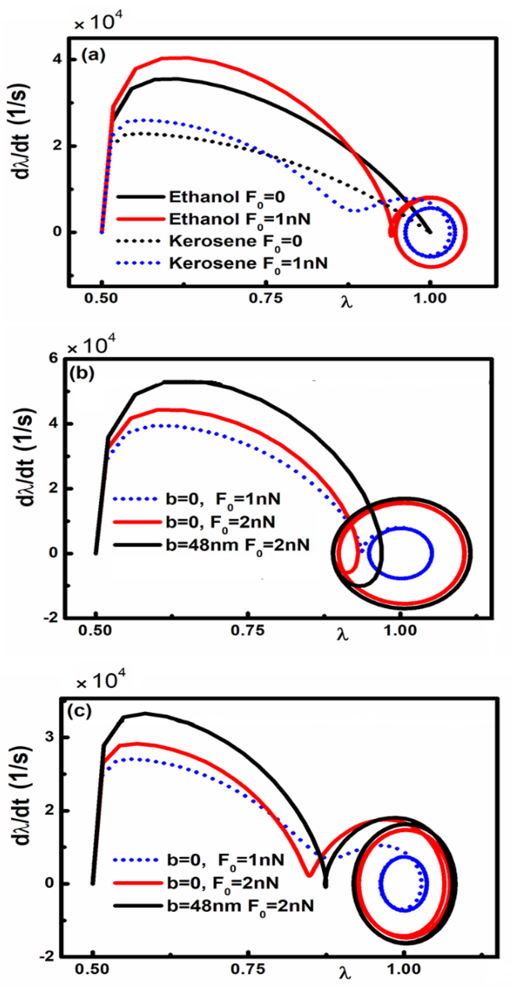
Finally, we have investigated in Figure 7 the response of the three layer micro device with a liquid as an intervening medium under the presence of an external driven periodic force ( F(t)= F0cos(ωd t)), which is the realistic case for possible applications. In this case the equation of motion has the more general form as:
By decreasing the magnitude of the Casimir force (for large value of λ or equivalently larger separations) and the hydrodynamic force, the influence of the periodic driven force becomes dominant and micro system can achieve continious stable oscillation around the resting position (z=d). Indeed, acording to Figure 7a, the amplitude of the stable oscillation is higher for micro system containing ethanol due to the lower magnitude of Casimir and hydrodynamic forces. This is also depicted in Figure 7b and 7c, where the amplitude of the continuos oscillation is smaller in micro system containing Kerosene due to stronger magnitude of the Casimir force and hydrodynamic force. Moreover, as Figure 7b and 7c indicate, an increasing amplitude of the external driven periodic force (Fo ) leads to significant influence on the continious oscillation, while deacreament of the hydrodynamic force (by increasing slip length) is no longer making significant difference on the oscillatory motion for both liquids.
IV. Conclusions
In this study, we investigated the actuation dynamics of a micro device consisting of Au coated components with different intervening liquids between the actuating components under the influence of Casimir and separation dependent dissipative hydrodynamic drag forces. This is accomplished via phase space portraits, which demonstrate that by increasing the dielectric response of the intervening layer could prevent the microdevice to come into stiction due to decreasing in magnitude Casmir forces. Using the phase portraits of a microsystem that is placed in vacuum or air, it has been shown how the presence of a liquid and as a consequence the additional dissipation term due the position dependent hydrodynamic drag force can significantly influence the actuation dynamics of MEMS/ NEMS. By assuming vacuum or air between the actuating components, there are closed or open orbits inside the phase portraits providing evidence that the restoring force is sufficiently strong or very weak in order to preserve stable operation of the micro devices. In addition, it is shown how the reduction the quality factor Q or equivalently by enhancing the Stoke energy dissipation can change an unstable motion towards stiction to stable dissipative motion.
However, by considering liquid (ethanol or kerosene) as the intervening medium, and as a consequence the existence of the additional hydrodynamic force between the components of MEMS the actuation dynamics changes drastically. Indeed, for both at the absence and presence of the external driven force, it is illustrated that it is feasible to expand area of motion using intervening liquids with lower dynamic viscosity or increasing the slip length (b) of the surrounding fluid leading to weaker hydrodynamic forces. It is indicated that the phase portraits related to the autonomous micro device containing liquid do not reveal closed orbit or equivalently continuous oscillation. Even by considering sufficiently strong restoring force, the phase portraits show spiral trajectory which eventually terminates the motion at a rest position. Finally, it is investigated the influence of an external driven periodic force, which is the realistic case for device applications. It is demonstrated that the system can reveal continious stable oscillation with an amplitude higher for the liquid that lead to lower Casimir and hydrodynamic drag forces. Notably the amplitude of the driven force leads to sifgificant influence on the continious stable oscillation that takes place at relatively larger separations, while any decreament of the hydrodynamic force by increasing the slip length has limited inflence. Therefore, this study aims to address the influence of the optical properties of the intervening layer for the three-layer actuating micro system. And the results presented in this study are essential for studying the dynamical behavior of three-layer micro devices, and for the design and manufacturing of MEMS in order to operate in a stable manner in different environments.
Data Availability Statement
The data that support the findings of this study are available from the corresponding author upon reasonable request.
Acknowledgments
G. P. acknowledges support from the Zernike Institute for Advanced Materials, University of Groningen. F. T. acknowledges support from the Faculty of Physics, Alzahra University.
References
- W. Rodriguez, F. Capasso and S. G. Johnson, “The Casimir effect in microstructured geometries ” Nat. Photonics 5, 211 (2011).
- F. Capasso, J. N. Munday, D. Iannuzzi, & H. B. Chan. “ Casimir forces and quantum electrodynamical torques: Physics and nanomechanics ” IEEE J. Sel. Top. Quant. Electron. 13, 400 (2007).
- M. Bordag, G. L. Klimchitskaya, U. Mohideen, V. M. Mostepanenko, “Advances in the Casimir Effect”, Oxford University Press, New York, (2009).
- R. S. Decca, D. L´opez, E. Fischbach, G. L. Klimchitskaya, D. E. Krause, and V. M. Mostepanenko, “ Precise comparison of theory and new experiment for the Casimir force leads to stronger constraints on thermal quantum effects and long-range interactions ”, Ann. Phys. (NY) 318, 37 (2005).
- R. S. Decca, D. L´opez, E. Fischbach, G. L. Klimchitskaya, D. E. Krause, and V. M. Mostepanenko, “ Tests of new physics from precise measurements of the Casimir pressure between two gold-coated plates ”, Phys. Rev. D 75, 077101 (2007).
- Ashourvan, M.F. Miri, R. Golestanian, “ Noncontact rack and pinion powered by the lateral Casimir force ”, Phys. Rev. Lett. 98, 140801 (2014). [CrossRef]
- M. F. Miri, R. Golestanian, “ A frustrated nanomechanical device powered by the lateral Casimir force ”,Appl. Phys. Lett. 92, 113103 (2011). [CrossRef]
- Ashourvan, M.F. Miri, R. Golestanian, “ Rectification of the lateral Casimir force in a vibrating noncontact rack and pinion ”, Phys. Rev. E. 75, 040103 (2007). [CrossRef]
- F. W. DelRio, M. P. de Boer, J. A. Knapp, E. D. Reedy, P. J. Clews, and M. L. Dunn, “ The role of van der Waals forces in adhesion of micromachined surfaces ”, Nat. Mater. 4, 629 (2005). [CrossRef]
- F.M. Serry, D. Walliserand, G.J. Maclay, “The role of the Casimir effect in the static deflection and stiction of membrane strips in microelectromechanical systems (MEMS) ”,J. Appl. Phys. 84, 2501 (1998). [CrossRef]
- F.M. Serry, D. Walliser, G.J. Maclay, “ The anharmonic Casimir oscillator (ACO)-the Casimir effect in a model microelectromechanical system ”, J. Microelectromech. Syst. 4, 193 (1995). [CrossRef]
- G. Palasantzas, J.T.M. DeHosson, “ Phase maps of microelectromechanical switches in the presence of electrostatic and Casimir forces ”, Phys. Rev. B 72, 121409 (2005). [CrossRef]
- P.W. Milonni, “ Field quantization and radiative processes in dispersive dielectric media ”, Academic Press: San Diego, CA, USA, (1994). [CrossRef]
- D.W. Sciama, Clarendon: Oxford, UK, (1991).
- H. B. G. Casimir, “ On the attraction between two perfectly conducting plates ”, Indag. Math. 10, 261 (1948).
- E. M. Lifshitz, “ The Theory of Molecular Attractive Forces between Solids ”, Sov. Phys. JETP 2, 73 (1956).
- P. Ball, “ Feel the force ”, Nature 447, 77 (2007).
- H. B. Chan, V. A. Aksyuk, R. N. Kleiman, D. J. Bishop, and F. Capasso, “ Quantum mechanical actuation of microelectromechanical systems by the Casimir force ”, Science 291, 1941 (2001). [CrossRef]
- P. Pawlowski and P. Zielenkiewicz, “ The quantum Casimir effect may be a universal force organizing the bilayer structure of the cell membrane ”, J. Membr. Biol. 246, 383 (2013). [CrossRef]
- V. B. Svetovoy, A. Postnikov, I. Uvarov, F. Stepanov, and G. Palasantzas, “ Measuring the dispersion forces near the van der Waals–Casimir transition ”, Phys. Rev. Appl. 13, 064057 (2020).
- F. W. DelRio, M. P. de Boer, J. A. Knapp, E. D. Reedy, P. J. Clews, and M. L. Dunn, “ The role of van der Waals forces in adhesion of micromachined surfaces ”, Nat. Mater. 4, 629 (2005). [CrossRef]
- M. Sedighi, V. B. Svetovoy, W. H. Broer, G. Palasantzas, “Casimir forces from conductive silicon carbide surfaces ”, Phys. Rev. B 89, 195440 (2014). [CrossRef]
- F. Tajik, M. Sedighi, M. Khorrami, A. A. Masoudi and G. Palasantzas, “ Chaotic behavior in Casimir oscillators: A case study for phase-change materials ”, Phys. Rev. E 96, 042215 (2017). [CrossRef]
- F. Tajik, M. Sedighi, Z. Babamahdi, A. A. Masoudi, H. Waalkense, G. Palasantzas, “ Dependence of non-equilibrium Casimir forces on material optical properties toward chaotic motion during device actuation ”, Chaos 29, 093126 (2019). [CrossRef]
- F. Tajik, and G. Palasantzas, “ Sensitivity of actuation dynamics of Casimir oscillators on finite temperature with topological insulator materials: Response of repulsive vs attractive interaction ”, Phys. Lett. A. 481, 129032 (2023). [CrossRef]
- G. L. Klimchitskaya, U. Mohideen, V. M. Mostepanenko, “ Pulsating Casimir force ”, J. Phys. A 40, 841(2007).
- J. van Oss, M. K. Chaudhury, and R. J. Good, “ Interfacial Lifshitz-van der Waals and polar interactions in macroscopic systems ”, Chem. Rev. (Washington, D.C.) 88, 927 (1988). [CrossRef]
- J. N. Munday, F. Capasso, “ Precision measurement of the Casimir-Lifshitz force in a fluid ”, Phys. Rev. A 75, 0601062(R) (2007). [CrossRef]
- G. L. Klimchitskaya, U. Mohideen, E. K. Nepomnyashchaya, E. N. Velichko, “ Impact of magnetic nanoparticles on the Casimir pressure in three-layer systems ”, Phys. Rev. B 99, 045433 (2019). [CrossRef]
- Goubault, P. Jop, M. Fermigier, J. Baudry, E. Bertrand, and J. Bibette, “ Flexible magnetic filaments as micromechanical sensors ”, Phys. Rev. Lett. 91, 260802 (2003). [CrossRef]
- N. Pekas, M. D. Porter, M. Tondra, A. Popple, and A. Jander, “ Giant magnetoresistance monitoring of magnetic picodroplets in an integrated microfluidic system ”, Appl. Phys. Lett. 85, 4783 (2004). [CrossRef]
- W. Inglis, R. Riehn, R. H. Austin, and J. C. Sturm, “ Continuous microfluidic immunomagnetic cell separation ”, Appl. Phys. Lett. 85, 5093 (2004). [CrossRef]
- N. Saga and T. Nakamura, “ Elucidation of propulsive force of microrobot using magnetic fluid ”, J. Appl. Phys. 91, 7003 (2002). [CrossRef]
- P. C. Fannin, C. N. Marin, I. Malaescu, and N. Stefu, “ Microwave dielectric properties of magnetite colloidal particles in magnetic fluids ”, J. Phys. Condens. Matter 19, 036104 (2007). [CrossRef]
- H. Qi, X. Zhang, M. Jiang, Q. Wang, and D. Li, “ A method to determine optical properties of kerosene using transmission spectrum ”, Optik 127, 8899 (2016). [CrossRef]
- V.B. Svetovoy, P.J. van Zwol, G. Palasantzas, J.Th.M. DeHosson, “ Optical properties of gold films and the Casimir force ”, Phys. Rev. B 77, 035439 (2008). [CrossRef]
- R. Garcıa, R. Perez, “ Dynamic atomic force microscopy methods ”, Surf. Sci. Rep. 47, 197 (2002). [CrossRef]
- V. O. Vinogradova, “ Drainage of a thin liquid film confined between hydrophobic surfaces ”, Langmuir 11, 2213 (1995).
- Vinogradova G. E. Yakubov, “ Dynamic effects on force measurements. 2. Lubrication and the atomic force microscope ”, Langmuir 19, 1227 (2003).
- Vinogradova and G. E. Yakubov, “ Surface roughness and hydrodynamic boundary conditions ”, Phys. Rev. E 73, 045302 (2006). [CrossRef]
- Neto, D. R. Evans, E. Bonaccurso, H. J. Butt and V. S. J. Craig, “Boundary slip in Newtonian liquids: a review of experimental studies ”, Rep. Prog. Phys. 68, 2859 (2005). [CrossRef]
- Bonaccurso, H. J. Butt, and V. S. J. Craig, “ Surface roughness and hydrodynamic boundary slip of a Newtonian fluid in a completely wetting system ”, Phys. Rev. Lett. 90, 144501 (2003). [CrossRef]
- L. Zhu, P. Attard, and C. Neto, “ Reliable measurements of interfacial slip by colloid probe atomic force microscopy. II. Hydrodynamic force measurements ”, Langmuir 27, 6712 (2011).
- S. Granick et al., “ Slippery questions about complex fluids flowing past solids ”, Nat. Mater. 2, 221 (2003). [CrossRef]
- Siria, A. Drezet, F. Marchi, F.Comin, S. Huant, and J. Chevrier, “ Viscous cavity damping of a microlever in a simple fluid ”, J. Phys. Rev. Lett. 102, 254503(2009). [CrossRef]
- Maali and B. Bhushan, “ Slip-length measurement of confined air flow using dynamic atomic force microscopy ”, Phys. Rev. E 78, 027302 (2008). [CrossRef]
- Y. Pan, B. Bhushan, and A. Maali, “ Slip length measurement of confined air flow on three smooth surfaces ”, Langmuir 29, 4298 (2013). [CrossRef]
Figure 1.
(a) Dielectric functions at imaginary Matsubara frequencies for the materials considered in this study. The inset shows the MEMS design for this study. (b) Schematic of three-layer Au micro system with no-slip/slip (having slip length b) boundary conditions.
Figure 1.
(a) Dielectric functions at imaginary Matsubara frequencies for the materials considered in this study. The inset shows the MEMS design for this study. (b) Schematic of three-layer Au micro system with no-slip/slip (having slip length b) boundary conditions.
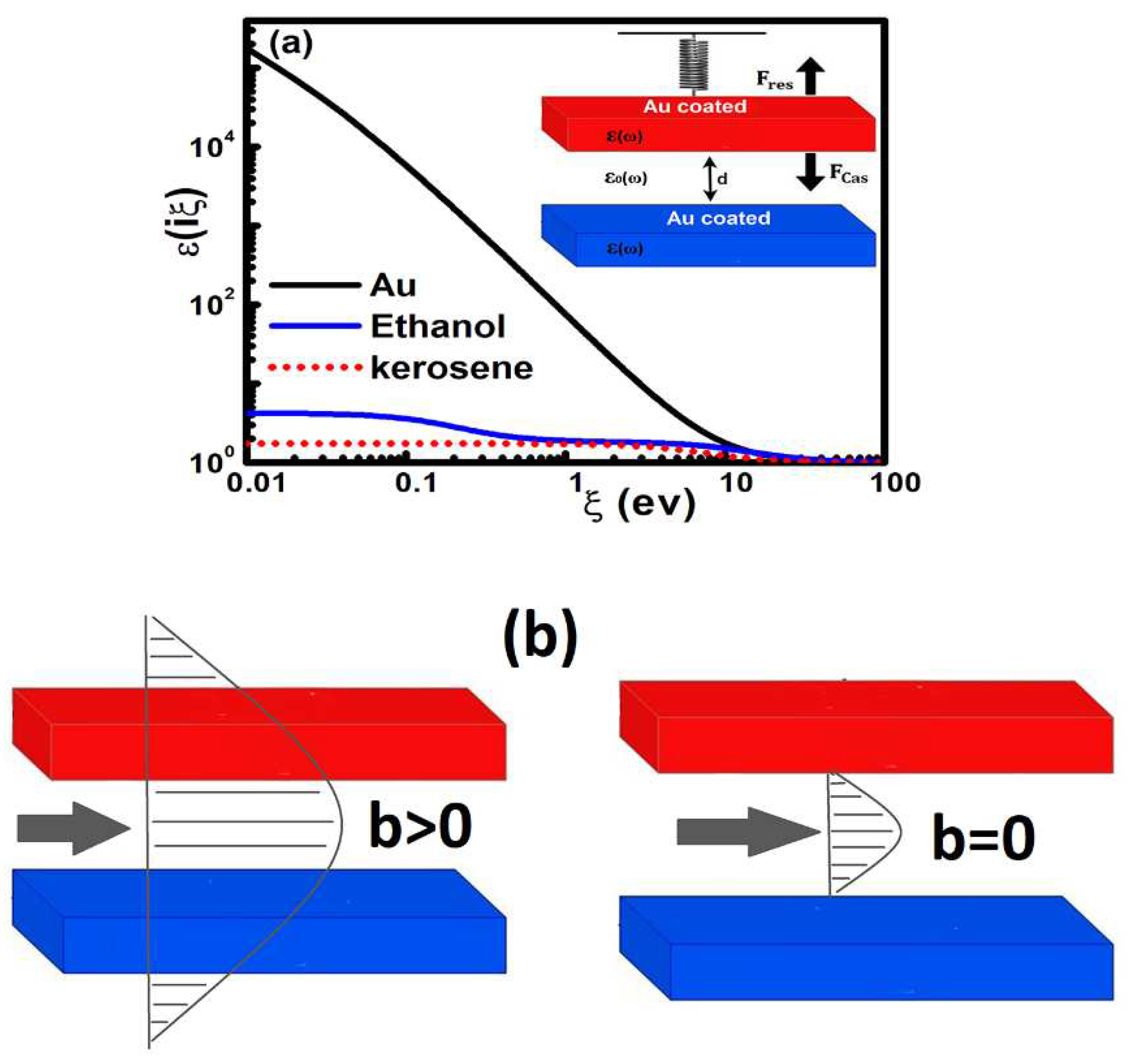
Figure 2.
Casimir reduction factor for different three-layer micro systems vs. separation between the plates. The fixed and moving components are assumed to be decorated Au with 100 nm thickness in order to be considered optically bulk. The intervening liquid layer is indicated.
Figure 2.
Casimir reduction factor for different three-layer micro systems vs. separation between the plates. The fixed and moving components are assumed to be decorated Au with 100 nm thickness in order to be considered optically bulk. The intervening liquid layer is indicated.
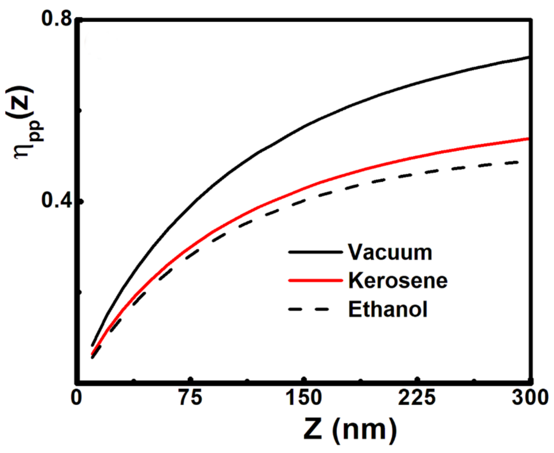
Figure 3.
Phase portraits for micro system which are coated with Au. We have considered Q=10000, 𝑧∗=0.95d, d=300 𝑛𝑚, and K∗=0.000465. (a) K >> K∗ where the value of K is indicated. (b) Influence of the damping term on the actuation dynamics of the Au-Au micro device with (K< K∗), and different values of the quality factor Q as it is indicated. The closed orbits indicate stable motion, while an open orbit is the sign of unstable motion leading to stiction. (c) Phase portraits for (K= K∗), and initial conditions inside and outside the homoclinic orbit. The stable center point and unstable saddle point are indicated.
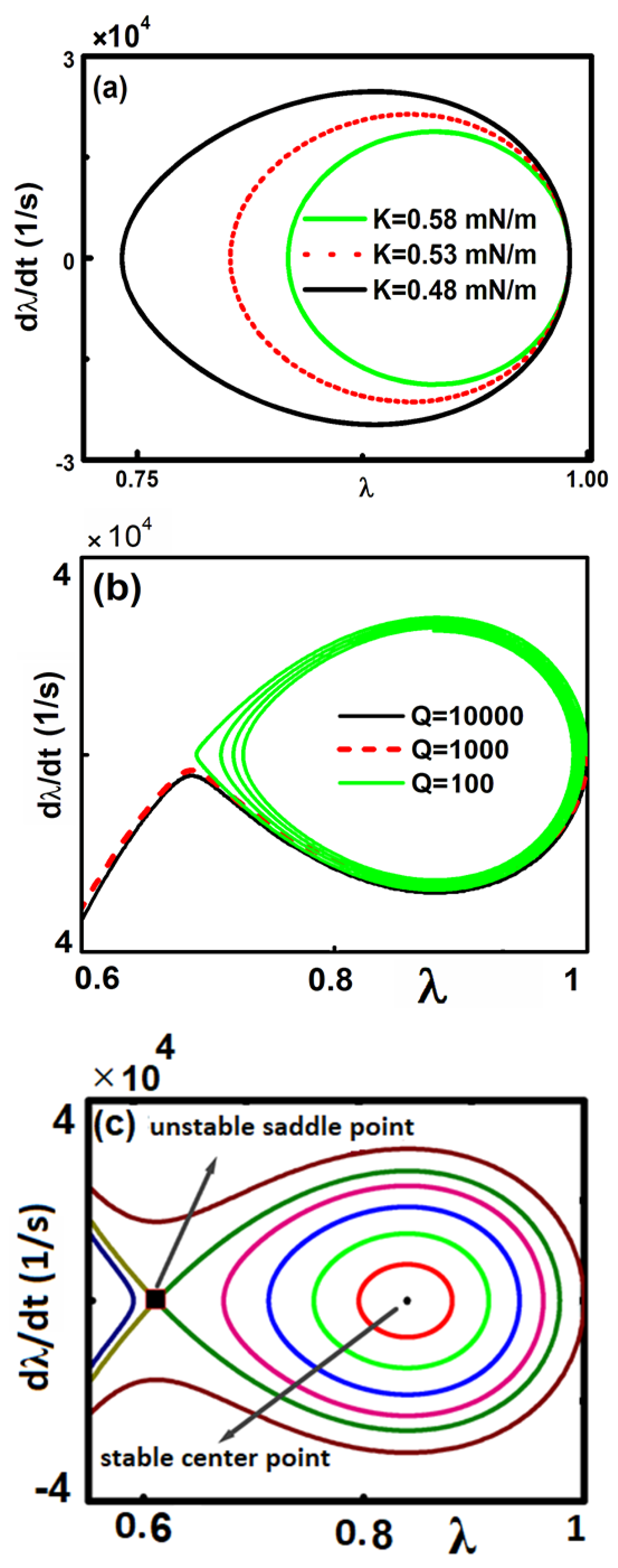
Figure 4.
Phase portraits for the three-layer Au microsystem with (a) ethanol (b) kerosene. We have considered 𝑧∗=0.5d, d=300 𝑛𝑚, and b=0. Phase space dissipative motion for various values of K (0.0005, 0.005, 0.05 N/m). Here we have =0.000635 N/m and =0.000675 N/m for the micro system containing ethanol and kerosene respectively.
Figure 5.
Phase portraits for the three-layer Au-Au microsystem with (a) ethanol (b) kerosene. We have considered 𝑧∗=0.5d, d=300 𝑛𝑚, and K >> K∗. The value of the slip length b is indicated. Here we have =0.000635 N/m and =0.000675 N/m for the micro system containing ethanol and kerosene respectively.
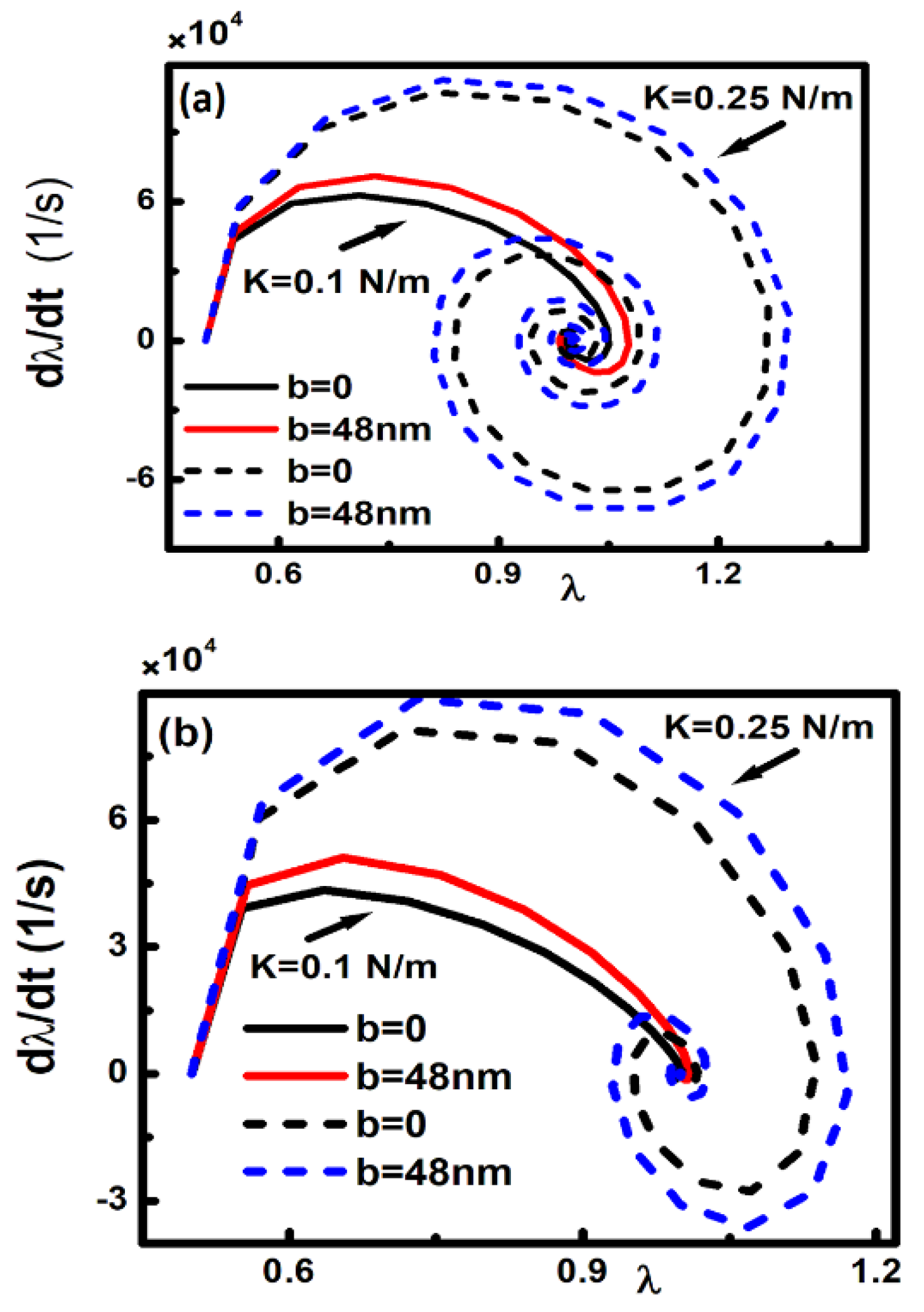
Figure 6.
Phase portraits for the both three-layer Au microsystem with ethanol and kerosene. We have considered 𝑧∗=0.5d and d=300 𝑛𝑚. (a) b=0 and the value of K is indicated. (b) the previous values of K are applied and the value of slip length b is indicated. Here we have =0.000635 N/m and =0.000675 N/m for the micro system containing ethanol and kerosene respectively.
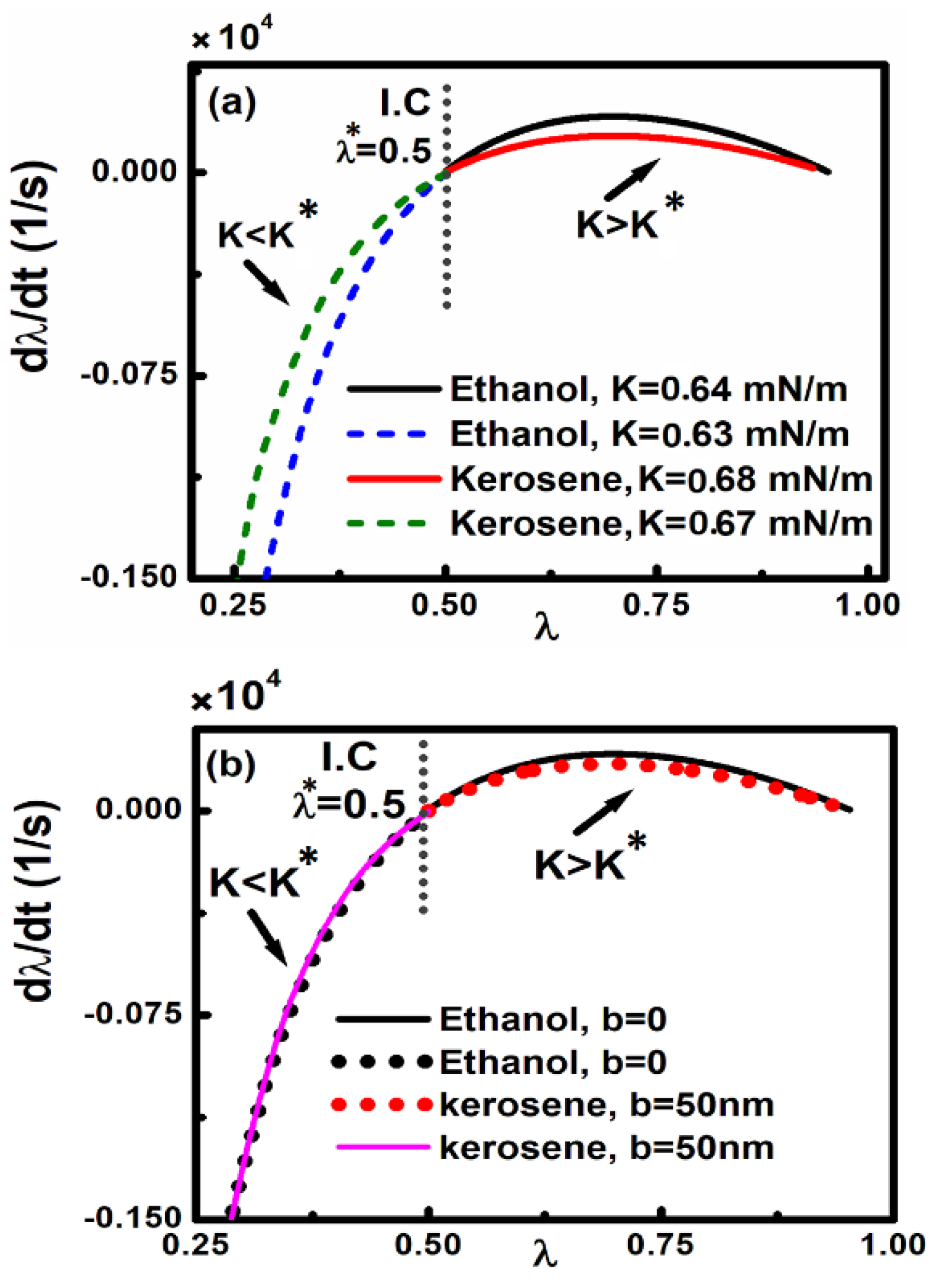
Figure 7.
Phase portraits for the driven microsystem with an external applied force F0cos(ωd t)) with ωd=0.5ω0. We have considered 𝑧∗=0.5d, d=300 𝑛𝑚, and K=0.05N/m. (a) Three layer Au micro systems (containing ethanol or kerosene) under the presence and absence of external driven periodic force without slip length (b=0). Three layer Au micro systems containing (b) ethanol and (c) kerosene under different applied driven periodic forces and varioud slip lengths as indicated.
Disclaimer/Publisher’s Note: The statements, opinions and data contained in all publications are solely those of the individual author(s) and contributor(s) and not of MDPI and/or the editor(s). MDPI and/or the editor(s) disclaim responsibility for any injury to people or property resulting from any ideas, methods, instructions or products referred to in the content. |
© 2023 by the authors. Licensee MDPI, Basel, Switzerland. This article is an open access article distributed under the terms and conditions of the Creative Commons Attribution (CC BY) license (http://creativecommons.org/licenses/by/4.0/).
Copyright: This open access article is published under a Creative Commons CC BY 4.0 license, which permit the free download, distribution, and reuse, provided that the author and preprint are cited in any reuse.


