1. Introduction
The escalating demand for fossil fuels has resulted in the depletion of underground oil reserves. If this consumption pattern persists, experts predict an imminent oil crisis. Moreover, the utilization of fossil fuels adversely impacts the environment, contributing to global warming and air pollution. Consequently, by mitigating fossil fuel consumption and reducing vehicle-related pollution, we can make significant strides in global pollution reduction and fuel conservation. Electric vehicles present a promising solution by enhancing efficiency, minimizing pollutants, and reducing reliance on fossil fuels. Hence, one effective approach to curbing fossil fuel consumption in transportation is the transition from internal combustion engine vehicles to electric vehicles (Bostanian et al., 2013). Furthermore, the market for all-wheel-drive and four-wheel-drive vehicles has witnessed substantial growth and transformation in recent years, with consumers demanding enhanced driving dynamics and vehicle stability. Consequently, the study of electric vehicle dynamics and control has placed significant emphasis on ensuring vehicle stability.
Various stability control systems have been developed to enhance the longitudinal and lateral dynamics of vehicles while simultaneously reducing fuel consumption. These systems are designed based on the precise control of tire forces, steering angle, and the distribution of torque among the wheels. Among these advanced systems, the torque distribution system demonstrates exceptional capabilities in allocating differential torque to the vehicle's wheels, tailored to specific driving maneuvers and road conditions. In contrast, certain limitations exist in other systems, such as the steering control system, which exhibits suboptimal performance in non-linear regions. Additionally, the electronic stability control system contributes to vehicle stability by distributing braking forces to the wheels, resulting in a reduction of the vehicle's speed. However, the torque distribution system effectively compensates for these limitations observed in alternative systems. As a result, it showcases exceptional performance in both linear and non-linear regions, ensuring vehicle stability without compromising speed.
To ensure effective torque distribution, precise control of external rotational torque is essential. Direct control of wheel rotational torque is recognized as an effective approach for achieving stability and controlling lateral dynamics. Various control methods have been investigated for regulating wheel rotational torque through torque distribution systems (Gan et al., 2013; Tavasoli & Naraghi, 2011; Braghin & Sabbioni, 2010; Rubin & Arogeti, 2015; Kasinathan et al., 2015; De Novellis et al., 2014a; Mashadi et al., 2011; Marino & Scalzi, 2008; Maroonian et al., 2013). Before delving into these methods, it is important to examine the inputs and outputs of different torque distribution strategies. While many researchers have focused on wheel rotational speed as a control variable (Gan et al., 2013; Tavasoli & Naraghi, 2011), others have explored lateral slip angle (Braghin & Sabbioni, 2010) or a combination of both variables (Rubin & Arogeti, 2015). Some researchers have designed controllers with the objective of minimizing both longitudinal and lateral wheel forces (Kasinathan et al., 2015). Furthermore, certain studies have incorporated physical limitations of the propulsion system, such as the maximum torque output, to enhance controller performance (De Novellis et al., 2014a). Conversely, the outputs of the torque distribution system typically involve wheel rotational torque around the vehicle's center of gravity. The disparity in longitudinal forces (traction force) between the right and left wheels gives rise to the generation of wheel rotational torque (Mashadi et al., 2011; Marino & Scalzi, 2008; Maroonian et al., 2013).
Numerous control methods have been developed for torque distribution systems, and several of these methods are examined in the following discussion. The PID controller, a classical and widely-used control structure, stands out as one of the simplest in terms of implementation. (De Novellis et al., 2014b) conducted a study focusing on designing external torque control, where they explored two distinct approaches. These approaches include pre-feedforward PID control and robust pre-feedforward PID control, both of which were investigated in their research.
The sliding mode control, renowned for its nonlinear and robust characteristics, has garnered significant attention among researchers. Rieveley and Minaker (2007) have devised a control law for computing the external torque employing the sliding mode control approach. To facilitate this, they employed a linear two-degree-of-freedom model.
Mousaei and Peng (2023) have enhanced the stability and maneuverability of an electric vehicle by employing a fuzzy logic control approach and an electronic stability control system. In a separate study, Mousaei and Allahyari (2023) examined three controllers, namely PID, adaptive fuzzy, and adaptive robust fuzzy controllers, and identified the controller with the lowest mean square error as the most suitable option.
Predictive control methods have been employed by researchers as well. In this approach, the controller anticipates the future behavior of the system and applies optimal control inputs to minimize the error of performance variables. Nahidi et al. (2017) have utilized the Model Predictive Control (MPC) technique to determine the necessary forces and rotational torque for minimizing the discrepancy between the actual and desired rotational speed, lateral speed, and slip angle.
On the contrary, the optimal position controller holds a significant position within the torque distribution system. Kasinathan et al. (2015) have developed an optimal torque vectoring control for vehicle applications, considering real-time constraints. Their control strategy aims to optimize torque distribution in real-time to enhance vehicle performance. Li et al. (2015) have further extended the optimal torque distribution control strategy for four-independent wheel drive electric vehicles. Their approach focuses on minimizing tracking errors, reducing actuator control energy, and minimizing tire workload.
In the study conducted by Chen et al. (2013), a novel direct yaw moment controller is proposed for in-wheel motor electric vehicles. This controller aims to enhance the vehicle's stability and maneuverability by controlling the yaw moment directly. The proposed controller utilizes a sliding mode control approach and considers the dynamics of in-wheel motor electric vehicles. The effectiveness of the controller is evaluated through simulations and experimental tests.
Wong et al. (2016) propose an integrated torque vectoring and power management framework for electric vehicles. The framework incorporates an algorithm that optimizes the wheel torque distribution while considering the constraints of the actuators. By utilizing various optimization functions, the controller determines the optimal torque distribution among the wheels, considering factors such as vehicle dynamics, stability, and energy efficiency. The proposed framework aims to enhance the overall performance and efficiency of electric vehicles.
In most of the aforementioned studies, the primary objective of the controller is to minimize the tracking error of the desired parameter for vehicle stability. In this research, a novel approach is introduced to stabilize the motion of a four-wheel electric vehicle while considering an allowable tracking error for rotational speed parameters, along with energy consumption control. Given the significance of battery consumption in electric vehicles and the limited torque production of electric motors for vehicle stabilization, employing expensive optimization control schemes can help reduce battery consumption and enable the electric motors to operate within their permissible range. Therefore, by adjusting the weight coefficients, an attempt is made to strike a balance between energy and control objectives for the allowable tracking error while ensuring that the electric motors operate within their power range. Based on this concept, the proposed control system is designed in two layers. In the first layer, the required external stabilizing torque for ensuring lateral dynamic stability is minimized. After distributing forces between the wheels using an optimal algorithm and applying an inverse tire force model, the desired slips are calculated. These values are then fed as inputs to the lower layer controller to obtain the necessary control inputs for generating the driving forces. The controllers are designed using an optimal nonlinear predictive control method, where analytical approaches are employed instead of numerical methods to find optimal solutions. The control of the driving forces in the electric vehicle is engineered to ensure stability during various driving maneuvers, particularly during acceleration, while considering energy consumption.
This article is structured into the following sections. Following the introduction,
Section 2 introduces the combined model of the vehicle simulator and the control system.
Section 3 presents the torque distribution system and its configuration in the context of this study. In
Section 4, the optimal controller is discussed, employing a predictive design approach, along with its performance and stability analysis.
Section 5 presents simulation results obtained using MATLAB software. Finally, the last section offers a comprehensive conclusion summarizing the work conducted.
2. The vehicle simulator model
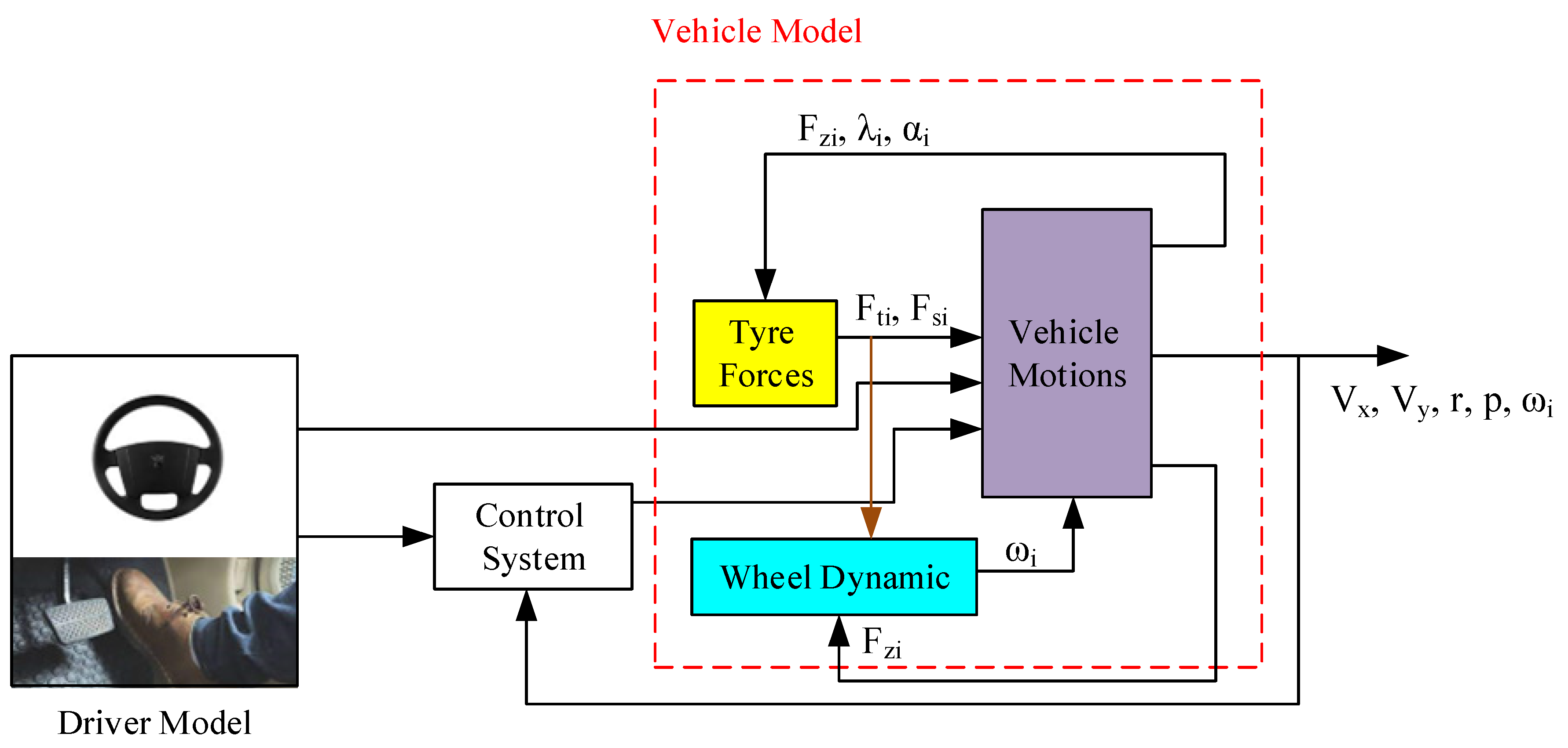
The combined control system presented in this study is simulated using a nonlinear eight-degree-of-freedom vehicle model. The overall structure of the simulator model is illustrated in
Figure 1. In this model, the longitudinal velocity (v
x), lateral velocity (v
y), yaw rate (r), and roll speed (p) are considered as the degrees of freedom, along with the angular velocity of the four wheels (i=1,...,4) (ω
i). The forces acting on the wheels, namely F
si (longitudinal force), F
ti (lateral force), and F
zi (vertical force), are included, as well as the longitudinal slip (λ
i) and slip angle (α
i) of each tire. The model can be divided into three main parts, representing the vehicle's motion, tire forces, and wheel dynamics, respectively.
Smith and Starkey (1995) investigate the effects of model complexity on the performance of automated vehicle steering controllers. The study focuses on model development, validation, and comparison to assess the impact of different modeling approaches on the performance of steering controllers. The research explores various aspects such as model complexity, accuracy, and validation techniques to understand their influence on controller performance. The findings contribute to improving the understanding of how model complexity affects the design and implementation of automated vehicle steering controllers.
3. Torque distribution system
The torque distribution system is an advanced technology that allocates torque to each wheel based on its specific requirements, enabling independent torque transfer. This system significantly enhances vehicle maneuverability and traction capabilities. Consequently, the torque distribution system serves as a stability system for vehicles, enhancing their dynamic behavior in accordance with varying road conditions. Importantly, this system achieves improved vehicle behavior without compromising longitudinal performance. In other words, it ensures vehicle stability without sacrificing speed, akin to the electronic stability control system (Braghin & Sabbioni, 2010).
In the study conducted by (Yuan and Wang (2012)), a torque distribution strategy for a front- and rear-wheel-driven electric vehicle is proposed. The research focuses on optimizing the torque distribution system to improve the vehicle's performance and stability. The study considers the unique characteristics of a front- and rear-wheel-drive configuration and develops a strategy to effectively distribute torque among the wheels. By optimizing the torque distribution, the researchers aim to enhance the vehicle's traction, handling, and overall driving experience.
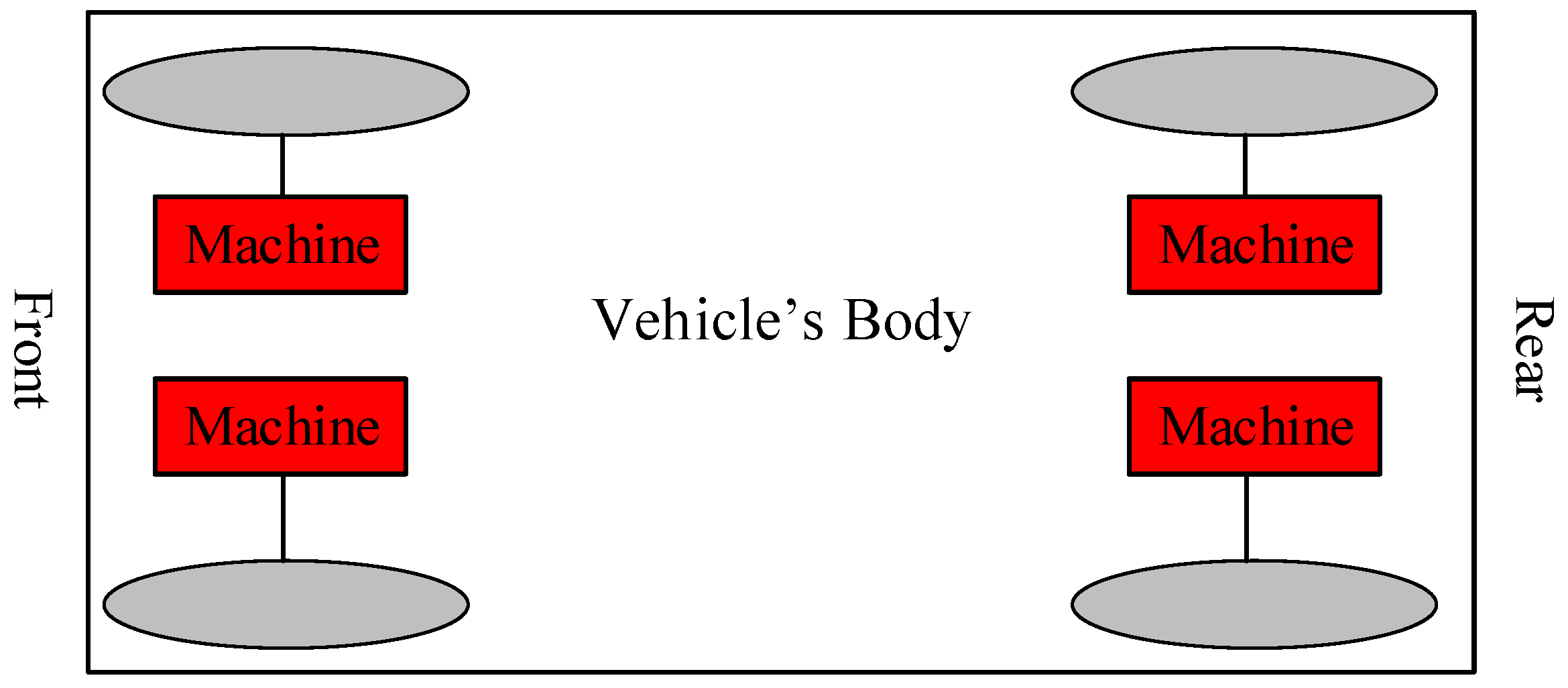
Figure 2.
The layout of an electric vehicle with four separate electric motors.
Figure 2.
The layout of an electric vehicle with four separate electric motors.
4. Designing the control system
4.1. Overall control system diagram
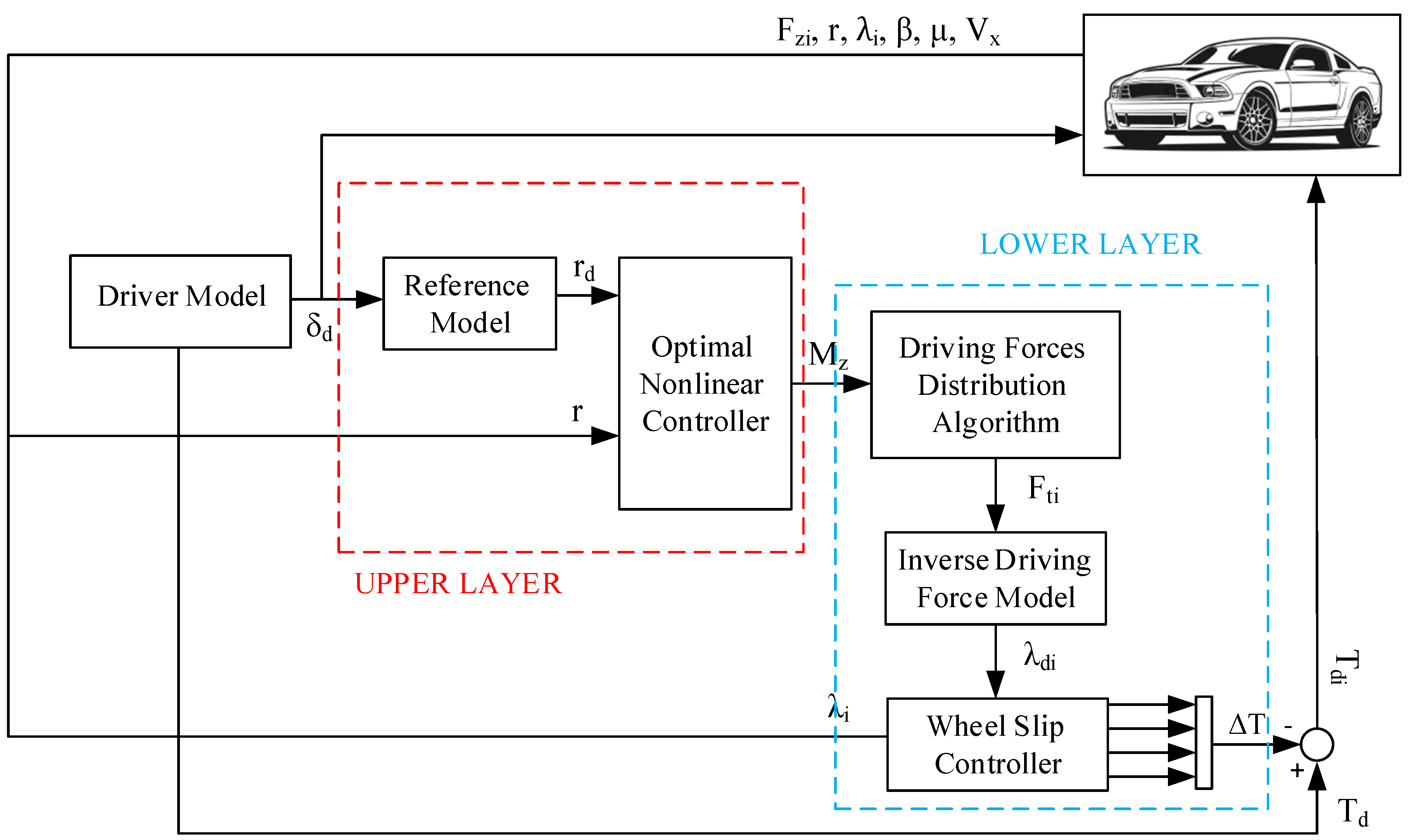
The control system's overall architecture is depicted in
Figure 3, consisting of two hierarchical layers: the wheel rotation control system and the longitudinal slip control system. The first layer is responsible for determining an optimal wheel rotation torque, considering physical limitations, to ensure lateral motion stability. This torque is then translated into differential forces between the wheels, and the inverse tire model is employed to derive the corresponding longitudinal slips. These slip values are subsequently fed into the second layer control system for tracking purposes. The inverse model aims to establish the desired longitudinal slip based on the prescribed longitudinal forces. Employing a nonlinear two-degree-of-freedom model, the wheel rotation control system is designed using an optimal predictive approach. In the second layer, each electric motor adjusts its control input to accurately track the actual slip and maintain stability for the electric vehicle model. The longitudinal slip control system, focusing solely on longitudinal dynamics, relies on a five-degree-of-freedom vehicle model and an optimal control methodology. It adjusts its control input based on the reference longitudinal slip to precisely follow the actual slip of the corresponding wheel.
4.2. Longitudinal Slip Control based on a Five-Degree-of-Freedom Vehicle Model
In this section, we develop an optimal predictive controller to generate the longitudinal slip using a five-degree-of-freedom vehicle model. The model incorporates the longitudinal vehicle speed and the angular velocities of the four wheels as its degrees of freedom. Consequently, the governing equation for the longitudinal dynamics can be expressed as follows:
Where in the above equation, m represents the total mass of the vehicle, F
t is the traction force, and v
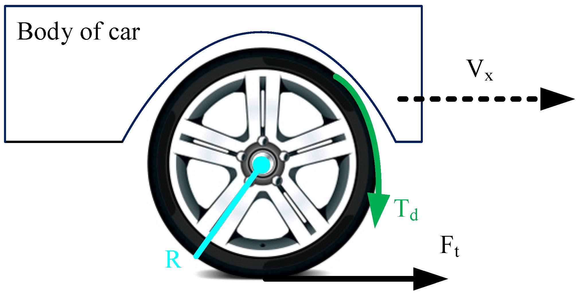
x is the longitudinal acceleration of the vehicle. Note that in equation (1), the indices correspond to the vehicle wheels, where fL represents the front left wheel, rL represents the rear left wheel, fR represents the front right wheel, and rR represents the rear right wheel. This assumption holds true for subsequent equations as well. Additionally, according to
Figure 4, the rotational dynamics for each wheel are modeled as equation (2):
That, T represents the wheel torque, Iω is the moment of inertia of the wheel, and is the wheel angular acceleration.
The longitudinal slip of the vehicle is defined according to equation (3) for two modes: braking and a lower definition for acceleration mode.
In equation (3), ω represents the angular wheel velocity, R is the wheel radius, and vx is the longitudinal velocity.
By taking the derivative of the acceleration section, equation (4) can be obtained as follows:
By substituting
and
from equations (1) and (2) into equation (4), equation (5) can be obtained as follows:
In this article, the saturation property of tires is considered, and the Dugoff model is used (De Novellis et al., 2014b). The equations for longitudinal and lateral forces in this model are given by equations (6) to (9).
In the given context, Ft and Fs represent the longitudinal and lateral tire forces respectively, Fz stands for the vertical load, Cλ and Cα represent the longitudinal and lateral tire stiffness respectively, lateral tire slip is represented by α, and εr is the tire adhesion reduction factor.
Taking longitudinal velocity and longitudinal slip as state variables, torque as the control input, and longitudinal slip as the output, equations (1) and (5) can be written in state-space form as follows:
That [x
fL x
rL x
fR x
rR]=[λ
fL λ
rL λ
fR λ
rR] are slip values of the four wheels (fL, rL, fR, rR), and x
1=v
x represent the longitudinal velocity. The cost function of the system is considered according to equation (13).
Considering that the control input appears in the first derivative of the output, the relative degree of the system is equal to one. Therefore, to approximate the term x
i(t+h
l), it is sufficient to expand it up to the first derivative according to equation (14) (Mirzaeinejad and Mirzaei, 2014).
To obtain the optimal control law, the necessary optimality condition according to the following equation is applied:
By substituting equation (14) into equation (31) and applying the optimality condition and rearranging the torque equation according to equation (16), we obtain the following result.
In the above equation, eλi=λi-λdi. Additionally, λdi represents the desired and reference longitudinal slip, which are calculated for each tire at each moment based on the desired longitudinal forces. For vehicle stability, the longitudinal forces of each wheel are obtained from the force distribution algorithm based on the required external rotational torque. The calculation of the external torque in the first layer of the proposed control system, along with the corresponding longitudinal force distribution and extraction of the desired slips for each wheel, will be presented in Section (3.4). In fact, by knowing the reference and desired slips of each wheel, which will be discussed in the next section, the torque distribution system of each wheel is designed using equation (16).
4.2.1. Evaluation of the Longitudinal Stability Control Law
This section discusses the evaluation of the closed-loop control law system (16). To this end, by substituting equation (16) into equation (11) of the closed-loop system dynamics, the tracking error is obtained as follows:
In the above error equation, f
i represents the deviation from the nominal value
, which is caused by uncertainties in the vehicle model. Now, let's assume that the uncertainties are bounded and have an upper limit, which can be expressed as follows:
Where ξ
i is a positive number.
In order to evaluate the performance of the control law (16) and analyze the error in the presence of uncertainties, the Lyapunov function is used according to the following equation:
By substituting equation (17) into the time derivative of the Lyapunov function, equation (20) is calculated as follows:
By considering the upper bound of the uncertainty from equation (18), it can be concluded:
Now, we use the well-known inequality derived from the second law of thermodynamics for the second term inside the parentheses in equation (21):
In which a, b, and
are real and positive numbers. By applying equation (22) to equation (21), equation (23) is obtained as follows:
By solving the differential equation (32), the following conclusion can be drawn:
It is observed that in the above equation, the error approaches the range of over time, and the system stability is guaranteed according to Lyapunov. However, this error can be controlled by adjusting the free parameter hl. In the designed controller, achieving asymptotic stability along with convergence of the error towards zero is not possible because it requires selecting h1=0. On the other hand, since hl is present in the denominator of the control law, selecting a value of zero is not feasible. Therefore, if achieving zero error is necessary, it is suggested to use integral feedback, as mentioned in reference (Mirzaeinejad and Mirzaei, 2010).
4.3. Control of Four-Wheel Vehicle Model
4.3.1. Reference Model for Vehicle Wheel Rate
In this article, the reference model used is one that mimics the behavior of a real vehicle. This model is chosen in such a way that, based on the steering input, road conditions, and vehicle speed, it exhibits complete stability and demonstrates suitable behavior. The non-linear and saturation properties of tire forces during extreme maneuvers are the most significant factors contributing to vehicle instability and can result in inadequate vehicle behavior. Therefore, a second-order linear model is employed as the reference model.
4.3.2. Wheel Torque Controller
In this section, the development of the control law is based on a nonlinear two-degree-of-freedom model of a four-wheel vehicle that neglects the roll degree of freedom. It should be noted that the roll degree of freedom is considered in the vehicle's simulator model. The equations for lateral velocity and lateral angular velocity of the vehicle are obtained according to equations (25) and (26).
In these equations, v
y and r represent the system states, while M
z is the control input and r is the output. By rewriting these equations in state-space form, equations (27), (28), and (29) can be obtained as follows:
The cost function of this system is considered according to equation (30).
In the above equation, w1>0 and w2>=0 are the weighting coefficients for the rotational velocity variable and the control input, respectively. Additionally, h
2 represents a known positive constant interval, which is the prediction horizon. Since the control input appears in the first derivative of the output, the relative degree of the system is one. As a result, to approximate the term r(t+h
2), a Taylor series expansion can be obtained according to equation (31).
Similar to equation (31), to consider the effects of the reference rotation, the term r
d(t+h
2) is also expanded up to the first derivative according to equation (32).
By substituting equations (12) and (32) into equation (30) and applying the optimality condition in the cost function, the control law for torque can be obtained as equation (33).
In the above control law, if w2/w1=0, no weight coefficient is considered for the control input, meaning that the control input is inexpensive. Additionally, if w2/w1=ꝏ, in this case, Mz=0, which is known as the "bang-bang" controller. In this article, by determining appropriate weight coefficients and compromising between them, efforts have been made to achieve the allowable tracking error of the rotational speed while ensuring the stability of the vehicle and minimizing the control energy as much as possible. This approach ensures that the electric motors operate within their power range and optimizes the usage of the electric vehicle's battery.
4.3.3. Force Distribution Algorithm
The algorithm for force distribution is implemented in the following manner; Initially, the vehicle operates under specific initial conditions with an initial torque applied to each wheel. If the generated rotational torque matches the required value for vehicle stability, the vehicle continues its motion while maintaining stability with the initial conditions. However, if the generated torque deviates from the required value, the forces and torques on both sides are adjusted to align with the desired torque (Mirzaeinejad and Mirzaei, 2014).
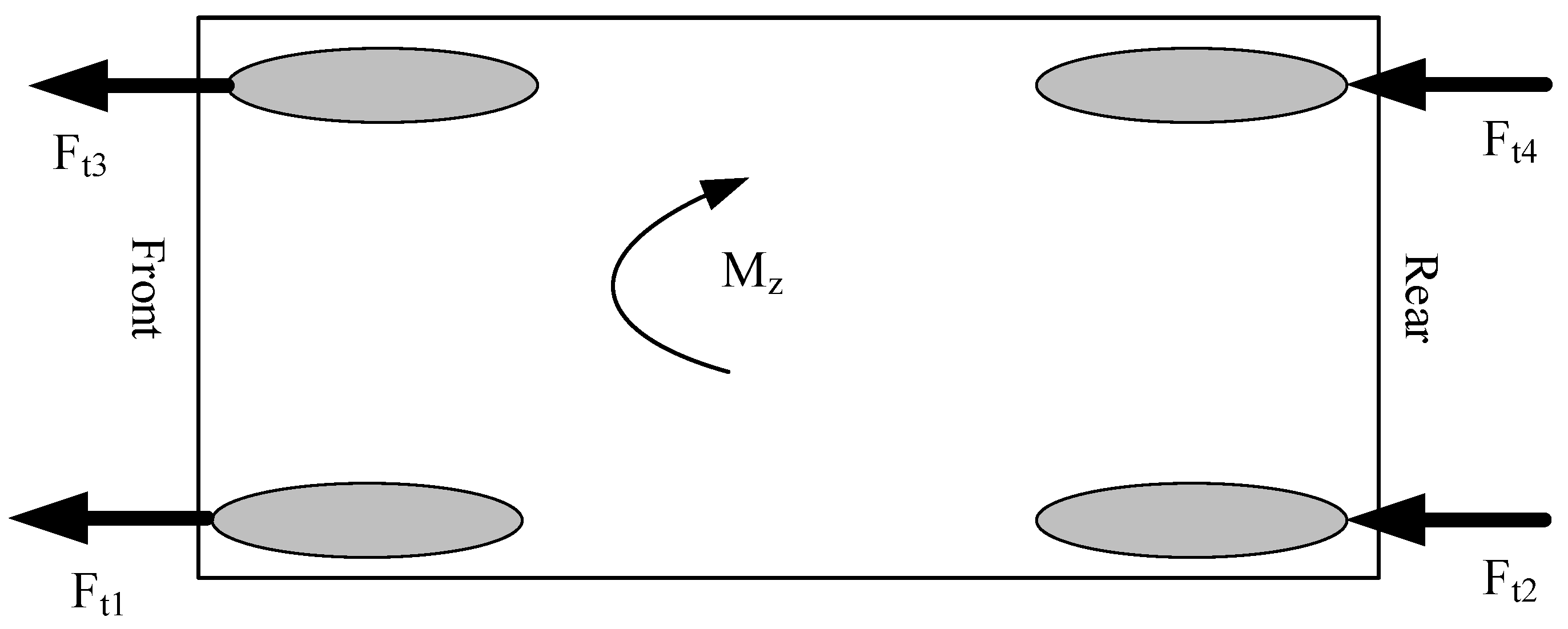
Figure 5 illustrates the input to this algorithm, which is the control rotational torque, and the outputs are the traction forces of the tires.
In
Figure 5, indices are used to denote the tire forces. According to this convention, the front-left tire, rear-left tire, front-right tire, and rear-right tire are represented by indices 3, 2, 1, and 4, respectively. The rotational torque caused by the tire traction at each moment is calculated according to equation (34), considering the indices of the tire forces as depicted in
Figure 5.
Mzt = Mz: In this case, the vehicle exhibits stable behavior, and no corrective external torque is required. Thus, the torque distribution system, with an equal distribution of tire forces resulting from the initial wheel torques, provides maximum acceleration for the vehicle, allowing it to continue along its initial path.
Mzt > Mz: In this case, considering the necessary sign of the required external torque, the torque distribution system becomes active to generate the desired torque. With an appropriate distribution of traction forces resulting from the output torque of each independent motor connected to the wheels, the system ensures the stability of the vehicle. For example, in the case of an understeering vehicle rotating to the right, the active torque distribution system initially reduces the traction force of the inner wheels and increases the traction force of the outer wheels to create the corrective torque. It is worth mentioning that during acceleration, the load transfer occurs from the front axle to the rear axle, so the rear wheels have a greater traction capacity. Therefore, to improve the acceleration performance, the traction force is initially increased for the rear wheels and decreased for the front wheels.
Mzt < Mz: This case is similar to the second case, with the difference that the positions of the tire forces are swapped. With the knowledge of the traction forces for each wheel, torque distribution is performed among the wheels in a way that the calculated forces from the distribution algorithm are achieved. To do this, the longitudinal slips corresponding to each force are calculated using the inverse model of tire forces. The calculated longitudinal slips are then used as desired values for the longitudinal slip controller (16) to calculate the motor torques for tracking them.
The torque distribution between the wheels is performed in such a way that the calculated forces from the distribution algorithm are obtained. For this purpose, the corresponding longitudinal slip for each force is calculated using the inverse model of tire forces. The calculated longitudinal slips are provided as desired values to the longitudinal slip controller, enabling the calculation of the wheel motor torques by tracking them.
5. Simulation Results
In this section, to evaluate the performance of the proposed control system, necessary simulations have been conducted and analyzed on the 8th-order nonlinear vehicle model. The parameters related to the vehicle and the physical constants used in the simulations are listed in
Table 1.
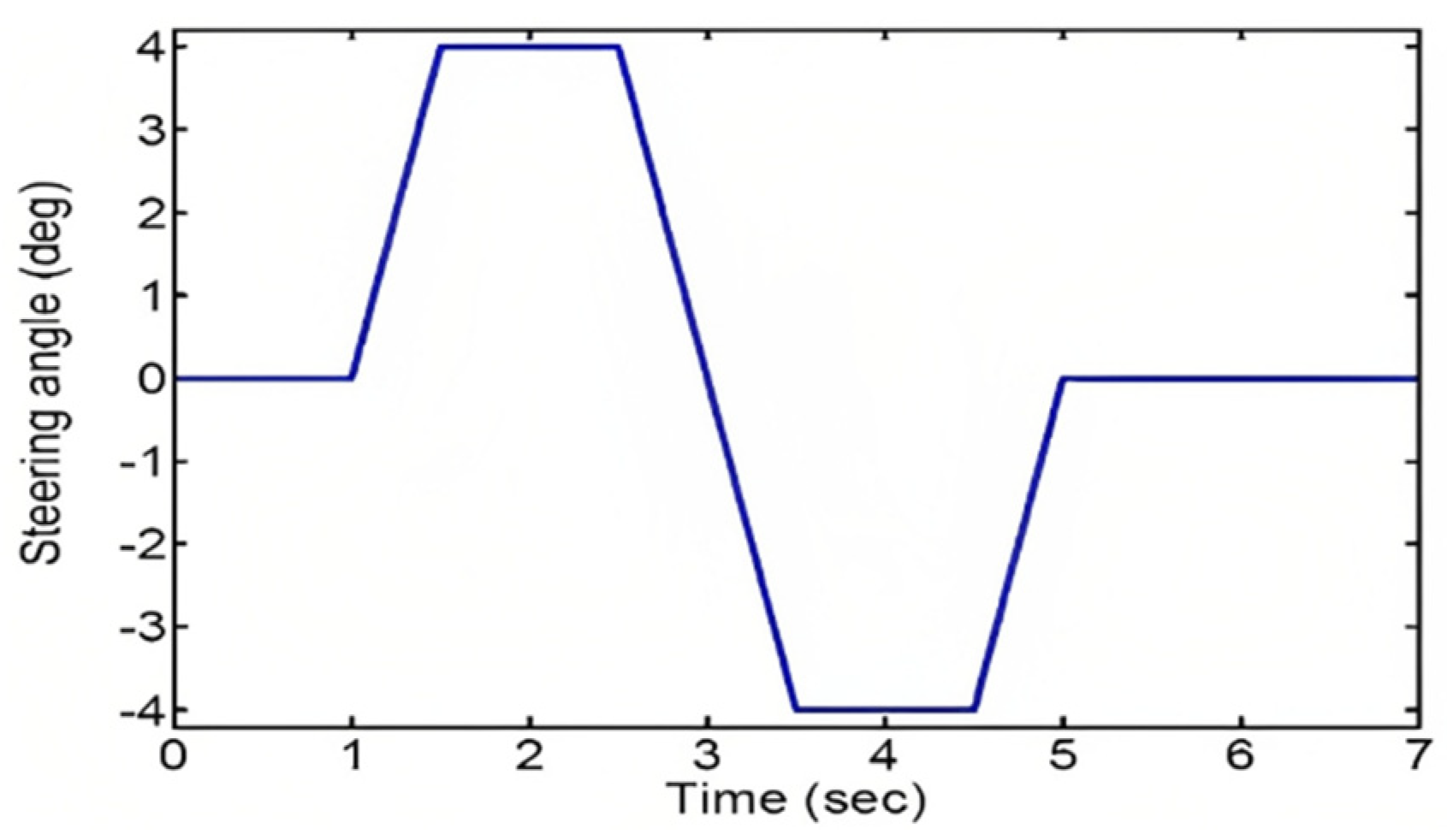
The maneuver used in this scenario is a lane change maneuver with an initial speed of 60 kilometers per hour on a level road surface with a coefficient of friction of 0.8 (μ=0.8) and the initial lateral acceleration of 0.3, as indicated by the steering angle in
Figure 6. In this situation, the control system assists the driver in maintaining lateral stability of the vehicle without reducing speed, allowing the vehicle to remain on the intended path.
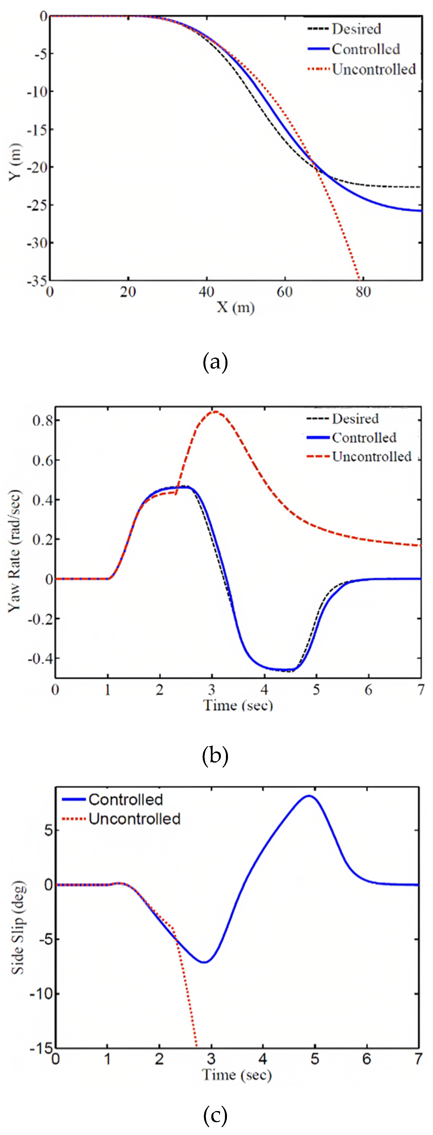
Simulation results for this case are presented in Figures (7) to (10). In
Figure 7, the responses are compared in controlled and uncontrolled conditions. The results show that in the uncontrolled condition, due to the presence of destabilizing forces and wheel slip, the vehicle moves towards instability. However, in the controlled condition, by generating the desired torque and longitudinal slip, the responses follow the desired values. The time responses of the vehicle rotational speed and lateral slip angle are shown in Figure 7. As seen in
Figure 7b, the vehicle rotational speed in the controlled condition tracks the reference value (r
d). Also, according to
Figure 7c, the lateral slip angle in the uncontrolled condition continues to increase, leading to vehicle instability, while in the controlled condition, it reaches a stable state.
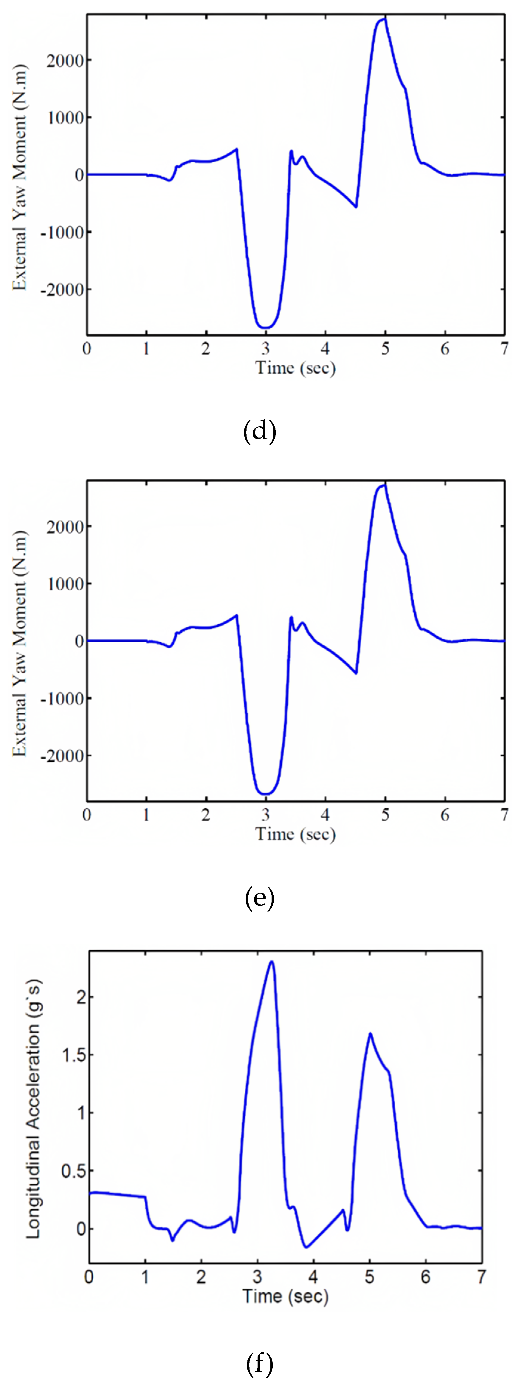
Figure 7d shows the vehicle speed, where in the uncontrolled condition, due to wheel slip, it suddenly increases, causing the vehicle to deviate from the path. However, in the controlled condition, stability is maintained without speed reduction, which is one of the features of the torque distribution system that ensures stability without speed reduction, unlike other systems such as electronic stability control.
Figure 7e shows the input torque for the control system, which is calculated in the first layer for precise vehicle stabilization using the predictive controller.
Figure 7f illustrates the longitudinal acceleration of the vehicle during the maneuver. Since the vehicle moves with an initial acceleration of 0.3, this acceleration is evident in the first second of motion. In
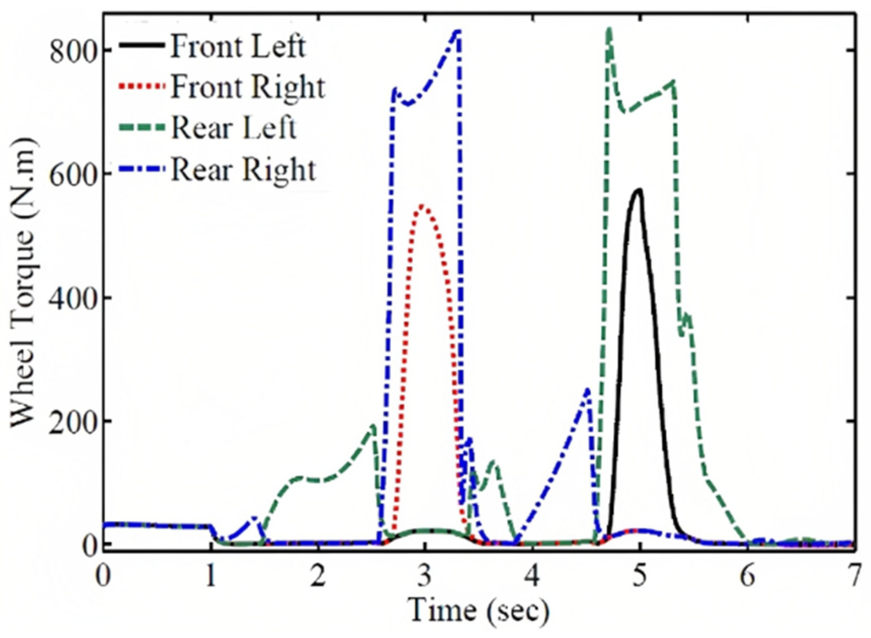
Figure 8, the distributed wheel torques for external rotational torque are shown. Since the vehicle is in motion with initial acceleration, the initial torque is distributed to each wheel as shown in the figure. According to the figure, the required torque for each wheel exceeds the power of the electric motors.
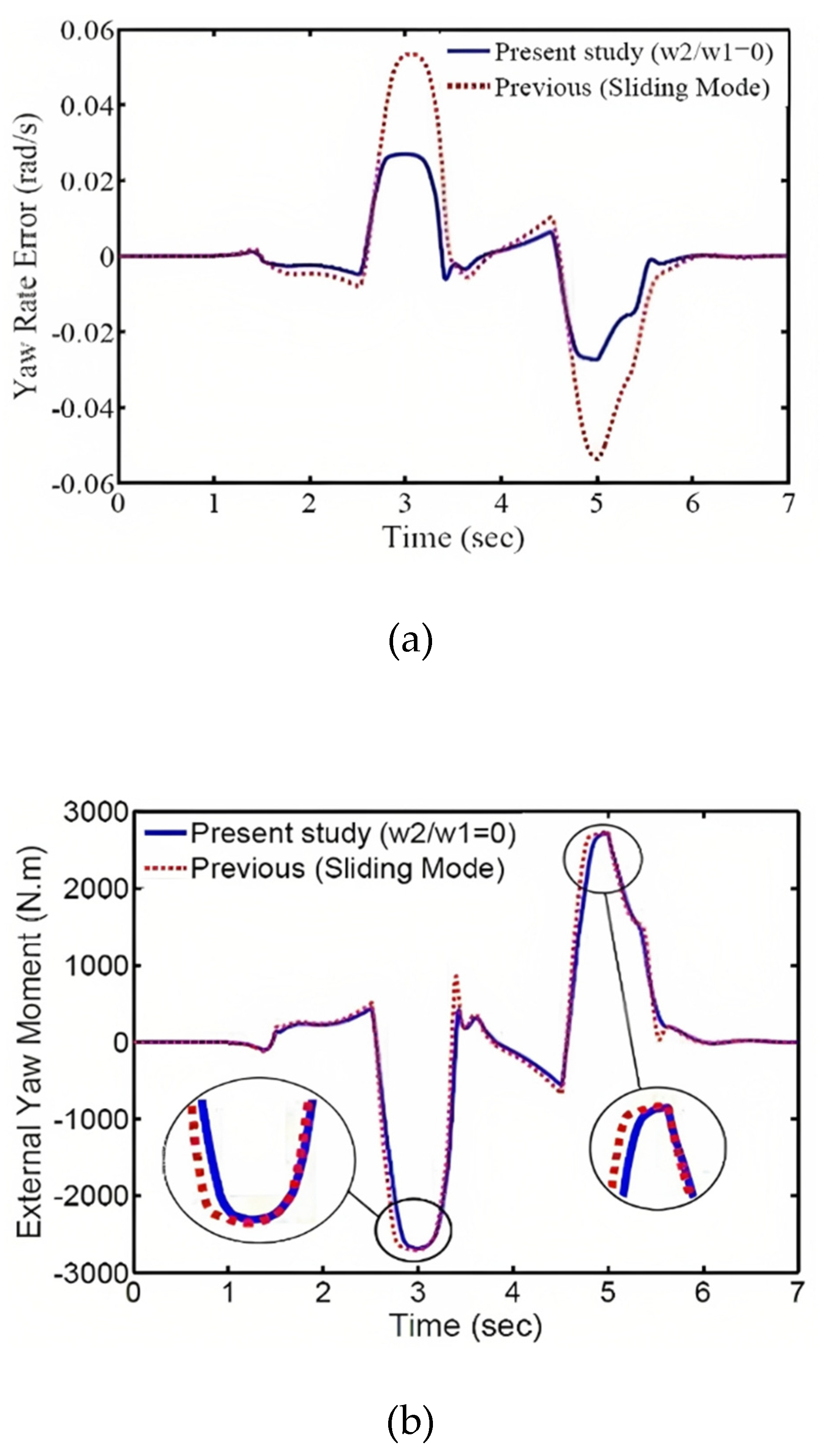
As mentioned earlier, many researchers have used different vehicle models for controller design investigations. In various references, the sliding mode method has been employed to calculate the external torque (Cho et al., 2008; De Novellis et al., 2014b). This method only has the capability to minimize the wheel rotational speed error, which corresponds to the special control state of w
2/w
1=0 in this article. In
Figure 9, the dynamic responses obtained from the sliding mode method are compared with the responses of the proposed special control state in this article. According to Figures 9a and 9b, the proposed special control state shows relatively better performance in terms of error and energy compared to the sliding mode method.
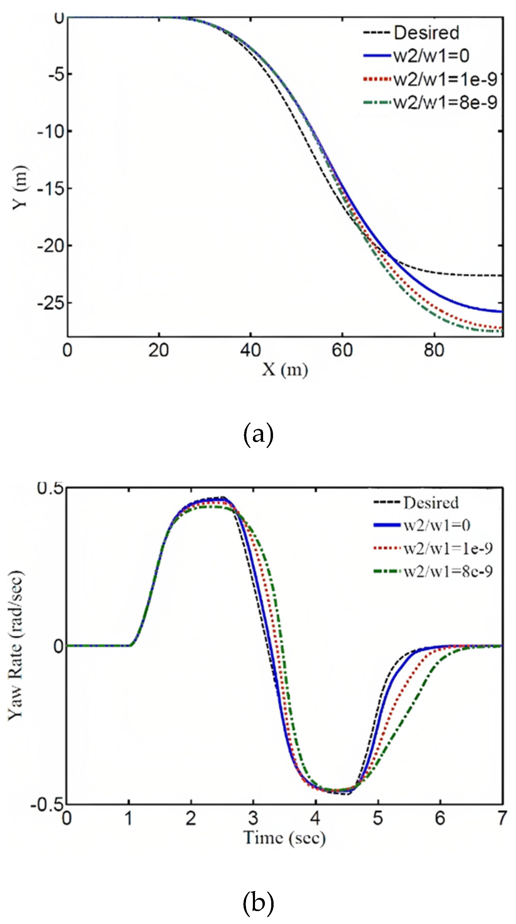
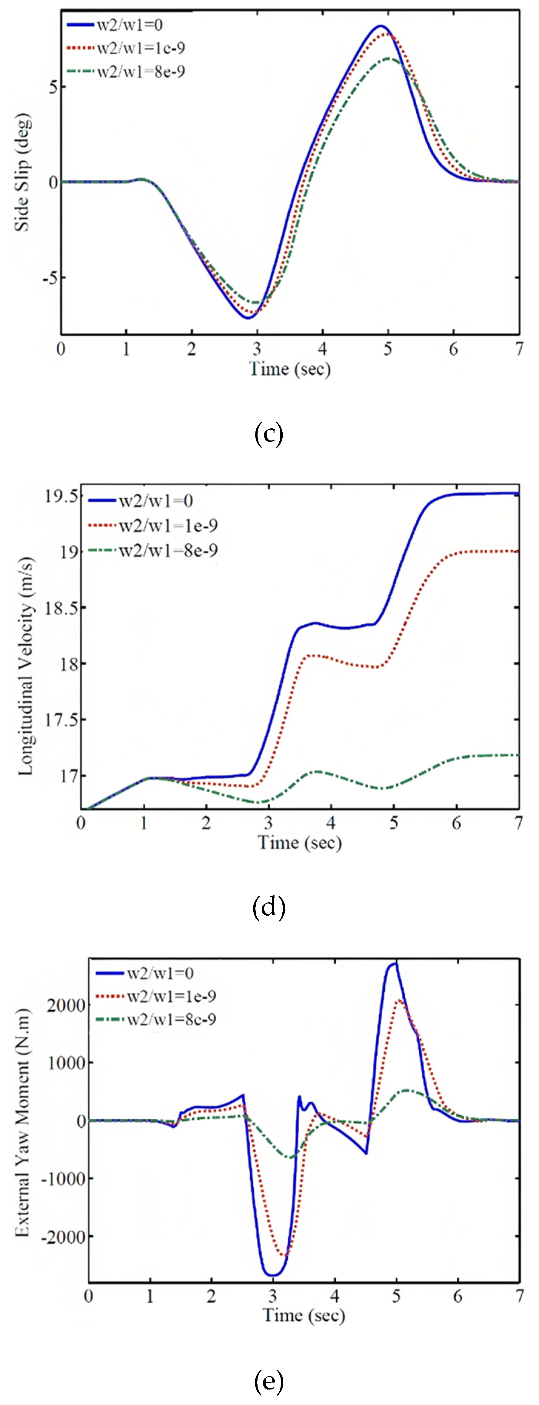
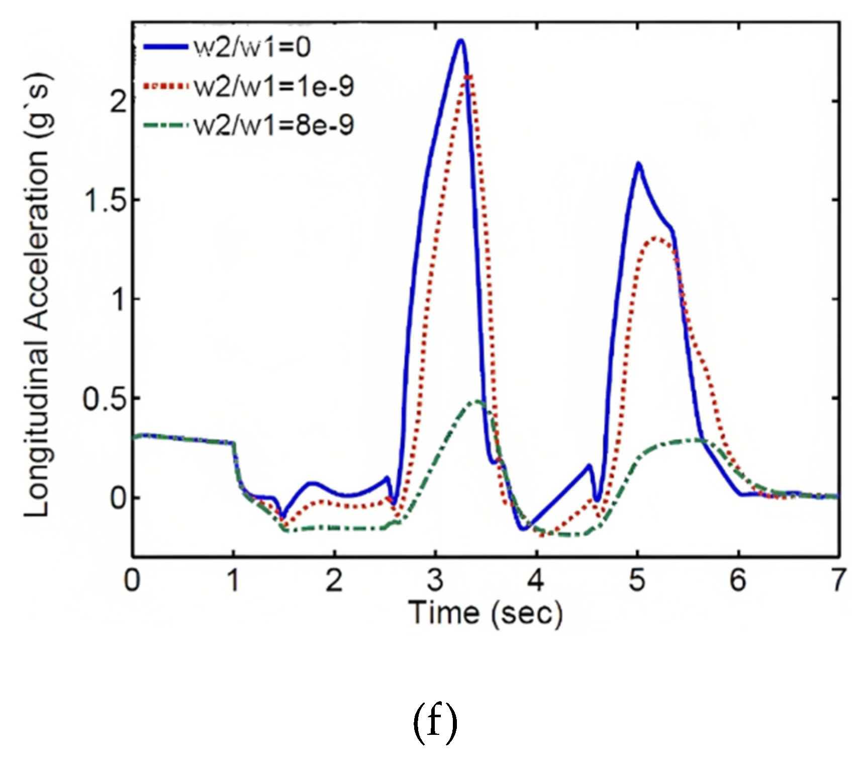
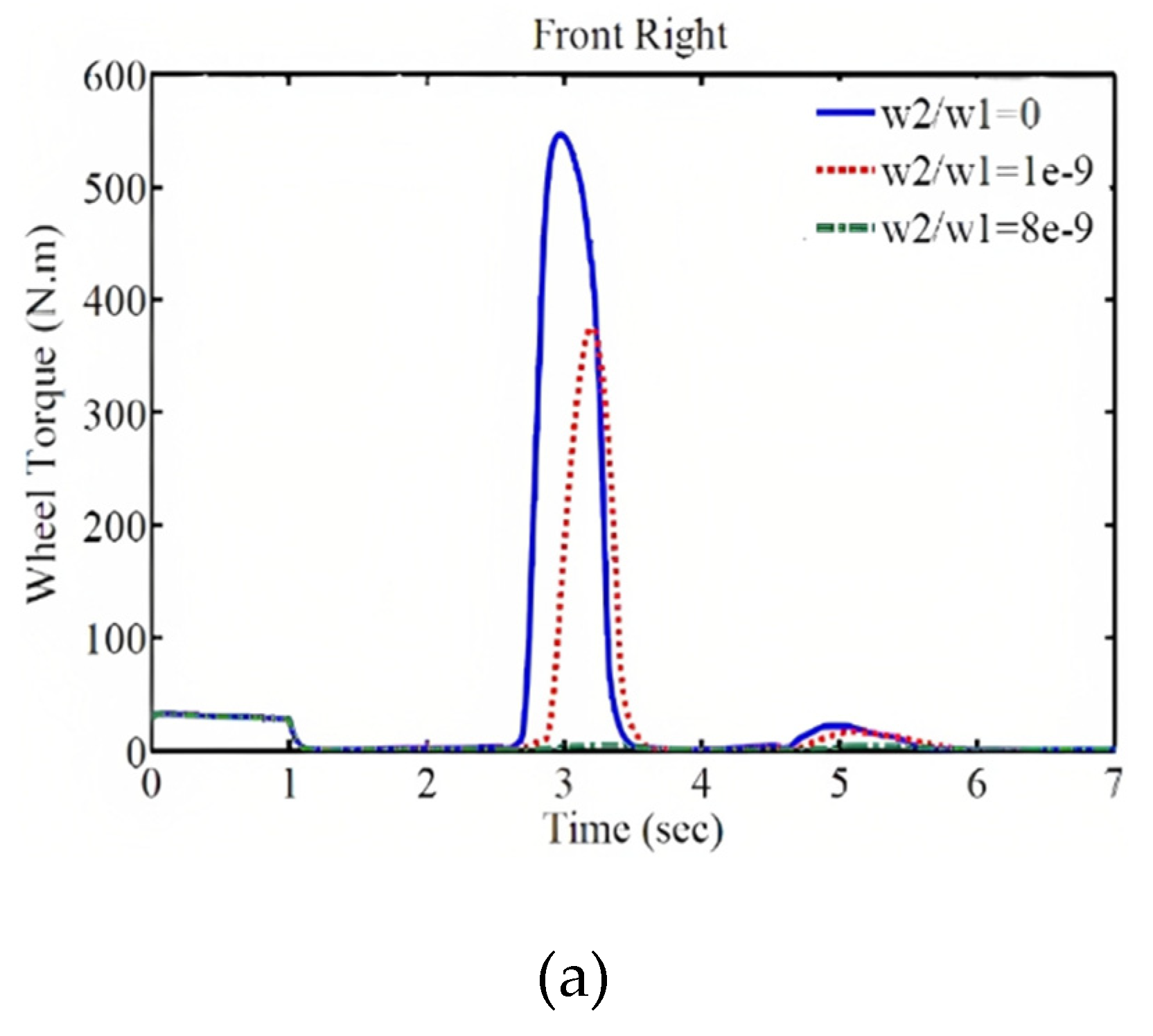
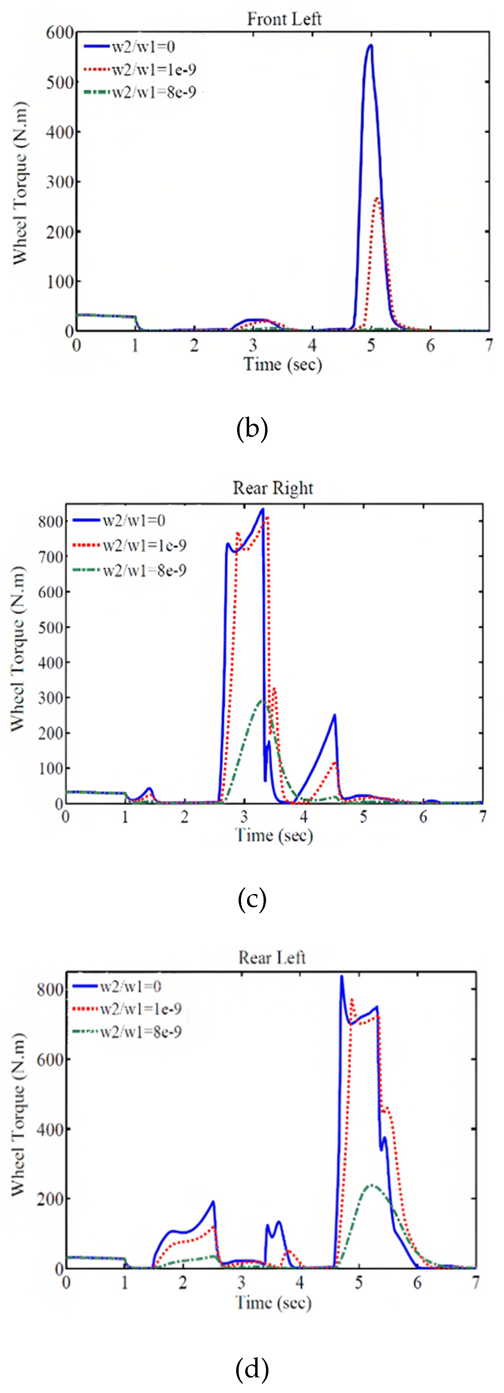
In this case, the total torque of the electric motors decreases significantly, as shown in the subsequent section where the weighting coefficients and their results are presented. Figure 10 demonstrates the effect of the weighting coefficient on the performance of the control system. The comparison of the vehicle trajectory, wheel speed response, lateral slip angle, longitudinal speed, longitudinal acceleration, and the required external wheel torque for different weighting coefficient values is shown in this figure. As observed, with an increase in the weighting coefficient, the magnitude of the external wheel torque decreases. As a result, the trajectory, wheel speed, lateral slip angle, and their deviation from the desired values increase, but these deviations and tracking errors remain within an acceptable range. Furthermore, increasing the weighting coefficient reduces the vehicle's speed at a specified time, resulting in a shorter traveled distance. On the other hand, decreasing the external wheel torque reduces the energy consumption and enhances the control of the system.
Figure 10.
Vehicle Responses with Different Weighting Coefficients: (a) Trajectory, (b) Wheel Speed, (c) Lateral Slip Angle, (d) Longitudinal Speed, (e) External Wheel Torque, and (f) Longitudinal Acceleration.
Figure 10.
Vehicle Responses with Different Weighting Coefficients: (a) Trajectory, (b) Wheel Speed, (c) Lateral Slip Angle, (d) Longitudinal Speed, (e) External Wheel Torque, and (f) Longitudinal Acceleration.
As a result, by compromising between speed and control energy, favorable conditions can be created. As mentioned earlier, the power of the electric motors is limited in generating wheel torque. Therefore, by adjusting the weighting coefficients, the required torque for each wheel should be within the allowable range. Additionally, considering the permissible tracking error, the energy consumption of the electric motors should be minimized to optimize the use of the electric vehicle's battery and cover a greater distance with a single battery charge. According to
Figure 11, with an increase in the weighting coefficient, the torque applied by the motors to each wheel decreases and falls within the power range of the electric motors.
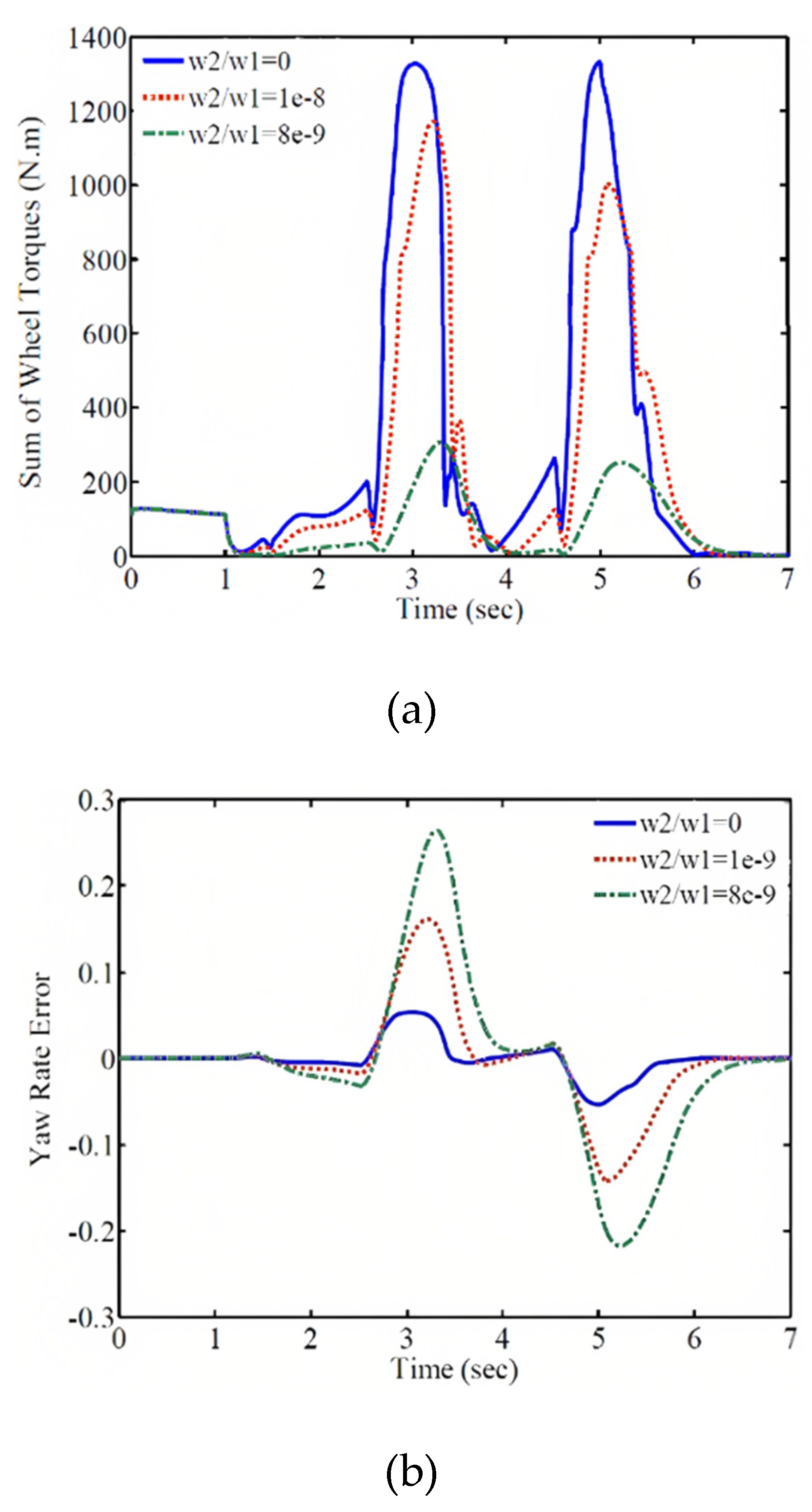
Also, this adjustment of weighting coefficients leads to energy management and reduction in energy consumption, as demonstrated in
Table 2 and Figures 12a and 12b. As observed, with an increase in the control input weighting coefficient, the total torque required for the stability of the vehicle's four wheels decreases, while the wheel rotational speed error increases. Furthermore, by calculating the total torque of the four wheels in the sliding mode control method, which is equal to 2188.2 Nm, and comparing it with the specific case of the optimally designed controller in this study (w
2/w
1=0), it is noted that in the optimal control mode, this value is approximately 6% lower than the sliding mode method. This is one of the advantages of the optimally designed controller. It should be mentioned that with this trade-off between energy and control objective, the electric motors operate within their permissible range, and the energy consumption is reduced by considering the permissible tracking error for the control objective, allowing for a significant reduction in the total torques of the electric motors. This leads to optimal utilization of the electric vehicle's battery and minimizes its usage as much as possible. By adjusting the weighting coefficients, a compromise is made between the wheel forces and the control objective, and the wheel drive forces fall within their permissible range. Furthermore, considering that energy is expensive from a control perspective in electric vehicles, the forces can be set lower than their permissible range, provided that the permissible tracking error for the control objective is satisfied, in order to minimize energy consumption.
Table 2.
The sum of wheel torques and wheel speed errors for different weight coefficients.
Table 2.
The sum of wheel torques and wheel speed errors for different weight coefficients.
| The control input weighting coefficients |
The total torque of the four wheels (N.m) |
The rotational speed error |
| w2/w1=0 |
2054.4 |
0.0778 |
| w2/w1=e-9 |
1670.2 |
0.2234 |
| w2/w1=8e-9 |
582.4 |
0.4011 |
Figure 12.
Total wheel torque and rotational speed error for different weight coefficients. (a) Total wheel torque (b) Rotational speed error.
Figure 12.
Total wheel torque and rotational speed error for different weight coefficients. (a) Total wheel torque (b) Rotational speed error.
6. Conclusion
Considering the importance of stable rotation and energy efficiency in electric vehicles, this article proposes a combined control system based on optimization using the optimal predictive control method. In this approach, the control input is determined in such a way that the predicted tracking error for future time steps is minimized. By adjusting the weight coefficients and optimizing the wheel torque, a compromise between energy consumption and improved vehicle stability is achieved. As a result, the controller can ensure stability while reducing energy consumption. Since electric motors have limited torque during vehicle operation and energy is expensive, the weight coefficients are adjusted to generate optimal wheel torque, allowing the motors to operate within their power range and minimize energy consumption.
Appendix 1
For designing a controller using a fuzzy logic approach, a fuzzy logic controller at the single-level, which is a function of rotational speed error, is defined:
In such a way that its derivative is also defined as follows:
Continuing, by substituting equation (28) into equation (36), it is possible to express the derivative of the fuzzy logic surface equation as a function of the control input.
By setting equation (37) equal to zero, the equivalent control input (M
zeq) is obtained. On the other hand, in order to satisfy the sliding conditions without considering uncertainty, the discontinuous term -ksgn(S
s) is added to the equivalent control input equation, resulting in the following equation:
In the above equation, the coefficient 'k' is obtained using equation (39).
The above inequality is known as the sliding condition, where 'ξ' is a positive constant. It is necessary to clarify that in order to eliminate the chattering effect caused by the control input, the saturation function () is replaced as a continuous approximation of sgn(Ss).
References
- Bostanian, M., Barakati, S. M., Najjari, B., & Kalhori, D. M. (2013). A Genetic-Fuzzy Control Strategy for Parallel Hybrid Electric Vehicle. International Journal of Automotive Engineering, 3(3), 482-495. [CrossRef]
- Gan, Y. H., Xiong, L., Feng, Y., & Martinez, F. (2013). A Torque Vectoring Control System for Maneuverability Improvement of 4WD EV. In Applied Mechanics and Materials (Vol. 347-350, pp. 899-903). [CrossRef]
- Tavasoli, A., & Naraghi, M. (2011). Comparison of static and dynamic control allocation techniques for integrated vehicle control. IFAC Proceedings, 44(1), 7180-7186. [CrossRef]
- Braghin, F., & Sabbioni, E. (2010). Development of a control strategy for improving vehicle safety in a hybrid vehicle with four independently driven in-wheel motors. In International Symposium on Advanced Vehicle Control.
- Rubin, D., & Arogeti, S. A. (2015). Vehicle yaw stability control using active limited-slip differential via model predictive control methods. Vehicle System Dynamics, 53(9), 1315-1330. [CrossRef]
- Kasinathan, D., Kasaiezadeh, A., Wong, A., Khajepour, A., Chen, S. K., & Litkouhi, B. (2015). An Optimal Torque Vectoring Control for Vehicle Applications via Real-Time Constraints. IEEE Transactions on Vehicular Technology, 65(6), 4368-4378. [CrossRef]
- De Novellis, L., Sorniotti, A., & Gruber, P. (2014). Wheel torque distribution criteria for electric vehicles with torque vectoring differentials. IEEE Transactions on Vehicular Technology, 63(4), 1593-1602. [CrossRef]
- Mashadi, B., Mostaani, S., & Majidi, M. (2011). Vehicle stability enhancement by using an active differential. Proceedings of the Institution of Mechanical Engineers, Part I: Journal of Systems and Control Engineering, 225(8), 1098-1114. [CrossRef]
- Marino, R., & Scalzi, S. (2008). Integrated active front steering and semiactive rear differential control in rear-wheel-drive vehicles. In Proceedings of the 17th IEEE IFAC World Congress. [CrossRef]
- Maroonian, A., Tamura, T., & Fuchs, R. (2013). Modeling and Simulation for the Dynamic Analysis of an Electronically Controlled Torque Coupling. In Advances Automotive Control (Vol. 46, No. 21, pp. 464-469). [CrossRef]
- De Novellis, L., Sorniotti, A., Gruber, P., & Pennycott, A. (2014). Comparison of feedback control techniques for torque-vectoring control of fully electric vehicles. IEEE Transactions on Vehicular Technology, 63(8), 3612-3623. [CrossRef]
- Rieveley, R.J. and Minaker, B. (2007). Variable Torque Distribution Yaw Moment Control for Hybrid Powertrains. [CrossRef]
- Mousaei, A., & Peng, H. (2023). A New Control Method for the Steadiness of Electric Vehicles with 2-Motor in Rear and Front Wheels. Research Square. [CrossRef]
- Mousaei, A., & Allahyari, H. (2023). An Improved Dynamic Programming Energy Management System for Parallel Hybrid Electric Vehicles According to Battery Model. [CrossRef]
- Nahidi, A., Kasaeizadeh, A., Khosravani, S., Khajepour, A., & Litkhouhi, B. (2017). Modular integrated longitudinal and lateral vehicle stability control for electric vehicles. Mechatronics, 44, 60-70. [CrossRef]
- Li, B., Goodarzi, A., Khajepour, A., Chen, S.-k., & Litkouhi, B. (2015). An optimal torque distribution control strategy for four-independent wheel drive electric vehicles. Vehicle System Dynamics, 53(8), 118. [CrossRef]
- Chen, Y., Hedrick, J., & Guo, K. (2013). A novel direct yaw moment controller for in-wheel motor electric vehicles. Vehicle System Dynamics, 51(6), 925-942. [CrossRef]
- Wong, A., Kasinathan, D., Khajepour, A., & Chen, S.K. (2016). Integrated torque vectoring and power management framework for electric vehicles. Control Engineering Practice, 48, 22-36. [CrossRef]
- Smith, D. E., & Starkey, J. M. (1995). Effects of Model Complexity on the Performance of Automated Vehicle Steering Controllers; Model Development, Validation and Comparison. Vehicle System Dynamics, 24(2), 163-181. [CrossRef]
- Yuan, X., & Wang, J. (2012). Torque distribution strategy for a front- and rear-wheel-driven electric vehicle. IEEE Transactions on Vehicular Technology, 61(7), 3365-3374. [CrossRef]
- Mirzaeinejad, H., & Mirzaei, M. (2014). Optimization of nonlinear control strategy for anti-lock braking system with improvement of vehicle directional stability on splitmu roads. Transportation Research Part C, 46, 1-15. [CrossRef]
- Mirzaeinejad, H., & Mirzaei, M. (2010). A novel method for nonlinear control of wheel slip in anti-lock braking systems. Control Engineering Practice, 18(8), 918-926. [CrossRef]
- Cho, W., Yoon, J., Kim, J., Hur, J., & Yi, K. (2008). An investigation into unified chassis control scheme for optimized vehicle stability and maneuverability. Vehicle System Dynamics, 46, 87-105. [CrossRef]
|
Disclaimer/Publisher’s Note: The statements, opinions and data contained in all publications are solely those of the individual author(s) and contributor(s) and not of MDPI and/or the editor(s). MDPI and/or the editor(s) disclaim responsibility for any injury to people or property resulting from any ideas, methods, instructions or products referred to in the content. |
© 2023 by the authors. Licensee MDPI, Basel, Switzerland. This article is an open access article distributed under the terms and conditions of the Creative Commons Attribution (CC BY) license (http://creativecommons.org/licenses/by/4.0/).
