
Submitted:
28 August 2023
Posted:
29 August 2023
You are already at the latest version
Abstract
The first Network Arch Bridge (NAB) was opened to traffic 60 years ago and since then the idea spread around the world. It is a type of a tied arch bridge that combines the benefits of tied arch bridges and trusses in a single system, thus it has a very good stiffness even in the case of extremely slender structures. In a Network Arch the hangers are inclined and some of them intersect each other at least twice. The core of a NAB is the hanger arrangement that minimizes the bending moment in the arch to very small values, leading thus to compression in the arch. This paper reviews the Network Arch idea devised by prof. Tveit and extended by researchers and engineers worldwide. A comprehensive review of the literature about the Network Arch is provided and the situation of NABs around the world from the standpoint of location, span, structural system used for the cross-section, bridge type (road, railway, combined or pedestrian) and opening year is discussed.
Keywords:
Network Arch Bridge
; arch bridge
; hanger arrangement
; arch curvature
; curvature variation
; tied arch bridge
1. Introduction
As professor Per Tveit states in [1,2], while working on his master thesis in 1955, he came with the idea of an arch bridge with inclined hangers that crossed each other at least twice. He gave the new structure the name “network arch” and it has been the centerpiece of his research for years to come. Professor Tveit first structure is the Network Arch at Steinkjer in Norway, completed in 1963, with a carriageway of 6m and a span of 80m. In the 67 years that have passed since he had the idea, Network Arches extended through the globe, being now present in more than 30 countries. At [2] is a map constantly updated with locations of newly built Network Arch Bridges (referred to as NAB through the paper). As the authors found during the research conducted for the current state of the art, many network arch structures are not yet included in the map at [2].
One could consider that NABs are like Nielsen bridges, but some differences should be considered, making the difference between NABs and Nielsen structures. O.F. Nielsen [4] designed arch bridges with inclined hangers with or without an inter-section point along the tie or the arch. The sloping of the hangers in his proposal reduces the bending in the chord [5] because a load on the left side of the span activates the hangers sloping to the right, equalizing the load on the arch. Nielsen did not build arch bridges with hangers crossing each other, but in a patent from 1926 he showed such a bridge, with some of the hangers crossing once. Figure 1.a shows a Nielsen bridge built in 1933 in France, and Figure 1.b a drawing from Nielsen’s patent from 1926. NABs as stated through the definition, are arch bridges with sloping hangers that cross each other at least twice. Network Arches have a very good stiffness, a better distribution of the bending moments along the arches compared to arches with vertical hangers and can be designed as the world’s most slender arch bridges. To this point, as stated in [5] and [6] the world’s most slender NAB is Brandanger Bridge in Norway. The first NABs proposed and studied followed Tveit recommendations [1] to have the arch made of steel and the tie made of concrete, with the arch part of a circle with a constant curvature. Later, researchers started to investigate the behavior of NABs with the arch having different curvatures, or the arch part of a parabola and the tie a composite section or the arch made using different construction materials such as concrete of timber.
The first part of the paper will explain Per Tveit’s vision on the optimal NAB and the research conducted following his recommendations. The second chapter will detail other structural types proposed for NABs and the research conducted. Where research was based on built structures, those structures will be presented. As in today’s world, machine learning algorithms are expanding, several research was published, investigated the optimization of NABs using different types of algorithms. Research conducted with the purpose of optimizing NABs will be detailed next, accompanied by other recent studies on the structural behavior of NABs.
2. Per Tveit vision and conception of the Network Arch Bridge
Professor Tweit’s recommendations in designing the Network Arch [1] are oriented in the direction of the best efficiency to cost ratio. This chapter is based on Per Tveit vision on the optimal shape of Network Arches [2].
The arch should be part of a circle [1] and the curvature of the arch near the supports should be part of a circle with a reduced radius, Figure 2 [5], so that increased cross sections are shorter. It should be mentioned here that up until the paper published in 2019 [5], the recommendation given was for the curvature near the supports to have a radius of about 80% of the radius of the curvature of the arch [1].
The cross-section for the arch should be a universal column or a similar American wide flange beam [1,2] due to the slim look universal columns give to the Network Arch, less welding and simpler details. In the design of the network arches by Teich and Wendelin in 2001 for their graduation thesis [7], the cross-section chosen was a universal column UC 356x406x551 made of steel with a yield stress of 430N/mm2, presented in Figure 3 [1]. In the same figure a comparison with two box sections with the same area is presented. The comparison shows that the box cross-section in the middle is 64% wider than the universal column and it has a moment of inertia 2.7 times higher. The box section at the right, even though visually has a similar effect to the universal column, Per Tveit considers it to be unpractical compared to the universal column; UC requires smaller amount of welding, simpler details, and smaller dimensions.
According to [2], when the arches are less than 15 m apart, the stie should be a concrete slab with edge beams spanning between the arches. The two edge beams are to be on the same plane as the plane of the arches. This solution ensures a good distribution of the concentrated loads, while the solution with crossbeams concentrates the forces. The tensile force in the tie will be taken by prestressing cables located in the edge beams. The proposed cross-section for the tie is presented in Figure 4 [2]. Transverse prestressing might be necessary for distances between the arches larger than 10m.
For a slab made of concrete C40/50, depending on the span of the slab in the transverse di-rection, the necessary thickness was computed by Teich and Wendelin [7], Figure 5. They studied a two-lane road bridge with a span of 135m, the lower chord similar to Figure 4 and the arch cross-section, the universal column in Figure 2. The necessary slab thickness is valid for the case mentioned, where the lower chords are made of pre-stressed concrete wide beams.
Under the guidance of prof. Tveit and prof. Wolfgang Graβe, in 2002, Uve Steinmann [8] finished designing a double track railway NAB, using the Eurocodes. The span of the railway bridge was 100m. Steinmann thesis focused only in designing the bridge, but it was then used as a benchmark for the thesis of Brunn and Schanack [9] where a lot of effort was placed on the optimization of the hanger arrangement. In [9] the authors devised 850 different hanger arrangements that were compared to search for the minimum internal forces and about 100 bridges were calculated varying the geometry of the bridge in terms of span, arch rise, number of hangers an arch curvature. One hanger arrangement proposed in [9] was based on the proposal of Tveit [1] and Teich and Wendelin [7], where it was suggested for the hangers to be equally spaced along the middle of the tie, while the distances for one set of hangers decreases and for the other set increases towards the end-spans of the bridge. To construct the proposed geometry, in [9] an algebraic description of the geometry was found for the curvature of an ellipse. Two variables made possible the change in the hanger arrangement, the ratio between the semi minor axis and the semimajor axis of the ellipse, λ.el, eq. (1) and a coefficient representing the utilization of the ellipse, λr, eq. (2), Figure 6 [9].
λ.el=b/a, λ.el=[0…1]
λr=Δx/x.m , λr=[0…1]
Where a is the semi major axis of the ellipse, b the semi minor axis and the parameter λel allows for an equidistant spacing of the nodes when λel=0 and an extreme increase when λel=1. The second parameter, λr was used to exclude larger curvature changes and to ensure an equilibrated spacing between the nodes at the two ends of the arch.
Another hanger arrangement in [9] is derived from [1] and it is based on the idea to have equally spaced nodes along the length of the arch. The hangers’ slope towards the tie, intersecting the tie at different angles. The intersecting angle between the tie and the hangers has a constant change from one hanger to the next one, therefore the variables describing such an arrangement are the start angle and the angle change that can increase or decrease, Figure 7 [9].
The radial hanger arrangement which is believed to be the best in terms of stresses distribution in the NAB was studied by Teich [7] and Brunn and Schanack [9]. The idea behind this arrangement is the fact that the bending in the arch about the horizontal axis is at a minimum if the line of thrust deviates very little from the centerline of the arch [7]. To obtain the radial hanger arrangement, the nodes were placed equally spaced along the length of the arch. The hangers’ slope towards the tie at different intersection angles with the tie, while the intersection angle with the radii to the arch circle has the same angle on circles concentric to the arch circle, Figure 8.a. One of the configurations obtained in [7] is shown for half the bridge in Figure 8.b.
Teich continued the study began in [7] with his PhD [10] where one of the main focuses of the research was the optimization of the hanger arrangement in NABs with the span varying from 100m to 250m, the snap increase at each iteration being of 25m and the number of hangers varying from 24 to 36, 48 and 60 hangers. Based on the hanger arrangements in [9] he devised in [10] 5 different types of arrangements and analyzed the optimal variant about several criteria with concrete recommendations on the type of hanger arrangement to choose for different spans and different values of the number of hangers.
In the early 2000s, several students working with Professor Tveit or other professors interested in the subject of NAB, also included in their graduation thesis the calculations according to Eurocode of one variant of the NAB studied in their research. Brunn and Schanack [7] designed a double track railway NAB with a span of 100 m; Niklison [11] calculated the bridge over Luznice River in the Czech Republic with a span of 41m. Based on the configuration of the bridge, he conducted a study varying the hanger arrangement, the number of hangers and the rise of the arch. Three new configurations for the bridge were chosen and analyzed because of this study. In 2011, Varennes [12] designed a single-track railway NAB as part of the Master Thesis. The chosen span for the bridge was 75 m, the deck is from prestressed concrete C50/60 and for the arch and hangers are of high strength steel S460 ML. The hanger arrangement is radial and the recommendation in [7] was considered, for the arch curvature smaller near the ends. A comparison between the solution in a single curvature and reduced curvature is undertaken and the conclusion drawn is that the bending moment decreases by more than 50% for reduced curvature. In 2003 another thesis was written by Rack [13] who investigated the possibility to design a combined road and rail network arch with the span of 160m. Steinmann [8] designed a double track railway NAB with a span of 100m. Da Costa in his Master Thesis [14] studied the viability of a NAB with a span of 180m and a distance between the arches of 26.60m. The cross-section of the bridge carries four lanes, two in each direction. The tie is made of steel, while the deck has a composite cross-section with crossbeam with variable heights and a concrete deck. The arches incline inwards with an angle of 79O. As stated by the author, the inclined arches reduce the wind portal frames and the bracing beam lengths, thus giving a better solution in terms of stability than the vertical arches [14]. As seen later in this paper, several large spans NABs with large widths of the cross-section have been constructed with inward inclined arches.
3. Network Arch Bridges of different structural systems around the world
The beginnings of the research into the NABs were oriented towards understanding the behavior of such structures through diploma, master thesis and PhD thesis. As the structure became popular, the focus shifted towards research into using Network Arches for different types of bridges than the structure proposed initially by prof. Tveit [15,16]. Before presenting NABs of different structural systems, the authors feel it is needed to give an insight into the first bridge designed by Per Tveit.
3.1. The Network Arch at Steinkjer
The NAB at Steinkjer in Norway is a bridge with the main span of 79.75 m, Figure 9.a and Figure 9.b. It has two parallel steel arches with a triangular cross-section. Tveit states in a series of papers that if universal columns had been used for the arch, the price would have been lower than for the triangular cross-section. Even so, the network arch was less costly than an alternative design proposed. The arches have a constant curvature, and the hanger arrangement is with an equidistant disposition of the hangers along the arches, while there is a constant change of slope between neighboring hangers of 1.8O. The steepest hanger has a slope of 74.4O. The tie is made of concrete with prestressing cables in the edge beams. Even though the hangers are anchored in the edge beams made of concrete, due to the slight prestressing no issue appeared at the hanger-concrete interface. What is seen as a mistake for the first NAB is the absence of railings between the traffic and the arches [17]. This mistake led to four of five of the lower ends of the hangers to have been bent by vehicles bumping into them, but the concrete does not appear to be damaged.
3.2. The West Seven Street Bridge, Forth Worth, Texas
In 2015, Yousefpour et. all published a paper discussing the stresses in the first precast NAB [18], the West Seven Street Bridge in Forth Worth, Texas, completed in 2013, Figure 10. The bridge consists of 12 NABs that were cast on their sides and then transported to the location of the bridge. The arches are prestressed both in the tie and the rib. Each of the arches has a span of 49.8 m and a rise of only 7.16 m. The low rise to span ration was dictated by operating requirements, that is for center of gravity to be as low as possible. The low rise together with aesthetics considerations led to no cross-bracings between the arches. The arch’s lateral stability is ensured by the frame created between the arches and the crossbeams. The arches were monitored using 224 vibrating wire gauges during the manipulation and posttensioning. The stresses during the two stages of posttensioning are presented. Then, after the bridge was opened, a static live load test was conducted that showed that the stresses from the live load are relatively small compared to the construction stresses. Special attention should be given to the construction stresses and the modulus of elasticity, shrinkage of the concrete and creep that affect the stresses. Also, another important conclusion for such a structure resides in considering the uncertainties due to the hangers. Multiple hanger forces should be included in the model to obtain a reliable model. A second paper [19] describes the bridge superstructure, the instrumentation, and the efforts in the bridge from the modelling stage. The hanger arrangement chosen is for hangers parallel to each other, with an angle of 35O with the vertical plane, 26 hangers in each direction, resulting in 52 hangers for one arch.
3.3. Troja Bridge in Prague
Another NAB unique is Troja Bridge in Prague, Figure 11. Troja Bridge has a main span of 200.4m, supported by a bowstring arch-type bridge [20] with a network system for the hangers. The bridge carries 4 road lanes, 2 tram tracks and 2 wide pedestrian lanes for both pedestrian and cyclist traffic [21]. The rise of the arch in only 20m, thus having a rise to span ratio of only 1/10. The arch is made of steel, with a pentagonal box cross section that can be seen in [20]. Near the sides, the arch divides in two sections called “the legs”, that are on both sides of the tram tracks. The road and pedestrian lanes are on the “exterior” of the arch. The tie of the arch if also made of a box steel with the shape of the omega letter encased in concrete. The tie also carries 6 prestressing cables. The deck is suspended to the arch through 200 hangers of S520 steel grade [20] that were tensioned in two phases. The deck of the bridge is made of prestressed concrete: precast prestressed beams C70/85 spaced at 4000 mm [22] and a thin prestressed concrete slab C50/60 with the thickness of 28mm. The total width of the deck is 30 m. Some aspects related to the numerical analysis and the construction process are presented in [21] and [22]. The cross-section of the network arch span can be seen in [21]. The bridge also has a smaller span, 40.35m, independent of the NAB span.
3.4. Sixth Street Viaduct
The Sixth Street Viaduct was opened in 2022, replacing one of the landmarks of the city of Los Angeles in the United Stated of America, the old Sixth Street Bridge. The new Viaduct, Figure 12, stands on 10 continuous concrete arches that lean outwards with 9 degrees. The arches are made of cast in place high strength concrete. The deck is suspended at the mid of the arches, while two adjacent arches meet under the deck, forming and Y-shaped pier. The pier rests on seismically engineered base isolator. The arches have different rises, with the highest rise of 18.29m the highest rise. The width of the structure is 30.48m, supporting 4 road lanes, 2 in each direction, pedestrian lanes and cyclist lanes in each direction. It is so far the only network arch in the world with the arches inclined outwards.
3.5. Brandanger Bridge
Brandanger Bridge, opened to traffic in 2010, is an extremely slender structure with a span of 220 m, crossing Brandangersund in western Norway, Figure 13.a and Figure 13.b. In [17] the “slenderness” of an arch bridge is defined as the ratio between the span and the sum of the depths of the chords. Brandanger Bridge has the diameter of the arches of 711 mm and the height of the tie 400 mm. According to the definition, the slenderness of this bridge is 220/(0.711+0.4)=198. It will most likely remain the slenderest NAB for years to come. From the bridge cross-section, Figure 13.a [23], the bridge has one lane with a total width of 5.00m, due to the low traffic intensity in the area the bridge was built, and 2 pedestrian sidewalks with the total width of 1.30m. The sections of the arches are tubular cross-sections with the outer diameter of 711mm and the wall thickness of 40mm. At the ends of the arches, the thickness is increased to 60mm. The steel used was S420N/NL. The roadway is made of two posttensioned concrete wide beams with a height of 400 mm, connected through a concrete plate with the maximum thickness 250 mm. The cross-section is the typical cross-section for the NAB proposed by prof. Tveit [1,2,5,15,16,17]. If the distance between the plane of the arches had been higher, the bridge with this design most likely would have needed a transverse post-tensioning. In each arch a total number of 44 hangers was used at a span of 220m. The radial arrangement proposed in [9] was the starting point of the hanger arrangement [23]. The buckling of the arch was assessed in [23] based on the preliminary recommendations in EC 1993-2 Annex D, preliminary as the start of the design was in 2007. Both second order effects and global and local imperfections were considered. The findings in [23] were that for network arches with upper bracings, the in-plane buckling factor tends to be equal to the out of plane buckling factor, allowing for extremely slender structures. Also, the authors state that the elastic buckling load is 4 times higher in NAB than in any other arches. Brandanger Bridge was also used as a reference in a study about the reliability analysis of slender NABs using an enhanced Monte Carlo simulation [24,25].
3.6. Palma del Rio Bridge
Palma del Rio NAB, completed in 2008, has an arch span of 130 m and a rise of 25 m. The 2 arches are inclined inwards and connected at the key to the arch, thus ensuring a very good behavior for the out-of-plane buckling of the arch. The structural system used is different from Brandanger or Steinkjer NAB through the tie that is made of steel tubes with the diameter of 900 mm and a thickness of 50mm. The tie, located at the extremities of the cross-section, is also made of steel tubes with the outer diameter 900mm and the thickness 40mm; the 2 ties are connected through transverse composite beams of varying height, distanced at 5 m in the longitudinal direction [26,27,28,29]. The cross-section used for the bridge can be seen in [26]. The bridge supports 4 traffic lanes, 2 in each direction. Due to the incline of the arches, of 21.2O with respect to the vertical plane, the total distance between the arch plane is 20.40m. The slenderness of Palma del Rio is only 72.22, but it should be considered the fact that this bridge takes 4 traffic lanes. The hanger arrangement takes into account the presence of the crossbeams spaced at 5 m, therefore 2 hangers have an anchorage point at each 5 m, both on the tie and the arches, reducing the buckling length of the arch and simplifying the anchor-ages [26].
3.7. Deba River Bridge
A similar bridge to Palma del Rio is the NAB across the Deba River, in the village of Deba, Guipuzcoa, Spain. Deba Bridge [28,29] has an arch span of 110 m long and it carries 2 traffic lanes, 1 in each direction and 2 pedestrian lanes. The arches are inclined inwards with an angle of 18O with the vertical plane [28] and are made of steel tubes with the diameter 800 mm and varying thickness: 20 mm at the key of the arch and 35 mm near the springs. The 2 arches lean one towards the other, near the key they are connected through a steel plate of 20 mm with the minimum distance between the arches 150 mm. The cross-section of the bridge can be seen in [28,29]. The sidewalks are on the exterior of the arch plane, thus the distance between the arches, at the deck level, is 13 m. The tie of the bridge is the deck that is made of 2 hollow box girders with varying depth. An upper concrete slab was cast. Every 5m, steel transverse cantilever ribs are attached to the deck. The hanger arrangement is similar to Palma del Rio, with the anchorages spaced at 5 m along the tie and the arch. Each hanger crosses other hangers twice. Due to the inclination of the arches, special hanger crossing devices were devised, under the form of a needle eye, Figure 14 [28].
3.8. Stuttgart Stadtbahn Bridge
The Stuttgart Stadtbahn Bridge, Figure 15, is the world’s first Railway Network arch bridge with hangers made of carbon fiber-reinforced plastic (CFRP) [30]. CFRP elements have the advantage of having a very small cross-section, only a quarter compared to the steel solution. Due to the light weight, the installation of the hangers required only construction workers and no crane. As stated in [31,32] the use of CFRP changes entirely the boundary conditions for the selection of hangers. CFDP have a very good resistance to fatigue, therefore the criteria to be considered during design is the utilization of the tensile load capacity. This is the reason behind being able to reduce the cross-sections of the hangers to a quarter compared to similar hangers made in steel. Also, in [33] it is stated another advantage of CFRP hangers: the reduced cross-section in relation to the small Young’s modulus (180000 N/mm2) lead to larger elongations. With the possibility to increase the pre-stress in the hanger cross-section, the natural frequency of the hangers will shift upwards. Meier also states [33] that wind-induced vibrations of CFRP tendons above 10 Hz do not reduce the service life in case of a suitable design of the connections. In [32,33,34] the fabrication process of such tendons is explained and simulation of the behavior of the hangers after 100 years of train operation is shown. For the Stuttgart Stadtbahn Bridge the Life Cycle Assessment was not required, but Meier assessed in [354] the LCA for another competition for a railway crossing with a span of 130 m. The CO2 emissions for the variant with steel hangers are almost 3 times higher than the bridge with CFRP hangers and the energy expenditure for steel is twice as high. Stuttgard Bridge was the first NAB with CFRP tendons as hangers to win in a competition based on initial cost against steel hangers. It was opened in 2021, and in 2022 won the German Civil Engineer Award [36] for being an “outstanding example of engineering design and answers current questions in civil engineering”.
3.9. Zezelj Bridge (Novi Sad Bridge)
Zezelj Bridge, also known as Novi Sad NAB was built to replace the old arch bridge across the Danube that was destroyed in 1999. The new bridge has 2 network arch spans, the longer arch with a span of 219 m and a rise of 42 m and the smaller one with a span of 177 m and the rise 34 m. The bridge carries 2 traffic lanes on one side of the bridge and 2 railway lines on the other side. On the outer of the arch planes, on both sides, there are present foot and cycling paths with a width of 2.5 m. The distance between the arch plane at the spring is 23.5 m and the whole width of the bridge, including the cantilevers, is 31.44 m, Figure 16 [38]. The arches are inclined inwards and braced horizontally. For the hangers stay cables were chosen to rigid steel compression bars due to their higher resistance to fatigue and better damping behavior to traffic and wind induced vibrations [37,38]. Zezelj Bridge also has a structural health monitoring (HSM) system composed of 472 sensors installed in the critical bridge sections in order to measure the experimental stress analysis, the forces in the hangers, the vertical displacements, longitudinal displacements, accelerations, frequency and damping parameters and the temperature zones in the structure. The system and the location of the sensors are described in [39] but no results from HSM of Zezelj NAB were yet published.
3.10. Steien Bridge
Steien Bridge, Figure 17.a and Figure 17.b, is a timber NAB with the arches made of rectangular glulam cross-sections, the wind bracing also made of glulam elements in combination with steel bars under compression [40,41]. The deck is made of prestressed concrete cast in situ in one stage and the hangers are steel rods S550, with a diameter of 48 mm and a breaking load capacity of 795 kN. The arrangement of the hangers is the radial arrangement with the hangers equally spaced along the arch axis. The arches are inclined inward with 70O. The bridge, with a span of 88.2 m, is a road bridge with 2 traffic lanes, 1 in each direction and 2 sidewalks for cyclists and pedestrians with a width of 3m each. In [41] aspects related to the design and verifications of the bridge are included.
The bridges mentioned here were taken as representative of the different structural systems used in the case of NAB. Many more details and structures can be found in the papers already published by prof. Tveit [1,2,5,17,21]. The purpose of this chapter was to give an insight into the structural systems and not overlap with the already published papers mentioned. Many more structures would worth be mentioned here, such as Bugrinsky Bridge, the largest NAB built so far, with a span of 380 m, located in Novosibirsk, Russia. Unfortunately, no papers have been published so far in international literature. The bridge was opened to traffic in 2014.
3.11. Network Arch Bridges in numbers
Through this research, the authors also looked at the development of NABs around the world. A total of 184 Network Arch Bridge structures were identified using the map of the Network Arches [3], literature references on NABs and street view from googlemaps. For sure the total number of NABs is higher than the identified number, but we are sure that most structures have been identified. In assessing whether a structure is a NAB or not, the definition stated at the beginning was taken into consideration “some of the hangers cross at least twice”.
From the point of view of continent distribution, Figure 17.a, almost half of the world’s Network Arches are in Europe, 47%, followed by Asia, 37 % and North America with only 8 %. The explanation relies on the development of NABs in Europe due to prof. Tveit who gave lectures about his idea of a bridge in more than 50 countries [2] and he worked with students and fellow colleagues from different universities in Europe to understand and improve the Network Arch Bridge through several diplomas, master thesis and PhDs [6,7,8,9,10,11,12,13,14]. The development of the network arch in Asia, mostly in Japan, was parallel to the development of the NAB in Europe and, even today, such structures are called Nielsen-Lohse bridges.
The distribution of the 184 structures according to the opening years is shown in Figure. 17.b. Most of the structures were opened to traffic between 2000 and 2020, more than twice as many as in the years the idea of a network arch was developed and started to be popularized. For sure 20 years from now, the NAB will know an exponential growth as the idea is spread all around the globe and engineers are finding improved solutions both in term of structural response, but also sustainable features [30,31,32,33,34,35] compared to other structural systems.
Figure 18.c gives an insight into the different structural systems used for NABs. Only 29 structures under the form proposed by prof Tveit were built across the world. The vast majority are composite structures for the tie/deck. Such system is chosen usually due to the simpler execution compared to the prestressed concrete deck. A very small number of arches were built in concrete, usually for architectural reasons and 4 other bridges were built using wood as the arch material. All wooden arches are in Norway. The next chapter will have a subsection dedicated to research in glulam use for network arches.
Figure 19.d shows the distribution of NABs for different purposes. Most network arches are built as road bridges, 141, 21 are railway bridges and 7 structures are combined bridges for road, railway or road, railway, and pedestrian use. The 7 structures designed as combined bridges are in the range of large spans, 177 m to 248 m for bridges already under traffic and 280 m to 420 m the three Network Arch spans of a bridge in China under construction at this time [42,43]; the large spans of the combined NABs prove the reliability of the system for any type of loads. Out of the identified structures, 15 are footbridges. The span range for pedestrian bridges varies from 40 m to 182 m, the George C. King Bridge in Calgary, Canada. In case of the 21 railway NABs built, one is the NAB with carbon hangers, with a span of 127m, and the range span varies from 78 m to the Torikai-Ohashi bridge in Osaka, Japan, under construction at the time, with 5 network arches spans of 85 + 130 + 195 + 130 + 85 m.
Out of the 141 road structures, 10 were built to sustain 1 traffic lane; in this category enters the slenderest NAB in the world, Brandanger Bridge, Figure 13.a,b; most of the structures, 97, were designed to sustain 2 or 3 traffic lanes, with or without pedestrian sidewalks, 32 were built to take 4 or 5 traffic lanes and 2 of the structures ensure the crossing of more than 6 traffic lanes. The largest span network arch in the world, Bugrinsky Bridge, 380 m, was designed and built to sustain 6 road lanes and Providence River Bridge in the United States of America carries 10 traffic lanes, 5 in each direction. Due to the large width of the bridge, 50 m, Providence River Bridge has 3 arch ribs instead of 2. A lot of information on the design and construction of Providence can be found in [17,44].
The characteristics of the Network Arches built in Timber are given in Table 1. WB is the notation used for wind bracings between the arches from this point forward.
Information regarding NABs built with the tie and the arch in concrete is given in Table 2. The presence of a bridge with the same name in Table 2, the Bijuli Bazar Bridge in Nepal is no error, as two identical structures were identified in Kathmandu.
The situation of NABs with no WB is shown in Figure 19. The Network Arches were classified as Vertical Arches, Arches inclined Inwards, Arches inclined Outwards, One Arch splitting in two legs near the ends of the arch and One Central Arch. For all the structures taken into consideration here, no upper WB are presented. The purpose of the bridge, the number of lanes, the structural system used, and the span range are given. The largest span in this category is 200.4 m, the Troja Bridge in Prague, Figure 11, already mentioned in subsection 3.3. In Figure 19 to Figure 23, in green is given the range span of the bridge structures. The case of pedestrian NABs is detailed in Figure 20.
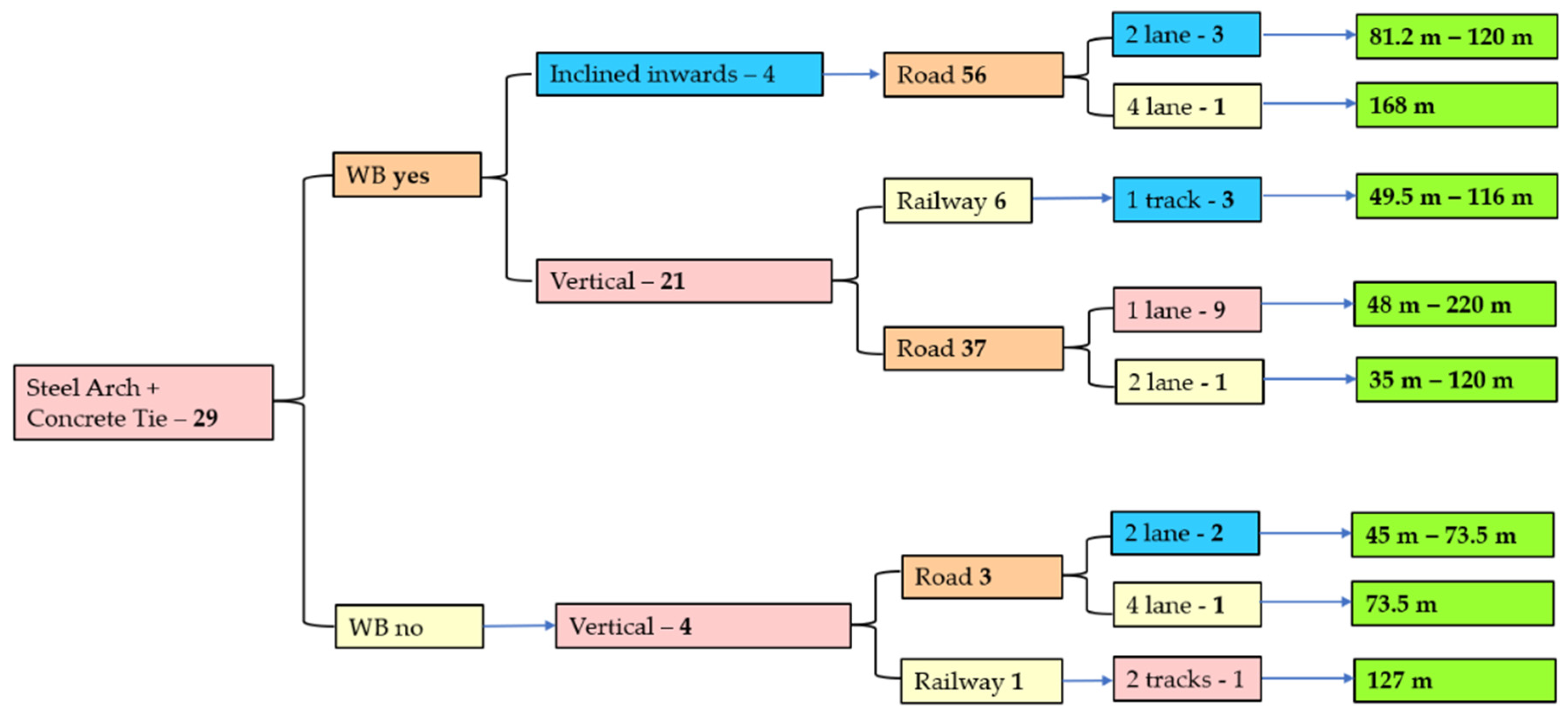
Most of the Network Arches built, 142 structure identified worldwide, have the arch made of steel, in most cases the cross-section is a tubular or box cross-section, and the tie is made of steel or a composite cross-section with the deck. Figure 21 and Figure 22 make a classification according to the presence or absence of the WB, position of the arches in the vertical plane, type of bridge (railway, road, combines or pedestrian), number of lanes and span range. A similar approach is used to present the situation of the 30 structures built using the “classical NAB” solution proposed by prof. Tveit, with the arch made of steel and the tie in concrete, Figure 23.
In case of steel Arches with a composite deck, in the absence of WB, the span range is smaller, from 22 m to 162 m. For the same structural system, in the presence of WB, with the arches vertical, the span range varies from 22 m to 268 m, an increase of 65% of the span covered. With the inclination inwards of the arches, the span varies from 44 m to 420 m, that translates into an increase with 250% compared to the case of no WB and of 156% compared to the case of vertical arches with WB.
The case of steel arch with a concrete deck, presented in Figure 23, shows a span range varying from 35 m to 220 m for the slenderest NAB in the world, the Brandanger bridge, with the remark that such a slender structure was possible due to the low values of the traffic load, as the bridge was designer for 1 lane, with a deck of only 5 m.
Figure 21.
Network Arches with Steel Arches and Steel Tie/Composite Deck.
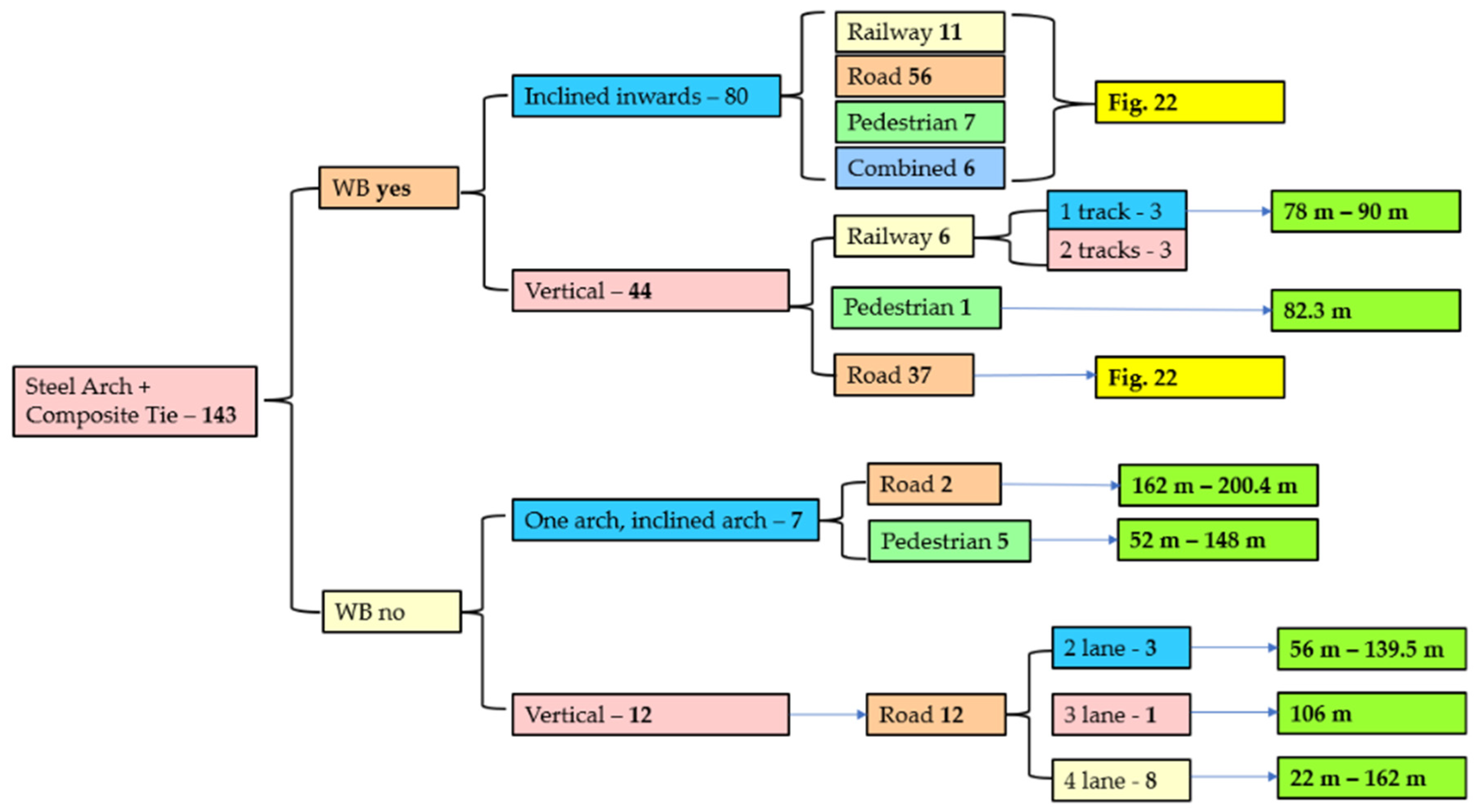
Figure 22.
Network Arches with Steel Arches and Steel Tie/Composite Deck. Continuation of Figure 21.
Figure 22.
Network Arches with Steel Arches and Steel Tie/Composite Deck. Continuation of Figure 21.
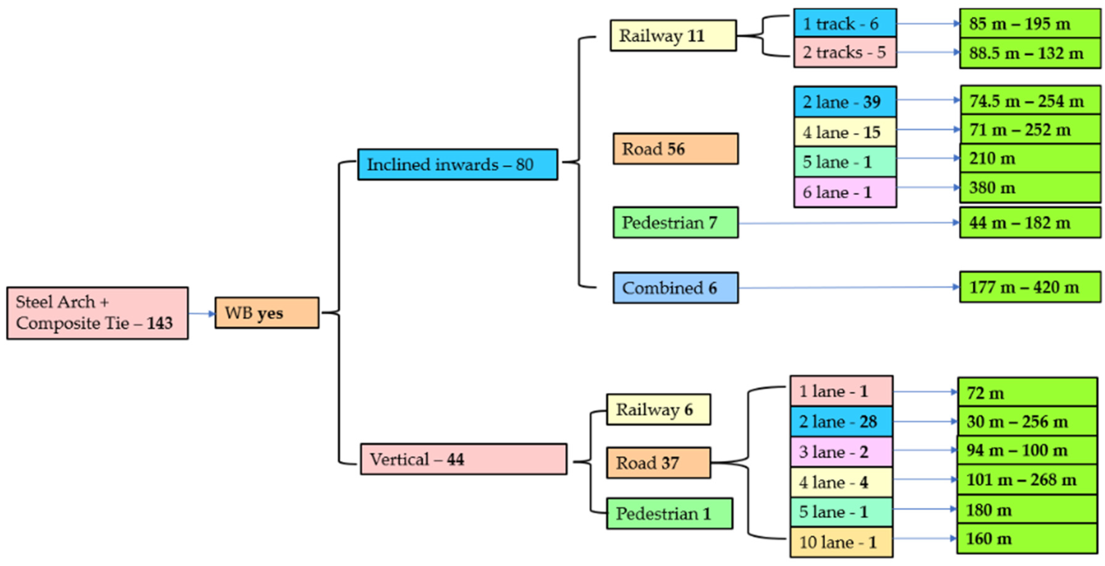
Figure 23.
Network Arches with Steel Arches and Concrete Tie.
4. Research on Network Arch Bridges
4.1. Network Arch Bridges in Timber
The first Network Arch in timber, Steien Bridge was opened to traffic in 2016, in Norway [45,46] and to this day, it is the longest NAB with glulam arches, with a span of 88.2 m. The other network arches in timber are also in Norway, 2 of the bridges are road bridges with spans of 70 m and 34 m and a footbridge with a 52 m span. Even though Steien Bridge was the first timber NAB to be built, researchers’ interest into the use of glulam for network arches started years before. At the 8th International Conference on Timber Engineering, TCTE, held in Lahti, Finland, in 2004, Bell and Wolleback presented 2 papers [45,46] investigating the analysis of a network arch bridge with glulam arches with a span of 80 m. The conclusion in [45] was that if the overall stability of the system can pe proven, the design could be viable. The deck solution adopted is presented in [46], having as a starting point the deck of a timber bridge already built. In [46] the 3D model is analyzed with respect to the in-plane and out-of plane buckling analysis. The similarities and differences between the 2D analysis [45] and the 3D analysis were presented, and the overall conclusion was that the suggested design has sufficient stability properties [46].
In 2012, a master thesis was finished at Lund University investigating glulam arches [47]. The study performed has some limitations, but it proved again the possibility to use timber as the material of choice for the arch.
One year later, in 2013, at the International Conference on Timber Bridges held in Las Vegas, Nevada, USA, the first Network Arch built with timber arches was presented [41] and Malo and Ostrycharczyk presented the first of a series of papers investigating glulam NABs. In [48] the scaled laboratory model of a bridge was presented, together with measured and numerically obtained vibrational modes in the vertical and horizontal direction of the timber deck. Ostrycharczyk under the supervision of prof. Malo continue her studies and received her PhD from the Norwegian University of Science and Technology in 2017. In her doctoral thesis, Ostrycharczyk studied the case of NAB with light timber deck in transverse crossbeams [49] and introduced new hanger arrangements suitable for this type of bridge: the modified radial pattern and the “spoked wheel configuration of hangers”. In the spoked configuration, there are 2 sets of inclined hangers that have a coinciding point of fastening on the arch, while their fastening point on the deck is in the same longitudinal plane, but in different points on the crossbeam. That leads to the hangers to be inclines in and out of the plane of the arch. She also made a scaled model of one of the proposed configurations that was tested and used to calibrate numerical models. The results of the study [48] were published in a series of papers [50,51,52,53]. In [54] the steps taken to choose the actual configuration of a network arch timber footbridge are shown, starting with the hanger configuration evaluated in the first step to other aspects involving the bridge design and erection. The case shown is the Vala Footbridge in Norway, with a span of 52.5 m, a width of 5.9 m and an arch rise of 8.4 m.
Another group compared a glulam arch they developed with a similar steel arch to determine the environmental benefits of timber arches using life cycle assessment [55]. With the only modification in the bridge being the arch, the timber arch has a reduction of CO2 emissions to 20% compared to a similar steel arch.
The most recent study published on timber NAB is a master thesis from Sweden [56] assessing the performance of timber arch footbridges with different hanger configurations.
4.2. Netowrk Arch Footbridge
As stated in subsection 3.11, to this point 15 of the NABs around the world were built to sustain pedestrian and cyclist traffic. Except for N-II Footbridge [57] in Madrid, Spain, that was opened to traffic in 2007, all other pedestrian structures were opened to traffic after 2010.
Extensive research into pedestrian NABs was conducted by Belevicius at. All [58,59,60,61]. The scope of their research was to find the optimal construction scheme of pedestrian radial network arch bridges of moderate spans, 30, 45, 60, 75 and 90 m [61]. The optimal scheme of the NAB was found by seeking the minimum mass of the whole bridge. Their findings for pedestrian structures were different than the recommendations for road and railway bridges: the rise to span ratio is set in the interval 0.2-0.3, the number of hangers should be higher than 40 even for short spans and the optimal range of spread angles is 30 to 400 between the hangers. From a mathematical perspective, they employed a stochastic evolutionary algorithm to solve the global optimization problem formulated. In [60] 220 optimal parameter sets for steel radial network arch footbridges were given. For each set, the arch rise, number of hangers, the spread angle of the hangers and the dimensions of the arch, tie and hangers are provided. In [62] another optimization approach based on a genetic algorithm is proposed to find the hanger arrangement.
4.3. Stability analysis
The first to address the critical in-plane buckling load of network arches was Schanack in [63], for the case with no hanger relaxation. He derived a formula for assessing the critical elastic in-plane buckling load on network arches, with the load over the entire span of the bridge. The design formula derived was verified in some network arches already built and the variation compared to the finite element analysis was smaller than 5%.
The out of plane behavior of network arch bridges was addressed in [64] as part of a method to assess the elastic buckling design of NAB. The proposed method was developed for arches with K shape bracings. The paper develops a set of formulas to assess the critical buckling force. The proposed formulation has a maximum error of 10% in respect to several refined FE results in comparison to the simplified formulation in EC3 that shows large overestimation of the instability strength (up to 70% error compared to finite element analysis).
Another group studied the post-buckling of NABs subjected to vertical loads [65]. Their study was conducted for a 100 m long bridge with a width of 10 m and a rise to span ration of 0.2 and the shape of the arch a parabola. The study includes three analyses: a linear elastic buckling analysis, followed by a nonlinear analysis considering the geometrical nonlinearity and, finally, a pushover analysis with the purpose of evaluating the global out-of-plane capacity of the arch. The behavior of the arch is considered under traffic loads, no seismic force was considered. Also, the study includes a scenario with cable loss. The dynamic behavior of the arch observed is similar for one or two broken cables, the main difference in case of two broken cables is in the amplitude of the out-of-plane displacement of the arch. The dynamic response of the arch is influenced by the position of the broken cable. Such a scenario near the abutments increases the dynamic sensitivity of the arch. On the other hand, a cable loss near the center of the arch can reduce the lateral buckling capacity up to 25% in case of slender arch cross-sections. Another group of authors investigated the behavior of NABs subjected to cable loss under moving loads [66,67]. The method chosen was a simplified static analysis of the 2D structure without the broken cable, subjected to dead and live loads, followed by two static forces that reproduce the dynamic effect of the sudden loss. For the bridge studied, the maximum displacement of the tie in case of sudden cable loss was found to be near the sides of the bridge, at 2/5*L and 3/4*L, where L is the span of the bridge.
The most recent research into the nonlinear buckling analysis of NABs was conducted by Blonka et. all [68]. They compared the critical buckling factor from a linear and nonlinear buckling analysis. Nonlinear buckling analysis takes into account the nonlinear behavior of the cables. As their requirement was to find the limit point, third order theory analysis was chosen, providing more accurate results for slender structure in case of large deflection, such are the case of cables. The study was conducted for the bridge over the Vistula River in Cracow and the vertical live load is the train load model from Eurocode, LM71. One interesting conclusion of their study, that is worth investigating in the future, is that additional tension in the hangers, above the forces resulting from self-tensioning, decrease the value of the critical load factor.
4.4. Hanger arrangement
The hanger arrangement of the Network Arch Bridge is the oldest research topic for such structures, but as spans, rise to span ratios, materials used and bridge cross-sections are diverging from the idea of Tveit and all [1,2,3,4,5,6,7,8,9,10,11,12,13,14,15,16,17], the issue of hanger arrangement appears in a series of other studies [49,50,51,52,53,56]. Papers published on the hanger arrangement and not mentioned so far, are [69] where Brunn and Schanack make a summary of their doctoral studies, showing advantages and disadvantages of the 5 proposed hanger arrangements in terms of both structural response and user-friendliness. In [70] another group presents a comparison for a concrete filled steel tubular arch between the classical vertical disposition of the hangers, the Fan arrangement, and the Network arrangement with parallel inclined hangers. A comparison between a 90 m tied arch bridge with vertical hangers, 3 different Nielsen configurations of the hangers and the Network hanger configuration for parallel hangers with the slope angle 500 – 700 is given in [71]. The case of a 100 m tied arch bridge inclined inwards with 150O is given in [72] where a comparison is made between the arch with vertical hangers for a varying number of hangers from 5 to 50 and for the Network arrangement with parallel inclined hangers. The skew angle of the hangers was set to 40O and the number of hangers varied from 40 to 85. The research presented was part of a doctoral thesis [73] and the configuration studied is part of a road bridge opened to traffic in 2022, the Bridge at Ulmeni across the Somes River, in Romania. In [74] a comparison between different hanger arrangements for a proposed road bridge with a span of 80 m with circular hollow cross-sections is given. The configurations studied were for 20, 22 and 24 hangers with a constant angle increase of 1.5O and the radial arrangement for 20, 22 and 24 hangers with the angle of 38O between the hanger and the radius. Another study [75] shows that a parabolic arch with two sets of radial hangers have a good behavior in terms of resistance for small rise to span ratio, compared to elliptical arches that show poor performance in both strength and serviceability.
In any bridge design a great deal of time is spent in finding the optimal configuration given the required span and other constraints. Two different groups of researchers worked in finding optimization models for the NAB. In [76] an optimization model based on a three-step algorithm is given, with the remark that the procedure used does not ensure, a priori, a global optimum. In [77] another optimized design using a global optimization algorithm (EVOP) is presented. EVOP is interfaced with Ansys to evaluate the structural response of the bridge. It was observed that a reduction of 38-40% of the total cost can be saved for both circular and parabolic arches in case of the optimized design.
4.5. Other research about the Network Arch Bridge
Asymmetric NAB were studied in [78], where the asymmetry is defined as an arch not symmetric to its center plane. A 100m long asymmetric road arch bridge was chosen for the study, with a concrete tie/deck. The principal difference seen was on the value of the compressive force, smaller in the steep side of the arch and larger where the shape of the arch is less curved. Even in the case of asymmetric arches, the overall behavior of a NAB in terms of bending moment distribution remains unchanged.
An interesting idea was proposed by Valenzuela and Casas [79] to use network arches as strengthening of existing old beam bridges on multiple spans where the piers are affected by scour and erosion. By chaining the structural system, the intermediate infrastructures are eliminated, therefore the erosion of piers is no longer a problem. The paper describes the steps needed to modify the superstructure and the design criteria.
A series of paper describe the construction of German network arch bridges [80,81]. In [80] the experience with the construction of a series of railroad NAB across Germany is presented: Rosenbachtal Bridge, opened in 2008, is an 89 m arch bridge that carries 1 railway track and has a hanger net of 36 flat steel hangers; Oder River Bridge, also known as the Frankfurt Railroad Bridge, opened also in 2008, has a span of 104 m, carries 2 railway tracks and it was designed with 26 flat steel hangers; the B6 Railroad Overpass, opened in 2009, has a span of 79 m, it carries 1 railway track and has 24 flat hangers on each arch; Flora Bridge, opened in 2010, is a network arch with a span ok 132.60 m and 30 flat steel hangers that caries 1 railway track. Brieselang Bridge is a highway network arch bridge completed in 2011, with a span of 106 m and a radial arrangement of the hangers. Brieslang Bridge is comprised of two independent NABs, one for each motorway direction. In [81] aspects regarding the design and the construction work are presented.
In [82,83,84] a series of Network Arch Road overpasses in Poland are presented, with the arch rib made of hot-rolled profiles and the deck a longitudinally prestressed concrete slab. The 4 overpasses have spans varying from 62 m to 75 m and were opened to traffic in 2008 and 2009. Based on the experience gained at that time, a new overpass with a span of 120 m was constructed over the Lyna River, with the arches made of HD 400x744 and HD 400x1086 hot rolled profiles in steel grade S46o [84]. In 2018, a railroad NAB with a span of 116 m was erected in Krakow, using as the arch cross-section HD400x1299 profiles.
The two network arches that are part of the Vienna Central Railway Station Bridge, both sustaining a double track railway, with spans of 88.5 m and 112.5 m are presented in [85,86]. Structural considerations, the form of the arch and the hanger arrangement, together with the bending moment and axial forces diagrams are given in [85] and details from the constructor, in relation to the erecting method used are given in [86].
River Irwell Crossing, the first NAB built in United Kingdom, is introduced in [87]. The bridge was designed with a weathering steel box section, the arch axis is circular, and the plate thickness of the cross-section varies from 40 mm to 60 mm. The form of the bridge was dictated by esthetic conditions as well; the arch on the main span has an apparent continuation on the approach span. The technical report [87] gives insight into all the stages of the bridge construction, from the overall concept to the stressing of the hangers.
In another technical report [88] the internationally award-winning design of the Perry Bridge Network Arch, over the Waikato River in New Zeeland is presented. Perry Bridge spans 130 m with two inclined steel tube arches that are braced together. The rise of the bridge is 18 m, thus leading to a rise to arch ratio of 0.138, while most NAB designs are in the range 0.15 to 0.20, even higher in case of timber arches. The hanger arrangement is particular to this structure, as the hanger angles were varied to provide some of the benefits of the radial arrangement but maintaining regular connection along the deck. The bridge was nominated for many awards, the most notable being the Structural Awards 2018, at the Institution of Structural Engineers in London where it won the excellence in the design of pedestrian and/or cycle bridges.
5. Conclusions
This paper provides a review of the literature published about the Network Arch Bridge and gives an insight into the growth of the NAB from the middle of the last century to the present day. Extensive explanations into how the NAB can be built are available online on prof. Tveit website [89]. But no review of the research conducted to the present day was found by the authors. The structures presented briefly were chosen to show the different structural systems adopted by engineers around the world and to give a starting point for those interested in further researching or designing a Network Arch. Also, a large review of the literature regarding the hanger arrangement, the buckling of Network Arches, footbridges, timber NABs is given. No details regarding the construction of NABs were given, as the technology depends a lot on the structural system of the bridge and the technologies used in different structures are presented in detail in the papers of prof. Tveit [1,2,3,4,5,17,21]. The author’s scope was for this paper to gather the information in the literature and not to overlap with already published papers. The evolution of the NAB from the first bridge, the 79.75 m Steinkjer in Norway, opened in 1963, to the slenderest NAB in the world, the 220 m Brandanger in Norway opened in 2010, to the 380 m Bugrinsky Bridge in Rusia, opened in 2014, and to the 420 m Qilu Huanghe River Bridge that is under construction in China shows the potential the Network Arch has to span larger and larger distances.
Author Contributions
“Conceptualization, A.D.D.; methodology, A.D.D., S.I.G. and C.M.; investigation, A.D.D.; resources, M.C. and M.D.; writing—original draft preparation, A.D.D.; writing—review and editing, M.C..; visualization, V.M..; supervision, S.I.G.; project administration, A.D.D.; funding acquisition, M.D. All authors have read and agreed to the published version of the manuscript.” to the work reported.
Funding
“This research was funded by SC DIFERIT SRL, grant number 39029/24.11.2022” and “The APC was funded by the Technical University from Cluj-Napoca”.
Institutional Review Board Statement
“Not applicable”
Informed Consent Statement
“Not applicable”.
Data Availability Statement
“Not applicable”..
Acknowledgments
The first author would like to express her gratitude to Professor Per Tveit for the two encounters they had. The first in 2006 in Trondheim, and the second in 2019 in Grimstad, Norway. Professor Tveit is a true inspiration for engineers working in the field of bridge engineering and the ideas they exchanged led to this project.
Conflicts of Interest
The authors declare no conflict of interest.” “The funders had no role in the design of the study; in the collection, analyses, or interpretation of data; in the writing of the manuscript, or in the decision to publish the results”.
References
- Tveit P., dr. ing. Docent Emeritus, Agder University, Grimstad, Norway. About the Network Arch. Personal communication, Second edition January 2011.
- Tveit P., dr. ing. Docent Emeritus, Agder University, Grimstad, Norway. The Network Arch. Bits of Manuscipt in March 2014 after Lectures in 50+ Countries. Personal communication, 2014.
- Map of Network Arch Bridges. Available online: URL (accessed on 24.08.2023).
- Nielsen, O.F. Foranderlige Systemer med anvendelse på buer med skraatstilledeHængestenger, (Discontinuous systems used on arches with inclined hangers). PhD Thesis, Gad Copenhagen, 1930, in Danish.
- Tveit P,. How to design economical network arches. IOP Conference Series: Materials Science and Engineering 2019, 471, 052078. [CrossRef]
- Larsse R.M., Jakobsen K.A., Brandangersundet Bru – verdens slankeste?, Nyheter om Stalbyggnad nr. 3, 2006, Innehall, pp. 37-40, in German.
- Teich S., Wendelin S., Vergleichsrechnung einer Netzwerkbogenbrückeunter Einsatz des Europäischen Normenkonzeptes., Diplomarbeit, Technische Universitat Dresden, 21 August 2001, in German.
- Steinmann U., Berechnung und Konstruktion einer stahlernen Eisenbahn-Stabbogenbrucke mit Netzwerkhangern, Diplmarbeit, Technische Universitat Dresden, in cooperation with Agder University College in Grimstad, Norway, September 2002, in German.
- Brunn B., Schanack F., Calculation of a double track railway network arch bridge applying the European standards. Master Thesis, Dresden University of Technology, Germany, defended in Grimstad, Norway, August 2003.
- Teich S., Beitrag zur Optimierung von Netzwerkbogenbrucken. Contribution to Optimizing Network Arch Bridges. PhD Thesis, Dresden, 2012, in German.
- Niklison A.J., Statical Analysis of Network Arch Bridges, Master Thesis, Stuttgart, 2010.
- Varennes M., Design of a single-track railway network arch bridge, Maser thesis, Stockholm, 2011.
- Rack M., Entwurf einer kombinierten Strassen-Eisenbahn-Netzwerkbogenbrucke, Diploma thesis, Dresden and Grimstad, 2003, in German.
- Da Costa B.N., Design and Analysis of a Network Arch Bridge, Tecnico Lisboa, Lisbon, Master Thesis, October 2013.
- Tveit P., Graduation thesis on arch bridges with inclined hangers, Technical University of Norway, Trondheim, September 1955.
- Tveit P., Arch bridges with inclined intersecting hangers. PhD. Thesis, Technical University of Norway, Trondheim, 1959, in Norwegian.
- Tveit P., Systematic Thesis on Network Arches 2014. Personal communication. Available online: URL http://home.uia.no/pert. Accessed at 21.07.2023.
- Yousefpour H., Helwig T.A., Bayrak O. Construction stresses in the world’s first precast concrete network arch bridge. PCI Journal, 2015, vol 60 (5), pp. 30-47. [CrossRef]
- Yousefpour H., Gallardo J.M., Helwig T.A., Bayrak O. Innovative precast, prestressed concrete network arches: Elastic response during construction. Structural concrete 2017, Vol 18, pp. 768-780. [CrossRef]
- Janata, V., Gregor, D., Sasek, L., Nehasil, P., Wangler, T., New Troja Bridge in Prague – Structural Solution of Steel Parts. Procedia Engineering 2012, Vol. 40, pp 159-164. [CrossRef]
- Tveit, P.; Construction of the Troja Bridge in Prague. Personal communication. Available online: https://home.uia.no/pert/data/Troja_bridge.pdf (accessed on 13th of June 2023).
- Gregor, D., Janata, v., Sasek, L., Nehasil, P., Broz, R. New Troja Bridge – Concept and Structural Analysis of Steel Parts, Procedia Engineering 2012, Vol. 40, pp 131-136. [CrossRef]
- Larssen R.M., Jakobsen S.E., Brandangersundet Bridge – A slender and light network arch, Taller, Longer, Lighter, IABSE-IASS-2011 London Symposium Report.
- Ronnquist, A., Naess, A. System reliability analysis of slender Network Arch Bridges. In Proceedings of the Computational Methods in Structural Dynamics and Earthquake Engineering, Kos Island, Greece, 12-14 June 2013.
- Ronnquist, A., Naess, A. Global Buckling Reliability Analysis of Slender Network Arch Bridges: An Application of Monte Carlo-Based Estimation by Optimized Fitting, In: Gardoni, P. (eds) Risk and Reliability Analysis: Theory and Applications. Springer Series in Reliability Engineering, 2017, Springer, Cham. [CrossRef]
- Millanes, F M., Ortega, M., Carnerero, A. Palma del Rio Arch Bridge, Cordoba, Spain. Technical Report in Structural Engineering International, 2010, Vol. 3, pp. 338-342. [CrossRef]
- Millanes, F., Ortega, M., Carnerero, Project of two metal arch bridges with tubular elements and network suspension system, steel bridges: Advanced solutions & technologies. In 7th International Conference on Steel Bridges Proceedings, Guimaraes, Portugal, 4-6 June 2008.
- Mato, F. M., Cornejo, M. O., Agromayor, D. M., Perez, P. S. The use and development of the Network Suspension System for Steel Bowstring Arches, Proceedings of the IVth Congresso de Construçao Metálica e Mista (cmm-associaçao Portuguesa de Construçao Metálica e Mista), Lisbon, Portugal, 2008, II-97/106.
- Mato, F. M., Cornejo, M. O., Sanchez, J. N. Design and Construction of Composite Tubular Arches with Network Suspension System: Recent Undertakings and Trends. Journal of Civil Engineering and Architecture, 2011, Vol 5 (30), pp. 191-214. [CrossRef]
- World’s first Network Arch Bridge with CFRP hangers. https://www.compositesworld.com/news/german-railway-bridge-suspended-on-cfrp-hangers. Accessed online at 27.07.2023.
- Haspel, L. Bauen mit Zuggliedern aus Carbon in Proceedings 14. 14. Fachtagung Baustatik – Baupraxis, Stuttgart, 8-9.05.2021.
- Haspel, L. Netzwerkbogenbrücken mit Hängern aus Carbon. Stahlbau, 2019, Vol. 8, Heft 2, S 153-159. [CrossRef]
- Keil, A., Haspel, L. Stadtbahnbrucke - built innovation: an integral supported network arch with CFRP hangers. Bautechnik, 2021, Vol. 98, H. 2, S. 149–158. [CrossRef]
- Haspel, L. Carbon network arch - lessons from the first use of carbon network cables. Stahlbau, 2022, Vol. 91 ,H. 2, S. 84–94. [CrossRef]
- Meier, U.O., Winistorfer, A. U., Haspel, a. World’s first large bridge fully relying on carbon fiber reinforced polymer hangers. SAMPE Conference, The Future Composite Footprint, Amsterdam, 30.09-01.10.2020.
- German Civil Engineer Award, 2022. URL:https://www.sbp.de/en/news/stadtbahnbruecke-in-stuttgart-erhaelt-deutschen-ingenieurbaupreis-2022. Accessed online at 27.07.2023.
- Bojovic, A., Mora Munoz, A., Markovic, Z., Aleksic, D., Pavlovic, M., Spremic, A. Railway Road Bridge in Novi Sad – Design and Erection. 37th IABSE Symposium Madrid, 2014. [CrossRef]
- Bojovic, A., Mora, Markovic, Z., Pavlovic, M., Novakovic, N., Spremic, M. Railway Road Bridge in Novi Sad. Steel Tied network arches across the Danube. IOP Conference Series: Material Science and Engineering, 2018, 419 (11), 0120032. [CrossRef]
- SHM system of the Zezelj (Novi Sad) Bridge. URL: https://www.hbkworld.com/en/knowledge/resource-center/case-studies/2023/bridge-monitoring-an-example-from-hbm#!ref_www.hbm.com. Accessed online at 28.07.2023.
- Veie, J., Bjertnaes, M., Stensby, T. A. New dimensions in bridge construction in Norway. Internationales Holzbau-Forum IHF, 2015.
- Veie, J., Abrahamsen, R. B. Steien Network Arch. International Conference on Timber Bridges, Las Vegas, Nevada, USA, 2013.
- Zhou, W., Senior Eng., Chen, L., Professional Senior Eng., Shao, C., Chief Eng., Wu, X., Senior Eng. A Long-span Network Arch Birdge for Road and Rail Traffic, Structural Engineering International, 2022, 32 (2), 211-215. [CrossRef]
- Lai, Y., Li, Y., Huang, M., Zhao, L., Chen, J., Min Xie, Y. Conceptual design of long span steel-UHPC composite network arch bridge. Engineering Structures, 2023, Elsevier, Vol. 277, 115-434. [CrossRef]
- Steere, P., Wu, Y. Design and construction of the Providence River Bridge. 25th Annual International Bridge Conference Engineers’ Society of Western Pennsylvania Pittsburgh, 2.06 – 4.06, 2008.
- Bell, K., Wollebaek, L. Large, mechanically joined glulam arches. The 8th World Conference on Timber Engineering WCTE 2004, Lahti, Finland, 14.06-17.06.2004.
- Wollebaek, L., Bell, K. Stability of glulam arches. The 8th World Conference on Timber Engineering WCTE 2004, Lahti, Finland, 14.06-17.06.2004.
- Nylander, E. A feasibility study of a network arch bridge with glulam arches. Master Thesis, Rapport TVBK-5211, ISSN 0349-4969, Lund University, 2012. [Google Scholar]
- Malo, K.S., Ostrycharczyk, A., Barli, R., Hakvag, I. On development of network arch bridges in timber. International Conference on Timber Bridges, Las Vegas, Nevada, USA, 2013.
- Ostrycharczyk, A.V. Network arch timber bridges with light timber deck on transverse crossbeams. PhD thesis. Norwegian University of Science and Technology, Trondheim, November 2017.
- Ostrycharczyk, A.V., Malo, K.A. Comparison of network patterns suitable for timber bridges with crossbeams. Proceedings of ICTB, 3rd International Conference on Timber Bridges, Skelleftea, Sweden, 26.06-29.06.2017.
- Ostrycharczyk, A.V., Malo, K.A. Parametric study of radial hanger patterns for network arch timber bridges with a light deck on transverse crossbeams. Engineering Structures, 2017, 153, 491-502. [CrossRef]
- Ostrycharczyk, A.V., Malo, K.A. Parametric study on effects of load position on the stress distribution in network arch timber bridges with light timber decks on transverse crossbeams. Engineering Structures, 2018, 163, 112-121. [CrossRef]
- Ostrycharczyk, A.V., Malo, K.A. Network arch timber bridges with light timber decks and spoked configuration of hangers – parametric study. Engineering Structures, 2022, 253, 113-782. [CrossRef]
- Ostrycharczyk, A.V., Vaernes, A. Vala bridge – Timber network arch footbridge in Ringebu, Norway. Conference Proceedings. 4th International Conference on Timber Bridges ICTB 2021 Plus, Biel/Bienne, Switzerland, 9-12.05.2021.
- O’Born, R., Vertes, K., Pytten, G., Hortemo, L.O., Braendhagen, A. Life cycle assessment of an optimized network arch highway bridge utilizing timber. 10th Conference on the Bearing Capacity of Roads, Railways and Airfields, Athens, Greece, June 2017.
- Garcia, A.G. A parametric study of the static and dynamic performance of timber arch footbridges with different hanger configurations. Master thesis. KTH Royal Institute of Technology, Stockholm, Sweden, 2022.
- Mato, F.M., Rubio, L.M., Sanchez, J.N. Bowstring footbridges in the cycling ring road in Madrid. Presented at 3rd International Conference on Footbridges. Footbridge 2008 – Footbridges for Urban Renewal. Porto, Portugal, 133-134, 2-4.07.2008.
- Belevicius, R., Juozapaitis, A., Rusakevicius, D. Parameter Study on Weight Minimization of Network Arch Bridges. Periodica Polytechnica Civil Engineering, 2018, 62(1), pp.48-55. [CrossRef]
- Belevicius, R., Juozapaitis, A., Rusakevicius, D., Zilenaite, S. Parametric study on mass minimization of radial network arch pedestrian bridges. Engineering Structures, 2021, 237, 112-182. [CrossRef]
- Belevicius, R., Juozapaitis, A., Rusakevicius, D., Zilenaite, S. Optimal schemes of radial network arch pedestrian bridge: An extensive dataset of solutions under different conditions. Data in Brief, 2021, 36, 107-149. [CrossRef]
- Belevicius, R., Rusakevicius, D., Valentinavicius, S. Insights into Optimal Schemes of Radial Network Arch Pedestrian Bridge. Advances in Civil engineering, 2022, Hindawi, Aritcle ID 6951775, 12 pg. [CrossRef]
- Tan, YG., Yao, YB. Optimisation of hanger arrangement in pedestrian tied arch bridge with sparse hanger system. Advances in Structural Engineering, Vol 22 (12), 2594-2604, 2019. [CrossRef]
- Schanack, F. Calculation of the critical in-plane buckling load of network arches. Bautechnik, 2009, 86 (5), pp 249-255. [CrossRef]
- Lonetti, P., Pascuzzo, A. A practical method for the Elastic Buckling Design of Network Arch Bridges. International Journal of Steel Structures, 2020, 20 (1), 311-329. [CrossRef]
- Zampieri, P., Tetougueni, C. D., Maiorana, E., Pellegrino, C. Post-buckling of network arch bridges subjected to vertical loads. Structure and Infrastructure Engineering, 2021, Vol 17 (7), 941-959, Taylor&Francis. [CrossRef]
- Bruno, D., Lonetti, P., Pascuzzo, A. A numerical study on network arch bridges subjected to cable loss. International Journal of Bridge Engineering, 2018, 6 (2), pp. 41-59.
- Ammendolea D., Bruno, D., Greco, F., Lonetti, P., Pascuzzo, A. An investigation on the structural integrity of network arch bridges subjected to cable loss under the action of moving loads. Procedia Structural Integrity, 2020, 25, pp. 305-315. [CrossRef]
- Blonka, A., Skretkowicz, L. Nonlinear buckling analysis of network arch bridges. Studia Geotechnica et Mechanica, 2022, 44 (2), 123 – 137. [CrossRef]
- Schanack, F., Brunn, B. Generation of network arch hanger arrangement. Stahlbau, 2009, Vol. 78 (7), pp. 443-522. [CrossRef]
- An, L.h., Duy, D.M. Research on the hanger arrangement for the concrete filled steel tubular arch bridge with rod and roadway located under arch rib. Sustainable arch bridges, 3rd Chinese-Croatian Joint colloquium on Sustainable Arch Bridges, Zagreb, Croatia, 15-16.07.2011.
- Danciu, A.D., Gutiu, S.I., Moga, C. Bi-dimensional analysis of a 90 m arch with different hanger arrangements. In Nano, Bio and Green – Technologies for a sustainable future conference Proceedings, SGEM 2016, Vol. 2, pp. 477-484, Bulgaria, 2016.
- Vlad, M., Kollo, G., Marusceac, V. A modern approach to tied-arch bridge analysis and design. Acta tehnica Corviensis – Bulletin of Engineering, 2015, Tome VIII (4), pp. 33-37.
- Vlad, M. Study on concept and design of cable structures. PhD Thesis, Technical University of Cluj-Napoca, Cluj, Romania, 2019. In Romanian. [Google Scholar]
- Danciu, A.D., Gutiu, S.I., Moga, C, Bucerzan, M. Comparative Analysis between the Hanger Arrangement in an 80 m Network Arch Bridge with Circular Hollow cross-sections. In Lecture Notes in Networks and systems, 2022, Vol. 386, pp. 110-119. [CrossRef]
- Bayyavarapu, R., Talukdar, S., Lalthlamuana, R. Effect of rise to span ratio on the Behavior of a Steel Arch Bridge for different types of Hanger Arrangement. Steel and Aluminium Structures, 8th International Conference on Steel and Aluminium Structures (ICSAS), Hong Kong, 7-9.12.2016.
- Bruno, D., Lonetti, P., Pascuzzo, A. An optimization model for the design of network arch bridges. Computer and Structures, 2016, vol 170, pp 13-25. [CrossRef]
- Islam, N., Rana, S., Ahsan, R., Ghani, S. N. An Optimized Design of Network Arch Bridge Using Global Optimization Algorithm. Advances in Structural Engineering, 2016, Vol 17(2), pp. 197-210. [CrossRef]
- Zwingmann, B., Schanack, F., Marx, S. Asymmetric network arch bridges. Stahlbau, 2009, Vol 78(7), pp. 471-476. [CrossRef]
- Valenzuela, M.A., Casas, J.R. Bridge strengthening by conversion to network arch: design criteria and economic validation. Structure and Infrastructure Engineering, 2016, Vol 12 (10), pp. 1310-1322. [CrossRef]
- Gautier, P., Krontal, L. Experiences with Network arches for railway bridges. Stahlbau, 2010, Vol 79(3), pp. 199-208. [CrossRef]
- Degenhardt-Herberger, K., Reinke, K.D. Reconstruction of the motorway bridge over the Havelkanal near Breselang, Germany. Stahlbau, 2012, Vol. 81 (2), pp. 91-U4. [CrossRef]
- Rademacher, D., Ochojski, W., Lorenc, W., Kozuch, M. Advanced solutions with hot-rolled sections for economical and durable bridges. Steel construction – design and research, Vol. 11 (3), pp. 196-204, 2018. [CrossRef]
- Kaczmarek, T., Galewski, T., Topolewicz, K., Sek, R., Radziecki, A, Ochojski, W., Kozuch, M., Lorenc, W. Polish experience with network arch bridges using cold-bent HD sections. Steel construction – design and research, 2020, Vol. 13 (4), pp. 271-279. [CrossRef]
- Zanon, R., Matos, R., Rademacher, D., Lorenc, W. Network arch bridges with rolled sections: ideas for economic and durable detailing. 12th Conference on Steel and Composite Construction, Coimbra, Portugal, Ernst&Sons, pp. 106-116, 21-22.11.2019. [CrossRef]
- Heinlein, M., Einhauser, O. Network arch bridges for the OBB over the central marshalling yard at Vienna-Kledering, Austria – Structural and constructional design of the bridges. Stahlbau, 2013, Vol 82(5), pp. 334-339, 2013. [CrossRef]
- Stelzer, B., Dorrer, G. Two network arch bridges: Connection between the existing railway lines Ostbahn and Flughafenschnellbahn in Vienna, Autrisa – Characteristics form the point of view of steel constructors. Stahlbau, Vol. 82(5), pp. 326-333. [CrossRef]
- Rusev, R., Foster, R., Abbott, T., Bistolas, A. River Irwell Crossing – UK’s First Network Arch Bridge. Structural Engineering International, 2019, Vol 29(2), pp. 309-314. [CrossRef]
- Brook, T., Gaby, P. Perry Bridge Network Arch – Elegance in Efficiency. Structural Engineering International, 2020, Vol 30(2), pp. 250-253. [CrossRef]
- Information on the Network Arch. Available online: https://home.uia.no/pert/index.php/Home (accessed on 25.08.2023).
Figure 1.
Nielsen bridge: (a) Nielsen bridge at Castelmoron in France, 1933. Span on 145m; (b) Design of a bridge with crossing hangers from a patent application in 1926.
Figure 1.
Nielsen bridge: (a) Nielsen bridge at Castelmoron in France, 1933. Span on 145m; (b) Design of a bridge with crossing hangers from a patent application in 1926.
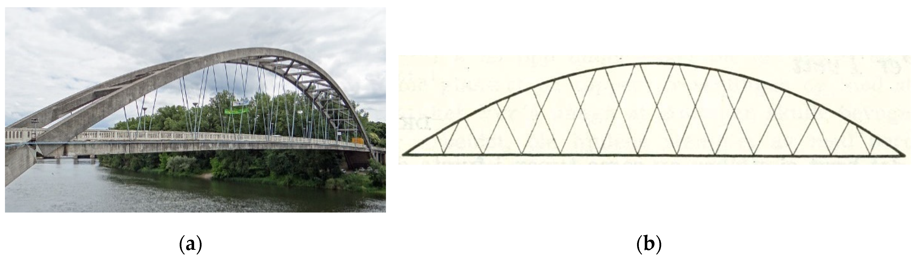
Figure 2.
Reduced curvature of the arch near the supports.
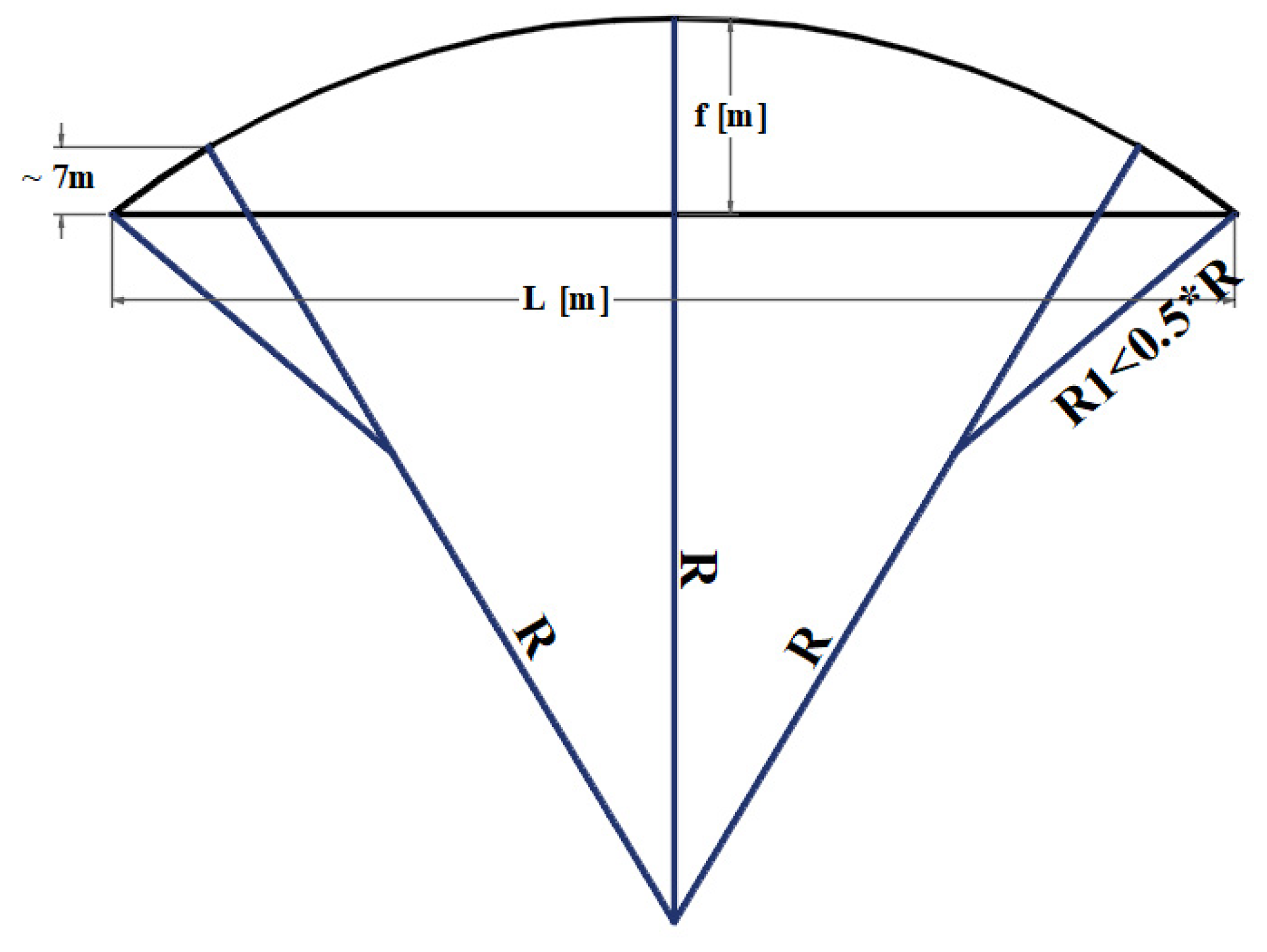
Figure 3.
Universal column versus two box sections for a network arch with a span of 135m [1].
Figure 3.
Universal column versus two box sections for a network arch with a span of 135m [1].
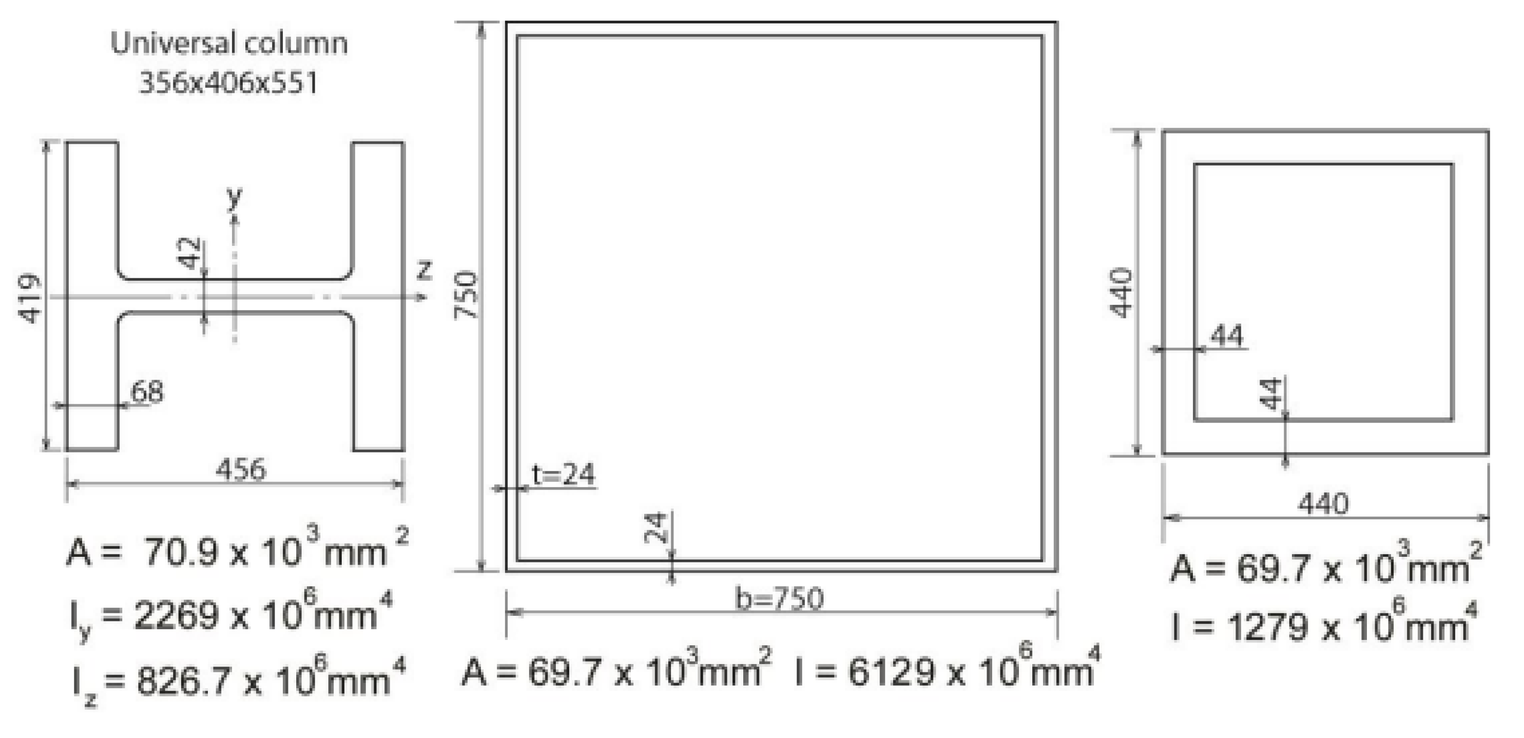
Figure 4.
Shape for the tie and deck [2].
Figure 4.
Shape for the tie and deck [2].

Figure 5.
Necessary thickness of the slab vs the span in the transverse direction [7].
Figure 5.
Necessary thickness of the slab vs the span in the transverse direction [7].
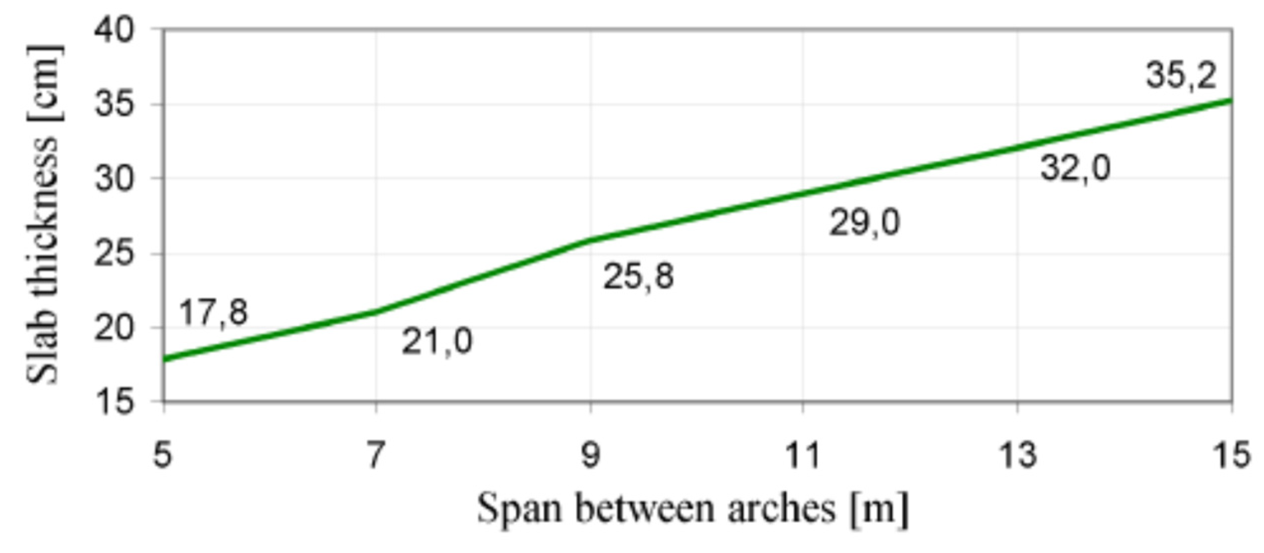
Figure 6.
Hanger arrangement with the help of an ellipse [9].
Figure 6.
Hanger arrangement with the help of an ellipse [9].
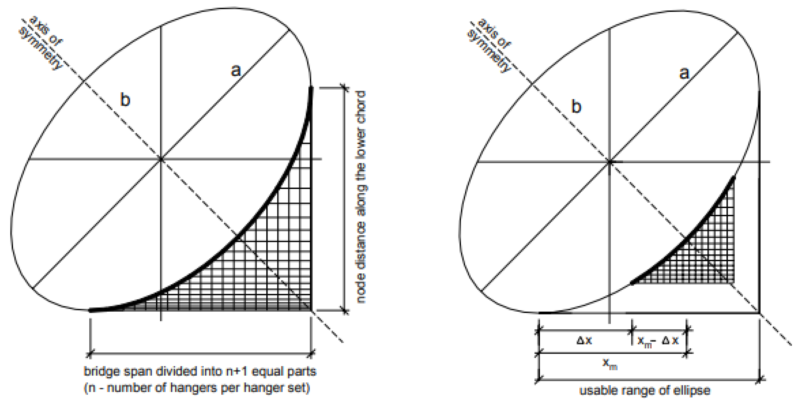
Figure 7.
Hanger arrangement with equally spaced hangers along the arch, a start angle on the tie and the angle change along the tie.
Figure 7.
Hanger arrangement with equally spaced hangers along the arch, a start angle on the tie and the angle change along the tie.
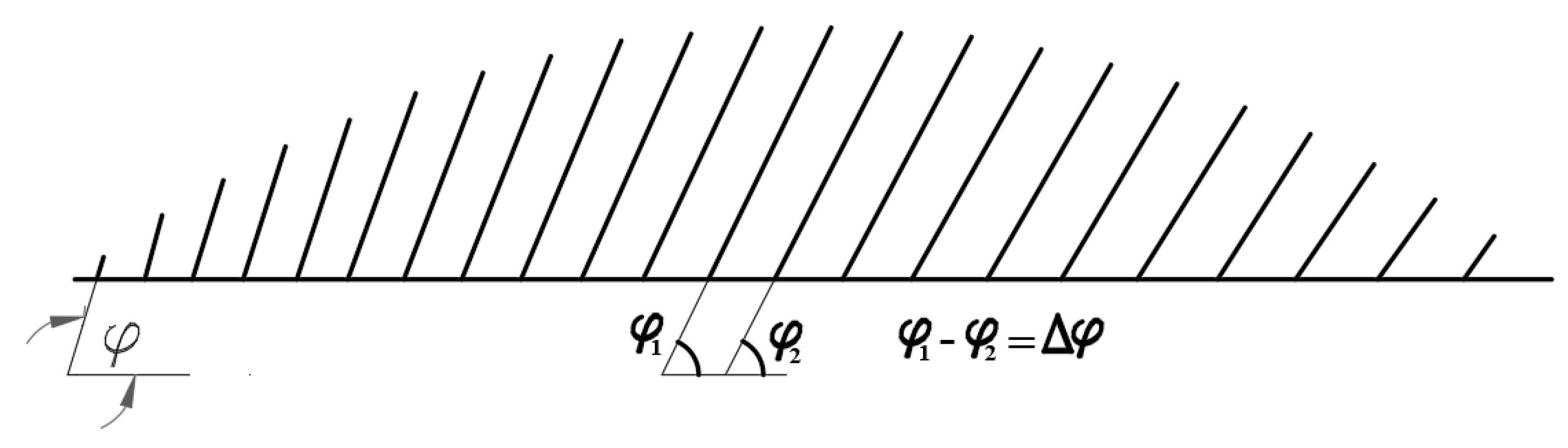
Figure 8.
Radial hanger arrangement: (a) Construction of the radial arrangement; (b) Radial hanger arrangement configuration [7].
Figure 8.
Radial hanger arrangement: (a) Construction of the radial arrangement; (b) Radial hanger arrangement configuration [7].
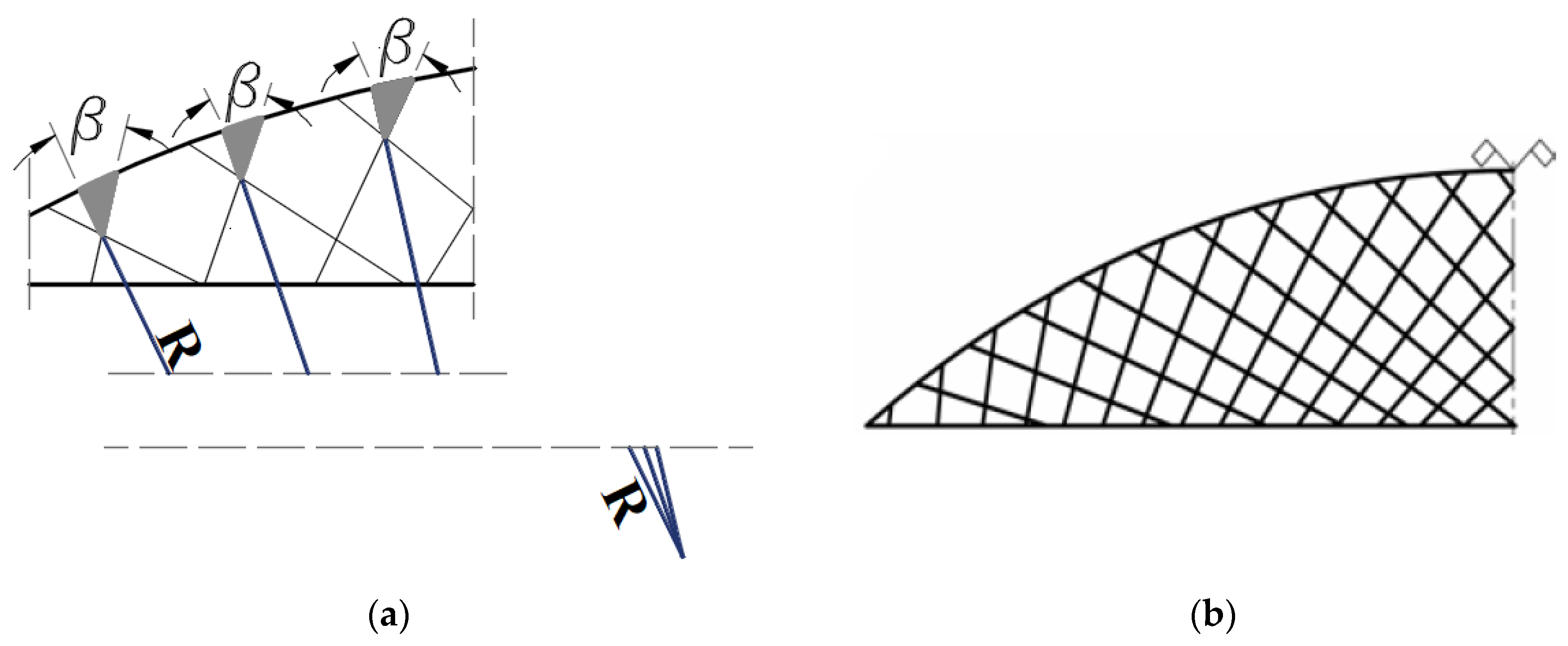
Figure 9.
The Network Arch Bridge at Steiknjer in Norway: (a) Design details [7]; (b) Street view of the bridge.
Figure 9.
The Network Arch Bridge at Steiknjer in Norway: (a) Design details [7]; (b) Street view of the bridge.
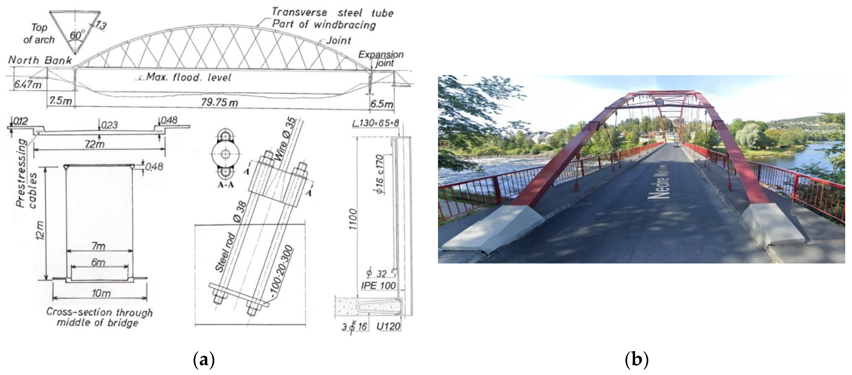
Figure 10.
Street view of the West Seven Street Bridge in Forth Worth, Texas, from Google street view.
Figure 10.
Street view of the West Seven Street Bridge in Forth Worth, Texas, from Google street view.
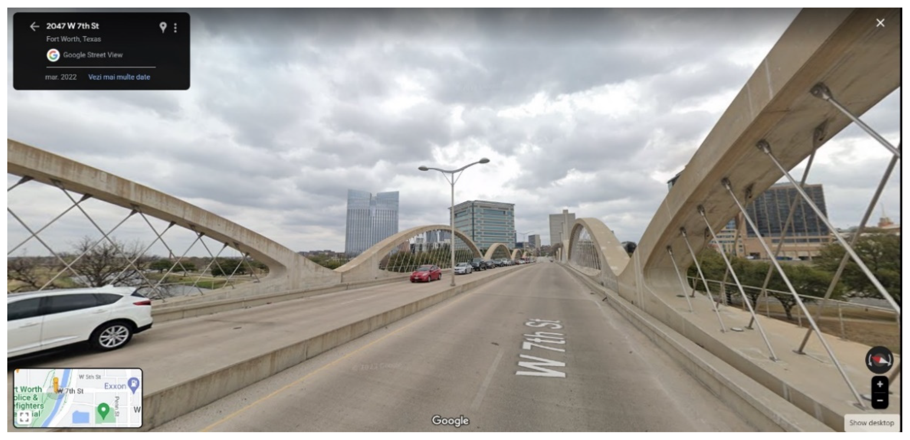
Figure 11.
Street view of the Troja Bridge, Prague, Checz Republic, from Google Street view.
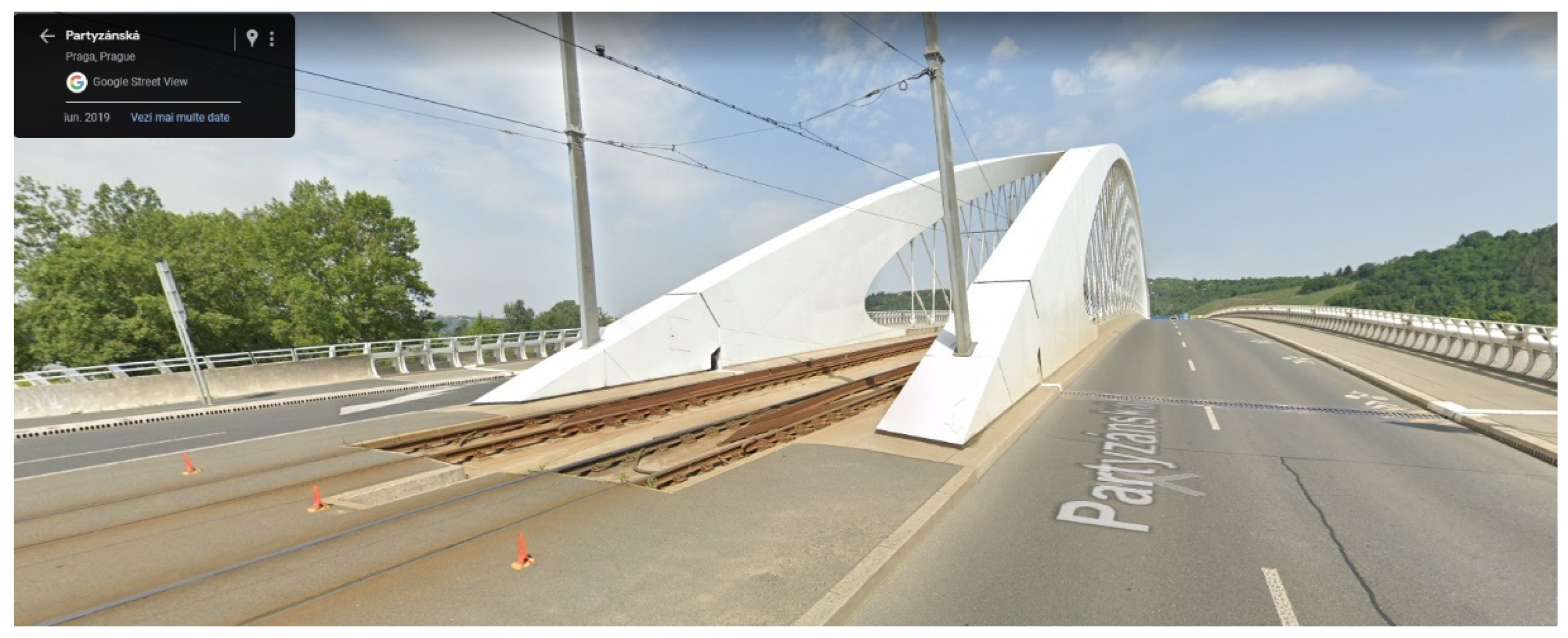
Figure 12.
The Sixth Street Viaduct in Los Angeles. Photo © Gary Leonard, 2022.
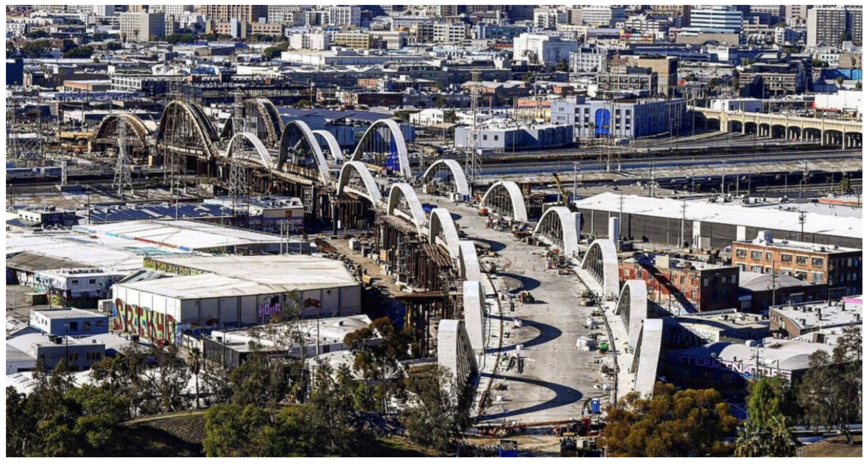
Figure 13.
The Brandanger Bridge in Norway: (a) Cross-section [23]; (b) Side view of the bridge.
Figure 13.
The Brandanger Bridge in Norway: (a) Cross-section [23]; (b) Side view of the bridge.
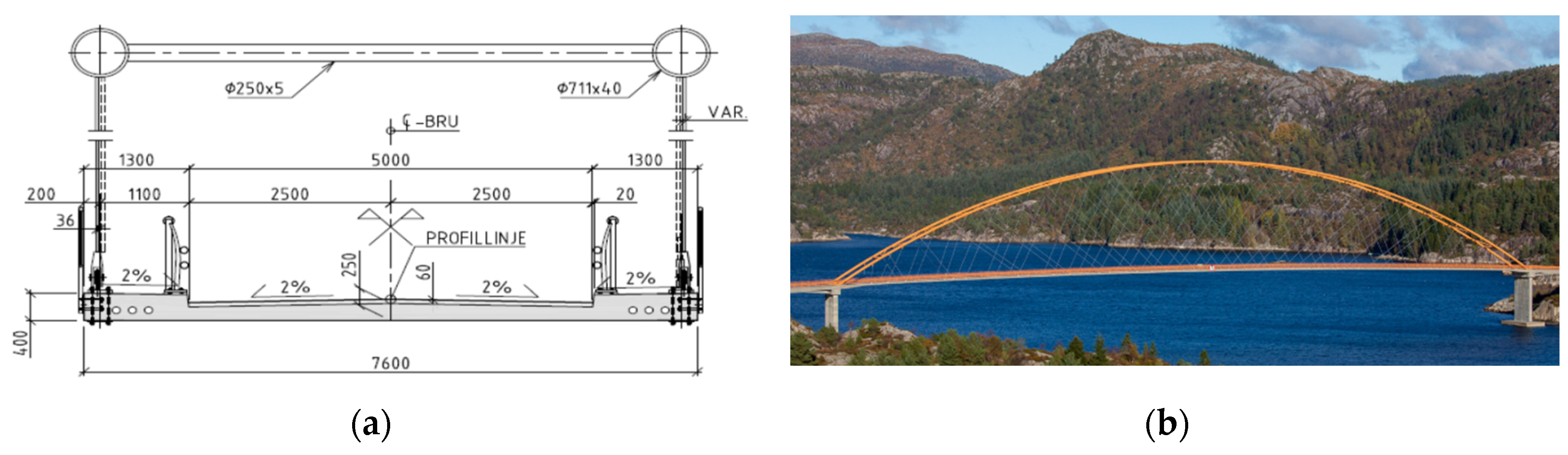
Figure 14.
Hanger crossing device in the form of a needle eye [28].
Figure 14.
Hanger crossing device in the form of a needle eye [28].
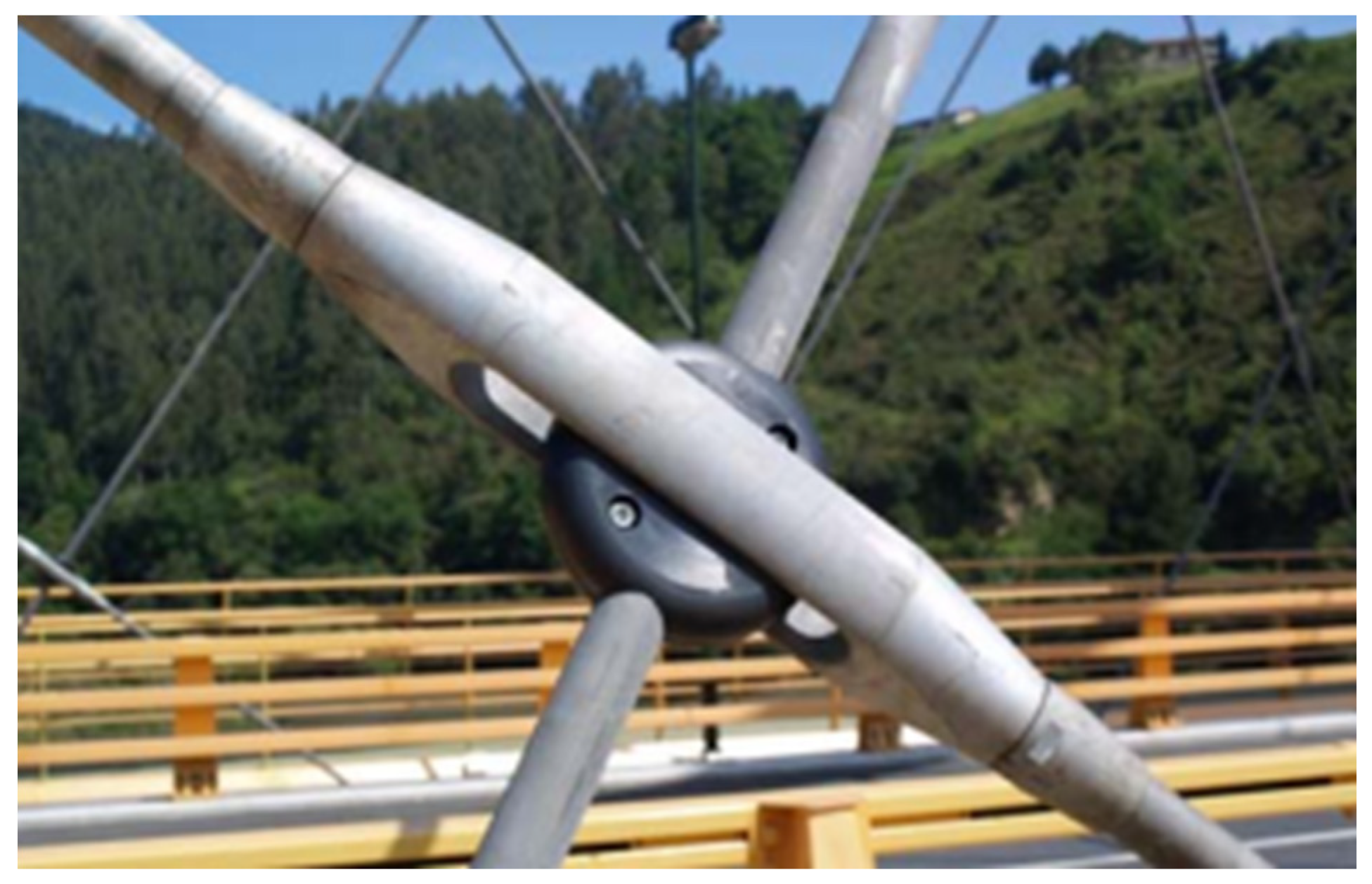
Figure 15.
Stuttgart Stadtbahn Bridge.
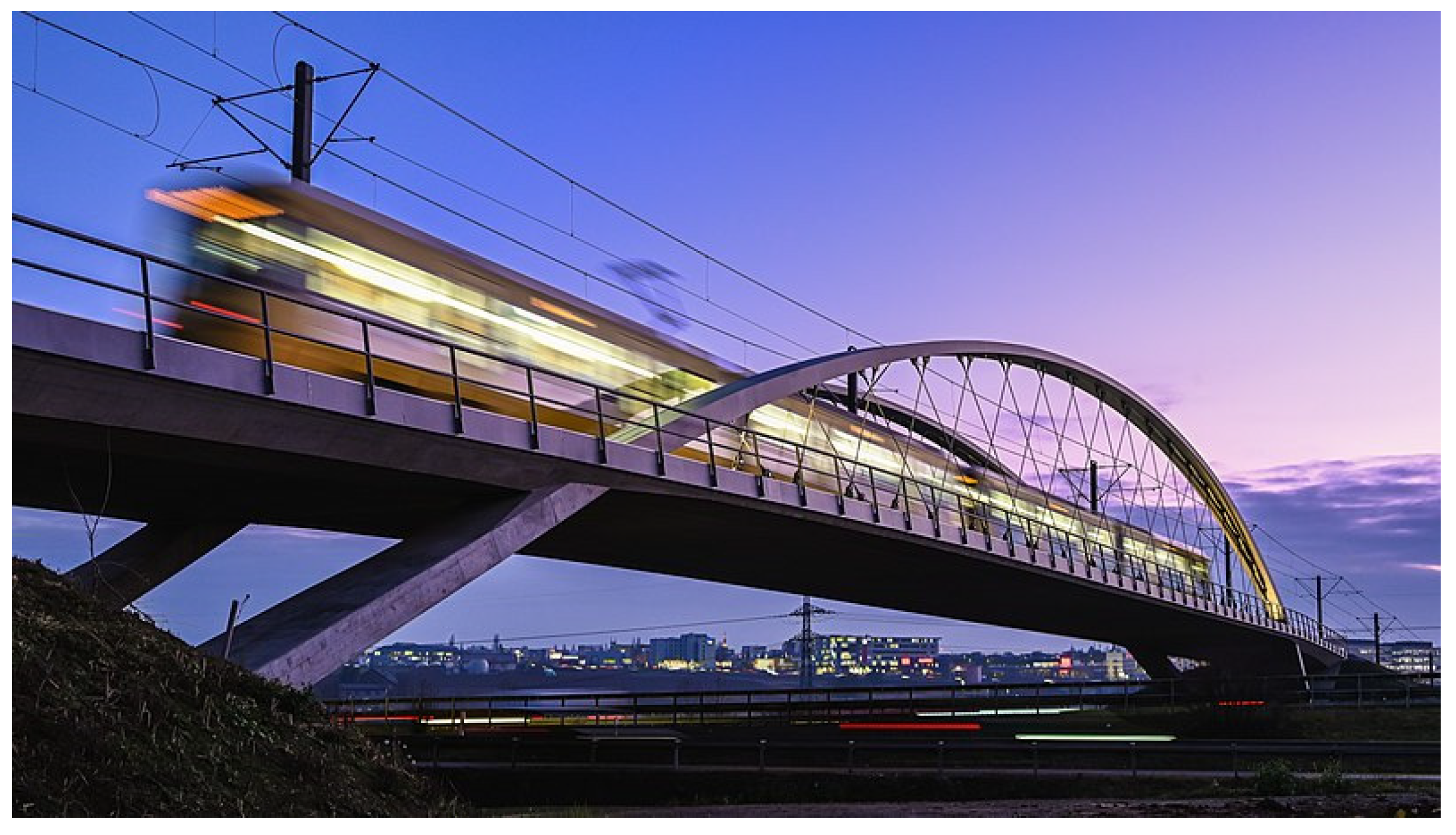
Figure 16.
Cross-section of the Zezelj NAB in Novi-Sad adross the Danube [37].
Figure 16.
Cross-section of the Zezelj NAB in Novi-Sad adross the Danube [37].
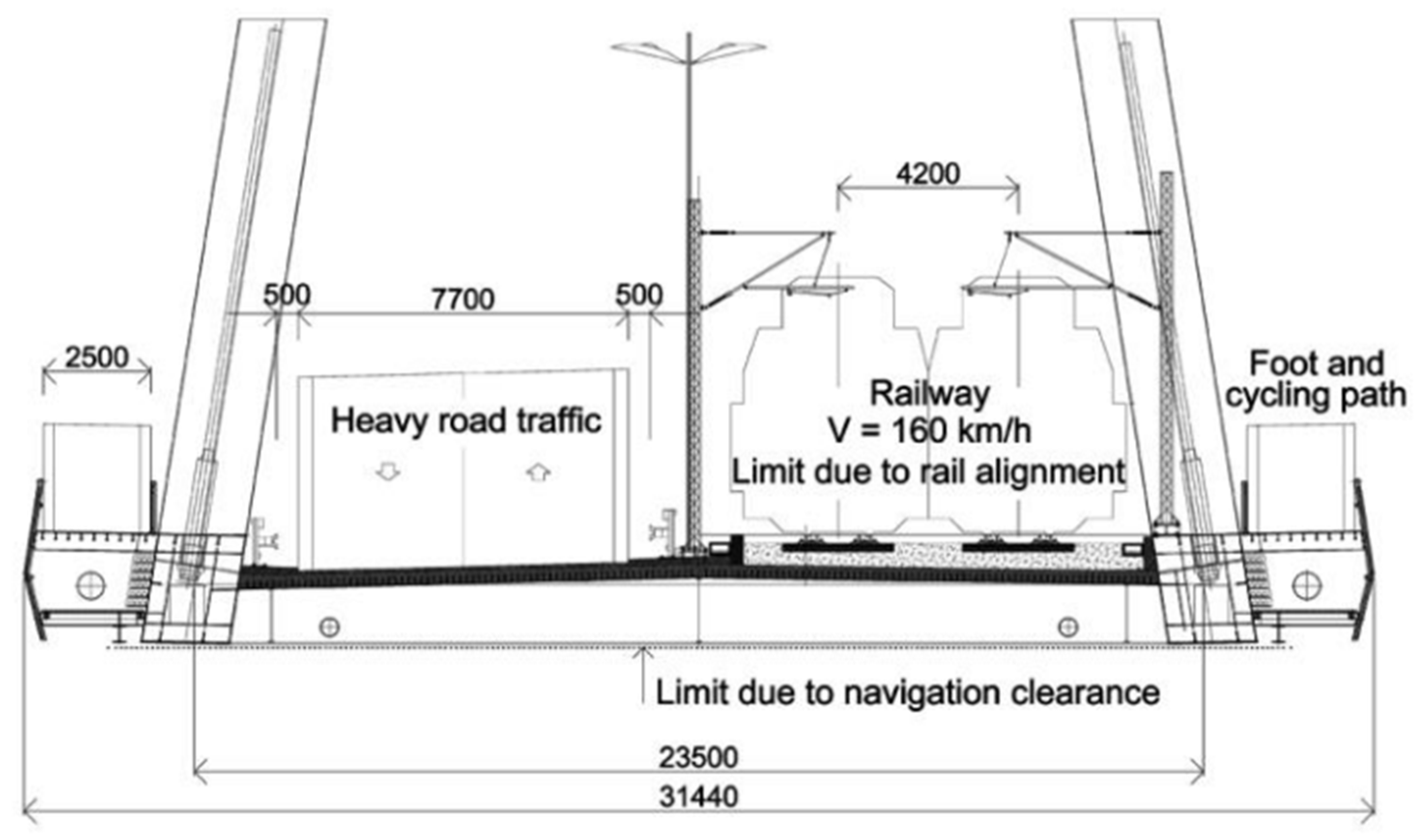
Figure 17.
The Steien Bridge: (a) Side view of the bridge; (b) Cross-section [40].
Figure 17.
The Steien Bridge: (a) Side view of the bridge; (b) Cross-section [40].
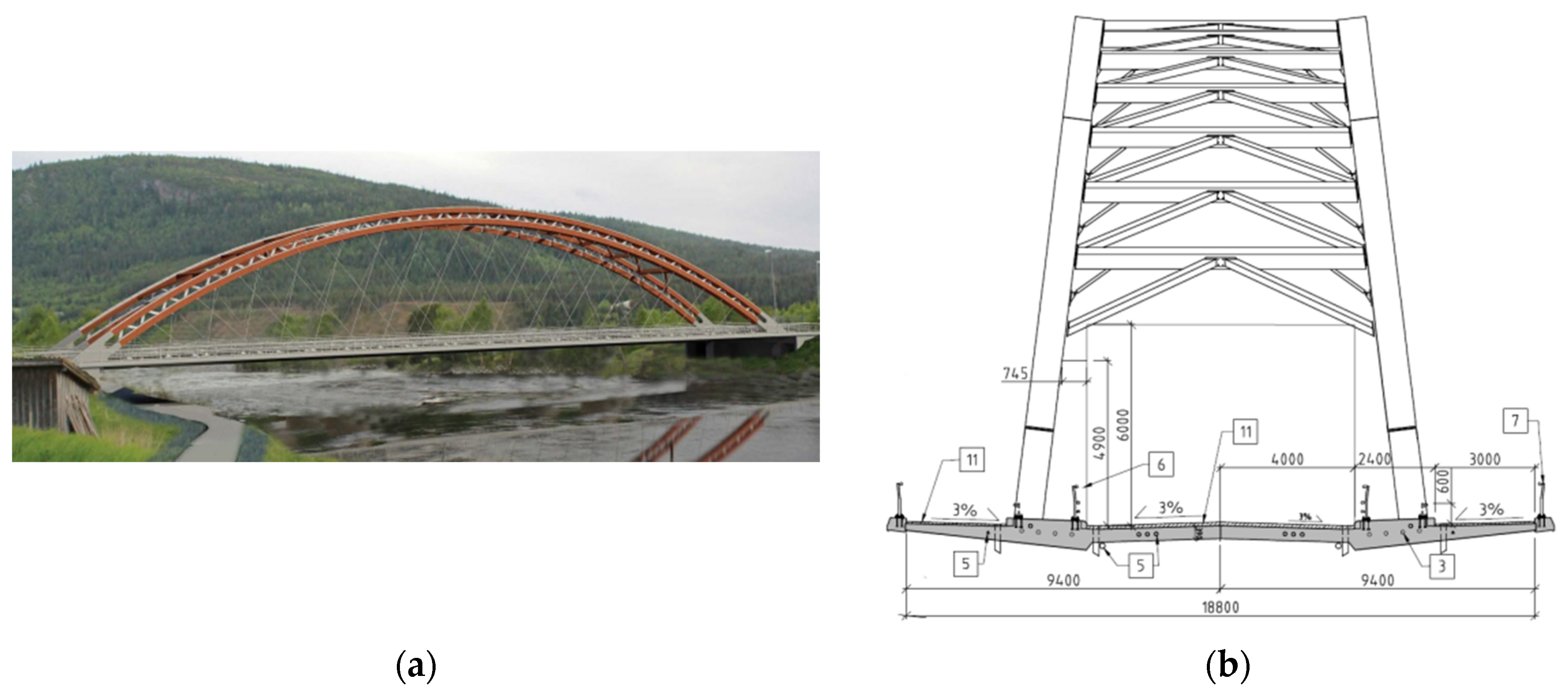
Figure 18.
NAB in numbers: (a) Continent distribution; (b) Opening year; (c) Number of structures in different systems; (d) Type of bridge.
Figure 18.
NAB in numbers: (a) Continent distribution; (b) Opening year; (c) Number of structures in different systems; (d) Type of bridge.
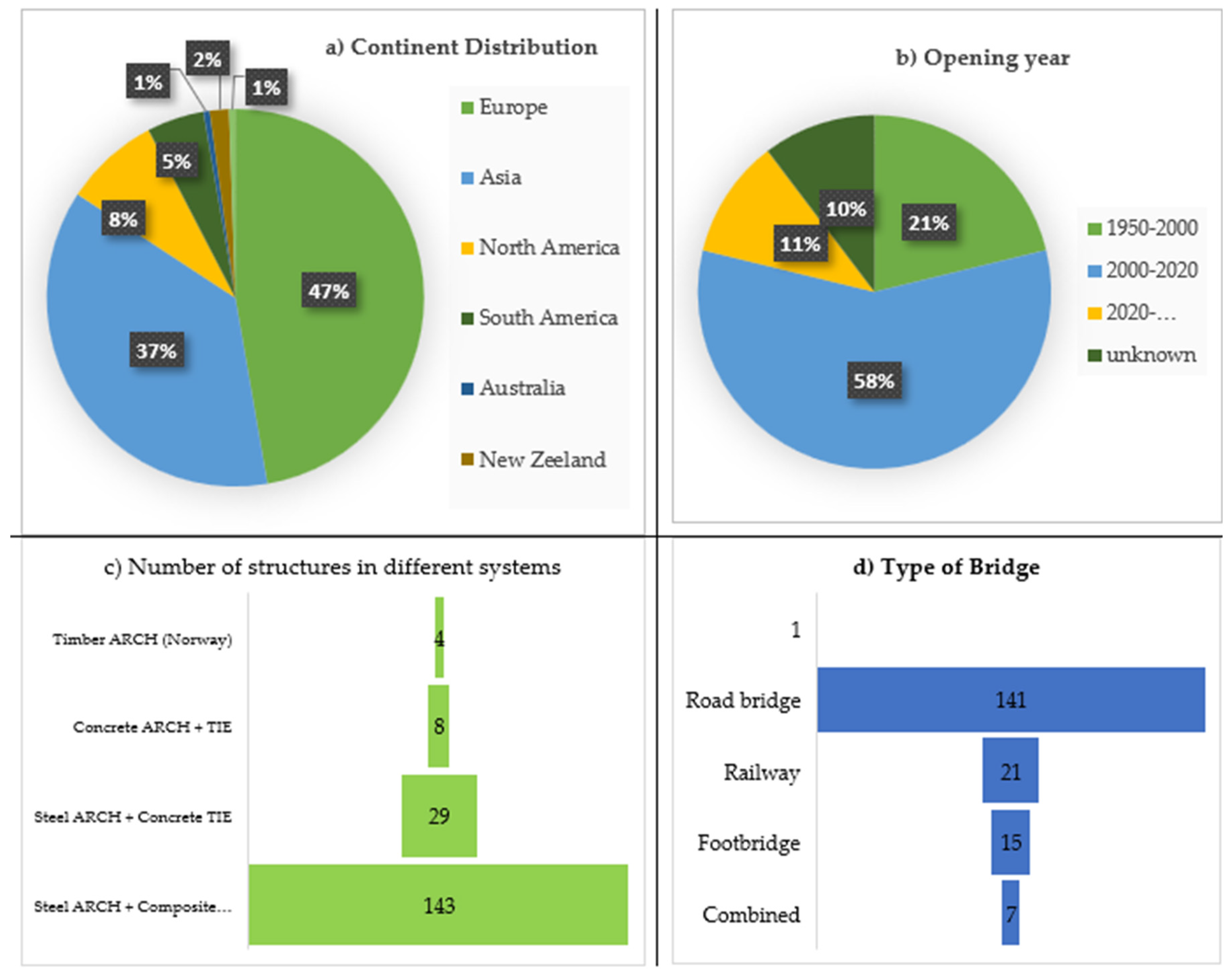
Figure 19.
Network Arch Bridges with no upper wind bracing.
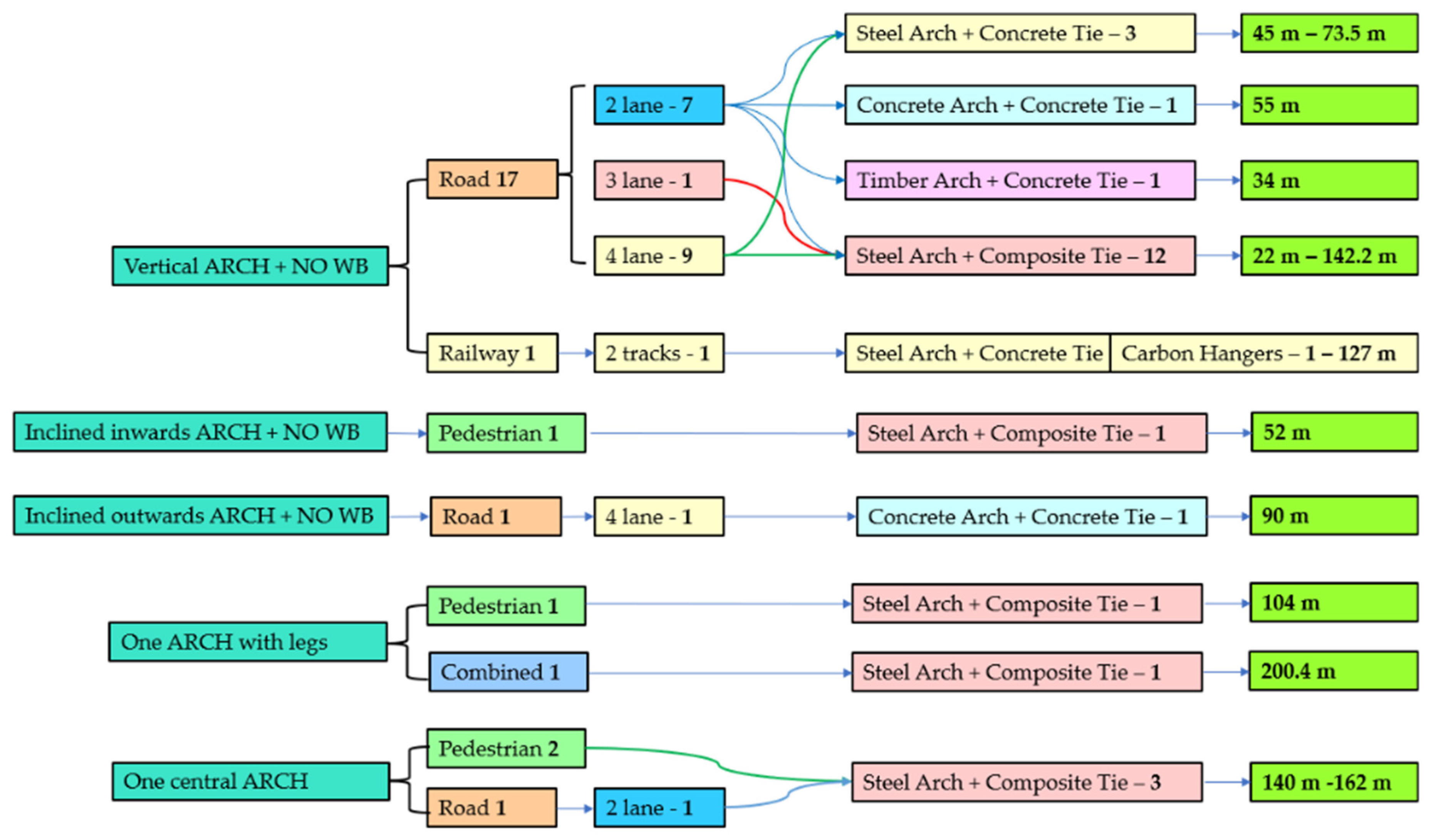
Figure 20.
Pedestrian Network Arch Bridges.
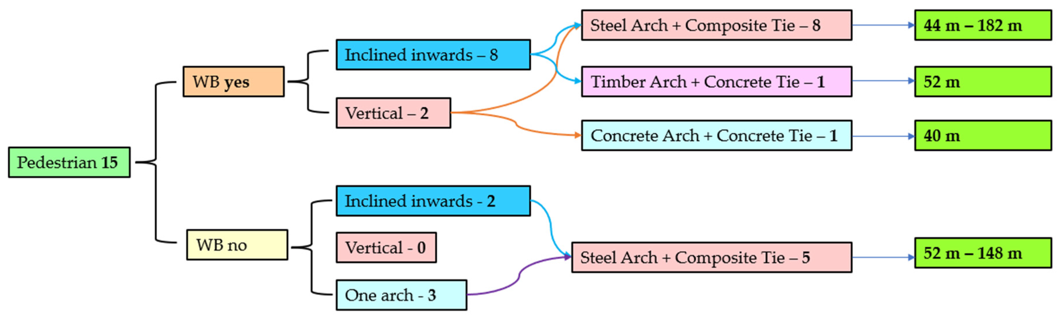

Table 1.
Timber Network Arches.
| Bridge Name | Location | Opening | Type | Span [m] | Arch | Tie | Lateral buckling |
| Steien Bridge | Alvdal, Norway | 2016 | Road | 88.2 | Glulam, truss box | concrete | Arch Inclined inwards, WB |
| Våla Bridge | Ringube, Norway | 2020 | Pedestrian | 52 | Glulam, box | Concrete | Arch Inclined inwards, WB |
| Hellefossbrua | Etnedal, Norway | 2019 | Road | 70 | Glulam, box | Concrete | Arch Inclined inwards, WB |
| Prestmyra bru | Elverum, Norway | 2018 | Road | 34 | Glulam, box | Concrete | WB |
Table 2.
Concrete Network Arch Bridges.
| Bridge Name | Location | Opening | Type | Traffic | Span [m] | Arch+Tie | Arches+WB |
| Steflinger River Bridge | Steflinger, Germany | 2015 | Road | 2 lane | 55 | Concrete | Vertical, no WB |
| Nervión Bridge | Bilbao, Spain | 2017 | Railway | 2 tracks | 80 | Concrete | Inclined inwards, WB |
| Bijuli Bazar Bridge | Kathmandu, Nepal | 2019 | Road | 2 lane | 52 | Concrete | Vertical, WB |
| Bijuli Bazar Bridge | Kathmandu, Nepal | 2019 | Road | 2 lane | 52 | Concrete | Vertical, WB |
| Rayar Bazar Bridge | Dacca, Bangladesh | 2015 | Pedestrian | Pedestrian | 40 | Concrete | Vertical, WB |
| Tsukani Bridge | Mitsuqi Dam, Japan | NA | Road | 2 lane | 151 | Concrete | Vertical, WB |
| W 7th Street Bridge | Dallas, USA | 2013 | Road | 2 lane | 6x50 | Concrete | Vertical, WB |
| Bent Bridge | San Josa, USA | 2011 | Pedestrian | Pedestrian | 82.3 | Concrete | Vertical, WB |
| Sixth Street Viaduct | Los Angeles, USA | 2022 | Road | 4 lane | 10x90 | Concrete | Inclined outwards, no WB |
Disclaimer/Publisher’s Note: The statements, opinions and data contained in all publications are solely those of the individual author(s) and contributor(s) and not of MDPI and/or the editor(s). MDPI and/or the editor(s) disclaim responsibility for any injury to people or property resulting from any ideas, methods, instructions or products referred to in the content. |
© 2023 by the authors. Licensee MDPI, Basel, Switzerland. This article is an open access article distributed under the terms and conditions of the Creative Commons Attribution (CC BY) license (http://creativecommons.org/licenses/by/4.0/).
Copyright: This open access article is published under a Creative Commons CC BY 4.0 license, which permit the free download, distribution, and reuse, provided that the author and preprint are cited in any reuse.


