Submitted:
21 August 2023
Posted:
29 August 2023
You are already at the latest version
Abstract
The surging electricity demand driven by a growing global population, coupled with the increasing electrification of industries, transportation, and power-intensive appliances, poses a substantial challenge to electricity systems worldwide. This challenge is further compounded by the pressing issue of climate change. To address climate change and mitigate the environmental consequences of fossil fuel use, renewable energy sources are expected to play a pivotal role. However, certain renewable sources, such as wind and solar, exhibit stochastic behavior, resulting in unpredictable power output and significant fluctuations. This intermittency presents a challenge in maintaining a stable and reliable power supply. To overcome this challenge and ensure a balanced electricity grid, the strategic deployment of energy storage devices throughout the power system becomes critically important. Energy storage technologies play a vital role in mitigating the mismatch between renewable power generation and consumption. Additionally, they enable the storage of surplus energy generated from renewable sources during periods of high production for later use during periods of low or no generation. Each technology possesses unique characteristics and applications, providing flexibility and diversity in energy storage solutions. This work provides an overview of different energy storage technologies and explores their role in establishing a sustainable power system.
Keywords:
LV
; MV
; Energy Storage System
0. Introduction
The structure of the electrical power system is currently experiencing a substantial change, shifting towards renewable energy resources as a primary source of power generation. This transition is driven by several factors, including the growing global demand for electricity, the limitations faced by developing countries in building traditional power plants and distribution networks, the inadequate power generation capacity in some industrialized nations, and the concerns about climate change and greenhouse gas emissions [1]. In this evolving landscape, renewable energy sources are progressively emerging as essential elements within forthcoming power generation systems. These technologies cover a wide spectrum, including but not limited to wind turbines, solar photovoltaic setups, solar thermal installations, biomass power facilities, fuel cells, gas micro-turbines, hydropower turbines, micro-turbines for combined heat and power (CHP), and also hybrid power systems [2,3]. These environmentally friendly and sustainable alternatives are gradually replacing fossil fuels, paving the way for a more resilient and cleaner energy future.
Incorporating renewable energy sources (RESs) into the power grid brings about various benefits, but their variable and intermittent nature can also pose challenges. Fluctuations in wind, lightning strikes, sudden load changes, or line faults can result in temporary drops in system voltage [4]. To overcome these issues, energy storage has been recognized as an effective way to address the stochastic characteristics and rapid shortfalls of RESs.By offering the capability to store surplus energy when generation is high and discharge it when generation is low or variable, energy storage systems mitigate the impact of load loss and decrease the necessity of deploying extra generation plants. This capability enhances grid stability and ensures a more reliable and sustainable electricity supply [5,6]. A further concern arises when integrating RESs into remote areas with weak grids, as this may result in undesirable voltage alterations due to power variations. Addressing the challenges posed by the intermittent nature of renewable energy sources often involves costly upgrades to transmission power lines, which can be financially prohibitive. Nevertheless, a feasible and economically viable option involves incorporating energy storage systems to even out power levels and regulate voltage at distant connection points. This approach enables the effective utilization of energy, mitigating the sporadic attributes of renewable energy. As a result, grid stability remains intact, bolstering the overall reliability and efficiency of the system. The application of energy storage systems offers a practical and cost-effective approach to enhancing the smooth incorporation of renewable sources into the existing power infrastructure. The escalating need for energy storage systems is propelled by diverse factors that are molding the present scenario [7]. These factors include the increasing use of stochastic generation from renewable sources, the strain on transmission infrastructure due to lagging development of new power lines, the rise of micro-grids within distributed grid architecture, as well as the increased demand for security and dependability in the provision of power [8] . Yet, several hurdles persist in the realm of effectively incorporating these nascent energy storage technologies into the electricity grid. These challenges span operational, technical, and market facets, underscoring the need for comprehensive research, experimentation, and standardization to tackle these concerns. The progression of energy conversion units (ECUs), spanning renewable energies, as well as the assimilation of energy storage systems (ESSs) within developed nations, should be undertaken with careful consideration of the existing electrical supply infrastructure. Consequently, a comprehensive and multifaceted challenge of integrating energy storage systems optimally will arise, aiming to achieve efficient and effective integration within the current electric power system. When power plants used to shut down over night in the early 20th century, stationary Electrical Energy Storage (EES) was first developed. During that period, lead-acid accumulators played a crucial role in powering remaining loads within direct current networks [9,10]. However, it was not until 1929 that the first energy storage central station, known as Pumped Hydroelectric Storage (PHS), was established. Utility companies gradually recognized the significance of energy storage in enhancing network flexibility, which led to the establishment of the PHS system [11,12].As time passed, the power supply sector’s emphasis transitioned towards attaining economies of scale by means of substantial central generating stations and expansive transmission and distribution networks. Consequently, the enthusiasm for storage systems waned until the recent past. However, in more contemporary times, there has been a renewed surge of interest in energy storage systems. The importance of storage technology in promoting grid stability and easing the assimilation of renewable energy sources has been acknowledged by the power sector. In particular, Pumped Hydroelectric Storage (PHS) systems have gained prominence once again due to their ability to provide large-scale, flexible, and reliable storage capacity.By the year 2005, more than 200 PHS systems had been implemented, contributing to an impressive 100 GW of generation capacity. This resurgence underscores the critical role that energy storage plays in modern power systems and its potential to solve the difficulties brought on by the increased use of renewable energy and the requirement for a more adaptable and durable grid infrastructure. [11,13]. A decrease in investment in significant PHS facilities was also brought on by regulatory pressures and environmental issues. Due to various factors, there has recently been an increase in interest in the practical use of EES systems. These encompass alterations to the international utility regulatory landscape, an amplified dependence on electricity across industrial, commercial, and residential domains, issues pertaining to power reliability and provision, and a substantial rise in the utilization of renewable energy as a primary electricity source, and more stringent environmental regulations [14,15,16]. Moreover, the rapid advancement of technology in emerging EES systems,due to projected cost reductions, their practical applications are expected to become significantly appealing in a matter of a few years.consequently, the practical use of energy storage systems is experiencing a revival, driven by the convergence of these factors and the potential for significant technological advancements in the near future. This article seeks to provide a succinct summary of the various Electrical Energy Storage Systems (EESS) technologies that are currently in advanced development. These technologies include: Pumped Hydroelectric Storage (PHS) [13,17,18], Compressed Air Energy Storage system (CAES) [19,20], Batteries [21,22]and [23],Flow Batteries [10,14,16,24],Fuel Cells [24,25],Solar Fuel [10,16],Superconducting Magnetic Energy Storage system (SMES) [26,27],Flywheels [28,29,30] ,Capacitors and Supercapacitors [10,29] and Thermal Energy Storage system (TES) [31,32].Some of these technologies are already accessible and in use, while others are still under development. This paper provides a thorough analysis of different energy storage methods and investigates their significance and technical attributes in building a sustainable power system.
1. Technologies for Electrical Energy Storage Systems
1.1. Electrical Energy Storage (EES)Definition
The act of converting electrical energy from a power network into a form that may be stored and later converted back into electrical energy as needed is known as electrical energy storage (EES) [8,14,33]. This approach enables the generation of power from intermittent energy sources or inexpensive, low-demand energy sources, which can then be utilized during periods of heightened demand, elevated generation expenses, or when alternative generation methods are unavailable. [15,33,34,35] (Figure 1). Applications for EES are numerous and include portable devices, automobiles, and stationary energy resources [9,10,33,36].The primary focus of this work is stationary Electrical Energy Storage (EES) systems used in a variety of applications, such as electricity generation, distribution, and transmission systems, decentralized energy resources, the incorporation of renewable energy, and utilization within regional industrial and commercial sectors.
Stationary EES systems play a pivotal role in bolstering the stability, dependability, and effectiveness of electricity grids. They facilitate the seamless assimilation of renewable energy sources and enhance overall energy management. These systems achieve this by storing surplus electricity during periods of diminished demand or heightened renewable energy generation, EES systems can lessen reliance on conventional fossil fuel-based power plants, balance supply and demand, and offset the intermittent problems brought on by renewable energy sources. Throughout this document, we will explore various aspects of EES technologies, including their classifications, applications, technological specifications, advancements in research and development, and deployment status, with a specific focus on their use in stationary applications within the power sector.
1.2. Principal Role of Energy Storage Systems
The configuration and functioning of the electric power system might experience profound transformations as a result of developments that significantly lower the cost of electricity storage devices [7]. These breakthroughs could address peak load challenges, enhance electrical stability, and eliminate power quality disturbances. The flexible and multipurpose role that energy storage plays in the electric power system makes it possible to handle the available power supplies more effectively. Energy Storage Systems (ESS) serve a critical role in maintaining real-time balance between production and consumption, which enhances grid management and dependability when used in conjunction with power generation systems that convert renewable energy sources [38,39]. Furthermore, Energy Storage Systems (ESS) streamline the incorporation of renewable resources into the energy framework. They accelerate the rate at which these resources are adopted and enhance the energy quality by effectively controlling frequency and voltage.Storage alternatives can be deployed across various points, spanning power plants, transmission systems, distribution networks, and even certain appliances and gadgets on the meter’s customer side [7,40]. These diverse applications of energy storage contribute to more efficient energy utilization, grid optimization, and enhanced reliability throughout the electric power system.
The utilization of Energy Storage Systems (ESS) offers significant advantages in reducing peak loads and eliminating the need for additional thermal power plants that operate only during peak periods. This approach enables more efficient utilization of power plants by allowing them to function continuously, resulting in a substantial decrease in greenhouse gas (GHG) emissions [41]. The incorporation of energy storage systems with state-of-the-art power electronics, acting as the intermediary between the electrical grid and the storage systems, plays a significant technological role, and offers various cost advantages. The following sections provide an overview of few of these advantages. Figure 2 also demonstrates how the power supply chain is changing due to the incorporation of energy storage systems (ESS). In Section 3 below, more information about various uses of energy storage systems will be given.
2. Energy Storage Systems Applications and Technical Advantages
Figure 3 shows the five essential links that make up the electricity value chain:the source of the fuel or energy, the generation, the transmission, the distribution, and the consumer-oriented energy provision. With their capacity to provide electricity precisely when and where it’s needed, Energy Storage Systems (ESS) are poised to serve as the "sixth connection," uniting current segments and cultivating a more agile market environment [7]. Figure 3 and Figure 4 depict the incorporation of stored energy into the generation-grid system [28]. EES has a wide range of essential application that can be applied to many different scales and fields.These applications range from larger generation and transmission systems to those that only focus on growing into the distribution network and even going "beyond the meter" to customer/end-user locations [9]. Numerous essential applications of EES have been identified and summarized in previous studies [7,28,29,42]. These applications encompass various aspects of the electricity system and include:
- Peak load management and demand response programs.
- Making use of renewable energy sources and reducing their erratic output.
- Offering additional services like voltage stabilization and frequency regulation.
- Microgrids and local energy systems.
- Grid stability and reliability enhancement.
- Backup power and uninterruptible power supply (UPS).
- Management of energy based on time-of-use and energy arbitrage.
- Charging infrastructure for electric vehicles and services for vehicle-to-grid (V2G) interactions.
- Power quality improvement and mitigation of voltage sags and swells.
- Electrification of remote and off-grid areas.
These applications demonstrate the diverse and significant potential of EES across the electricity value chain, revolutionizing the way energy is generated, delivered, and consumed.
2.1. Generation
- Commodity Storage: In this use, excess energy produced during off-peak times, such the night, is stored for use during the day’s high demand hours.By arbitrating the output price between these two periods, it enables more efficient load factor control for the generation, transmission, and distribution networks, leading to cost savings [29].
- Contingency Service: Contingency reserves are a form of power capacity that can be deployed to meet customer demand in the event of a power facility going offline. Spinning reserves are immediately available, while long-term and non-spinning reserves can be used in as little as 10 minutes.Spinning reserve denotes the generation capacity available to produce active power within a specific timeframe, which hasn’t been allocated for energy production yet. [44].
- Area Control: This application involves preventing unplanned power transfers between different utility systems, maintaining the stability and reliability of the overall grid.
- Grid Frequency Support: In order to prevent sudden imbalances between load and generation and to keep the system’s standard 60Hz/50Hz (cycles per second) In both standard and non-standard grid arrangements, the frequency is in a condition of equilibrium, actual power must be supplied to the electrical distribution grid. Electrical equipment owned by consumers as well as generators may be harmed by abrupt and significant changes in electrical load.
- Black-Start:Black-start capability is the ability of an entity to autonomously commence startup procedures,initiate the transmission system, and aid in the commencement and synchronization of other facilities with the grid. This capability is crucial in restoring power to the grid after a complete blackout or system-wide shut down.
These applications demonstrate the versatility of energy storage systems in supporting various grid operations and services, including load management, grid stability, frequency control, and system restoration.
2.2. Distribution and transmission system
- System Stability: This refers to the capability of maintaining synchronous operation among all system components on a transmission line, preventing a collapse or disruption of the entire power system.
- Angular Stability of the Grid: In order to maintain stable and controlled grid functioning, power oscillations brought on by sudden occurrences are reduced through the addition and consumption of active power.
- Grid Voltage Support: In order to keep voltage levels across all power lines within a reasonable range, the electrical distribution system needs to be powered. By achieving a balance between the quantity of actual energy and the level of reactive power generated by generators, the voltage profile of the grid is controlled and stabilized. [45].
- Deferral of Assets: This application centers on postponing the necessity for extra transmission infrastructure by complementing the existing transmission setup. Energy storage systems can potentially increase the effectiveness of current transmission facilities, saving money that would otherwise be needed for capital investments in the construction of new infrastructure that might go unutilized for extended periods of time [44].
These applications contribute to the overall stability, reliability, and efficiency of the power system by addressing issues related to grid stability, power oscillations, voltage regulation, and optimizing infrastructure investments.
2.3. Electrical Energy Management
- Energy Management (Load Leveling / Peak Shaving): Load leveling involves the reorganization of specific loads to reduce electricity demand or store surplus energy when demand is low, subsequently harnessing it during hours of high demand. Peak shaving, on the other hand, comprises cutting back on electricity use during busy times or switching to off-peak hours. Customers can control their energy consumption using these methods, especially to lower time-of-use (demand) charges.
- Unbalanced Load Compensation: Employing four-wire inverters and introducing or absorbing power independently in each phase to supply energy to unbalanced loads enables the correction of unbalanced load conditions. This approach helps maintain balanced operation and supply adequate power to all phases.
- Enhancement of Power Quality: Power quality pertains to variations in voltage, current, and waveform characteristics. Harmonics, power factor, transients, flicker, voltage sags and swells, and voltage spikes can all impact power quality. Distributed Energy Storage Systems (DESS) can adeptly tackle these issues, furnishing customers with dependable electrical service without introducing additional fluctuations or disturbances to the electrical waveform [44].
- Power Reliability: Power reliability is measured by the percentage or ratio of interruptions in the delivery of electric power, which may include instances where power exceeds the threshold, not just complete power outages. DESS can enhance power reliability by providing uninterrupted power supply (UPS) capabilities to "ride-through" power disruptions. When coupled with energy management storage, it enables remote power operations and ensures a reliable power supply [43]. These applications demonstrate how energy storage systems contribute to effective energy management, enhance power quality, and improve the reliability of electrical power supply. They enable load balancing, compensate for unbalanced loads, mitigate power quality issues, and provide backup power during disruptions, thereby ensuring a stable and uninterrupted power supply for consumers.
2.4. Financial benefits of EESS in Power Systems
In [46], a thorough examination of the advantages of energy storage is provided, highlighting the following key points:
- Reducing Costs or Boosting Revenue via Bulk Energy Arbitrage: Energy storage makes it possible to purchase electricity at a low cost when there is a drop in demand, allowing for later use or sale when electricity prices are high. This practice results in either cost reductions or increased revenue.
- Cost Avoidance or Revenue Enhancement through Central Generation Capacity: Energy storage can counteract the requirement for new generation capacity by supplying extra power during peak demand intervals. This effectively circumvents the expenses linked to constructing new generation facilities or leasing capacity from the market for wholesale electricity.
- A reduction in costs or an increase in revenue from supplementary services: Energy storage systems have the capability to offer ancillary services like spinning reserve and load following, contributing to the preservation of stability and dependability within the regional grid.
- Cost Avoidance or Revenue Enhancement through Transmission Access/Congestion Mitigation: Energy storage has the potential to improve the efficiency of the Transmission and Distribution (T&D) system by augmenting energy transfer capabilities and stabilizing voltage levels, thereby avoiding transmission access or congestion charges.
- Reduced Demand Charges: Energy storage has the capacity to diminish an end-user’s dependency on the grid when peak demand occurs, resulting in decreased demand charges on their electricity invoices.
- Diminished Financial Impact from Reliability Issues: Energy storage alleviates financial losses linked to power interruptions, especially for commercial and industrial clients that encounter noteworthy economic setbacks during periods of downtime.
- Diminished Financial Impact from Power Quality Issues: Energy storage curtails financial losses arising from power quality irregularities that disrupt loads or damage electrical equipment. By using energy storage, the negative effects of such anomalies can be avoided.
- Enhanced Revenue from Renewable Energy Sources: Energy storage facilitates the temporal adjustment of energy produced by renewable sources. Surplus energy can be stored when demand is low and subsequently utilized when demand aligns with elevated renewable generation output.
These functionalities highlight the significant impact that energy storage, in conjunction with power electronics, will have on future electrical supply systems. Therefore, to enable quick integration processes, all planning and implementation methods should take into account the operational and real-time control capabilities of decentralized energy resources (DERs) and energy storage systems (ESS).
3. Energy storage system economic and technical characteristics
The selection criteria for electrical storage systems are typically based on the following key characteristics [47]:
3.1. Energy Capacity :
This pertains to the overall energy capacity of the storage system, encompassing the energy it can store and provide upon demand. It plays a crucial role in assessing a system’s ability to fulfill the energy requirements of a specific application.
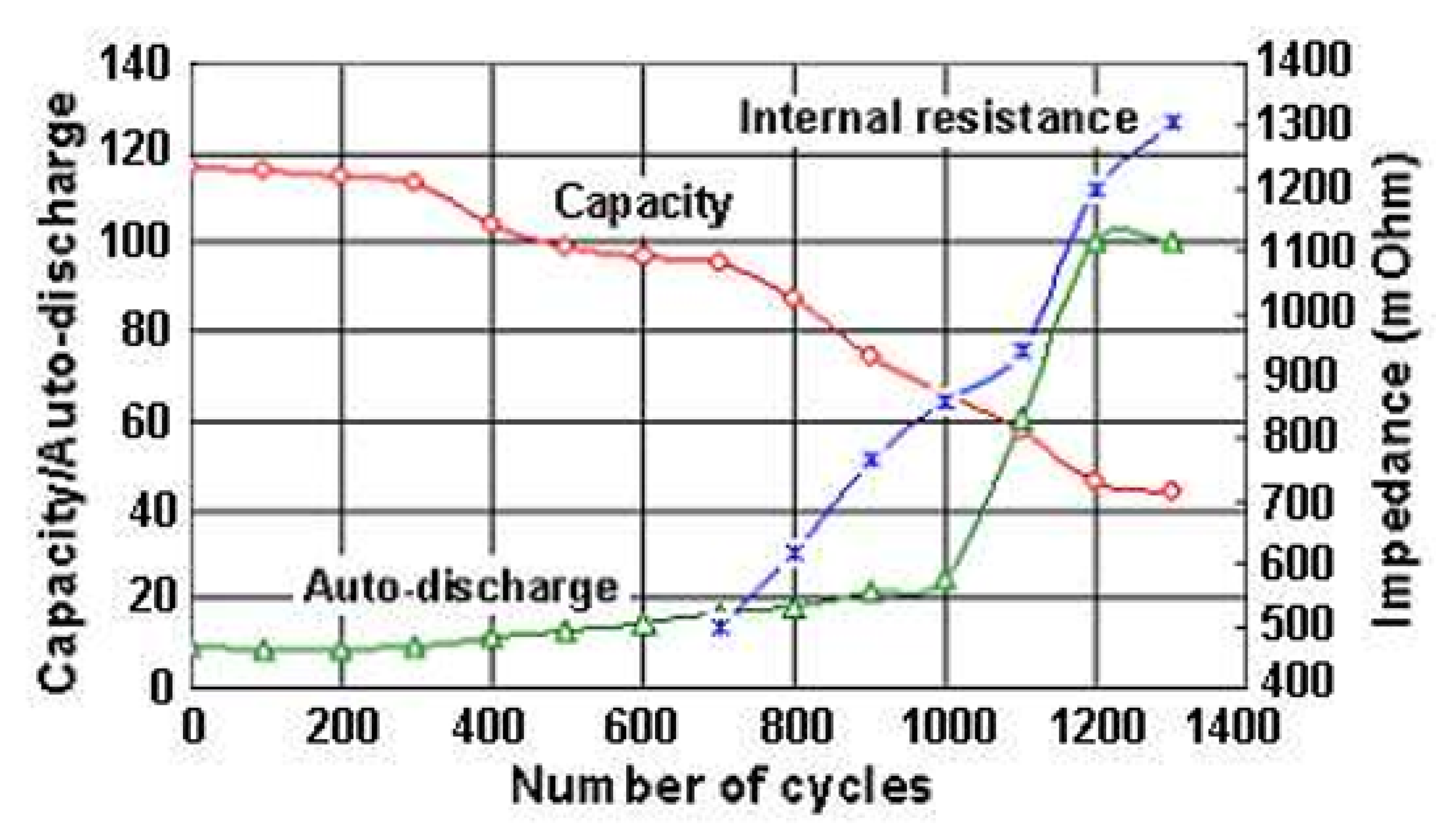
Figure 5.
Alteration of energy capacity, self-discharge with the number of cycles [48].
Figure 5.
Alteration of energy capacity, self-discharge with the number of cycles [48].
3.2. Power Capacity :
Power capacity signifies the highest rate at which the storage system can dispense or intake power. This capacity governs the system’s capability to manage abrupt shifts in demand or supply and impacts its appropriateness for tasks necessitating substantial power output or swift response durations.
The capability of storage systems to provide high-power output for short duration, commonly known as the "emergency" rating, can be useful in exceptional instances that require immediate and substantial power supply. However, it’s important to note that discharging at the emergency rate may result in reduced storage efficiency compared to the nominal discharge rate and increase the risk of equipment damage. Essentially, storage systems with emergency power capability can meet the regular power requirements, such as peak demand reduction, while also offering additional power for infrequent urgent needs lasting for a few to several minutes [49].
3.3. Efficiency
Efficiency measures how well the energy can be converted and stored by the storage mechanism. This ratio represents the energy output relative to the energy input, showcasing the system’s effectiveness in minimizing energy losses during charge and discharge cycles. Note that,every energy conversion and transfer process involves losses, and energy storage systems are not exempt from this. The round-trip efficiency, or simply efficiency, of a storage system denotes the proportion of energy output compared to energy input. However, this definition can be overly simplified if it relies on a solitary operational point, potentially failing to accurately depict the system’s performance for a particular application. To establish efficiency, It is essential to consider one or more realistic cycles that align with the intended use. The instantaneous power plays a significant role in determining efficiency (as shown in Figure 6). Thus, an optimal power transfer sequence should mitigate losses during energy transfer and self-discharge. This aspect of conserving energy is particularly critical for applications such as daily network load leveling. Typical efficiency values diverge among various storage technologies. Conventional electrochemical batteries generally range from 60% to 75%, while advanced electrochemical batteries achieve efficiencies of 75% to 85%. Compressed Air Energy Storage (CAES) systems typically exhibit efficiencies between 73% and 80%, while pumped hydro storage systems operate in the range of 75% to 78%. Flywheel storage boasts efficiency rates of 80% to 90%, whereas Superconducting Magnetic Energy Storage (SMES) systems and capacitors reach efficiencies of 95% [49,50].
3.4. Time Response
Response time refers to how quickly a storage system may modify its power output in response to changes in supply or demand. Systems with faster response times are better suited for applications requiring rapid power modulation or frequency regulation. The response time of a storage system refers to the duration it takes to transition from a state of no discharge to full discharge. This characteristic is influenced by the specific application of the storage system. In scenarios where storage is utilized to replace transmission and distribution (T&D) capacity, it must exhibit a rapid response. This is because T&D equipment, such as wires and transformers, reacts almost instantaneously to changes in demand [47].
On the other hand, when storage is used as a substitute for generation capacity, the response time requirement is less immediate. This is because generation sources typically respond relatively slowly to demand fluctuations.For instance, it could take several seconds to many minutes for engines and combustion turbines to reach their full power, whereas coal and nuclear-powered generation could take hours to respond. In contrast, most storage systems possess response times of a few seconds or less, enabling them to effectively cater to diverse applications. Although Compressed Air Energy Storage (CAES) and pumped hydroelectric storage display slightly slower response times, they still manage to react swiftly enough to fulfill critical requirements.
3.5. Life Cycle
The life cycle is the maximum number of charge-discharge cycles that a storage system can withstand before experiencing a noticeable performance decline. It is a vital consideration for long-term durability and cost-effectiveness, as systems with longer cycle lives require less frequent replacement. Lifetime or durability of a storage unit refers to its ability to consistently release the intended energy level following every recharge, is measured by the highest number of cycles N, where each cycle consists of a charge and a discharge. [50] . Over time, Every charge-discharge cycle result in the degradation of all electrical storage systems as a result of wear or fatigue. This degradation is the predominant contributor to aging and extends beyond thermal degradation. The pace of deterioration hinges on variables like storage technology, operating conditions, and other factors, with a specific emphasis on electrochemical batteries.
In some storage technologies, particularly batteries, the degree of discharge also affects how long the storage medium lasts.A shallow discharge, involving the use of only a small fraction of the stored energy, is less damaging to the storage medium compared to a deep discharge, which involves utilizing a substantial portion or the entire stored energy .The cost of replacement needs to be considered as part of the storage system’s variable operating costs if the storage medium eventually deteriorates and needs to be replaced before the storage system’s anticipated useful life is up.
When selecting a storage system, it is crucial to prioritize the design that takes into account the duration of the unit in terms of cycles. However, fatigue processes in real-world scenarios are often intricate, and the cycling capacity of a storage system may not be clearly defined. It is highly dependent on the magnitude of the cycles (as shown in Figure 7) as well as the typical condition of charge. Additionally, the cycles can significantly vary, making the quantification of the number of cycles (N) challenging, and the provided values typically represent approximate ranges [53].
3.6. Self-Discharge Rate
The self-discharge rate signifies the pace at which a storage system expends stored energy gradually over time when inactive. Lower self-discharge rates are desirable, as they ensure that the system retains a higher percentage of its stored energy when idle. The duration for which a storage system can retain its charge is known as energy retention time. Given that some storage systems display self-discharge or energy dissipation when not in use, it is an important point of consideration. These energy depletions are commonly denoted as standby losses. [53]. Chemical media storage devices are susceptible to self-discharge because energy storage involves ongoing chemical reactions. The rate of self-discharge varies depending on the specific chemistry involved. On the other hand, storage systems utilizing mechanical means to store energy may experience energy dissipation. For instance, pumped hydroelectric storage can lose energy through evaporation, in the case of compressed air energy storage (CAES), energy loss can arise from air escaping the reservoir. The duration for which energy is retained diminishes in storage systems prone to self-discharge or energy dissipation. This characteristic holds greater importance for storage systems that are infrequently used or spend extended periods in standby mode between uses, whereas it may be less crucial for frequently utilized storage systems [49].
3.7. Lifetime and Maintenance Requirements
The lifetime of a storage system refers to its operational lifespan before it needs to be replaced. Additionally, maintenance requirements, such as routine inspections or component replacements, should be considered to assess the overall cost and feasibility of the system.
3.8. Energy Storage Operating Cost
The operational expenses of a storage system comprise two main constituents: running expenditures that aren’t tied to energy. Non-energy operating costs encompass a range of factors, including labor essential for plant operation, plant upkeep, equipment wear leading to decreased longevity, and expenses linked to decommissioning and disposal. These costs are distinct from the capital cost and financial carrying charges associated with the storage system.
- Energy-related costs associated with charging: The storage system encompass all expenses related to purchasing energy for the purpose of charging, including compensating for energy losses during the round trip.To exemplify, let’s ponder an instance: if a storage system boasts an efficiency of 75% and the rate for energy utilized during charging is 4¢/kWh, the cumulative energy expense for the facility would equate to 5.33¢/kWh. This accounts for the energy input required for charging the storage system and factors in the efficiency losses during the energy transfer process.
- Plant Operation Labor: Depending on the circumstances, labor may be necessary for the operation of a storage plant. While variable labor costs are dependent on the frequency and length of storage usage, fixed labor costs are incurred regardless of the level of storage consumption. While variable labor costs rise proportionately to the level of storage use, fixed labor costs stay constant. Smaller or distributed systems are frequently built for autonomous operation, needing little or no labor,as opposed to larger storage facilities or combined storage capacity. Due to the wide range of possible labor costs associated with different storage types and system sizes, no specific value is assigned to this criterion [47].
- Maintenance Expenses for the Facility: Plant maintenance costs encompass expenditures for scheduled, anticipated, and unexpected repairs and substitutions of machinery, structures, premises, and infrastructure. While variable maintenance expenses correlate with the frequency and extent of storage system utilization, fixed maintenance costs remain consistent irrespective of the degree of storage usage [54].
- Replacement Cost: When a storage system’s estimated lifespan predicts that some parts or subsystems will degrade, a "replacement cost" becomes important. In such cases, a "sinking fund" is established to gather monies for potential replacements in the future. Each unit of energy produced by the storage facility is given a portion of the replacement cost, which is thought of as a variable expense.
- The comprehensive variable operational cost of a storage system encompasses relevant non-energy-related variable operating expenditures, such as labor for plant management, plant energy expenditures (such as charging energy), variable maintenance costs, and replacement costs. The cost-effectiveness of storage is notably impacted by fluctuating operational expenses, which are especially important for applications with heavy demand and numerous charge-discharge cycles.Storage systems should, in ideal circumstances, operate with elevated or exceptionally high efficiency and relatively minimal variable operating expenses. Otherwise, the charges linked to charging and discharging the storage might surpass the advantages. This could pose a substantial obstacle for specific storage types and value propositions. Take, for instance, the illustration presented in Figure 8, showcasing a storage system with a 75% efficiency and an operational cost that is not tied to energy at 4¢/kWh.
Note: The samples merely serve as illustrative materials and do not represent actual values or prices and may not reflect real-world scenarios.
3.9. Safety and Environmental Impact
Storage systems should meet safety standards to prevent accidents or malfunctions that could endanger people or infrastructure. Furthermore, factoring in the environmental ramifications of the system, including the utilization of hazardous materials or emissions, is vital for establishing sustainable energy solutions. These characteristics help in evaluating and comparing different storage technologies to determine their suitability for specific applications and overall system requirements. Attaining elevated efficiency demands precise customization of a storage system to harmonize with distinct application prerequisites, whether encompassing modest to moderate power in remote locales, network interconnections, or alternative scenarios. Furthermore, the system should be tailored to correspond with the kind of energy production at play, be it permanent installations, mobile configurations, or renewable sources (see Figure 9). This meticulous tailoring ensures optimal integration and synchronization with the power network, consequently enhancing the storage system’s comprehensive efficiency and efficacy.
3.10. Classifications of Energy Storage Systems
Energy storage systems (ESSs) are categorized based on two main factors: their function and structure.ESS technologies can be classified into two primary groups based on their functions. One group is primarily designed for high power ratings and has a relatively lower energy capacity fall within the first type. These are particularly suitable for scenarios requiring power quality enhancement or applications involving uninterruptible power supply (UPS).The second category involves ESSs intended for energy management, as illustrated in Figure 10. Energy management ESSs encompass technologies like fuel cells, solar fuels, thermal energy storage systems, large-scale batteries, and flow batteries. compressed air energy storage, pumped hydro storage (PHS), and thermal energy storage (TES). Conversely, ESSs prioritizing high power quality and reliability encompass batteries, flywheels, supercapacitors, and superconducting magnetic energy storage (SMES). Although this classification offers a fundamental comprehension, it’s important to acknowledge that energy storage devices showcase a diverse array of technical characteristics, and this categorization oversimplifies their intricacies. Additionally, electricity storage technologies can also be classified based on the storage method they employ [44].
Categorization of electrical energy storage systems can be undertaken across various classes, contingent upon their fundamental principles and intended applications:
- Electrical Energy Storage System:(i) Electrostatic Energy Storage System: This category employs capacitors and supercapacitors to create charge separation for the storage of electrical energy.(ii) Magnetic/Current Energy Storage: Within this class, superconducting magnetic energy storage (SMES) utilizes high-capacity superconducting magnets and harnesses magnetic fields for energy storage.
- Mechanical Energy Storage Systems: (i) Kinetic Energy Storage: This category encompasses flywheels, which accumulate energy by spinning a substantial rotor at elevated velocities, capitalizing on rotational kinetic energy. (ii) Potential Energy Storage Systems: Within this group, Pumped Hydro Energy Storage (PHES) and Compressed Air Energy Storage (CAES) systems leverage gravitational potential energy and compressed air, respectively, to amass and release energy.
- Chemical Energy Storage Systems: (i) Electrochemical Energy Storage: This category encompasses the utilization of chemical reactions for energy storage in flow-cell batteries such as zinc bromine and vanadium redox systems, as well as conventional batteries such as lead-acid, nickel-metal hydride, and lithium-ion batteries. (ii) Chemical Energy Storage: In this category, Metal-Air Batteries and fuel cells like Molten Carbonate Fuel Cells (MCFCs) save energy in the form of chemical molecules that can later be converted back into electricity. (iii) Thermochemical Energy Storage: This category encompasses a range of technologies like solar hydrogen, solar metal, solar ammonia dissociation-recombination, and solar methane dissociation-recombination. These technologies store energy through chemical reactions that are fueled by heat.
- Thermal Energy Storage Systems: (i) Low-Temperature Energy Storage: Cryogenic energy storage systems and aquiferous cold energy storage leverage lower temperatures to store and release energy. (ii) High-Temperature Energy Storage: Thermal energy can be stored for future use using sensible heat systems like steam or hot water accumulators, materials like graphite, hot rocks, and concrete, as well as latent heat systems employing phase transition materials.
These different types of energy storage technologies provide diverse solutions for storing and utilizing energy in various applications and contexts.
4. Technology descriptions for energy storage
4.1. Pumped Hydro Storage Systems (PHSS)
The use of water at various altitudes to capture and store energy is known as pumped hydro storage. Within this arrangement, a raised water body serves as a reservoir of potential or stored energy. During periods of increased electricity demand, water is discharged from the upper reservoir through a downward passage, passing through a hydroelectric generator before gathering in a lower reservoir. During periods of reduced energy demand, the water is pumped back to the upper reservoir, effectively using the power plant as a load within the power system [7].
Illustrated in Figure 11, a pumped hydro energy storage system comprises two substantial water reservoirs, an electric machine (motor/generator), and a reversible pump-turbine arrangement or distinct pump and turbine components. This configuration can be swiftly initiated, and its level of stored water determines its degree of self-sufficiency. Pumping hydro energy storage does have some restrictions, though, because to geographical limitations and weather condition. Excessive rainfall can impact the capacity of pumped hydro systems. from the standpoint of a power network, pumped hydroelectric systems typically exhibit conversion efficiencies ranging from 65% to 80%, depending on the characteristics of the equipment [49]. In terms of cycle efficiency, it requires 4 kWh of energy input to generate 3 kWh of usable energy output.The storage capability of a pumped hydro system relies on two key factors: the vertical drop height and the volume of water. To illustrate, a 1-ton mass descending from a height of 100 meters produces approximately 0.272 kWh of electricity.
4.2. Flywheel Energy Storage Systems (FESS)
Flywheel energy storage systems consist of a substantial or composite flywheel connected to a motor-generator and specialized brackets, often incorporating magnetic elements. These elements are enclosed within a housing maintained at significantly low pressure to minimize self-discharge losses (refer to Figure 12) [5]. Flywheel systems exhibit notable cycling capacity, typically ranging from tens of thousands to hundreds of thousands of cycles, determined by their fatigue-focused design. Substantial-capacity flywheels are essential for effectively storing energy within an electrical power system.
Considering frictional losses associated with flywheels is pivotal. For instance, a 200-ton flywheel might involve anticipated friction losses of approximately 200 kW. Assuming an initial efficiency of 85%, the overall efficiency would gradually decrease to 78% after 5 hours and 45% after a full day. As a result, employing flywheel systems for extended energy storage periods isn’t viable.
From a practical standpoint, electromechanical batteries are better suited for energy production in isolated areas.Nonetheless, through the adoption of sizable buffer batteries, akin to water reservoirs, kinetic energy storage methods like flywheels can still find application in urban electricity distribution. The goal of this strategy is to increase production units’ efficiency.
4.3. Fuel cells-Hydrogen energy storage Systems (HESS)
Fuel cells provide a way to electrolyze water to create hydrogen from stored energy. Three key elements make up the proposed storage system: a hydrogen buffer tank that ensures adequate supplies during times of high demand; the fuel cell utilizes the produced hydrogen and oxygen from the air to generate electricity during peak hours.On the other hand, electrolysis generates hydrogen using off-peak electricity. Fuel cells are useful in spontaneous supply scenarios, whether connected to the grid or not, as well as in decentralized energy production, such as low-power stations for home or emergency use. They are also well-suited for centralized electricity generation without heat upgrades and mid-power cogeneration (within the range of a few hundred kW). Moreover, they present a viable alternative for remote locations, such as hilly terrain, where it is difficult or expensive to establish electrical lines.
Various methods exist for storing hydrogen, including compression, liquefaction, and metal hydride storage, among others. Pressurized tanks with volumes ranging from 10-2 m3 to 10,000 m3 are now the most straightforward option for station applications. Commercial cylinders are capable of withstanding 350 bar pressures. The comprehensive efficiency of storing electrical energy through an electrolyzer and a fuel cell is notably suboptimal (at most 70% for the electrolyzer, 50% for the fuel cell, and 35% for the combined setup). Furthermore, the capital outlays linked to such a system are prohibitive, and its operational lifespan is restricted, particularly within power network applications [53].
Figure 13.
Fuel cells-Hydrogen energy storage Systems (HESS) [45].
Figure 13.
Fuel cells-Hydrogen energy storage Systems (HESS) [45].

4.4. Thermal energy storage System (TESS)
Thermal energy storage (TES) is a well-established technology with a diverse range of applications. It involves the use of specially designed containers to store materials at high or low temperatures. Through the use of heat engine cycles, the recovered heat or cold can subsequently be used to produce electricity. Although electrical resistance heating, refrigeration, or cryogenic processes might theoretically provide energy input to TES, its overall round-trip efficiency is often low (30–60%). However, the efficiency of the heat cycle can be considerable (70–90%). TES has advantages for commercial buildings and the incorporation of renewable energy, as well as for the environment.
Based on whether the operating temperature of the stored energy substance is above or below room temperature, Thermal Energy Storage (TES) systems can be classified into two primary divisions: low-temperature TES and high-temperature TES. For TES, the most accurate categorizations are industrial cooling (below -18°C), building cooling (between 0 and 12°C), building heating (between 25 and 50°C), and industrial heat storage (above 175°C). Each classification serves a specific purpose within its designated temperature scope.
Compressed Air Energy Storage (CAES) revolves around the idea of utilizing surplus electricity during off-peak periods to compress air, which is then stored within an underground reservoir, often located in a salt cavern, abandoned hard rock mine, or aquifer. When demand peaks during daytime hours, the pressurized air is released, propelling a turbine/generator to produce power. CAES, illustrated in Figure 14, stands as one of the commercially accessible technologies, alongside pumped-hydro, capable of providing large-scale energy storage systems with unit sizes surpassing 100 MW in deliverable capacity. This makes CAES suitable for applications requiring substantial storage capacity, like bulk storage or other extensive-scale environments.
This kind of system has an estimated efficiency of around 70% [57] and an energy density of about 12 kWh/m3 [55]. It’s important to bear in mind that to release 1 kWh of energy into the grid, approximately 0.7-0.8 kWh of electricity is required for compressing the air during off-peak periods, and 1.22 kWh of natural gas is necessary to extract it during periods of peak demand. Currently, there are two operational plants, and several others are at different stages of development. The first plant, which was constructed in 1978 at Huntorf, Germany, has a 290 MW capacity. The subsequent facility, constructed in 1991 in McIntosh, Alabama, possesses a capacity of 110 MW. Although it is still in the development stage, small-scale compressed air energy storage (SSCAES), which includes employing carbon fiber structures to store compressed air in cylinders at high pressures (up to 300 bars), demonstrates potential as a viable choice for applications of smaller and moderate scales.
4.5. Superconducting Magnetic Energy Storage Systems (SMESS)
The use of magnetic fields produced by direct current flowing through a coil of cryogenically cooled superconducting material is a promising technology for energy storage. These systems, while having a high operating cost, are particularly well-suited for applications that require constant and deep discharges with continuous activity. Their impressive response time, often clocking in at less than 100 milliseconds, renders them well-suited for maintaining network stability and managing load fluctuations. They have the ability to supply power nearly instantly and are proficient in offering high-power output for brief periods [16,17].
These systems are currently offered in sizes up to 3 MW and are frequently used to supply clean, dependable power for delicate manufacturing processes like chip fabrication as well as to assure grid stability in distribution networks. The extraordinary instantaneous efficiency of this storage technique, which reaches around 95% for a charge-discharge cycle [58] , is one salient benefit. In contrast to batteries, these devices are also capable of discharging a substantial percentage of their energy reserves. They are therefore extremely advantageous for applications that call for continuous operation with numerous full charge-discharge cycles.
4.6. Supercapacitors Energy Storage System (SESS)
The latest advancement in electrical energy storage involves the utilization of supercapacitors. Supercapacitors offer much better power and energy density than conventional capacitors or batteries [10].These electrochemical double-layer capacitors encompass two plates, frequently composed of metallic or conductive material, separated by a dielectric. These capacitors store energy as electric charge, which accumulates when a voltage difference is established across the plates.Supercapacitors need direct current to operate, much like battery systems. One key advantage of supercapacitors is their superior energy per unit volume compared to regular capacitors, reaching values of 5 Wh/kg or even 15 Wh/kg. However, this increased energy density comes at a higher cost.However, supercapacitors stand out in their ability to offer a consistent discharge duration, thanks to the sluggish ion movement within the electrolyte. This property enables them to achieve power densities within the range of 800 to 2000 W/kg. Remarkably durable, these devices typically have a lifespan of 8 to 10 years, maintaining an efficiency of 95% and undergoing just 5% self-discharge daily. This implies that the stored energy should be used promptly. Supercapacitors have a variety of uses, including in uninterruptible power supplies and other sectors where energy storage is necessary. Additionally, they can be used to balance out erratic, high-power power network demands. Their long-life cycle and quick charge/discharge capability are their main characteristics [3,15,59].
4.7. Batteries Energy Storage System
Batteries are devices that use electrochemical reactions to create electrically charged ions as a type of energy storage. During the charging process, direct current is converted into chemical energy, which is subsequently converted back into a flow of electrons in the form of direct current during the discharge process [60,61]. Electrochemical batteries utilize electrodes to facilitate the transfer of electrons and store reactants or products through solid-state reactions within the electrodes [29].
Batteries are widely acknowledged as the most prevalent energy storage units. Nevertheless, the term "battery" encompasses a range of technologies that leverage distinct operational principles and materials. Examples include lead-acid, nickel-cadmium, nickel-metal hydride, nickel-iron, zinc-air, iron-air, sodium-sulfur, lithium-ion (depicted in Figure 15), lithium-polymer, and various other electrochemical accumulators. These batteries are prized for their advanced technological capabilities and high energy densities (lithium batteries can achieve up to 150 and 2000 Wh/kg). However, one disadvantage is that they only hold up well for a few hundred to a few thousand cycles of high cycling amplitudes. They are frequently utilized in portable systems and have permanent uses including emergency network backup and the storage of renewable energy in remote locations [62]. Electrochemical accumulators often have minimum discharge times longer than 15 minutes.Nonetheless, in specific scenarios, significant power levels ranging from 100 W/kg to a few kW/kg can be attained within seconds or minutes. Unlike capacitors, batteries uphold a consistent voltage concerning the charge level. However, the voltage can still undergo a twofold alteration, transitioning between high-power charging operations near the maximum charge leve and a power discharge close to the full discharge.
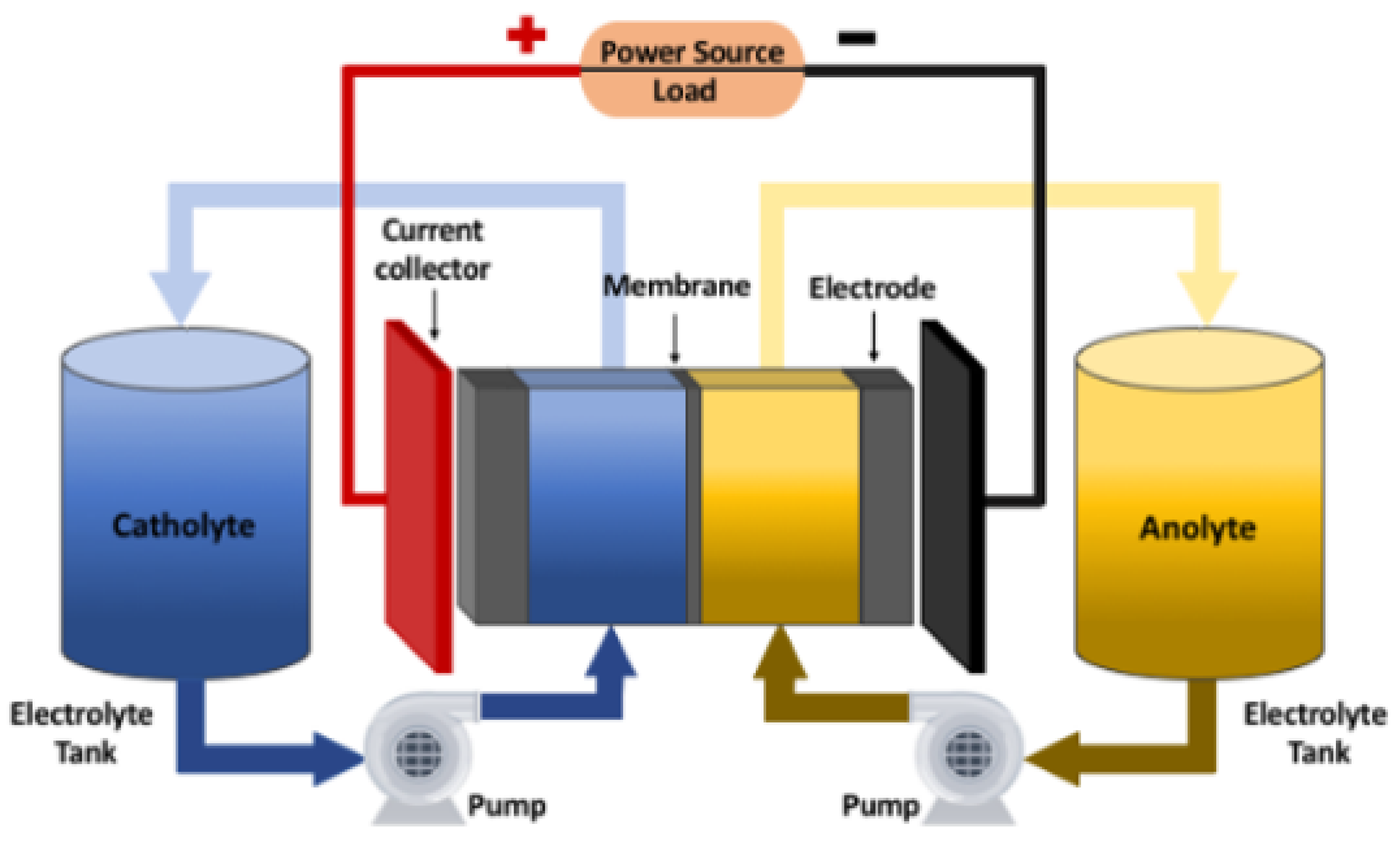
4.8. Flow Batteries Energy Storage System (FBESS)
The energy-storing chemical compounds are in a liquid state and dissolved in the electrolyte in flow batteries, a type of energy storage system that uses a two-electrolyte arrangement. They get around some of the drawbacks of traditional electrochemical accumulators, such lead-acid or nickel-cadmium batteries, which directly store electrochemical reactions as solid molecules on the electrodes. This solid-based approach restricts the mass capacity of standard batteries. In contrast, flow batteries utilize different types of electrolytes, often incorporating bromine as a central element. These electrolytes can include zinc (ZnBr), sodium (NaBr) (Figure 16), vanadium (VBr), and more recently, sodium polysulfide.
The electrochemical reactions in flow batteries experience chemical reactions across a membrane within the cell, and this process can be reversed during the charge-discharge cycle. Through the utilization of extensive reservoirs and connecting numerous cells together, flow batteries can store significant amounts of energy. When needed, the electrolyte is pumped into the reservoirs to release the stored energy. The technology offers several advantages [61,63]:
- Energy capacity and High power .
- Quick recharging by electrolyte replacement.
- Simple electrolyte replacement promotes long life.
- Complete discharge ability.
- The use of non-toxic substances.
- Operation at low temperatures.
However, the system does have a drawback, as it requires moving mechanical components like pumping systems, which make miniaturization challenging. This limitation has restricted its commercial adoption thus far. The most famous flow battery, with a storage capacity of 15 MW-120 MWh, was created by Regenesys Technologies in England in 2003. It has since been upgraded to utilize vanadium as the sole electrochemical system. The overall efficiency of electricity storage for flow batteries is approximately 75% [64].
Figure 16.
Scheme of a Redox flow-battery [65].
Figure 16.
Scheme of a Redox flow-battery [65].
5. Comparison and Evaluation of the Energy Storage Technologies
Various elements of storage technologies are illustrated in the comparison figure below, including technical maturity, application range, efficiency, lifetime, prices, mass and volume densities, and more: These figures serve as a broad comparison and should be considered in the context of specific technologies, applications, and evolving advancements in the energy storage sector.
5.1. Technical Proficiency
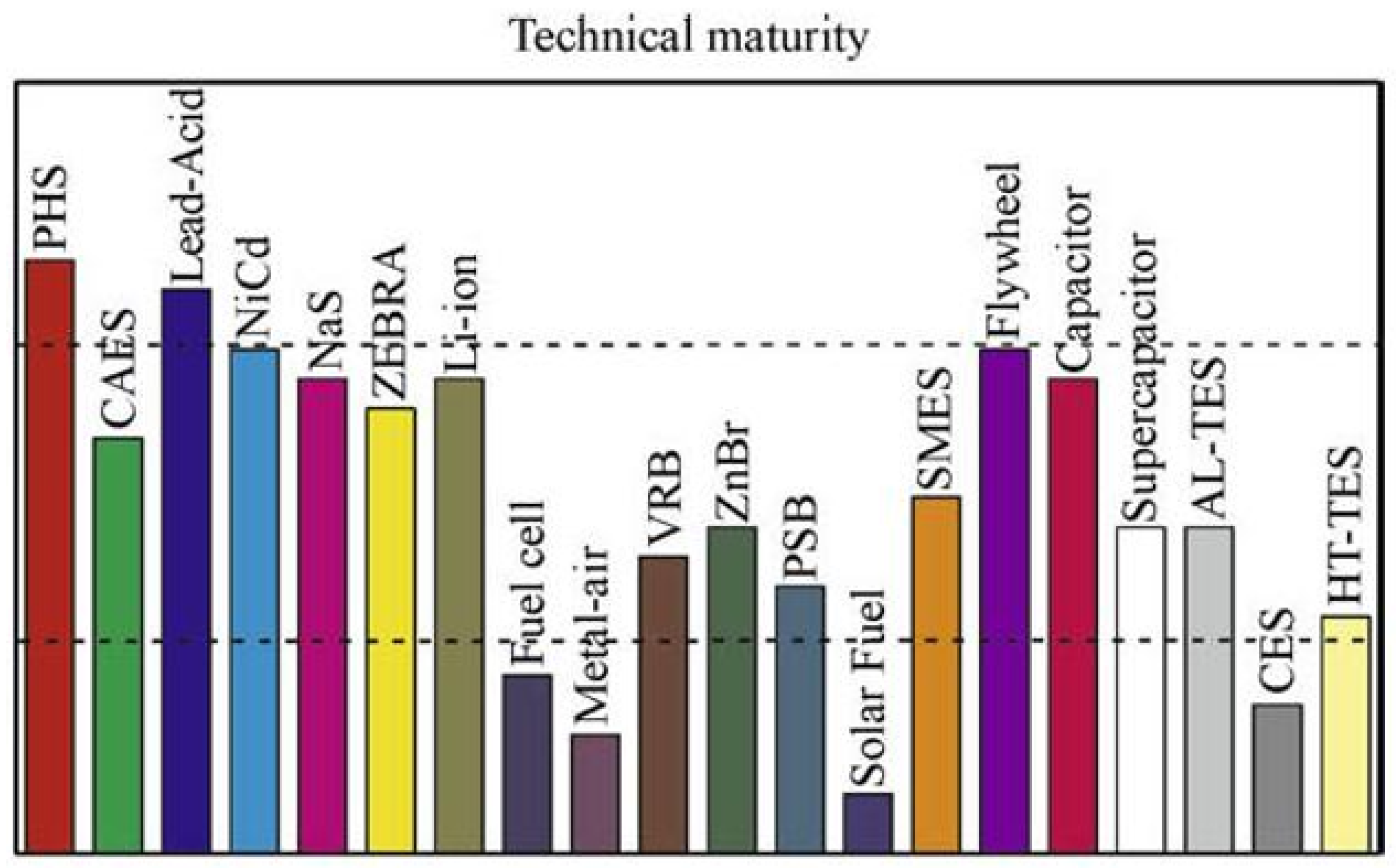
Figure 17 depicts the technical maturity of energy storage systems (EES), which can be divided into three stages of maturity [44]:
- Advanced technologies: Pumped Hydro Storage (PHS) and lead-acid batteries fall into this category as they have been in use for over a century. These technologies have a proven track record and are widely deployed.
- Developed technologies:Examples of developed technologies include Aquiferous Low-Temperature Thermal Energy Storage (Al-TES), High-Temperature Thermal Energy Storage (HT-TES), Superconducting Magnetic Energy Storage (SMES), ZEBRA Li-ion, Flow Batteries, Sodium-Sulfur (NaS), Compressed Air Energy Storage (CAES), and Nickel-Cadmium (NiCd). These systems are now commercially available and have experienced technological advances. To assure their dependability and competitiveness, the electrical sector and the market must still validate and test them further before they can be widely adopted, particularly in large-scale utility applications.
- Developing technologies: Categorized as emerging technologies are Fuel cells, Metal-Air batteries, Solar Fuel, and Cryogenic Energy Storage (CES). Although they are not yet commercially mature, ongoing research and development efforts show their technical feasibility and potential. These emerging technologies hold promise for industrial adoption in the near future, driven by factors such as energy costs and environmental considerations.
It’s worth highlighting that the categorization of EES technologies into these groups is determined by their present level of maturity, market readiness, and deployment status. However, the landscape of energy storage is dynamic, with continuous advancements and evolving market dynamics influencing the growth and adoption of these technologies.
Figure 17.
Technological maturity of energy storage systems [44].
Figure 17.
Technological maturity of energy storage systems [44].
5.2. Discharge Time and Power Rating
Energy storage systems (EES) can be generally classified into three categories based on their intended applications. [53]:
- Energy management: In the realm of large-scale applications exceeding 100 MW, spanning hourly to daily output durations, compressed air energy storage (CAES), cryogenic energy storage (CES), and pumped hydro storage (PHS) stand as viable choices. These systems find utility in load leveling, ramping/load following, and spinning reserve scenarios within energy management. On the other hand, for medium-scale energy management with capacities ranging from 10 to 100 MW, options such as large batteries, flow batteries, fuel cells, CES, and Thermal Energy Storage (TES) hold relevance. [37].
- Power quality: Flywheels, batteries, Superconducting Magnetic Energy Storage (SMES), capacitors, and supercapacitors exhibit rapid response times in the millisecond range, rendering them well-suited for applications necessitating power quality management. These applications include countering momentary voltage drops, resolving flicker-related concerns, and supplying short-duration Uninterruptible Power Supply (UPS) assistance. These technologies are typically employed for power ratings below 1 MW.
- Bridging power: Batteries, flow batteries, fuel cells, and Metal-Air cells showcase relatively swift response times (approximately 1 second) and can maintain power delivery for extended durations, rendering them apt choices for bridging power applications. These technologies are commonly used for power ratings ranging from 100 kW to 10 MW .
It is important to note that the categorization of EES technologies into these application types is based on their characteristics and suitability for specific energy management, power quality, or bridging power scenarios. However, the specific choice of energy storage technology depends on various factors such as project requirements, cost-effectiveness, environmental considerations, and regulatory frameworks.
5.3. Duration of Storage
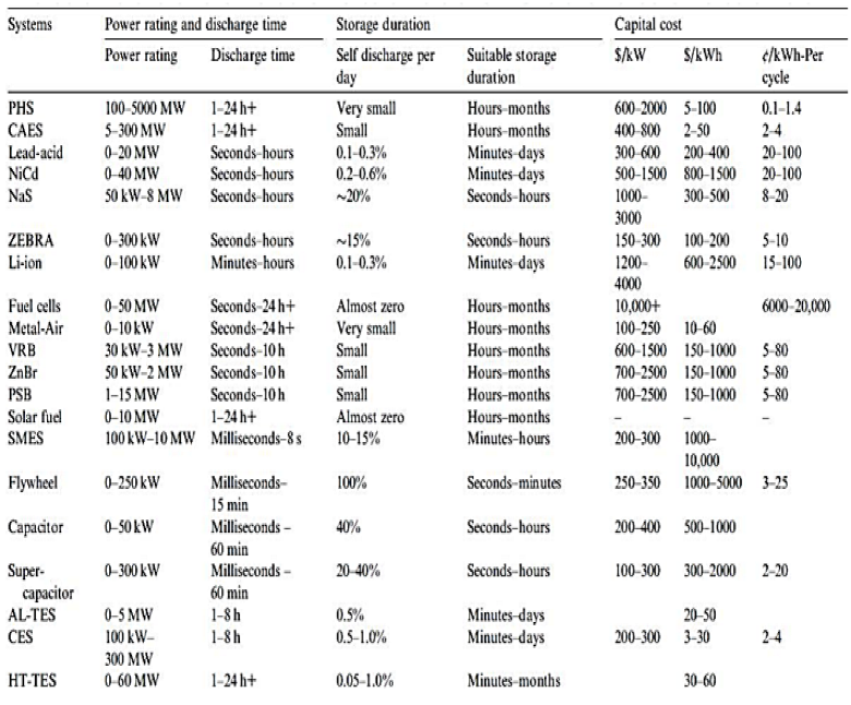
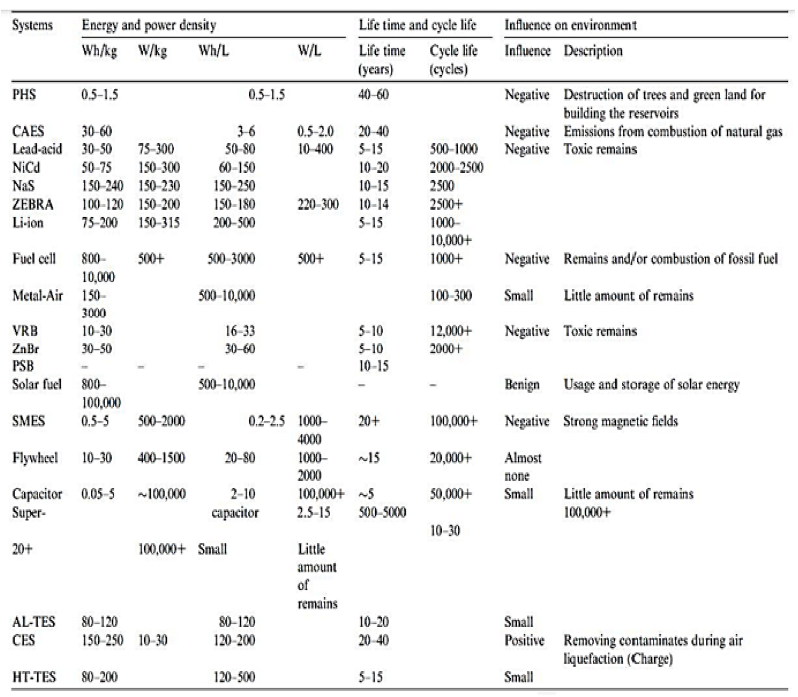
Table 1 provides the daily self-discharge (energy dissipation) for different EES systems, offering insight into the appropriateness of each system for diverse storage durations .
- Energy storage systems (EES) featuring minimal self-discharge rates, including Pumped Hydro Storage (PHS), Compressed Air Energy Storage (CAES), Fuel Cells, Metal-Air Cells, solar fuels, and flow batteries, are optimal choices for extended storage duration. These systems can effectively retain stored energy over extended durations.
- Energy storage systems (EES) characterized by moderate self-discharge rates, such as Lead-Acid, Nickel-Cadmium (NiCd), Lithium-Ion (Li-ion), Thermal Energy Storage (TES), and Cryogenic Energy Storage (CES), are well-matched for storage intervals ranging from a few days to several tens of days. While they exhibit higher self-discharge compared to the aforementioned systems, they still provide reasonable energy retention over moderate timeframes.
- EES systems with extremely high self-discharge ratios of 10–40% per day include sodium-sulfur (NaS), ZEBRA, superconducting magnetic energy storage (SMES), capacitors, and supercapacitors. These systems work best with short cycles periods that last no longer than a few hours. NaS and ZEBRA have significant self-discharge ratios because of their high operating temperatures, which necessitate self-heating to maintain the effectiveness of the stored energy.
- Flywheels, however, will release all of the stored energy if the storage duration extends beyond approximately one day. Therefore, they are most effective for storage periods within tens of minutes, offering rapid discharge capabilities. The selection of an appropriate EES system depends on the desired storage period and the specific requirements of the application. Taking into account the self-discharge characteristics of the system is crucial to ensure efficient and effective energy storage.

Table 1.
Technical characteristics of EES systems [44].
Table 1.
Technical characteristics of EES systems [44].
 |
5.4. Capital Cost
The capital cost is a critical factor influencing the widespread adoption of EES technologies. Table 2 displays different capital cost forms, encompassing cost per kilowatt-hour (kWh), cost per kilowatt (kW), and cost per kilowatt-hour per cycle. For consistency, all the unit energy costs in the table have been normalized by dividing them by the storage efficiency, yielding the cost per output (usable) energy. The per cycle cost is particularly important when evaluating energy storage systems for frequent charge/discharge applications like load leveling.It is determined by dividing the cost per unit energy by the cycle life. This calculation offers a comprehensive evaluation of the energy storage cost across numerous charge/discharge cycles. For example, while lead-acid batteries might have a lower initial capital cost, they might not prove to be the most cost-effective choice for energy management purposes (load leveling), given their comparatively shorter lifespan in such utilization scenarios.
It’s important to highlight that the table does not take into account expenses related to operation and upkeep, disposal, replacement, and other ownership expenditures. This omission is due to limited data availability for some emerging technologies. When assessing the overall cost-effectiveness of EES technologies, these additional expenses should be taken into account [37].
Table 2.
technological features of EES systems are compared [44].
Table 2.
technological features of EES systems are compared [44].
 |
Among the range of EES technologies, CAES, Metal-Air batteries, PHS, TESs, and CES are recognized for their relatively low capital costs per kilowatt-hour (kWh). Although Metal-Air batteries may initially appear appealing because of their elevated energy density and economical initial expense, their limited lifespan and ongoing developmental aspects diminish their attractiveness. In terms of capital costs among developed technologies, CAES emerges as the most cost-effective. Batteries and flow batteries exhibit slightly higher capital costs compared to PHS, but this disparity is gradually narrowing over time. For applications requiring high power and short-duration output, SMES, flywheels, capacitors, and supercapacitors offer a suitable balance between affordability in terms of power output and higher costs associated with storage energy capacity.
When assessing the cost per cycle kWh, PHS and CAES stand out with some of the most favorable values among all EES technologies. While batteries and flow batteries still exhibit higher per cycle costs compared to PHS and CAES, there has been a substantial reduction in these costs in recent years. CES presents itself as a potential contender with low cycle costs, although commercial products are not yet accessible. Fuel cells currently exhibit the highest per cycle cost, and it might require a considerable amount of time for them to achieve economic competitiveness. Solar fuels, being in their nascent stages of development, have limited available data for analysis [66].
It is important to note that the capital cost of energy storage systems can vary significantly from the estimations provided here due to factors such as technological breakthroughs, construction timeline, location, and system size. The information presented should be considered preliminary and subject to change as the field progresses.
5.5. Cycle Efficiency
Cycle efficiency, representing the "round-trip" efficiency, signifies the ratio of output energy to input energy, excluding losses due to self-discharge during storage. EES systems can be broadly categorized into three groups based on their cycle efficiency:
- Exceptionally high efficiency: SMES, flywheel, supercapacitor, and Li-ion battery demonstrate an exceptional cycle efficiency of more than 90%.
- High cycle efficiency: The cycle efficiencies of PHS, CAES, batteries (other than Li-ion), flow batteries, and conventional capacitors range from 60% to 90%. It is important to note that PHS, which involves pumping and releasing water, often has higher efficiency than CAES, which compresses and expands air. Gas is heated when it is compressed quickly, which raises its pressure and necessitates more energy for subsequent compression.
- Moderate to low efficiency: TESs, DMFCs, Metal-Air, solar fuel, hydrogen, and DMFCs (Direct Methanol Fuel Cell) exhibit moderate to low cycle efficiencies, falling below 60%. These systems primarily encounter substantial losses during the conversion from the commercial AC system to the storage system side. For instance, the power stored through hydrogen experiences a relatively lower round-trip energy efficiency (ranging between 20% and 50%) due to a combination of electrolyzer efficiency and the efficiency of reconversion back to electricity. It’s worth noting that a trade-off exists between capital cost and round-trip efficiency. A storage technology characterized by lower capital cost and round-trip efficiency could still present effective competition against a technology with higher capital cost and efficiency.
5.6. Power density
Power density is calculated by dividing the rated output power of an energy storage system by its volume, usually measured in W/kg or W/liter. On the other hand, energy density is determined by dividing the stored energy amount by the volume of the storage device. It’s important to note that the volume of the storage device includes not only the energy-storing component but also additional elements such as accessories, support structures, and the inverter system.
Table 1 demonstrates the exceptionally high energy densities of solar fuels, metal-air batteries, and fuel cells, which are typically around 1000 Wh/kg. However, as was already indicated, they typically have relatively low cycle efficiencies. Medium energy densities are demonstrated by batteries, TESs, CESs, and CAESs.
The energy densities of PHS, SMES, capacitor/supercapacitor, and flywheel systems usually fall below 30 Wh/kg. Nonetheless, due to their high power densities, SMES, capacitor/supercapacitor, and flywheel systems are well suited for applications that call for high-quality power, sizable discharge currents, and quick responses [53]. In contrast to conventional batteries, NaS and Li-ion batteries exhibit greater energy densities, whereas flow batteries demonstrate somewhat reduced energy densities. Importantly, variations in energy density can arise within a given type of EES when produced by different manufacturers.
5.7. Lifetime and cycle life
The lifespan and/or cycle life of several EES systems are compared in Table 1. It is clear that EES systems with a focus on electrical technology frequently have cycle lives that are quite lengthy, frequently exceeding 20,000 cycles. These systems include SMES, capacitors, and supercapacitors as examples.Extended operational lifespans are a notable trait of mechanical and thermal energy storage systems, such as Pumped Hydro Storage (PHS), Compressed Air Energy Storage (CAES), flywheels, Adiabatic Liquid Thermal Energy Storage (AL-TES), Cryogenic Energy Storage (CES), and High-Temperature Thermal Energy Storage (HT-TES). These techniques draw upon conventional principles of mechanical engineering, with their durability predominantly determined by the longevity of their mechanical components.
On the other hand, due to chemical degradation over time, batteries, flow batteries, and fuel cells experience notable declines in cycle capacities in comparison to alternative systems. There is a need for more research since Metal-Air batteries, in particular, have a short lifespan of only a few hundred cycles.
6. Conclusion
By critically reviewing existing literature,this study offers valuable perspectives on the present status of energy storage within MV-LV networks. It highlights the potential benefits of integrating energy storage technologies into these networks, such as improved grid stability, enhanced renewable energy integration, and optimized load management. Furthermore, the review sheds light on the challenges and limitations that need to be addressed for successful implementation. While there is an associated cost with energy storage, it has been observed that storage is already proving to be cost-effective in many cases. As research and development in the field continue to progress, additional application possibilities are expected to emerge [55]. The growing presence of decentralized and renewable energy sources in power networks has made storage a crucial factor. In addition to being a technical network management solution that guarantees real-time load balancing, it also promotes the best possible use of renewable resources by preventing load shedding during times of overproduction. Decentralized storage has the ability to increase the resilience of power networks through the construction of energy farms that serve particular demand zones when combined with local renewable energy output. There are several ways to improve system security, but their vastly different requirements make it difficult to directly compare them. In order to improve the performance and cost projections for storage systems, it was our goal to develop a set of technical and economic parameters.The conclusions drawn from this review can steer researchers, policymakers, and industry experts towards advancing the growth and implementation of energy storage systems on MV-LV networks, aiming for a future of sustainable and robust energy solutions.The following findings can be drawn from the review [53,54,67,68]:
- While an array of commercially accessible energy storage systems (EES) exists, there isn’t a singular system that meets all the criteria of an ideal EES, encompassing attributes like maturity, extended lifespan, cost-effectiveness, high density, superior efficiency, and eco-friendliness. Each EES finds its niche within a specific application domain. Pumped Hydro Storage (PHS), Compressed Air Energy Storage (CAES), large-scale batteries, flow batteries, fuel cells, solar fuels, Thermal Energy Storage (TES), and Cryogenic Energy Storage (CES) are well-suited for energy management applications. Flywheels, batteries, capacitors, and supercapacitors find better alignment with power quality and short-duration Uninterruptible Power Supply (UPS) needs. Batteries, flow batteries, fuel cells, and Metal-Air cells exhibit potential for bridging power applications.
- Certain energy storage technologies, such as Pumped Hydro Storage (PHS) and lead-acid batteries, have attained technical maturity. Compressed Air Energy Storage (CAES), Nickel-Cadmium (NiCd), Sodium-Sulfur (NaS), ZEBRA Li-ion, flow batteries, Superconducting Magnetic Energy Storage (SMES), flywheels, capacitors, supercapacitors, Adiabatic Liquid Thermal Energy Storage (AL-TES), and High-Temperature Thermal Energy Storage (HT-TES) are both technically developed and commercially available. On the other hand, fuel cells, Metal-Air batteries, solar fuels, and Cryogenic Energy Storage (CES) are still in the developmental stages. Among the established technologies, CAES holds the advantage of having the lowest capital cost, while Metal-Air batteries have the potential to emerge as the most cost-effective among the recognized EES systems.
- Superconducting Magnetic Energy Storage (SMES), flywheels, capacitors/supercapacitors, Pumped Hydro Storage (PHS), Compressed Air Energy Storage (CAES), batteries, and flow batteries showcase cycle efficiencies surpassing 60%. Conversely, fuel cells, Direct Methanol Fuel Cells (DMFC), Metal-Air batteries, solar fuels, Thermal Energy Storage (TES), and Cryogenic Energy Storage (CES) demonstrate lower efficiencies attributed to substantial losses during the conversion process from commercial AC to the stored energy state.
- Energy storage systems (EES) rooted in electrical technologies, like SMES, capacitors, and supercapacitors, boast extended cycle lifespans. Similarly, EES systems grounded in mechanical and thermal principles, encompassing Pumped Hydro Storage (PHS), Compressed Air Energy Storage (CAES), flywheels, Adiabatic Liquid Thermal Energy Storage (AL-TES), Cryogenic Energy Storage (CES), and High-Temperature Thermal Energy Storage (HT-TES), also exhibit prolonged cycle lives. Batteries, flow batteries, and fuel cells have comparatively lower cycle lives due to chemical deterioration over time. Currently, Metal-Air batteries have the shortest lifespan.
- Certain energy storage technologies, including Pumped Hydro Storage (PHS), Compressed Air Energy Storage (CAES), batteries, flow batteries, fuel cells, and Superconducting Magnetic Energy Storage (SMES), may pose potential adverse environmental impacts due to factors like fossil fuel combustion, intense magnetic fields, landscape disruption, and the generation of toxic byproducts. Solar fuels and Cryogenic Energy Storage (CES) are generally regarded as more ecologically benign, although a thorough life-cycle analysis is imperative to establish definitive conclusions. In light of the insights gleaned from this study and a diligent assessment of the implications, the subsequent conclusions can be derived:
- Developing storage techniques requires improving and optimizing power electronics, which hold a pivotal role in transforming electricity into storable energy and vice versa.
- As renewable energy integration expands, it becomes imperative to examine the influence of various storage alternatives, especially decentralized ones, on network resilience, infrastructure, and the overall costs of energy production.
- Performing comprehensive system analyses that encompass storage, related electricity conversion, power electronics, and control systems will advance the optimization of approaches related to cost, efficiency, reliability, maintenance, as well as societal and environmental considerations, among other factors.
- Assessing the national significance of compressed gas storage methods holds importance.
- Allocating resources to research and development that integrates various storage methodologies with renewable energy sources will enhance overall system efficiency and mitigate greenhouse gas emissions originating from conventional gas-burning power plants.
- Evaluating the capabilities of high-temperature thermal storage systems, which provide notable benefits in power distribution, can facilitate their secure implementation in close proximity to power consumption regions.
- Progressing in the field of supercapacitors will result in their incorporation across a spectrum of applications.
- Creating cost-effective, durable flywheel storage systems will unleash their potential, especially in decentralized applications.
- A collaborative research and development (R&D) effort is required to accelerate the adoption and utilization of hydrogen-electrolyzer fuel-cell storage systems.
Author Contributions
Mr Mushid is the primary researcher in this paper .He has contributed by selecting the topic , formulating the problem ,proposing a solution to the problem by undertaking an extensive survey on the proposed topic. Dr Khan has contributed by offering supervisory support.
Funding
This research received no external funding.
Conflicts of Interest
The authors declare no conflict of interest.
Abbreviations
| MDPI | Multidisciplinary Digital Publishing Institute |
| DOAJ | Directory of open access journals |
| TLA | Three letter acronym |
| LD | Linear dichroism |
References
- Smith, S.C.; Sen, P.; Kroposki, B. Advancement of energy storage devices and applications in electrical power system. In Proceedings of the 2008 IEEE Power and Energy Society General Meeting-Conversion and Delivery of Electrical Energy in the 21st Century. IEEE, 2008, pp. 1–8.
- Salvarli, M.S.; Salvarli, H. For sustainable development: Future trends in renewable energy and enabling technologies. In Renewable energy-resources, challenges and applications; IntechOpen, 2020.
- Ghosh, P.; Emonts, B.; Janßen, H.; Mergel, J.; Stolten, D. Ten years of operational experience with a hydrogen-based renewable energy supply system. Solar Energy 2003, 75, 469–478. [Google Scholar] [CrossRef]
- Kraftnät, S. Information om stödtjänster. Svenska Kraftnät 2020, 26. [Google Scholar]
- Siddiq, A. Sizing and optimization of battery energy storage system for wind and solar power plant in a distribution grid: A case study on optimizing the size of the battery for peak shaving and ancillary services, 2021.
- Hamsic, N.; Schmelter, A.; Mohd, A.; Ortjohann, E.; Schultze, E.; Tuckey, A.; Zimmermann, J. Stabilising the grid voltage and frequency in isolated power systems using a flywheel energy storage system. In Proceedings of the The Great Wall World Renewable Energy Forum, 2006, number October, pp. 1–6. 1–6.
- Ibrahim, H.; Beguenane, R.; Merabet, A. Technical and financial benefits of electrical energy storage. In Proceedings of the 2012 IEEE Electrical Power and Energy Conference. IEEE, 2012, pp. 86–91.
- McDowall, J.A. Status and outlook of the energy storage market. In Proceedings of the 2007 IEEE Power Engineering Society General Meeting. IEEE, 2007, pp. 1–3.
- Baker, J.; Collinson, A. Electrical energy storage at the turn of the millennium. Power Engineering Journal 1999, 13, 107–112. [Google Scholar] [CrossRef]
- Badgotra, N. Energy Storage in Power Applications. International Journal of Analysis of Electrical Machines 2017, 3, 8–16. [Google Scholar]
- Ahearne, J. Storage of electric energy, Report on research and development of energy technologies. International Union of Pure and Applied Physics 2004, 76, 86. [Google Scholar]
- Connolly, D. A review of energy storage technologies: for the integration of fluctuating renewable energy 2010.
- Van Der Linden, S. The commercial world of energy storage: a review of operating facilities. 2003 1 st Annual Conference of the Energy Storage Council, Houston TX, 2003.
- Sobczyński, D.; Pawłowski, P. Energy storage systems for renewable energy sources. 2021 Selected Issues of Electrical Engineering and Electronics (WZEE), 2021; 1–4. [Google Scholar]
- Walawalkar, R.; Apt, J.; Mancini, R. Economics of electric energy storage for energy arbitrage and regulation in New York. Energy Policy 2007, 35, 2558–2568. [Google Scholar] [CrossRef]
- Chen, H.; Cong, T.N.; Yang, W.; Tan, C.; Li, Y.; Ding, Y. Progress in electrical energy storage system: A critical review. Progress in natural science 2009, 19, 291–312. [Google Scholar] [CrossRef]
- Bueno, C.; Carta, J.A. Wind powered pumped hydro storage systems, a means of increasing the penetration of renewable energy in the Canary Islands. Renewable and sustainable energy reviews 2006, 10, 312–340. [Google Scholar] [CrossRef]
- Zyglakis, L.; Bintoudi, A.D.; Bezas, N.; Isaioglou, G.; Gkaidatzis, P.A.; Tryferidis, A.; Tzovaras, D.; Parcharidis, S. Energy Storage Systems in Residential Applications for Optimised Economic Operation: Design and Experimental Validation. In Proceedings of the 2021 IEEE PES Innovative Smart Grid Technologies-Asia (ISGT Asia). IEEE, 2021, pp. 1–5.
- Najjar, Y.S.; Zaamout, M.S. Performance analysis of compressed air energy storage (CAES) plant for dry regions. Energy conversion and management 1998, 39, 1503–1511. [Google Scholar] [CrossRef]
- Wang, S.; Chen, G.; Fang, M.; Wang, Q. A new compressed air energy storage refrigeration system. Energy Conversion and Management 2006, 47, 3408–3416. [Google Scholar] [CrossRef]
- Cook, G.; Spindler, W.; Grefe, G. Overview of battery power regulation and storage. IEEE Transactions on Energy Conversion 1991, 6, 204–211. [Google Scholar] [CrossRef]
- Santos, R.J.; Andre, R.; Bessa, R.; Gouveia, C.; Araujo, A.; Guerra, F.; DamáSio, J.; Bravo, G.; Sumaili, J. Energy storage management for grid operation purposes. In Proceedings of the CIRED Workshop 2016. IET, 2016, pp. 1–4.
- Karpinski, A.; Makovetski, B.; Russell, S.; Serenyi, J.; Williams, D. Silver–zinc: status of technology and applications. Journal of Power Sources 1999, 80, 53–60. [Google Scholar] [CrossRef]
- Chalk, S.G.; Miller, J.F. Key challenges and recent progress in batteries, fuel cells, and hydrogen storage for clean energy systems. Journal of Power Sources 2006, 159, 73–80. [Google Scholar] [CrossRef]
- Weinmann, O. Hydrogen-the flexible storage for electrical energy. Power Engineering Journal 1999, 13, 164–170. [Google Scholar] [CrossRef]
- Kolkert, W.J.; Jamet, F. Electric energy gun technology: status of the French-German-Netherlands programme. IEEE transactions on magnetics 1999, 35, 25–30. [Google Scholar] [CrossRef]
- Xue, X.; Cheng, K.W.E.; Sutanto, D. A study of the status and future of superconducting magnetic energy storage in power systems. Superconductor Science and Technology 2006, 19, R31. [Google Scholar] [CrossRef]
- Van der Linden, S. Bulk energy storage potential in the USA, current developments and future prospects. Energy 2006, 31, 3446–3457. [Google Scholar] [CrossRef]
- Ibrahim, H.; Ilinca, A. Techno-economic analysis of different energy storage technologies. In Energy Storage-Technologies and Applications; IntechOpen, 2013.
- Carmen. Beacon Power Stephentown - flywheel energy storage system, US, 2021.
- Rosen, M. Second-law analysis of aquifer thermal energy storage systems. Energy 1999, 24, 167–182. [Google Scholar] [CrossRef]
- Chen, H.; Ding, Y.; Peters, T.; Berger, F. Method of storing energy and a cryogenic energy storage system, 2016. US Patent App. 15/053,840.
- Xue, X.; Wang, S.; Zhang, X.; Cui, C.; Chen, L.; Zhou, Y.; Wang, J. Thermodynamic analysis of a novel liquid air energy storage system. Physics procedia 2015, 67, 733–738. [Google Scholar] [CrossRef]
- Yepes-Fernéndez, H.; Restrepo, M.; Arango-Manrique, A. A study on control strategies for aggregated community energy storage systems in medium voltage distribution networks. IEEE Access 2022, 10, 119321–119332. [Google Scholar] [CrossRef]
- Nadeem, F.; Hussain, S.S.; Tiwari, P.K.; Goswami, A.K.; Ustun, T.S. Comparative review of energy storage systems, their roles, and impacts on future power systems. IEEE access 2018, 7, 4555–4585. [Google Scholar] [CrossRef]
- Weinstock, I.B. Recent advances in the US Department of Energy’s energy storage technology research and development programs for hybrid electric and electric vehicles. Journal of Power Sources 2002, 110, 471–474. [Google Scholar] [CrossRef]
- Storage, C.A.E.; Japan, O. Pumped Hydro Storage.
- Ibrahim, H.; Ilinca, A.; Younes, R.; Perron, J.; Basbous, T. Study of a hybrid wind-diesel system with compressed air energy storage. In Proceedings of the 2007 IEEE Canada Electrical Power Conference. IEEE, 2007, pp. 320–325.
- Farhadi, M.; Mohammed, O. Energy storage systems for high power applications. In Proceedings of the 2015 IEEE Industry Applications Society Annual Meeting. IEEE, 2015, pp. 1–7.
- Bari, R.T.B.; Rahman, T.; Punny, M.J.; Mian, M.M.; Faisal, F.; Nishat, M.M. Investigation of the Impact of AC Harmonics on Lead Acid Battery Degradation. In Proceedings of the 2023 IEEE IAS Global Conference on Emerging Technologies (GlobConET). IEEE, 2023, pp. 1–5.
- Ibrahim, H.; Ilinca, A.; Perron, J. Solutions actuelles pour une meilleure gestion et intégration de la ressource éolienne 2008.
- Ratering-Schnitzler, B.; Harke, R.; Schroeder, M.; Stephanblome, T.; Kriegler, U. Voltage quality and reliability from electrical energy-storage systems. Journal of power sources 1997, 67, 173–177. [Google Scholar] [CrossRef]
- Walawalkar, R.; Apt, J. Market analysis of emerging electric energy storage systems. National Energy Technology Laboratory, 2008; 1–118. [Google Scholar]
- Rebours, Y.; Kirschen, D. What is spinning reserve. The University of Manchester 2005, 174.
- Wu, P.; Bucknall, R. Hybrid fuel cell and battery propulsion system modelling and multi-objective optimisation for a coastal ferry. International journal of hydrogen energy 2020, 45, 3193–3208. [Google Scholar] [CrossRef]
- Eyer, J.M.; Corey, G.P.; Iannucci Jr, J.J. Energy storage benefits and market analysis handbook: a study for the DOE Energy Storage Systems Program. Technical report, Sandia National Laboratories (SNL), Albuquerque, NM, and Livermore, CA …, 2004.
- Eyer, J.; Corey, G. Energy storage for the electricity grid: Benefits and market potential assessment guide. Sandia National Laboratories 2010, 20, 5. [Google Scholar]
- Yang, B.; Pan, J.; Zhu, Y.; Huang, X.; Wang, C.; Guo, C.; Guo, Y. A review of energy storage system study. In Proceedings of the 2020 IEEE 4th Conference on Energy Internet and Energy System Integration (EI2). IEEE, 2020, pp. 2858–2863.
- Eckroad, S.; Gyuk, I. EPRI-DOE handbook of energy storage for transmission & distribution applications. Electric Power Research Institute, Inc, 2003; 3–35. [Google Scholar]
- Schoenung, S.M.; Hassenzahl, W.V. Long-vs. short-term energy storage technologies analysis: a life-cycle cost study: a study for the DOE energy storage systems program. Technical report, Sandia National Laboratories (SNL), Albuquerque, NM, and Livermore, CA …, 2003.
- Gergaud, O. Modélisation énergétique et optimisation économique d’un système de production éolien et photovoltaïque couplé au réseau et associé à un accumulateur. PhD thesis, École normale supérieure de Cachan-ENS Cachan, 2002.
- Messenger, R.A.; Abtahi, A. Photovoltaic systems engineering; CRC press, 2018.
- Ibrahim, H.; Ilinca, A.; Perron, J. Energy storage systems—Characteristics and comparisons. Renewable and sustainable energy reviews 2008, 12, 1221–1250. [Google Scholar] [CrossRef]
- Faisal, M.; Hannan, M.A.; Ker, P.J.; Hussain, A.; Mansor, M.B.; Blaabjerg, F. Review of energy storage system technologies in microgrid applications: Issues and challenges. Ieee Access 2018, 6, 35143–35164. [Google Scholar] [CrossRef]
- Multon, B.; Ruer, J. Stocker l’électricité: oui, c’est indispensable et c’est possible. Pourquoi, où, comment? Publication ECRIN en contribution au débat national sur l’énergie, 2003. [Google Scholar]
- Amiryar, M.E.; Pullen, K.R. A review of flywheel energy storage system technologies and their applications. Applied Sciences 2017, 7, 286. [Google Scholar] [CrossRef]
- Robyns, B.; Ansel, A.; Davigny, A.; Saudemont, C.; Cimuca, G. Contribution du stockage de l’énergie électrique à la participation aux services système des éoliennes 2005.
- Anzano, J.; Jaud, P.; Madet, D. Stockage de l’électricité dans le système de production électrique. Techniques de l’ingénieur, traité de Génie Électrique D 1989, 4030, 09. [Google Scholar]
- Coppez, G.; Chowdhury, S.; Chowdhury, S. South African renewable energy hybrid power system storage needs, challenges and opportunities. In Proceedings of the 2011 IEEE Power and Energy Society General Meeting. IEEE, 2011, pp. 1–9.
- Robin, G.; Ruellan, M.; Multon, B.; Ahmed, H.B.; Glorennec, P.Y. Solutions de stockage de l’énergie pour les systèmes de production intermittente d’électricité renouvelable. In Proceedings of the Colloque SeaTechWeek 2004 (Semaine Internat. des Technologies de la Mer), 2004, p. 9p.
- Chatrung, N. Battery energy storage system (bess) and development of grid scale bess in egat. In Proceedings of the 2019 IEEE PES GTD Grand International Conference and Exposition Asia (GTD Asia). IEEE, 2019, pp. 589–593.
- Faure, F. Suspension magnetique pour volant d’inertie. PhD thesis, Institut National Polytechnique de Grenoble-INPG, 2003.
- Vazquez, S.; Lukic, S.M.; Galvan, E.; Franquelo, L.G.; Carrasco, J.M. Energy storage systems for transport and grid applications. IEEE Transactions on industrial electronics 2010, 57, 3881–3895. [Google Scholar] [CrossRef]
- Bhatnagar, N.; Venkatesh, B. Energy storage and power systems. In Proceedings of the 2012 25th IEEE Canadian Conference on Electrical and Computer Engineering (CCECE). IEEE, 2012, pp. 1–4.
- Clemente, A.; Costa-Castelló, R. Redox flow batteries: A literature review oriented to automatic control. Energies 2020, 13, 4514. [Google Scholar] [CrossRef]
- Acp. The American Clean Power Association (ACP), 2023.
- Arfoa, A.A.; Almaita, E.; Alshkoor, S.; Shloul, M. Techno-Economic Feasibility Analysis of On-Grid Battery Energy Storage System: Almanara PV Power Plant Case Study. Jordan Journal of Electrical Engineering. All rights reserved-Volume 2022, 8, 254. [Google Scholar] [CrossRef]
- Petinrin, J.; Shaaban, M. Implementation of energy storage in a future smart grid. Australian Journal of Basic and Applied Sciences 2013, 7, 273–279. [Google Scholar]
Figure 1.
Basic principle of energy storage [37].
Figure 1.
Basic principle of energy storage [37].
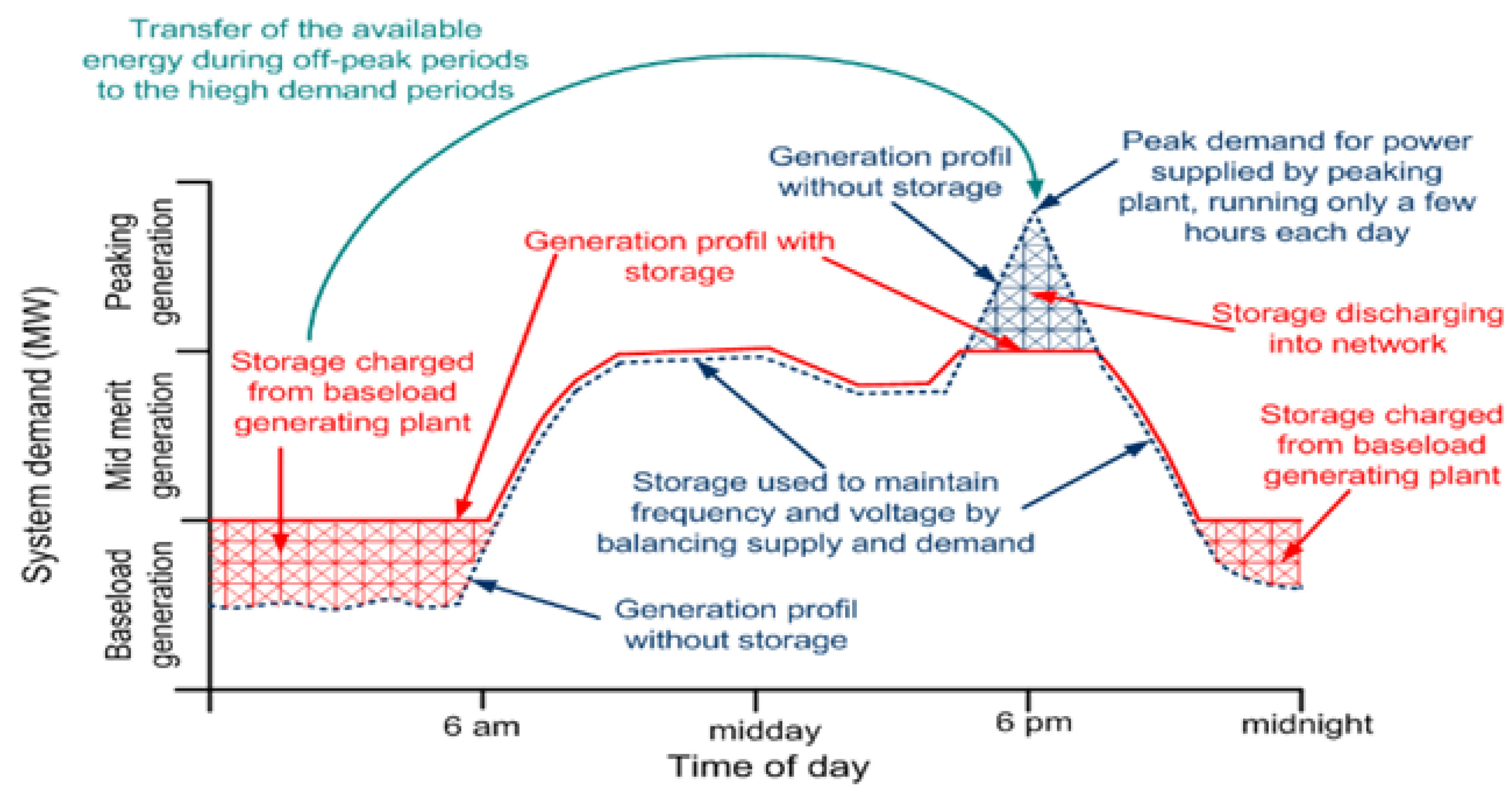
Figure 2.
Value chain using energy storage technologies [7].
Figure 2.
Value chain using energy storage technologies [7].
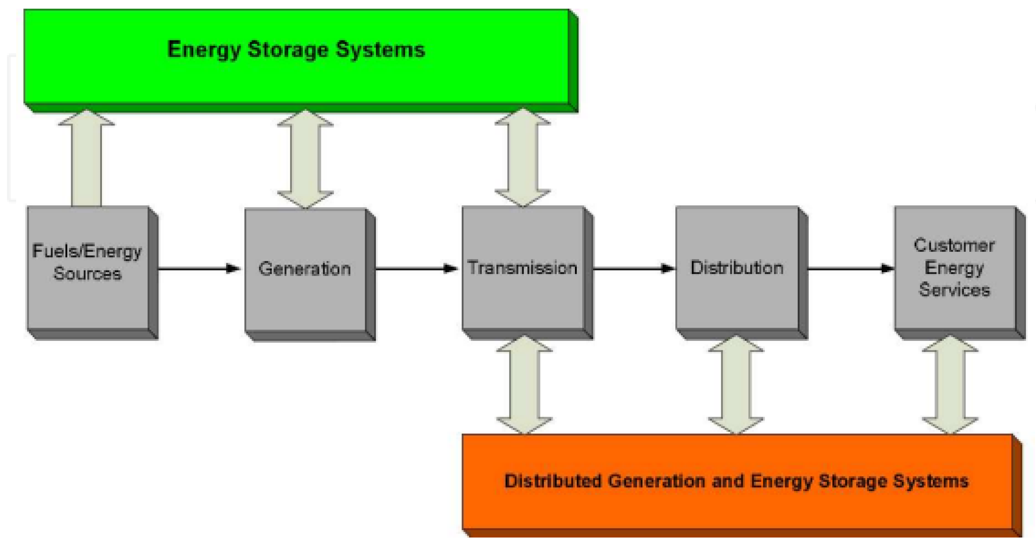
Figure 3.
Utilization of energy storage within the power system [43].
Figure 3.
Utilization of energy storage within the power system [43].
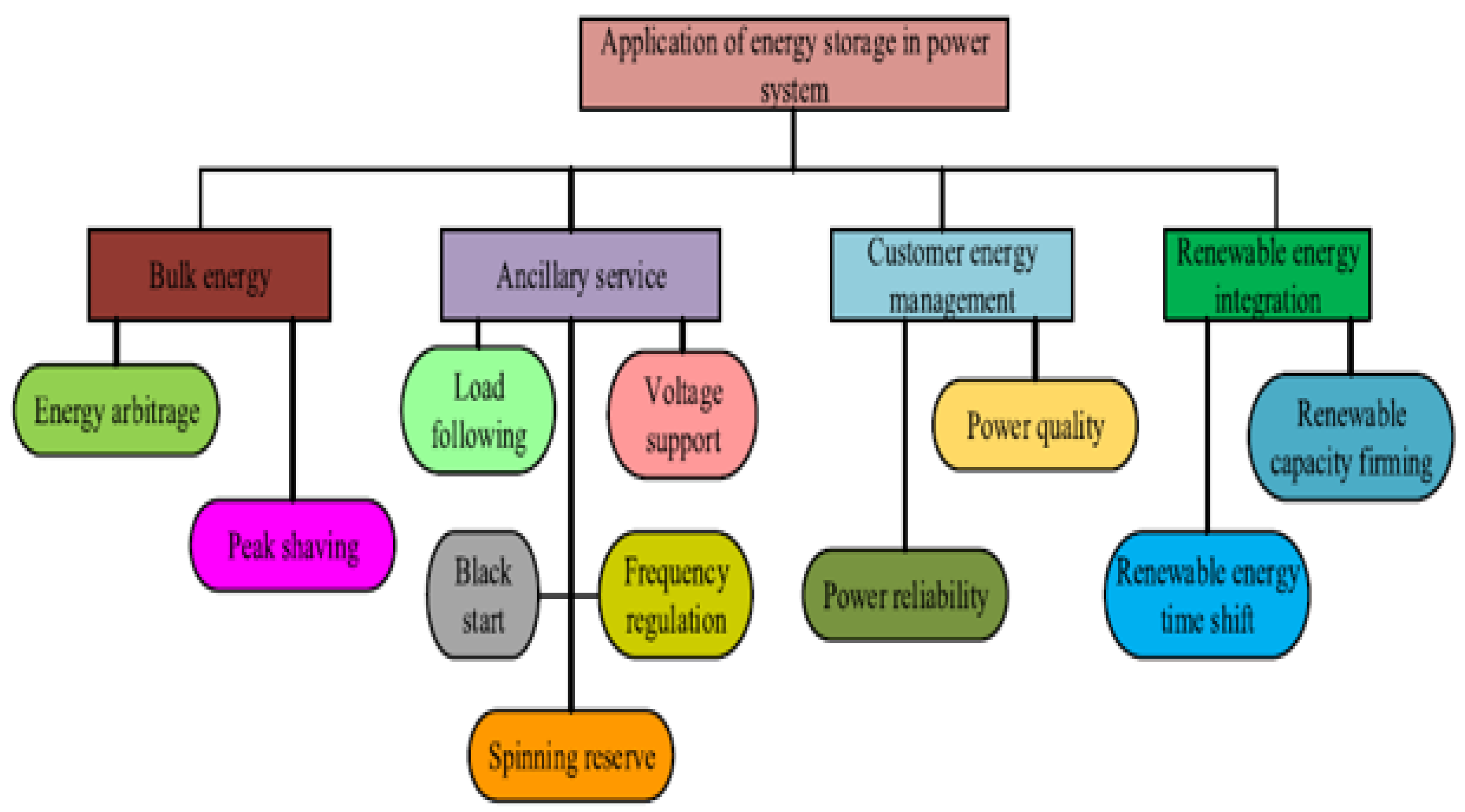
Figure 4.
Provides examples of the technical advantages of energy storage systems [41].
Figure 4.
Provides examples of the technical advantages of energy storage systems [41].
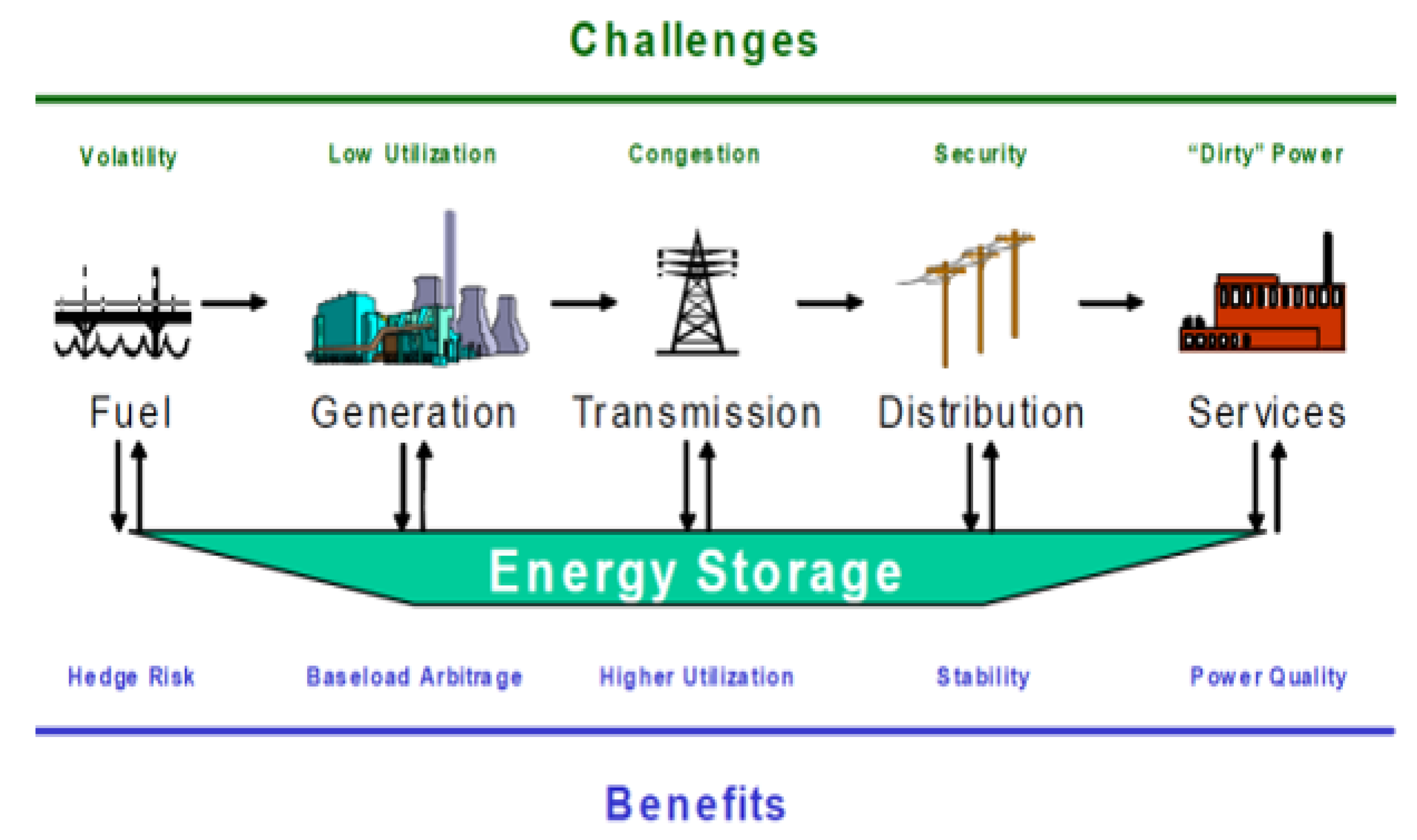
Figure 6.
Power efficiency and state of charge [51].
Figure 6.
Power efficiency and state of charge [51].
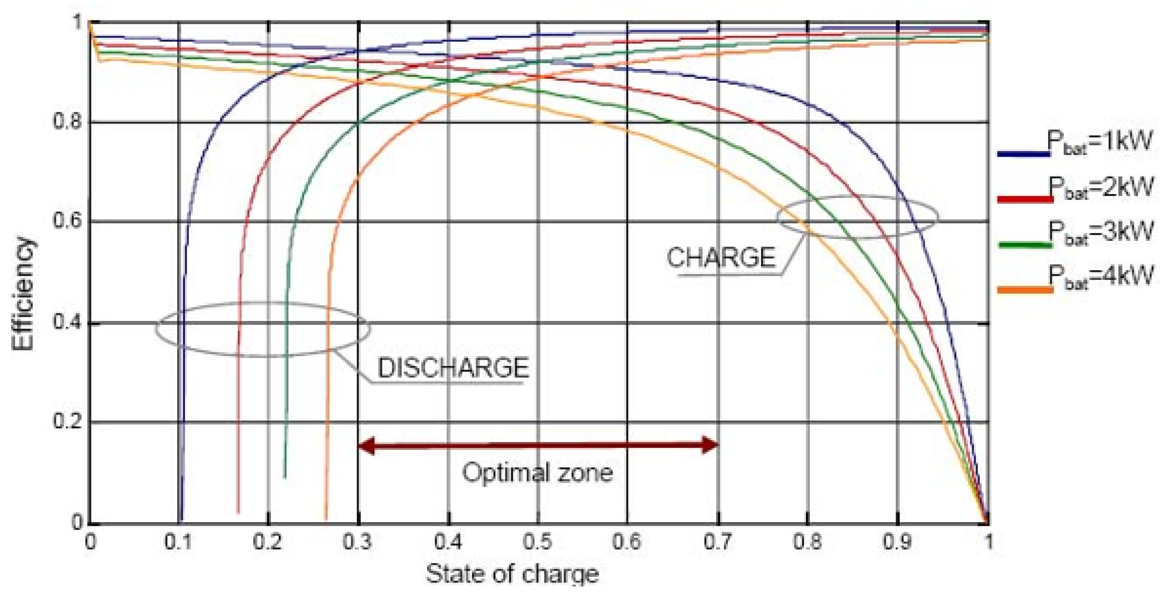
Figure 7.
Example of lead-acid battery Depth of discharge [52].
Figure 7.
Example of lead-acid battery Depth of discharge [52].
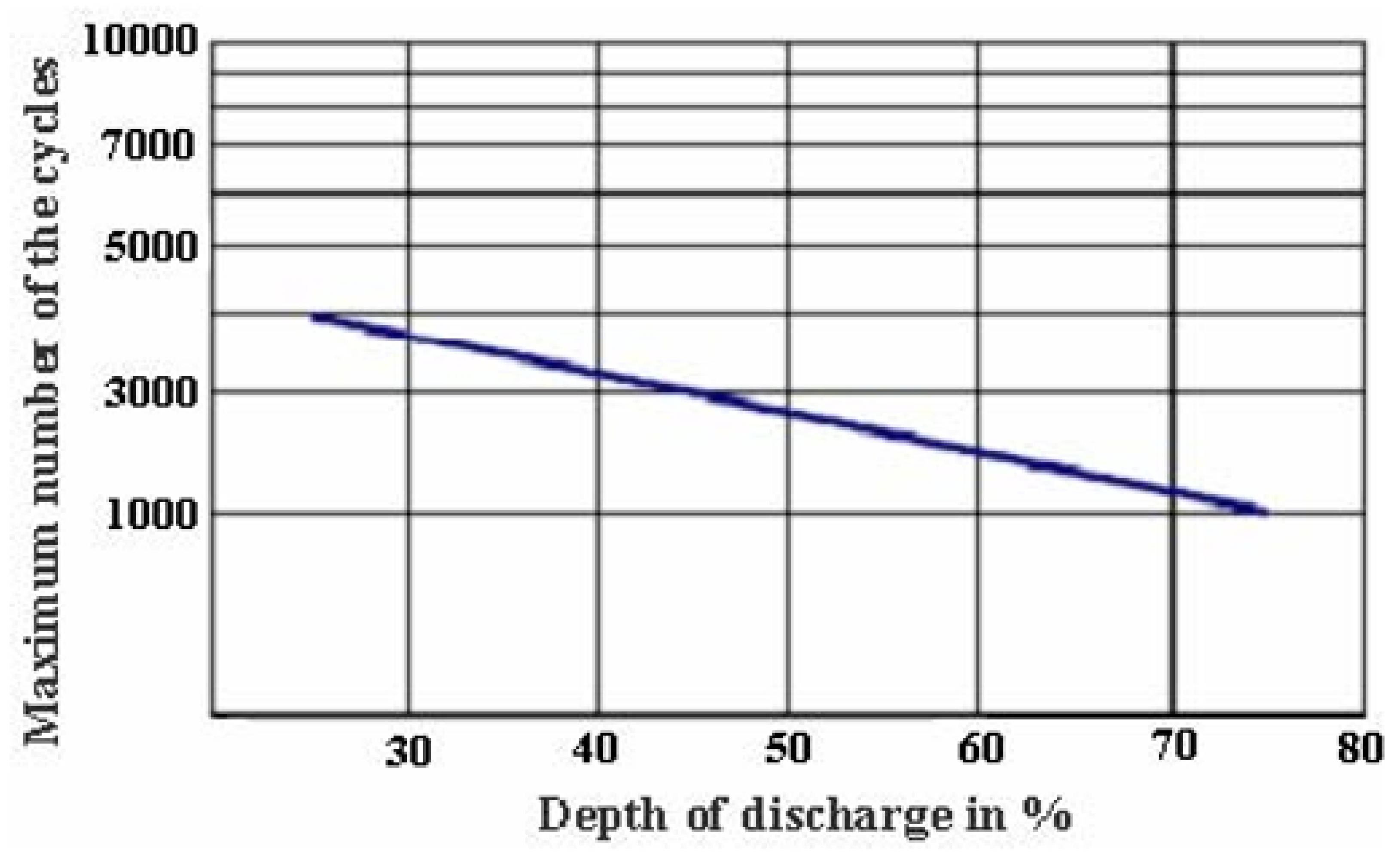
Figure 8.
Variable operating costs for energy storage systems with 75% storage efficiency [47].
Figure 8.
Variable operating costs for energy storage systems with 75% storage efficiency [47].
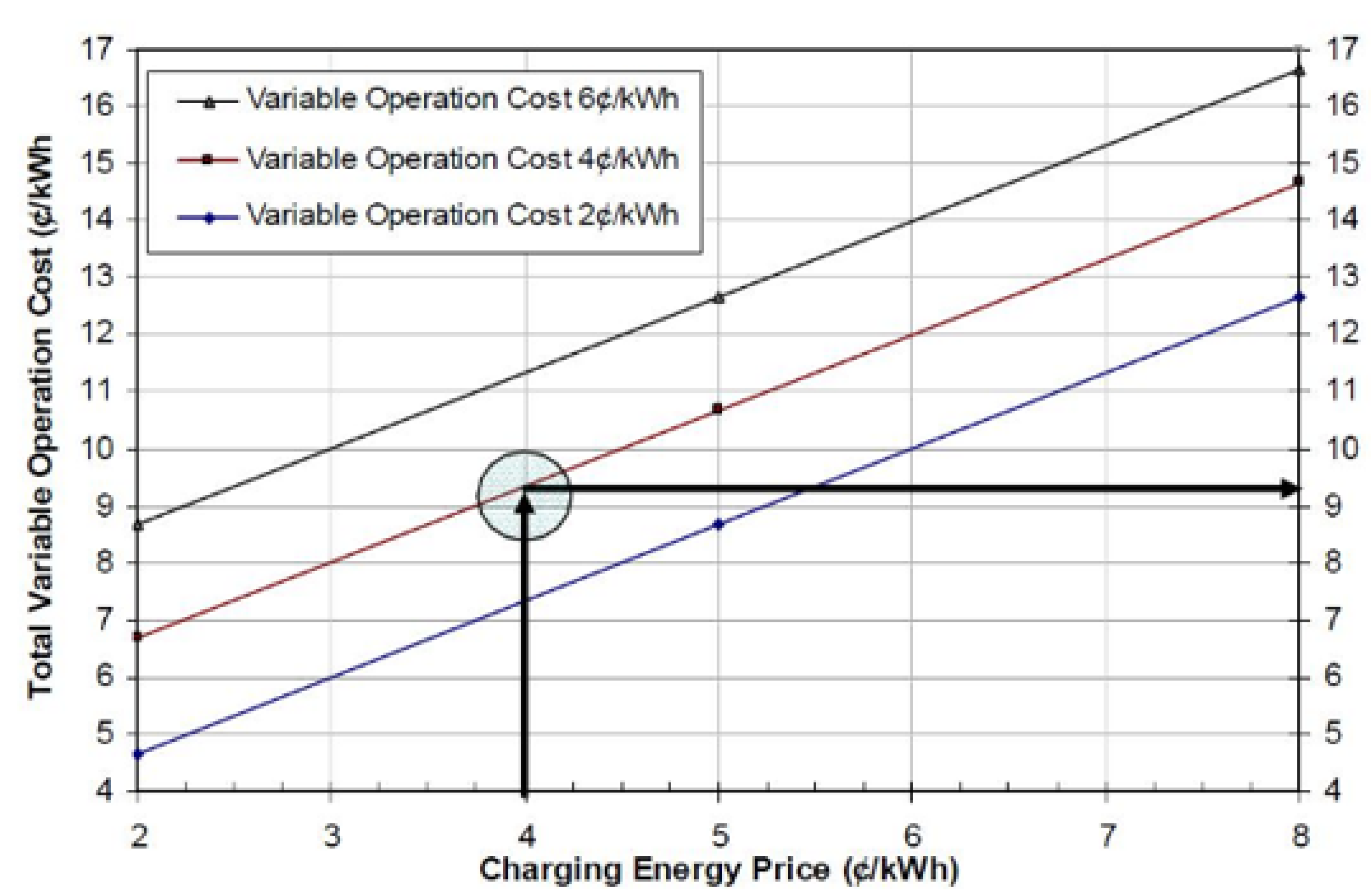
Figure 9.
Areas of application of the different Energy storage techniques [55].
Figure 9.
Areas of application of the different Energy storage techniques [55].
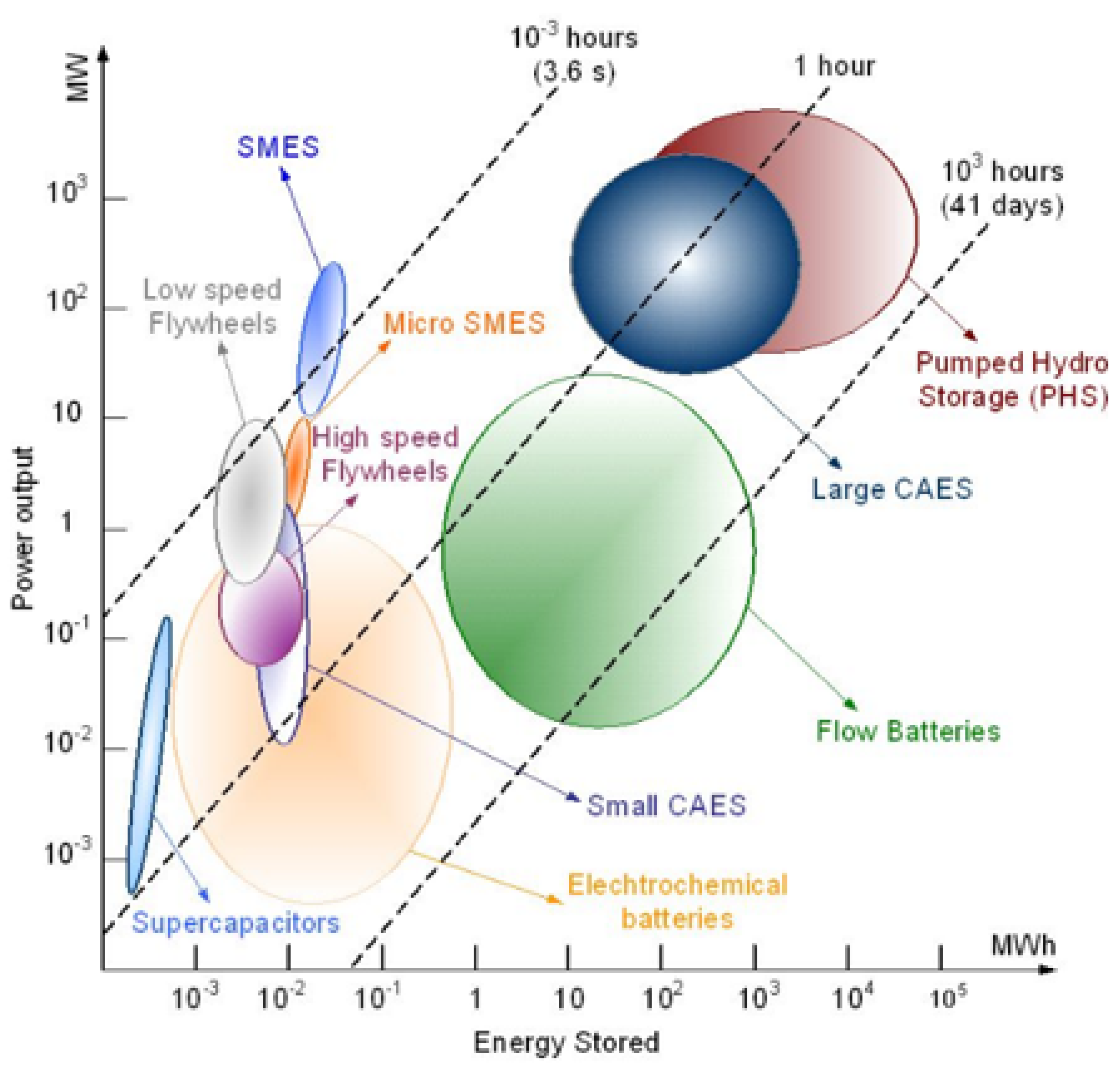
Figure 10.
Energy storage categorized based on its function.
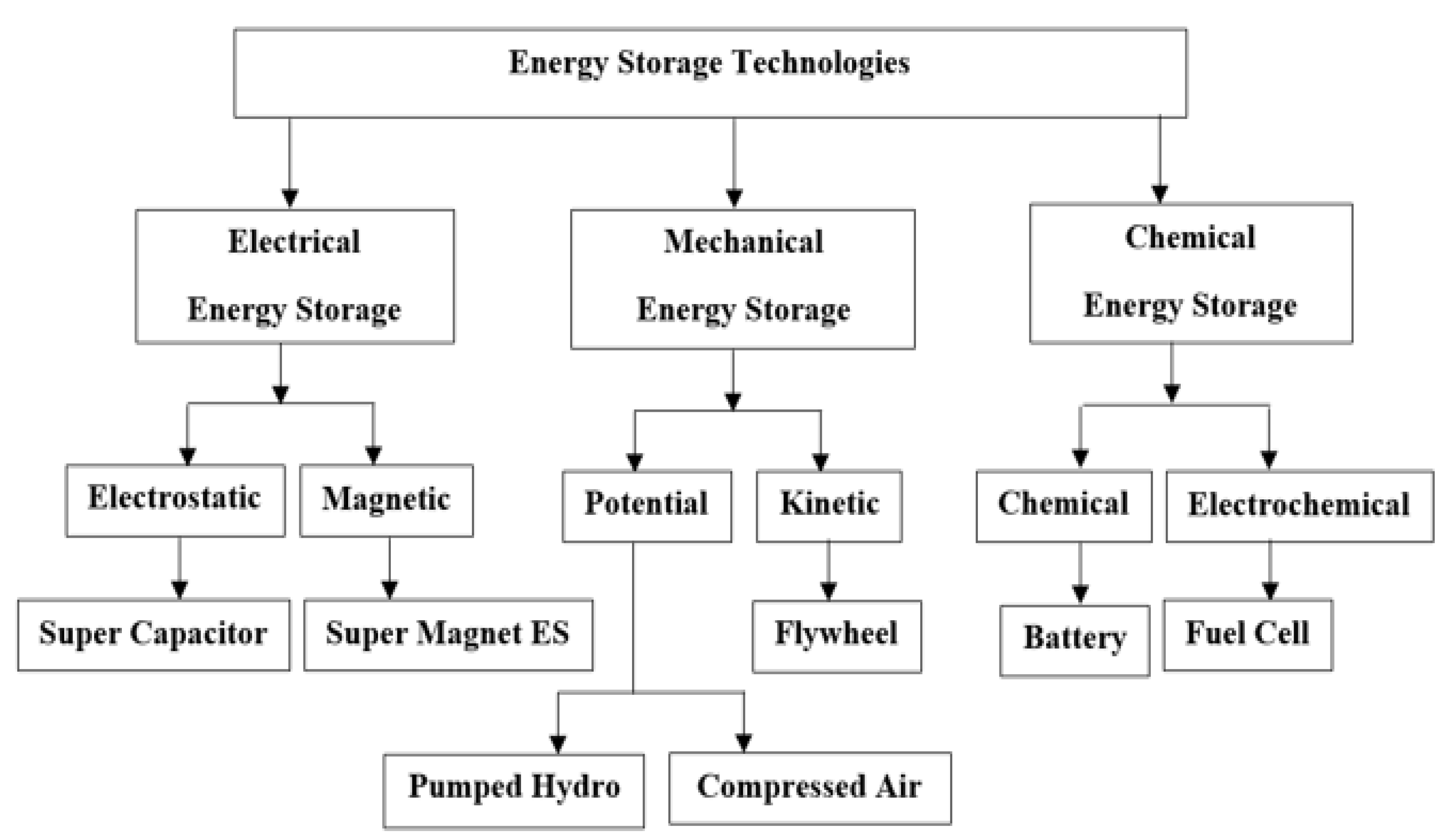
Figure 11.
An Example of Hybrid system Pumped hydro energy storage [44].
Figure 11.
An Example of Hybrid system Pumped hydro energy storage [44].
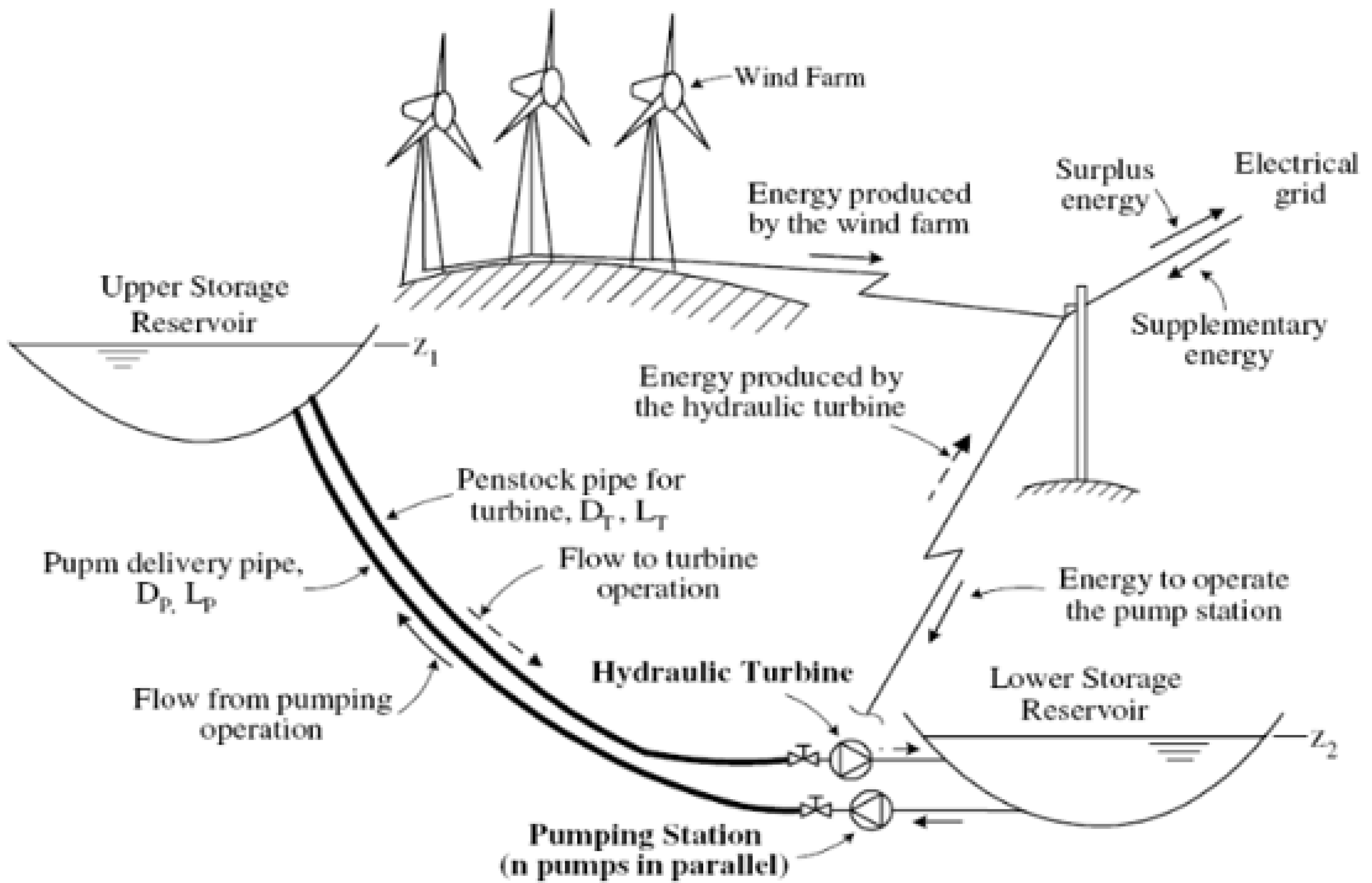
Figure 12.
Structure of flywheel energy storage system [56].
Figure 12.
Structure of flywheel energy storage system [56].
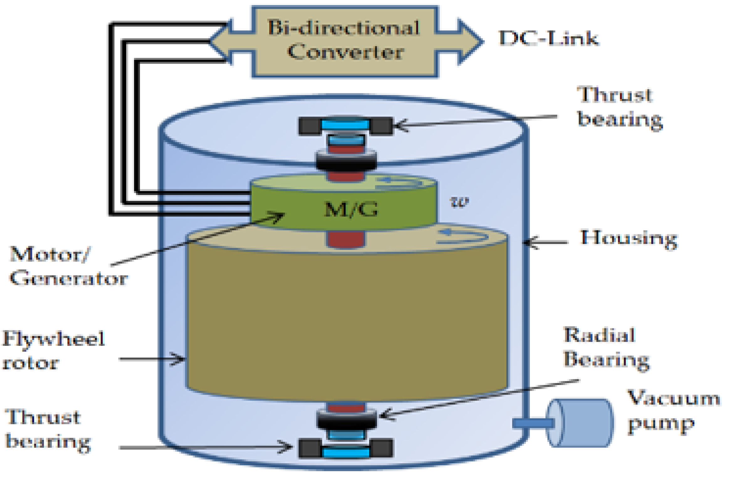
Figure 14.
Depiction of Compressed-Air Energy Storage Systems [69].
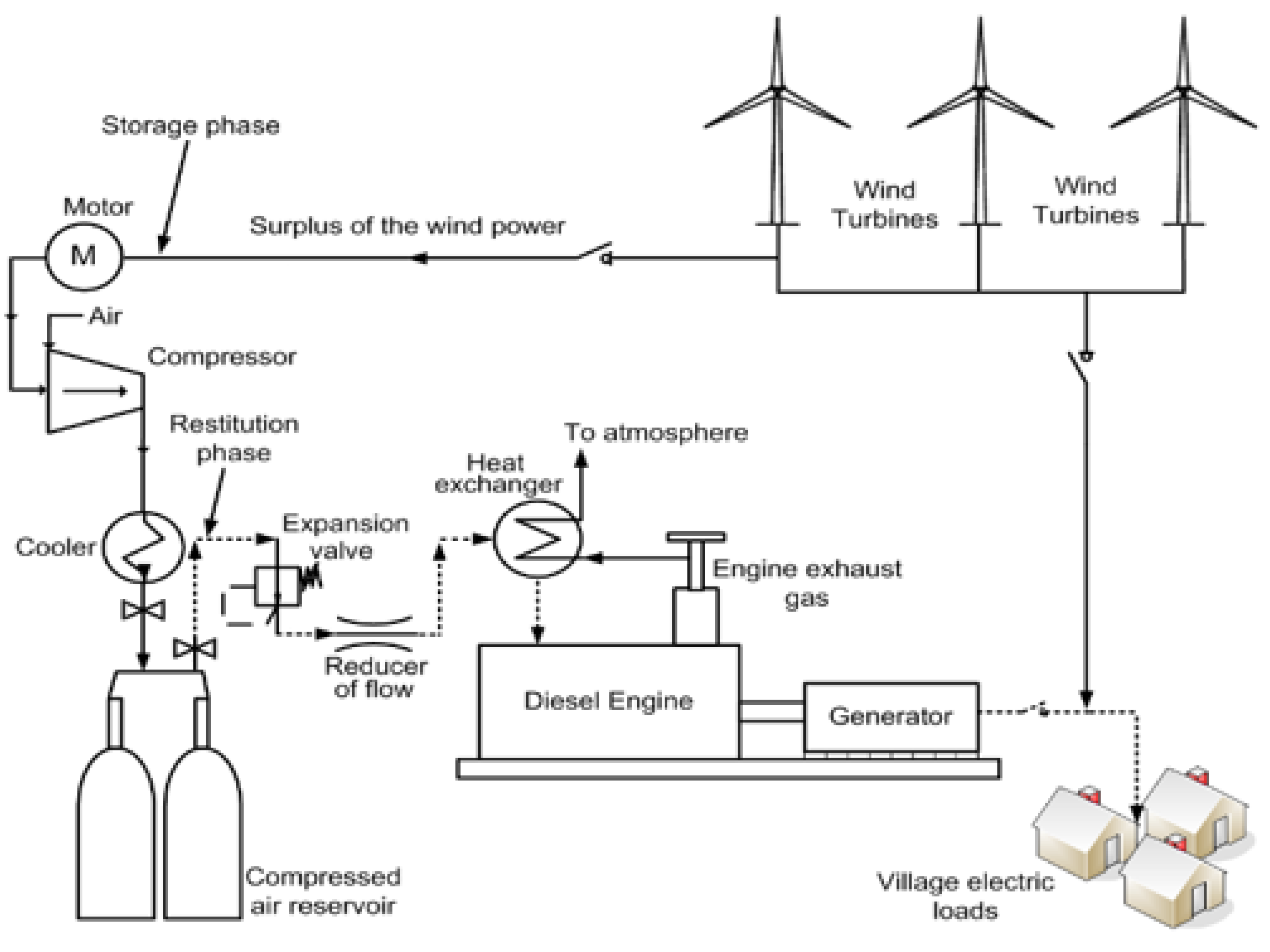
Figure 15.
The principle of the lithium-ion battery (LiB) [69].
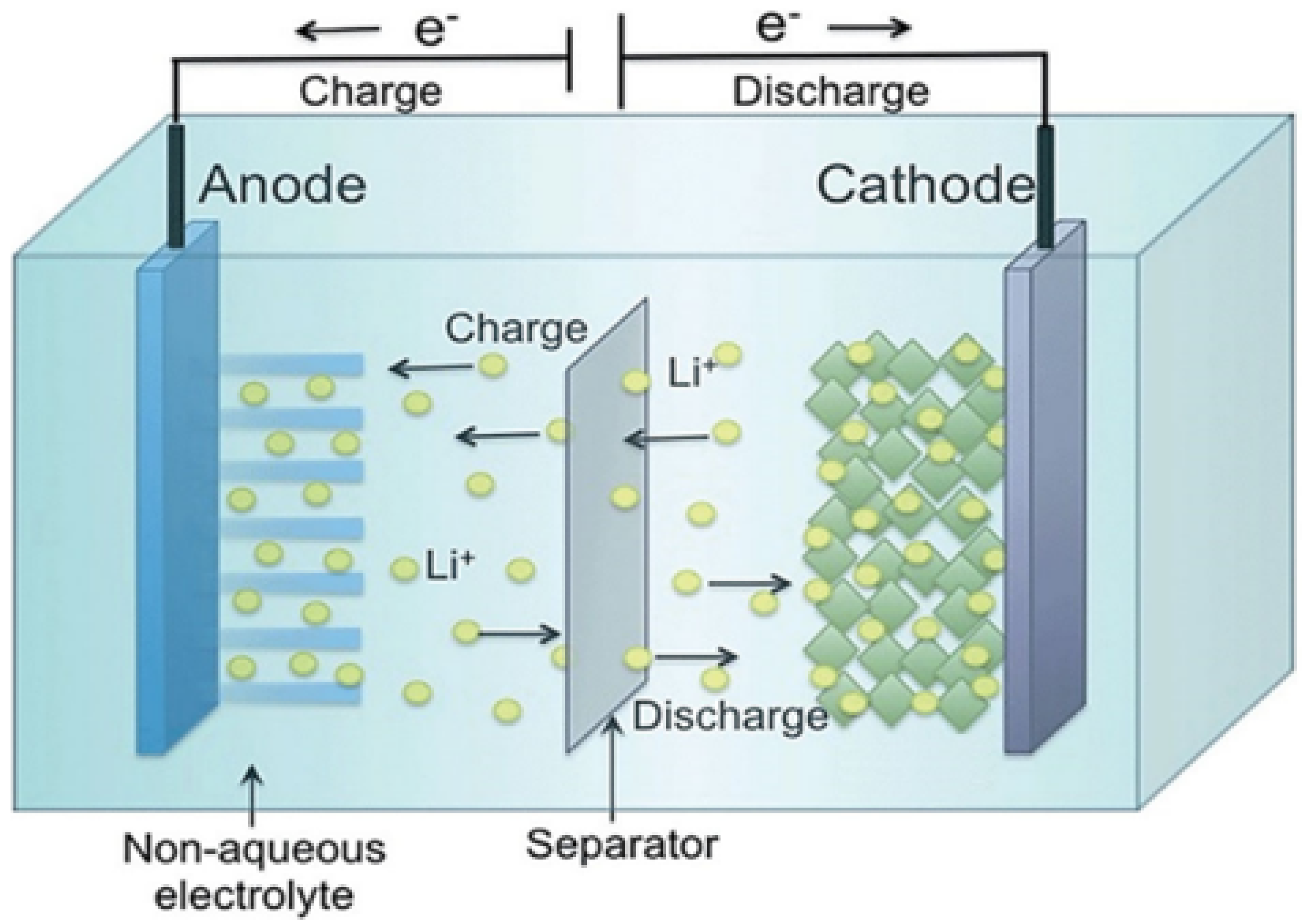
Disclaimer/Publisher’s Note: The statements, opinions and data contained in all publications are solely those of the individual author(s) and contributor(s) and not of MDPI and/or the editor(s). MDPI and/or the editor(s) disclaim responsibility for any injury to people or property resulting from any ideas, methods, instructions or products referred to in the content. |
© 2023 by the authors. Licensee MDPI, Basel, Switzerland. This article is an open access article distributed under the terms and conditions of the Creative Commons Attribution (CC BY) license (http://creativecommons.org/licenses/by/4.0/).
Copyright: This open access article is published under a Creative Commons CC BY 4.0 license, which permit the free download, distribution, and reuse, provided that the author and preprint are cited in any reuse.


