
Submitted:
16 August 2023
Posted:
17 August 2023
You are already at the latest version
Abstract
In crank presses, an important role is played by the presence of actuators with dwell, in which, with continuous movement of the input links, the output working link remains stationary at some part of the work. The use of a high-class structural group (fourth class) expands the functionality of the crank press, including it can ensure the link dwell of the working link on a given section of movement during the required period of time. As a result of the conducted research, four variants of actuators of the crank knee press were designed. Due to the rational choice of the positions of racks and crosshead guide, the best layout of the dimensions of the press mechanism has been achieved, changing the coordinates of the racks accordingly allows to design a mechanism with upper or lower dwells of the working links. When synthesizing (selecting) parameters such as: l_2 and h, it is possible to obtain a height of different duration. All this is shown on the basis of a numerical experiment based on kinematic analysis. In addition, the complex structure of the mechanism makes it possible to ensure the exact link dwell, which cannot be achieved due to the well-known knee presses based on the second-class mechanism [21].
Keywords:
Crank Knee press
; double-rod press
; high-class mechanisms
; output link dwell
; numerical experiment
; crank press design
1. Introduction and review of sources.
The study and expansion of the functional capabilities of crank-slide actuating mechanisms based on four-link structural groups is attractive for the development of new designs of crank presses and other stamping and forging machines [1,2]. They eliminate such disadvantages of existing crank presses as the distortion of the working slider in the process of forging compression and the limitations of the design for the implementation of the working slider dwells [1,3,4].
One of the most important characteristics of the press is the rigidity of its structural elements [1,5]. The rigidity of the press significantly affects the duration of the loading and unloading phases: the greater the rigidity of the links, the shorter the contact time, the rigidity of the press significantly affects the duration of the loading and unloading phases: the greater the rigidity of the links, the shorter the contact time of the stamp with the forging. This is especially important for increasing the stability of stamps in hot stamping processes [3,5]. However, an increase in the rigidity of the press structure leads to an increase in its metal consumption, which is not always economically feasible. So, for example, for a number of technological operations, in particular, to improve the quality of forging during cold stamping, it is desirable, on the contrary, to increase the duration of contact of the stamp with the workpiece [4].
Long-term contact of the stamp with the workpiece is ensured due to the operating link dwell. The four-link crank-slider mechanism cannot provide a long-term dwell of the working slider [1]. For this purpose, six-link mechanisms are used, which are obtained by layering a two-link group to a four-link crank-slider kinematic chain. Thus, a crank-knee mechanism is obtained, allowing the working slider dwell [7].
The crank-slider six-link mechanism is used as a feed mechanism for cutting a rubber with a circular saw [8]. In the work [9], crank press made of a single-circuit five-link linkage (2 DOF) with two degrees of freedom has a drive with an adjustable AC electric motor (CV). Dual-circuit hybrid crank presses with two degrees of freedom (2 DOF) are designed on the basis of seven-link lever mechanisms [10,11]. Hybrid presses use two engines, one of which "simulates" a CV-engine, prescribing a trajectory profile with a constant speed, the other allows to program the cyclogram of the technological process by controlling the servo motor.
In the works [12,13] a crank-slide double-rod mechanism of Stephenson II is proposed, which, in comparison with the existing operating mechanism of the crank press, has broader functionality. The structure of such mechanisms makes it possible to realize exact working link dwell [14].
In works [15], studies were conducted on the synthesis of hybrid mechanisms with five rods using genetic algorithms. A study was conducted [16] on modeling and kinematic analysis of a hybrid drive of a seven-stage mechanism with an adjustable crank. In work [17], a study was conducted using a hybrid machine (HM) system with a five-girder mechanism. In works [18], a configuration of seven rods was applied using kinematic analysis and optimal design of a hybrid system. [19] A seven-stage mechanism was presented , which was later used to study the efficiency of stamping and energy distribution between a servo motor and a flywheel with different motion inputs. In addition, [20] has also developed control system for seven-stage mechanism using iterative learning management and feedback control methods.
2. Materials and Methods
2.1. Kinematic analysis
The kinematic scheme of a two-rod crank knee press with an internal engine arrangement is shown in Figure 1. The mechanism under consideration has the following design features: ; b) link 4 makes a forward motion [1], therefore also there is . Another feature of this mechanism structure is that the coordinates of the frame lies on the straight line of the stroke of the working slider 7.
Based on the kinematic scheme of the mechanism, we write down the equations in vector form
We introduce the following labeling
Taking into account the adopted labelings, the projections of equations (1) on the coordinate axes are written as:
System (2) will be written in the following form
where
In the mechanism under consideration, the variable kinematic parameters are- . It is assumed that the engine will be connected to link 1 and mounted on the frame . Hence, the angular coordinate of the input link is taken as the generalized coordinate 1 - . The mechanism belongs to the fourth class according to the classification of I.I. Artobolevsky [7], since the driven kinematic chain contains a four-sided closed loop and the structural group (2,3,4,5,6,7) does not break up into groups of a smaller order.
At the same time, the analysis of the positions of the mechanism for a given , i.e. system (3) has no analytical solutions. From the analysis of system (3), it can be seen that the first three equations of system (3) relative to - represent a system of nonlinear trigonometric equations, which should be solved by approximate numerical methods. Then, from the last equation of system (3), the coordinate of the slider is determined 7 -
To construct an effective numerical algorithm for the kinematic analysis of the mechanism under consideration, we apply the following approach.
Based on system (3), we write the e the kinematics equations of the mechanism in small displacements [2] with respect to relatively in the form of a matrix equation (3×3):
where
and
The solution to system (5) has the form
where
A technique, allows to establish special positions of the mechanism based on the analysis of the functional from equation is proposed (8):
Let’s consider a trivial solution to equation (9) with geometric interpretation. Below are the options for these solutions:
A) let , then equation (9) is fulfilled in two options: 1) or (and) 2) . In the first option, we have when result ; in the second option, when we have . The first option is interpreted as follows: the link and the links occupy mutually parallel positions, in the second case, links and are parallel.
B) let , hence there is a which happens when links and are parallel. For a trivial solution to equation (9), one of two variants must also be fulfilled here: 3) or (and) 4) . In the third version the links occupy a perpendicular position relative to the slide stroke, in the fourth version the links and are parallel.
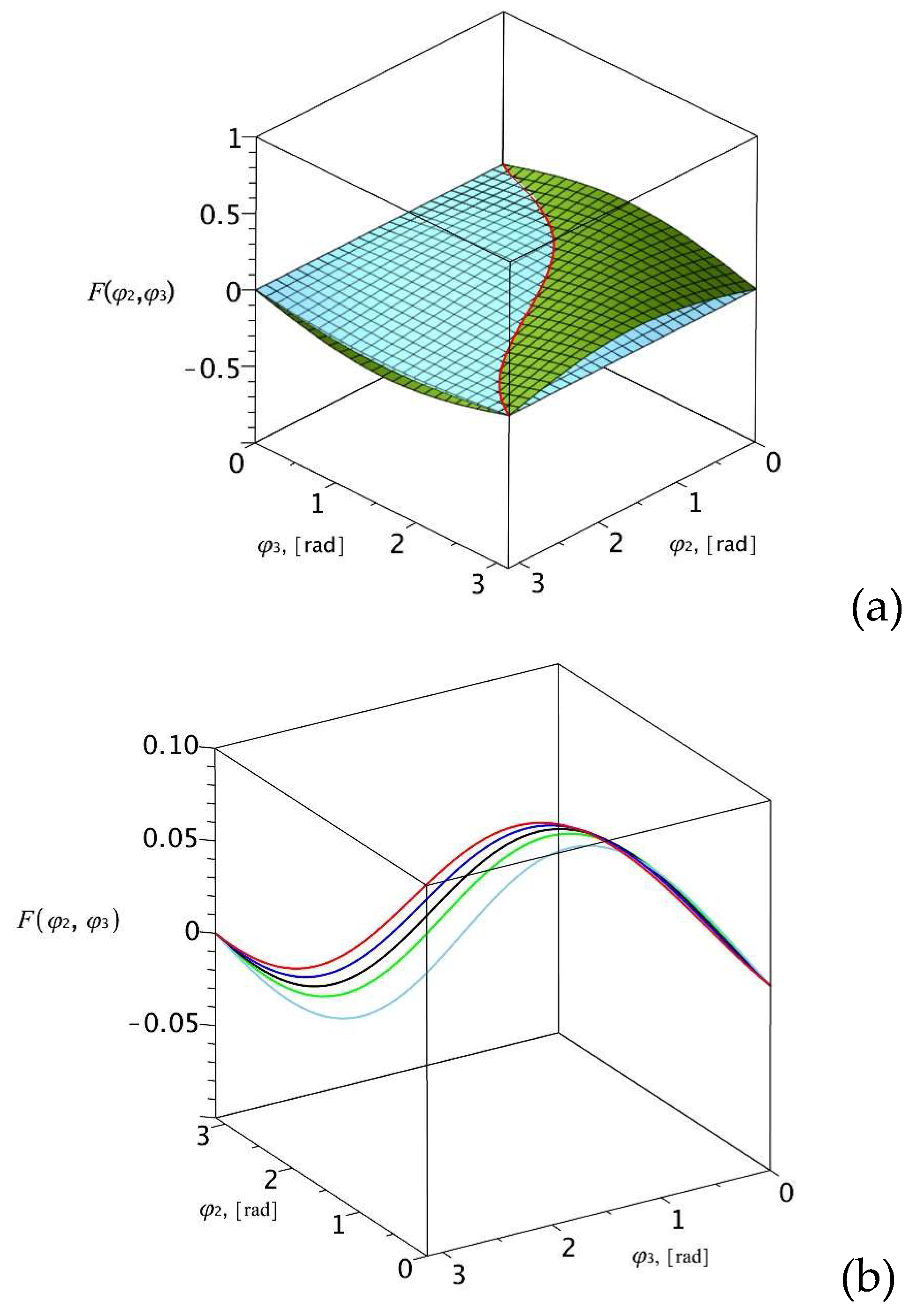
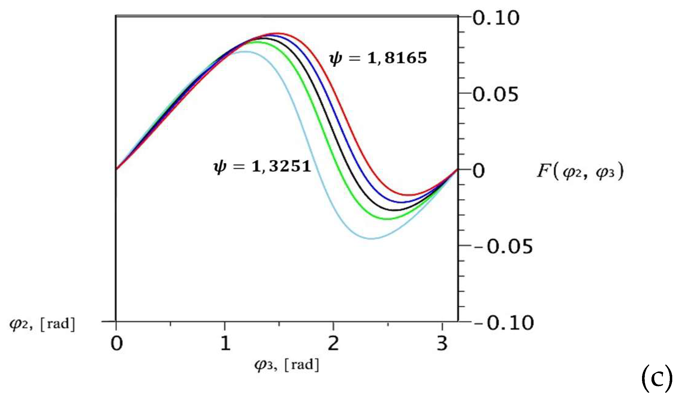
In order to visualize the functional (9) in a three-dimensional system, a fixed value of one the parameters should be set. Such parameter is ψ, which has the following domain of variability , where r - crank length, l- rod length BC.
Thus, the functional is presented at following values in the system of coordinates .
Figure 2(a) shows the functional , that is, with a fixed ψ=1.8165 as the intersection of two functions and . Further were built at other values , which are shown in Figure 2(b) in the form of intersection curves of these two surfaces. In Figure 2(c) the intersection curves projected on a plane .
Figure 2.
Functional graphs in the three-dimensional system .
The solution of system (5) is correct only in a certain assembly of the mechanism when the condition is met (8). Therefore, from the beginning it is necessary to select the assembly of the mechanism, and as a consequence, to set the initial values of the variable parameters on which the continuous movement of the mechanism is possible. The problem of determining the assembly and the initial position of the mechanism, is solved by replacing the leading link [3], i.e. by choosing another variable as a generalized coordinate, which makes it possible to simplify the solution of the original system (2). This variable is called - conditional generalized coordinate (CGC) [4].
The analysis of system (2) shows that it is advisable to take as CGC the angular coordinate . Considering this, the system (2) can be represented as:
where .
At a given coordinate solutions of system (10) with respect to are represented as the following decisive algorithm 1:
- [1]
- Constant parameters are set and calculated: ;
- [2]
- ;
- [3]
- [4]
- [5]
- [6]
- [7]
Thus, on the basis of the algorithm, assembly options and the choice of the desired assembly are established, the initial positions of the mechanism are determined at , then at a given are defined
Here, based on system (7)
The stroke of the slider is determined by the formula
3. Numerical experiment and discussion of results.
Based on the above algorithm, a program for numerical modeling of the kinematic analysis of the mechanism has been comprised. It is assumed that link 1 (crank) performs full rotation, link 3 (rocker) performs a hobbing motion. Four types of mechanisms of given structure of the knee press were considered (Figure 1):
At the same time , the values of the following links of the driven chain of the mechanism will remain unchanged: Remaining parameters: - take different values for the corresponding types of the mechanism (Figure 2).
Figure 3.
Assemblies of knee press mechanisms (13), corresponding to four types of its structure.
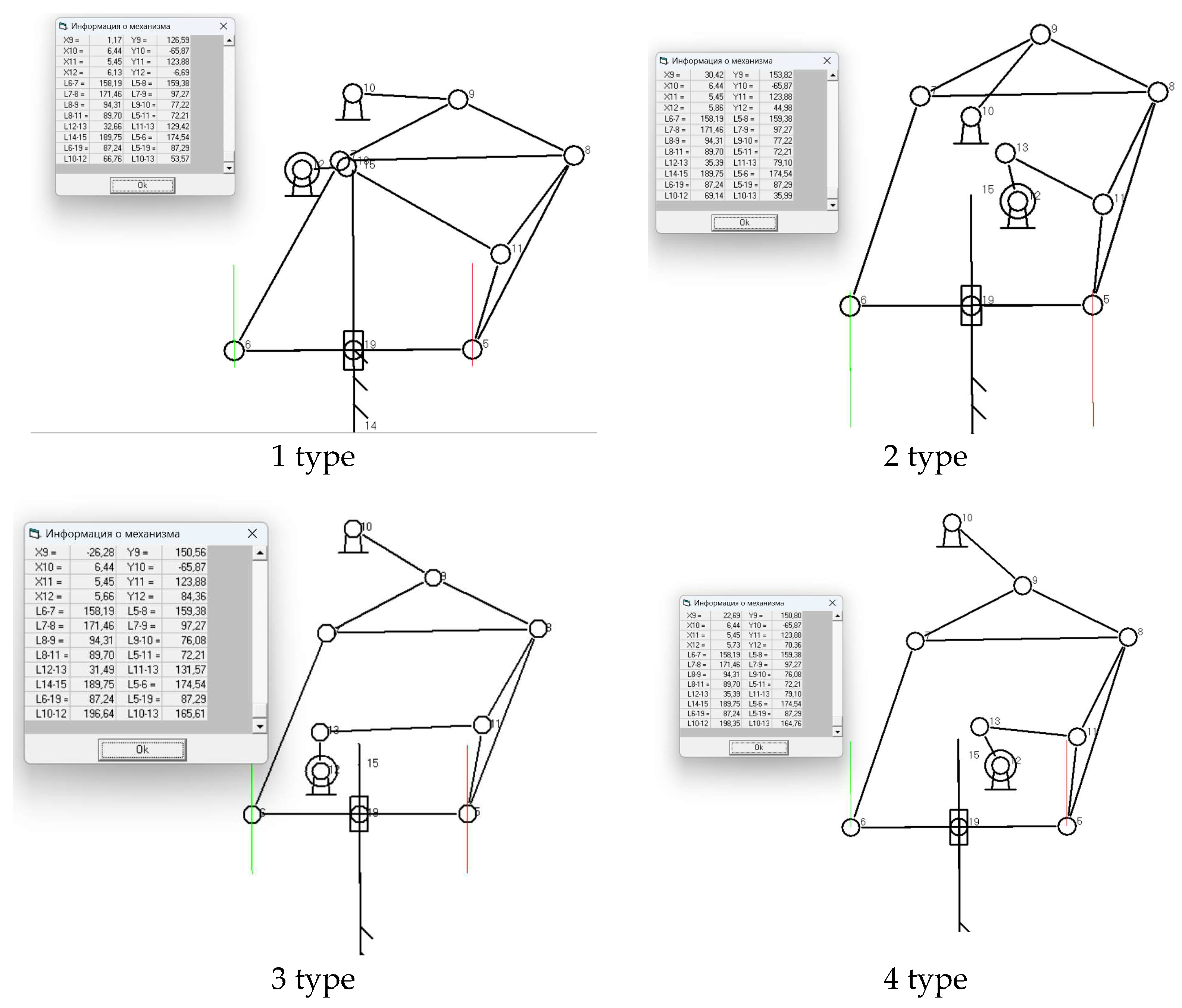
Figure 4 shows the results of the kinematic analysis of the first type of the knee press mechanism. The varying parameters are equal: . The angular velocity of the input link is equal , then the time of one cycle is The slider stroke is . Output link 7 (slider) remains stationary for a long time . i.e. the slider performs almost one third of the working cycle Figure 4(a). Figure 4(b) shows graphs of the velocity and acceleration of the interrelationship with the graph of the position function. By definition, dwell occurs when one or more consecutive derivatives of the position functions of the output link simultaneously vanishes. From Figure 4(b), it can be seen that during dwell, the velocity and acceleration remain close to zero.
Figure 5 shows the results of the kinematic analysis of the second type of the knee press mechanism. The variable parameters are equal: . In this case, the slider stroke is . The output link 7 (slider) remains motionless . Figure 5 (b). At the same time, the slider 7 performs fast working stroke in . and the acceleration changes rapidly within , that is, there is a blow.
In the considered options, when , there is a slider dwell in its upper position. At the same time, the slider dwell . at significantly more than the dwell . at .
Figure 6 shows the results of the kinematic analysis of the third option of the knee press mechanism. The variable parameters are equal: In this case, the dwell of the working slider occurs in the lower position, when there is direct contact with the workpiece, and the slider stroke is . The output link 7 (slider) remains stationary . Figure 6(a), which amounts 1/3 T - total working cycle time. In some crank presses, there are requirements when it is necessary to ensure rapid compression of the forging and a long reverse of slide stroke [4,6]. Such a process can be provided by this structure of the crank press mechanism. In Figure 6(a) it can be seen that the forging compression time reverse time . From Figure 6(b) it can be seen that during the dwell, the velocity and accelerations remain close to zero.
Figure 7 shows the results of the kinematic analysis of the fourth option of the knee press mechanism. The variable parameters are equal: . In this case, the dwell of the working slider also occurs in the lower position and the slider stroke is , which is the same with the dwell of the working link in the third option. The output link 7 (slider) remains stationary Figure 7 (a), which represents 1/6 T - total working cycle time. This version of the mechanism also provides rapid compression of the forging and a long reverse motion. In Figure 6(a) it can be seen that the forging compression time is reverse motion time . From Figure 7(b) it can be seen during the dwell, the velocity and accelerations remain close to zero, i.e. there is an approximate working link dwell.
Figure 8 shows the results of a kinematic analysis of the third option of the knee press mechanism by the angular positions of the links. From the analysis of the graphs, it can be seen that the triangular link 4 makes a translational movement, since the angular coordinate is constant. The angular coordinates of links 5 and 6 (pink) and link 2 (orange) change. The angular coordinate of the crank 1 is marked in yellow. Similarly, the angular coordinates of the links of the mechanisms in other versions of the crank press change.
4. Conclusions
In crank presses, an important role is played by the presence of actuators with dwell, in which, with continuous movement of the input links in a certain section, the output working link remains stationary. The use of a high-class structural group (fourth class) expands the functionality of the crank press, including the ability to ensure the working link dwell in a given area of movement and a period of time. As a result of the conducted research, four options of the actuators of the crank knee press were designed. Due to the rational choice of the positions of the frames and the slider guide, the best layout of the dimensions of the press mechanism has been achieved, changing the coordinates of the frame allows you to design a mechanism with upper or lower working link dwells. When synthesizing (selecting) parameters such as: and , it is possible to obtain dwell of different duration. In addition, the complex structure of the mechanism makes it possible to ensure the exact dwell of the link, which cannot be achieved due to the well-known knee presses based on the second-class mechanism [21].
Author Contributions
A.T. concept development; B.I. holding research; M.K. holding statistical analysis; B.M. preparing and editing text; G.I. creating software.
Funding
The work was carried out within the framework of the grant project AP14972874 funded by the Science Committee of the Ministry and Higher Education of the Republic of Kazakhstan.
Institutional Review Board Statement
Not applicable.
Informed Consent Statement
Not applicable.
Data Availability Statement
Data are contained within the article.
Conflicts of Interest
The authors declare no conflict of interest.
References
- Evgrafov, M.; Semyonov, Yu.; Sloushch, A. Theory of mechanisms and machines: study guide. - M.: Publishing Center "Academy", 2006.- 560 p.
- Bocharov, Yu. Forging and stamping equipment. - М.: Publishing Center "Academy", 2008. – 480 p.
- Matthews, S.; Tanninen, P.; Toghyani, A.; Eskelinen, H.; Ovaska, S.-S.; Leminen, V.; Varis, J. Novel method for Selection of Drive Motor in Paperboard Forming Press Utilizing Multi-Dynamics Model based on Material Thickness//27th International Conference on Flexible Automation and Intelligent Manufacturing, FAIM2017, 27-, Sami Matthews et al. /Procedia Manufacturing 11 (2017) 2091 – 2098, Modena, Italy. 30 June.
- Chen, Y.; Sun, Y.; Yang, D. Investigations on the dynamic characteristics of a planar slider-crank mechanism for a high-speed press system that considers joint clearance// Journal of Mechanical Science and Technology 31 (1) (2017) 75~85.
- Telegin, I.; Shumilova, T. Comparing the efficiency of flowsheets for hot die forging on crank presses// MATEC Web of Conferences 224, 01092 (2018). ICMTMTE 2018.
- Tuleshov, A.; Drakunov, Yu. and etc. Crank Lever Presses Based on the Stephenson Mechanism II: Monograph, ISBN978-601-332-973-4, Almaty, 2020.-240 p.
- Moldabekov, M.; Tuleshov, A.; Ualiev, G. Mathematical modeling of the dynamics of mechanisms and machines. - Almaty: Kazak University, 1998. - 204 p.
- Shihao, Liu.; Mao, Lin. 9: Design and test of the crank slider mechanism feeding type rubber rotary cutting machine// Springer Nature Switzerland AG 2020 2, 2020. [CrossRef]
- Ouyang, P.; Li, Q.; Zhang, W. Design, modelling and control of a hybrid machine system, Mechatronics 14 (2004) 1197–1217.
- Yuan, Z.; Gilmartin, M.; Douglas, S. Design of hybrid machines for nonuniform motion production, Proc. Inst. Mech. Eng. C 219 (2005) 491–499.
- Kutuk, M.; Dulger, L. A hybrid press system: Motion design and inverse kinematics issues/Engineering Science and Technology an International Journal, 2016. P.846-856.
- Tuleshov, A.; Jamalov, N.; Jomartov, A. and etc. Patent of the Republic of Kazakhstan for invention No. 33874. Crank-slide mechanism of the press. applicant. and patent holder JIME named after Dzholdasbekov, U. - No. 2018/0225.1 dated 04/10/2018; publ. 09/06/2019, bul.
- Jamalov, N.; Tuleshov, A.; Jomartov, A.; Seidakhmet, A.; Kamal, A. Eurasian patent for invention No. 038760. Crank-knee press mechanism. Applicant and patent holder of the Dzholdasbekov U. JIME dated 10/15/2021 (Derwent Innovations Index).
- Tuleshov, A.; Halicioglu, R.; Shadymanova, A. and Kuatova, M. Kinematic synthesis method and eccentricity effects of a Stephenson mechanism, Mech. Sci., 12, 1-8, 2021.
- Connor, A.; Douglas, S. and Gilmartin, M. The synthesis of hybrid five-bar path generating mechanisms using genetic algorithms, 1st International Conference on Genetic Algorithms in Engineering Systems: Innovations and Applications, 313–318, Galesia, 1995.
- Dülger, L.; Kireçci, A. and Topalbekiroglu, M. Modeling and simulation of a hybrid actuator, Mech. Mach. Theory, 38, 395– 407, 2003.
- Yu, H. 3. [CrossRef]
- Li, H. and Zhang, Y. Seven bar mechanical press with hybrid driven mechanism for deep drawing; part 1: kinematics analysis and optimum design, part 2: dynamic modeling and simulation, J. Mech. Sci. Technol., 11, 2153–2160, 2161–2167, 2010. [Google Scholar]
- Li, H. and Tso, P. L.: Experimental study on a hybrid driven press using iterative learning control, International Journal of Machine Tools and Manufacture, 48, 209–219, 2008.
- Tso, P. L. : Optimal Design of a Hybrid-Driven Servo Press and Experimental Verification, J. Mech. 0345; 03. [Google Scholar] [CrossRef]
- Yan, H. S. and Chen, W. R. "A variable input speed approach for improving the output motion characteristics of Watt-type presses," International Journal of Machine Tools and Manufacture, vol. 40(5), pp. 675-690, 2000.
Figure 1.
Kinematic diagram of a two-rod crank knee press with an internal engine location.
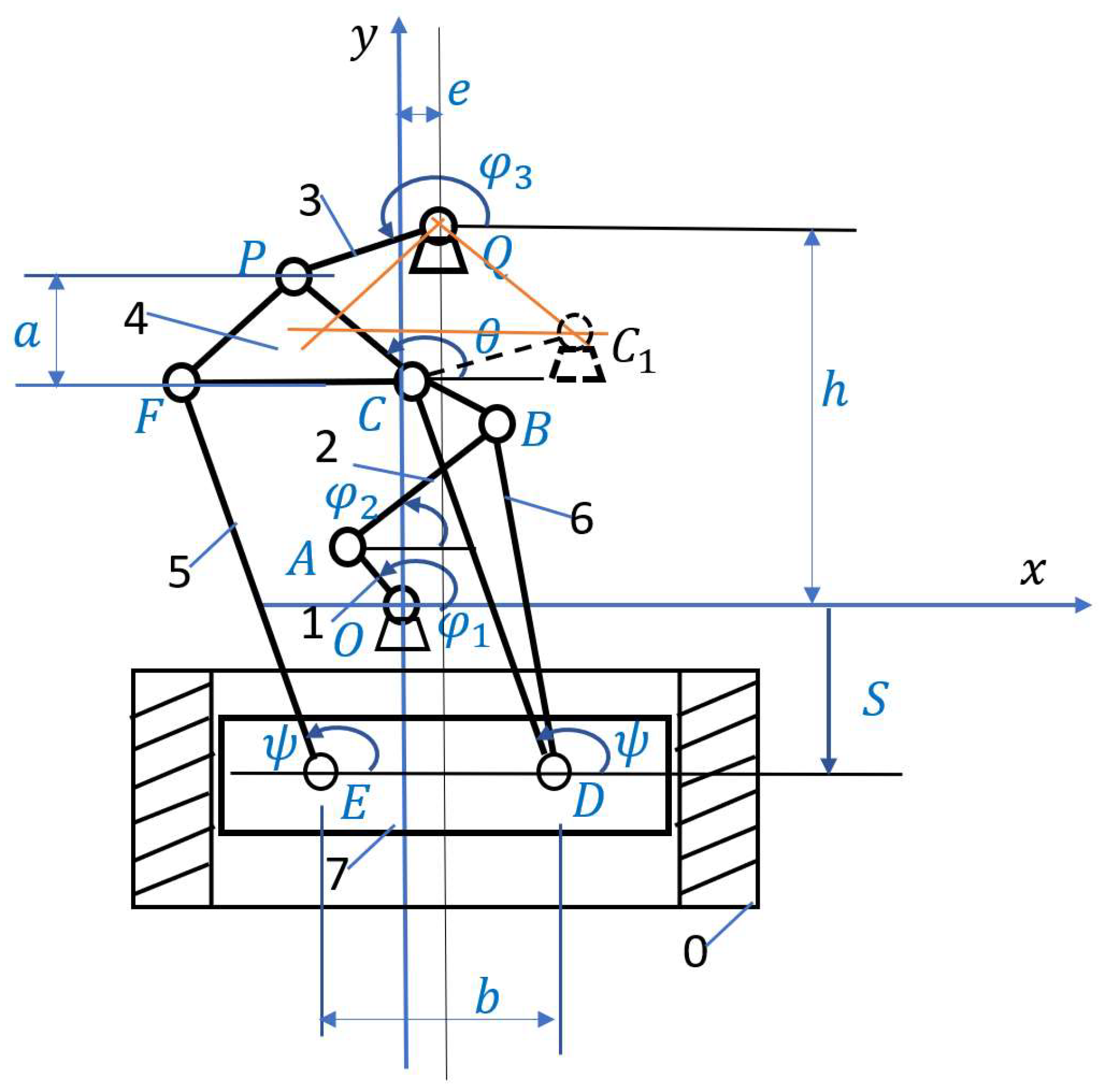
Figure 4.
Results of the kinematic analysis of the first type of the knee press mechanism: a) graph of the function of the position output link (slider); b) graphs of the speed and acceleration of the slider.
Figure 4.
Results of the kinematic analysis of the first type of the knee press mechanism: a) graph of the function of the position output link (slider); b) graphs of the speed and acceleration of the slider.
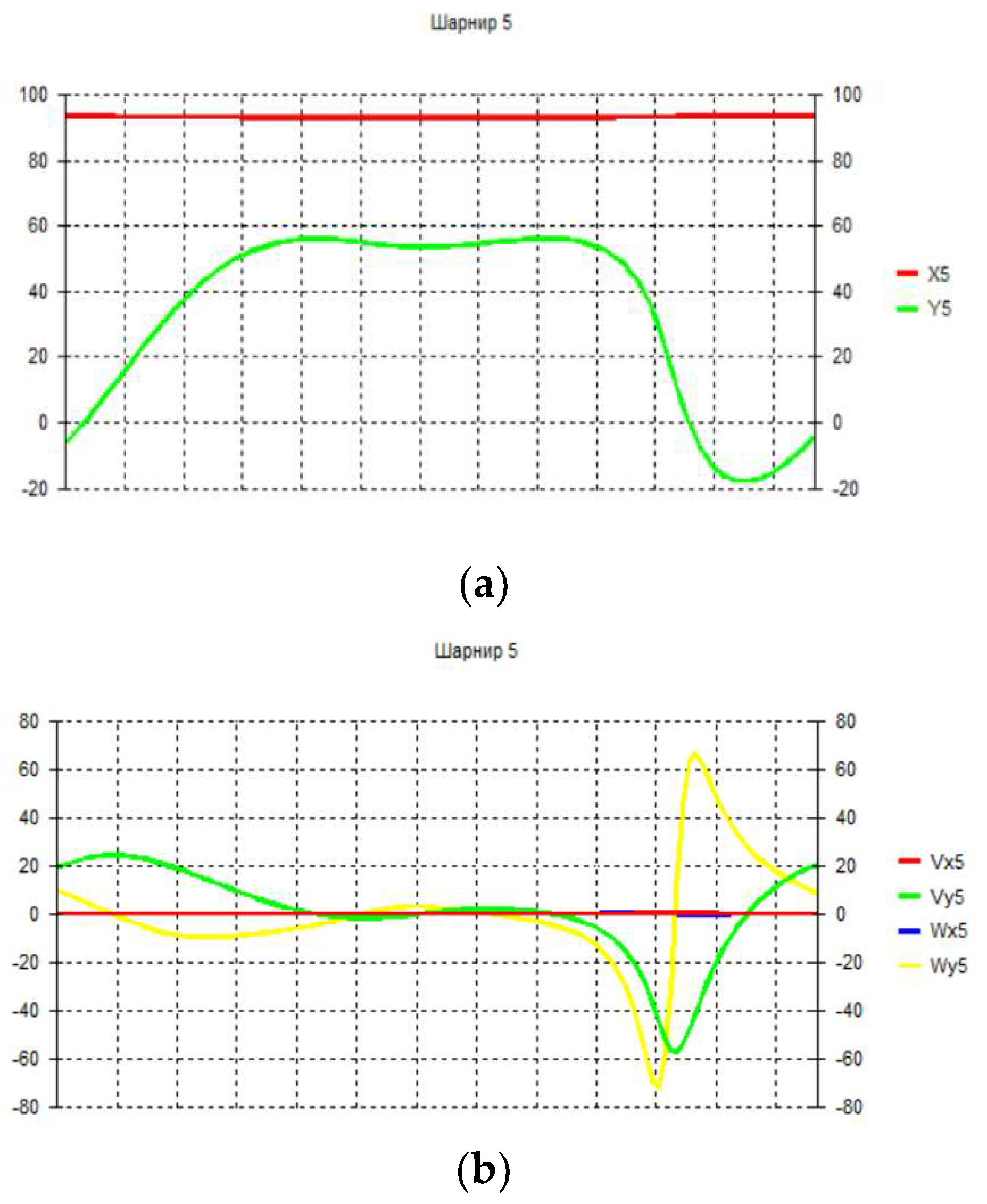
Figure 5.
Results of the kinematic analysis of the second type of the knee press mechanism: (a) graph of the function of the position of the output link (slider); (b) graphs of the position, speed and acceleration of the slider.
Figure 5.
Results of the kinematic analysis of the second type of the knee press mechanism: (a) graph of the function of the position of the output link (slider); (b) graphs of the position, speed and acceleration of the slider.
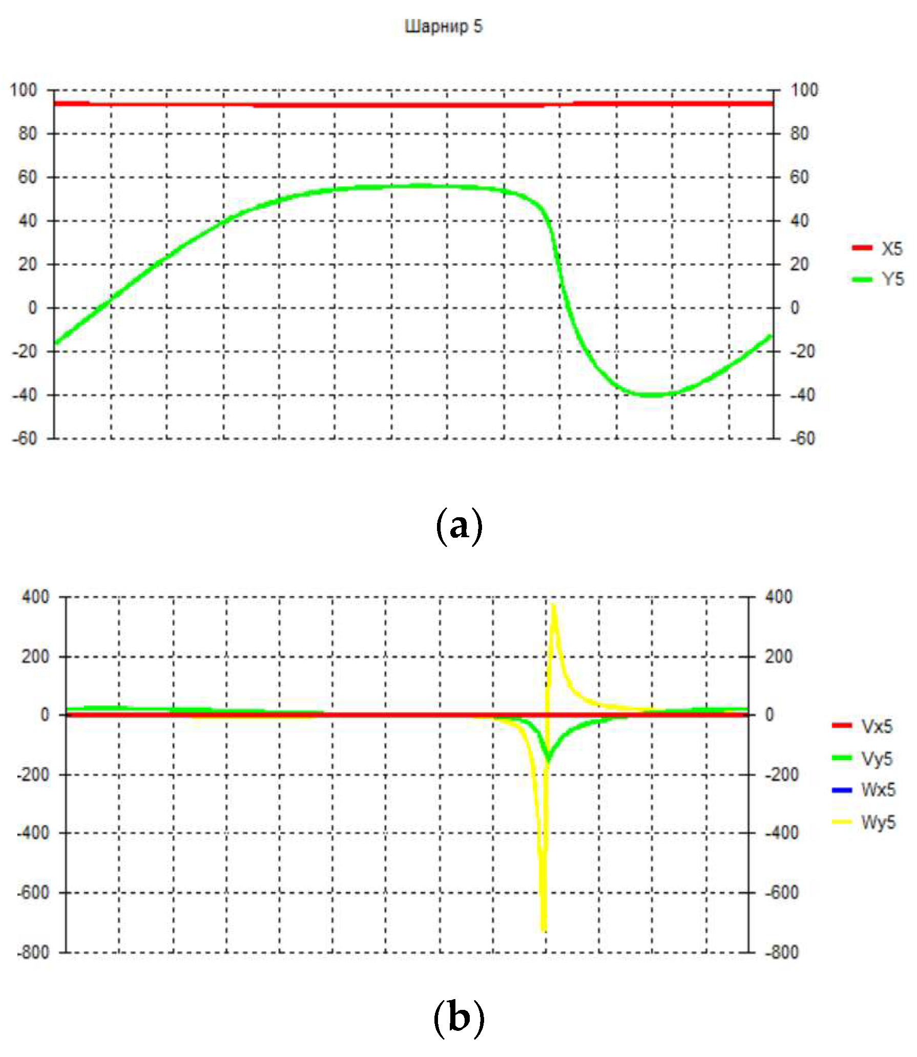
Figure 6.
Results of the kinematic analysis of the third option of the knee press mechanism: (a) graph of the function of the position of the output link (slider); (b) graphs of the position, speed and acceleration of the slider.
Figure 6.
Results of the kinematic analysis of the third option of the knee press mechanism: (a) graph of the function of the position of the output link (slider); (b) graphs of the position, speed and acceleration of the slider.
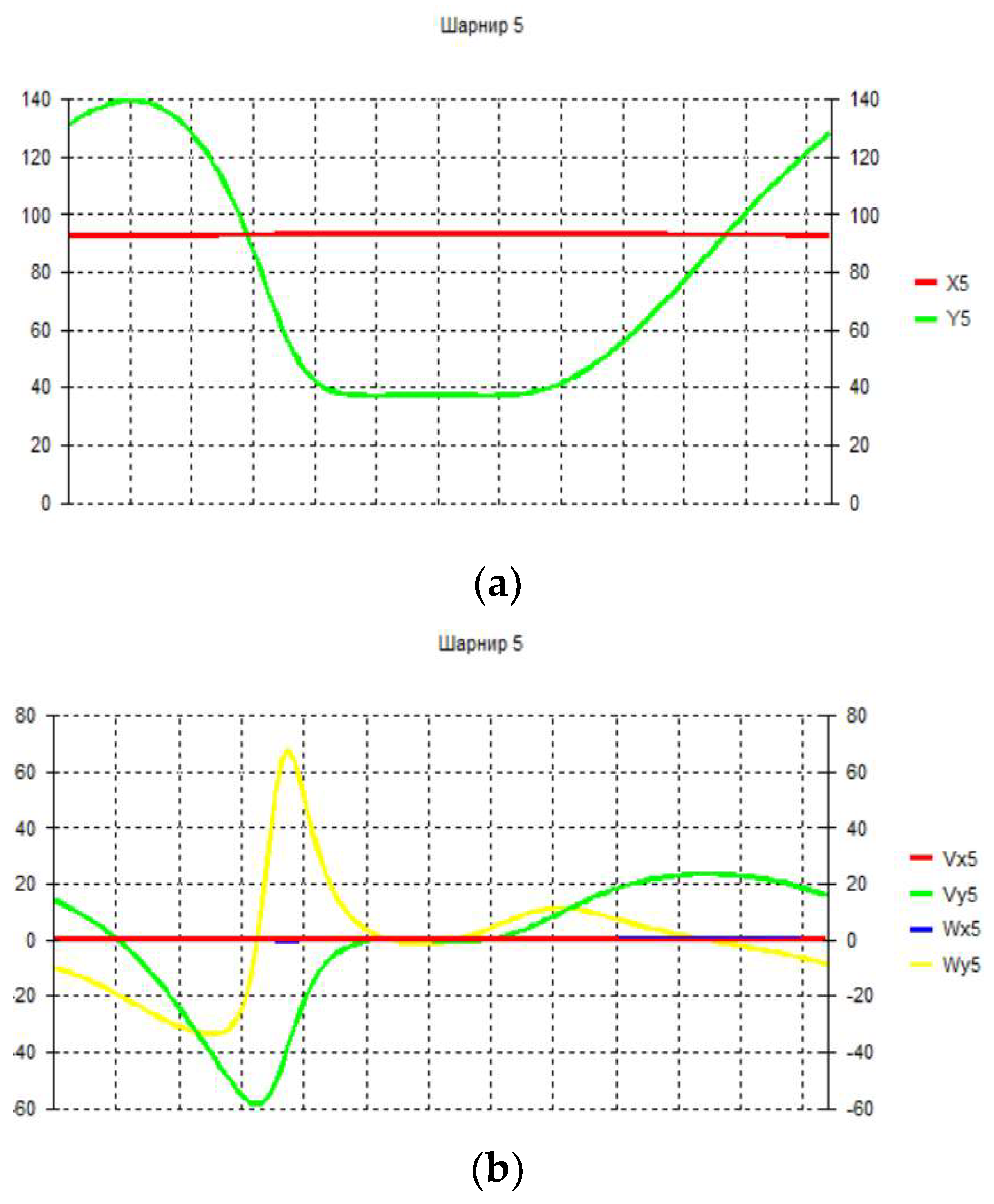
Figure 7.
Results of kinematic analysis of the fourth option of the knee press mechanism: (a) a graph of the function of the position of the output link (slider); (b) graphs of the position, speed and acceleration of the slider.
Figure 7.
Results of kinematic analysis of the fourth option of the knee press mechanism: (a) a graph of the function of the position of the output link (slider); (b) graphs of the position, speed and acceleration of the slider.
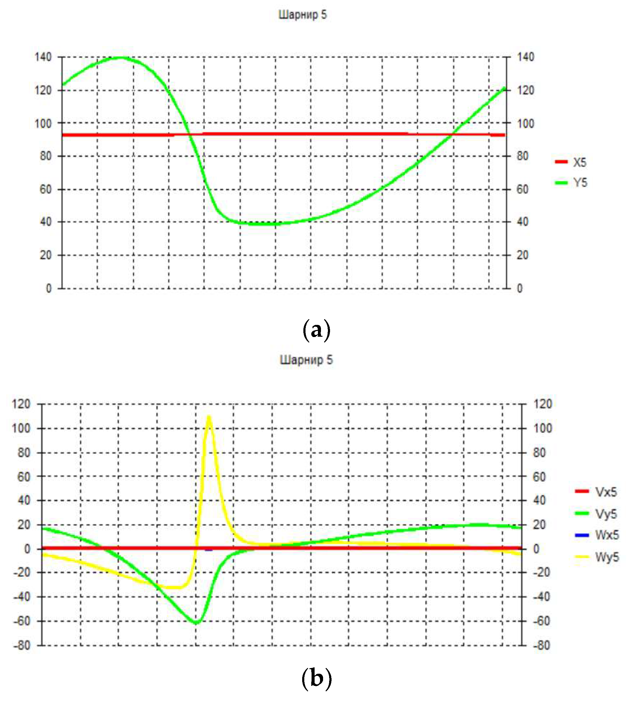
Figure 8.
Results of kinematic analysis of the third option of the knee press mechanism by the angular positions of the links.
Figure 8.
Results of kinematic analysis of the third option of the knee press mechanism by the angular positions of the links.

Disclaimer/Publisher’s Note: The statements, opinions and data contained in all publications are solely those of the individual author(s) and contributor(s) and not of MDPI and/or the editor(s). MDPI and/or the editor(s) disclaim responsibility for any injury to people or property resulting from any ideas, methods, instructions or products referred to in the content. |
© 2023 by the authors. Licensee MDPI, Basel, Switzerland. This article is an open access article distributed under the terms and conditions of the Creative Commons Attribution (CC BY) license (http://creativecommons.org/licenses/by/4.0/).
Copyright: This open access article is published under a Creative Commons CC BY 4.0 license, which permit the free download, distribution, and reuse, provided that the author and preprint are cited in any reuse.


