
Submitted:
03 August 2023
Posted:
04 August 2023
You are already at the latest version
Abstract
Researches are moving to iron and ammonia elimination from ground water. Here, we are using poly acrylic–poly acrylamide hydrogel which grafted with 3-chloroaniline. This copolymer was synthesized by addition polymerization. Effect of agitation time, dosage and adsorbents temperature on the removal process sensitivity has been investigated. The copolymer was described experientially and theoretically. Isothermal, kinetic adsorption models and were discussed. This hydrogel could be regenerated efficiently (98.3%removal of iron and 100% removal of ammonia). Density functional theory DFT method using B3LYP/6-311G(d,p),LANL2DZ level of the theory were managed to investigate stationary states of grafted co-polymer and the complexation energy of the hydrogel with the studied cations. NBO analysis is using DFT to investigate the negative centers on the hydrogel. The complexation energy showed selectively of hydrogel to studied cations.
Keywords:
Grafted hydrogel
; Ground water
; Ammonia and Iron removal efficiency
; DFT and MEP
; binding Energy
1. Introduction
Groundwater is a one of the world’s drinking water primary sources. Iron and ammonia are present in groundwater in dissolvable reduced state due to both natural, chemical environment and human activities [1,2,3]. Metal ions in water resources causes a variety of aesthetic and operational issues, including repulsive unpleasant taste, laundry stains, and network accumulation [4,5,6,7] are caused issues by ammonia in ground water. Chemical oxidizing of ammonia and iron is useful, but harmful byproducts and secondary pollutants limits their use [8,9,10,11]. Iron is the fourth most prevalent element, the second most abundant metal in Earth’s crust [12], and a common part of groundwater. Two types of iron sources in groundwater: geogeic and anthropogenic. Geogeic source is where groundwater flows from the aquifer’s soils, sands, gravels, and rocks [13]. Anthropogenic sources e.g. industrial effluents, landfill leakages, acid mine drainage, and others lead to high concentrations in groundwater [14]. Water percolating through soil and rock dissolves iron-containing minerals and keeps them in solution [15], which are widespread in groundwater and surface waters with significant groundwater input [16]. Staining, disagreeable tastes and appearances come from them [17]. higher Fe concentrations hampered Fe+2 oxidation and caused undesired properties. In addition, Presence of iron bacteria in water supply system alters the water smell and promotes the bacteria growth in pipes. Excessive iron content in groundwater creates technical challenges, failure of water supply systems, water quality degradation, and unwanted incrustations form in greater oxygen water, resulting in a reduction in pipe flow cross-section [18,19,20,21]. There are no health-related recommendations for the content of iron in drinking water. Based on taste and annoyance concerns, the World Health Organization recommends that the iron concentration in drinking water be less than 0.3 mg/L [22]. Polluted water causes for 80% of diseases in affluent countries, with a death toll of 10 million every year [23]. Elemental Fe is rarely found in nature because Fe+2 and Fe+3 interact with oxygen and sulphur-containing molecules creating oxides, hydroxides, carbonates, and sulphide. Oxides are the most common form in nature [24]. Ammonia removal from water is accomplished using a variety of processes [25,26,27,28]. Many techniques are employed to recover Fe compounds from groundwater [29]. Extracting iron compounds from groundwater for drinking purposes using aerobic oxidation wasn’t sufficient due to the full oxidation of Fe+2 and the growth of iron bacteria on sand filters or valves, causing discoloration and turbidity. This study used a poly (acrylate/acrylamide) grafted with 3-chloroaniline to extract iron and ammonia through adsorption technique [30,31,32,33]. Synthesized grafted hydrogel grafted was studied using TEM, SEM, TGA, XRD, FTIR Computationally. Efficiency removal of iron and ammonia from groundwater was studied using contact time, adsorbent dosage, and temperature. The sorption data was evaluated by Langmuir, Frendlich, and Temkin’s models.
2. Materials and methods
2.1. Materials
3-Chloro aniline 99%, Acrylic acid 99%, N, N/-methylenebisacrylamide (cross-linker) 99.5%, potassium persulphate (PPS) 99%, dimethyl formamide (DMF) 99.9% were products of Sigma Aldrich. Acrylamide 98% was procured from the Oxford Company Hydrochloric acid 33%, sodium hydroxide pellets 98% were products of Prolabo Chemical Company. Acetone 99.5% and methanol 99.5% were provided by El-Nasr Pharmaceutical, Chemical Company.
2.2. Preparation of polyacrylate-polyacrylamide hydrogel grafted with 3-chloroaniline
3-chloroaniline solution was prepared by miscible of 1 mL 3-chloroaniline in 25 mL acidified water with 1 mL HCl. 1 g hydrogel : 3-chloroaniline solution left overnight to complete swelling. K2s2O8 solution (1 g : 25 mL water) was added to the mixture at temperature (0oC-10oC). The grafting was started and left overnight. Grafted hydrogel was separated, washed (methanol) and dried under vacuum at 70oC.
2.3. Instrumental Techniques
Functional groups in grafted hydrogels and hydrogel are identified using infrared using the Shimadzu FTIR Vertex 70 Bruker Optics technology.
2.3.1. Morphological studies
The Pananlytical Empryan X-ray diffractometer 202964 was used to examine the XRD patterns of the grafted hydrogel. The scanning area was (5o-80o). Scanning electron microscopic (SEM) images were captured using JEOL JSM-6510LA (SEM).
2.3.2. Transmission electron microscope (TEM)
Measurements were carried obtained using carbon-coated copper grid as a photographic plate of the transmission electron microscope.
2.3.3. Thermogravimetric Analysis (TGA)
TGA were obtained by Shimadzu TGA-50H detector with a platinum cell, nitrogen atmosphere, and 20 C/min flow rate.
2.4. Sampling of ground water
The ground water in this investigation came from Al Garnos and Shoulqam (Al-Minya, Egypt). After washing with diluted HNO3 and rinsing with distilled water, the samples were collected in polypropylene containers. Table 1 shows the ground water samples parameters before and after treatments, which show a minor decrease in turbidity, chloride content, and overall hardness, as well as a significant decrease in TDS.
2.4.1. Measurement of ammonia concentration
The indophenol technique is used in the YSI Ammonia test. In the presence of chlorine, ammonia interacts with alkaline salicylate to generate a green-blue indophenol complex. Catalysts are used to ensure full and rapid color growth. The reagents are delivered in the form of two tablets for maximum convenience. The test is carried out by placing one of each pill in a sample of water. A YSI Photometer is used to calculate the color intensity produced which is proportional to the concentration of ammonia.
2.4.2. Measurement of iron concentration
The YSI Iron LR approach employed a single tablet reagent comprising 3-(2-pyridyl)-5, 6-bis (4-phenyl-sulphonic acid)-1,2,4-triazine (PPST) combined with a decomplexing/reducing agent in an acid buffer. The study is carried out by placing a tablet in a sample of the tested. The decomplexing/reducing agent breaks down weakly iron complex and converts it to ferrous, that forms pink with PPST. A YSI Photometer is used to determine the color intensity which is proportional to the concentration of iron.
2.4.3. Computational details
The ground states of the studied compunds have been investigated using Gaussian 03 [34]. Full optimization was done using density functional theory using B3LYP/6-311G(d,p) level of the theory [35,36,37,38]. Moreover, the complexes of iron-grafted were calculated using LANL2DZ basis set [39,40]. The frequency calculations were computed at the same level of theory for ensuring the minima structure, no imaginary frequencies have been observed. The molecular electrostatic (MEP) potential and electron density for the ligand in 3D plots were calculated using the same level of theory. The computational part is done in the following order: optimization followed by frequency calculations, investigation of the natural bond orbitals (NBO) for getting the charge density to know the grafting position and the molecular electrostatic potential to find the best place on the grafted copolymer for the cations.
3. Results and Discussion
3.1. Characterization of Obtained Polymeric Samples
Infrared spectroscopy of hydrogel and graft is present in Figure 1. It was clear that, the main IR bands of the acrylamide, acrylate and 3-chloroaniline are present [41]. The C-O and C-N stretching vibrations are found between 1100-1200 cm-1 [42,43]. The CH2 bending is appeared between 1300-1459 cm-1 [44]. The stretching vibration of C=C of benzene appear in case of graft at 1590 cm-1 beside the stretching vibration of C=O in both investigated two samples at ~1656 cm-1 [45]. The Aliphatic CH vibrations are shown after 2900 cm-1 [46]. The broad stretching vibration of OH and/or NH2 free or bonded are appeared after 3400 cm-1 [47]. Stretching vibration of substituted benzene was found for graft at 608 and 783 cm-1 [41], confirming the grafting process. For more details for the absorption bands and their assignments see Table S1.
3.1.1. XRD and TGA analysis
Figure 1 (panels a and b): shows XRD of both hydrogel and graft, indicates that hydrogel is amorphous material, but the graft is semi-crystalline. Thermogravimetric analysis (TGA) of both hydrogel and grafted hydrogel are presented in Figure 1 (panels c and d). The temperature midpoints of the degradation are summarized in Table S2: (supplementary Material). We can conclude that water molecules absorbed by hydrogel and graft are degraded at the end of 233 0C. Also, the quantity of absorbed water of hydrogel is higher. Both hydrogel and graft are thermal degradable with different stages. Figure 1 (panels c and d): shows that, at ~480 0C a steady degradation of both and the higher residual quantity of graft at ~40% indicating the thermal stability of it than hydrogel. The TGA for both fabricated copolymers are tabulated in Table S2: (supplementary Material). TGA curve showed three stage weight losses. Hydrogel showed initial decomposition temperature (IDT) at 230 0 C and final decomposition temperature (FDT) at 466 0 C. The IDT and FDT of grafted hydrogel were found to 220 0 C and 460 0 C. The first stage weight loss took place in temperature range of 70 to 2300 C (hydrogel) with about 21% weight loss and 90 to 220 0 C with about 13% weight loss in case of grafted hydrogel. This may be due to the removal of moisture and bonded water loss. The second stage decomposition of hydrogel started at 230 0 C and ended up at 466 0 C with about 72% weight loss and 220 to 460 0 C with about 60% in case of grafted hydrogel. This weight loss may be due to the degradation of hydrogel and graft. The third stage weight loss above 460 0 C showed a completed degradation, and the residue left was 10 % of hydrogel and 40 % of grafted hydrogel. On making comparison for weight loss of hydrogel and grafted hydrogel at different temperature, grafted hydrogel showed more thermal stability than hydrogel.
3.1.2. SEM and TEM analysis
Scanning and transition electron microscope (SEM&TEM) were presented in Figure 2. SEM pictures show that the presence of 3-chloroaniline in the structure of hydrogel leads to filling the pores of hydrogel and minimizes the heterogeneous surface and the particles are compacted and smooth. SEM pictures of hydrogel and graft indicate the difference between them, where hydrogel particles have the same shape while graft seems have different shapes ranged spherical to tubes. In addition, TEM pictures reveal that the grafted hydrogel particle sizes are less than the hydrogel. The size of hydrogel particles ranged from 113 to195 nm while for graft, ranged from 15.28 to 24.6 nm. This difference in surface for the two indicates the successful grafting process.
3.2. Optimized geometries
The optimized geometry for hydrogel with the natural charge density and graft is shown in Figure 3; hydrogel (a), charge density (b), and grafted hydrogel (c) using B3LYP/6-311G(d,p) level of theory.
In fact, many arrangements of the monomers togethers were computed using the DFT method. The most stable (less steric hindrance arrangement) structure [27] was used for all calculations. Figure 3 shows the optimized structure of the co-polymer with the dipole moment direction, the charge density (b) and the optimized structure of the graft (c) calculated at B3LYP/6-311G(d,p) level of theory. As mentioned in our previous article [27], the grafting process was happened in radical cation mechanism, so the most positive (less negative) nitrogen atom on the co-polymer attacked the para-position of the chloroaniline. As shown in Figure 3 the nitrogen atom of the amid group has -0.513 charge density, so it is the best place for attacking the par position of chloroaniline. The optimized structure showed the two strings of the co-polymer connected by the linker. The grafting occurred on the nitrogen of the amid group on one of the strings. The aim of that article is the using of our hydrogel in water treatment. In other words, extracting of the metal cations by the grafted co-polymer. So, in the first place we should find the most preferable position on the hydrogel for the complexing with the positive cations
3.4. Removal of cations
3.4.1. Removal of ammonia
The effect of grafted hydrogel dose on the enhancing removal percentage of ammonia was investigated using different quantities (0.025, 0.05, and 0.075 g) of the used adsorbent with 100 mL of raw groundwater for 50 min. The residual ammonia concentrations were determined using YSI 9300 and 9500 photometers at room temperature. Figure 4 shows that 0.075 g of grafted hydrogel is enough for completely removal of ammonia at 75 minutes.
3.4.2. Removal of iron
Enhancing the removal percentage of iron was increasing of grafted hydrogel dose was investigated using different masses (0.2, 0.25, 0.3, 0.35 and 0.4 g) of the used adsorbent with 100 mL of raw groundwater for 150 min Figure 4 (panels a and c). The residual iron concentrations were determined using YSI 9300 and 9500 photometers at room temperature. Figure 4 (panels b and d) shows that 0.4 g of hydrogel is enough for removal of 98.3% iron at contact of 150 minutes.
The effect of contact time on the adsorption capacity of the studied materials for ammonia and iron were investigated using (0.025, 0.05, and 0.075 g for removal of ammonia) and using (0.2, 0.25, 0.3, 0.35 and 0.4 g for removal of iron) of grafted hydrogel as adsorbents suspended in (0.8 mg/L of ammonia) and (1.2 mg/L of iron) polluted solution for different times intervals as separated tests. After each time intervals, the residual ammonia and iron concentrations were determined using YSI 9300 and 9500 photometers. All the experiments were performed at room temperature. Figure 4 c and d shows that, 0.075 g grafted hydrogel is enough for completely removal of ammonia at 75 minutes, 0.05 g gives 96 % at 90 minutes and 0.025 g gives 93% at 90 minutes. Figure 4 shows the maximum removal was achieved for all investigated quantities at contacting time of 150 min. 0.4 g of grafted hydrogel is the best one for high removal of iron ~98.3% but with reducing the adsorbent quantities the removal % of iron decrease which can be attributed to the lowering of graft hydrogel surface area. The removal of iron using 0.35 g is 95.8%, 0.3 g is 94%, 0.25 g is 90% and 0.2 g is 83%.
3.5. Effect of Temperature and Thermodynamics
Temperature effect on the removal of cations using grafted hydrogel were studied by adding (0.025, 0.05, and 0.075 g for ammonia removal) and (0.2, 0.25, 0.3, 0.35 and 0.4 g for iron removal) to raw groundwater at temperatures (10, 20, 30, 40, and 50oC) for 50 & 150 minutes for ammonia and iron respectively. The residual ammonia and iron concentrations were determined using YSI 9300 and 9500 photometers. The removal % is plotted against temperature (Figure S1 supplementary Material). The obtained results revealed that the effect of temperature on the removal efficiency is considered poor and higher temperatures have bad effect which could be attributed the broken of physical adsorption of cations on the polymeric surface. In addition, the removal increases again at 323K, we think this is not due to adsorption but maybe results of escaping of ammonia from the medium. while increasing iron removal at 323 K maybe due to the incorporation of iron with phenyl rings moiety in the graft by sandwich formation structure via π-Skelton. The thermodynamic parameters are deduced from the relations [48]:
where R is gas constant, T is the absolute temperature, Kc, is the Langmuir constant, ΔH° is the standard enthalpy, and ΔS° is the entropy of adsorption. ΔH° and ΔS° could be estimated from the straight-line relationship between ln Kc Vs 1/T [49] (Figure S1 supplementary Material). The calculated data are summarized in Table S3 (supplementary Material). The thermodynamic parameters revealed that the adsorption of cations on the surface of grafted hydrogel is exothermic and spontaneous.
3.5.1. Adsorption isotherms
3.5.1.1. Langmuir isotherm
3.5.1.2. Freundlich isotherm
The Freundlich isotherm [51] is used in the study of adsorption of various substances. It is utilized to examine the cations adsorption on grafted hydrogel. The equilibrium results are fitted with logarithmic form of Freundlich model:
where, (Kf adsorption capacity), (n, heterogeneity factor) and (Ce (mg/L), adsorbate concentration)
3.5.1.3. Temkin isotherms
Adsorption of studied cations on grafted hydrogel is investigated by Temkin isotherm. According to it, the energy of adsorption reduces linearly with surface coverage due to adsorbent/adsorbate interactions. The Temkin isotherm equation [52] is
where qe is the total amount of cations adsorbed by the polymeric sample at equilibrium (mg/g), Ce (mg/L) is adsorbate concentration at equilibrium. Freundlich constants depended on the capacity and strength of adsorption, respectively. Qm is the monolayer adsorption capacity (mg/g). B is a constant linked to the adsorption heat and it is given by B = RT/b. where, b (Temkin constant, J/mol), T (absolute temperature, K) and R (gas constant, 8.314 Jmol-1K-1). Linear relationships are obtained upon plotting of Ce/qe Vs Ce, lnqe Vs ln Ce and qe Vs lnCe, Figure S2: (supplementary Material). Table 2 summarized all data. The data confirmed that, the removal of cations is controlled by Langmuir.
3.5.1.4. Adsorption Kinetics
The adsorption mechanism of cations on the grafted hydrogel from ground water was studied using two kinetic models, pseudo-first-order kinetic model [53]:
and Lagergren pseudo-second order model [54]:
where qt represents the quantity of adsorbed ions at time t (mg/g), k1 and k2 the first and second-order adsorption rate constants (g/mg min) respectively. The parameters of first and second order kinetics were calculated from plotting of ln (qe-qt) Vs t and (t/qt) Vs t respectively, Figure S3: (supplementary Material). Table S4: (supplementary Material) summarizes the obtained information. R2 values confirmed that the Lagergren pseudo-second-order kinetic is the acceptable, which explains the chemical adsorption type which occurs through sharing between the used adsorbent materials and the dissolved ions beside the physical one [55]. The experimental adsorption capacity qe (mg/g) was 1.06 mg/g for removal of ammonia and 0.295 mg/g for removal of iron while the calculated values were 1.469 mg/g and is 0.36 mg/g for ammonia and iron removal respectively.
3.6. Binding (complexation) Energy of grafted hydrogel with cations
In fact, we have tested three positions especially the richest charge density places. Our result for this step is presented on Figure S4 (supplementary Material). Our calculations confirmed that the structure 3 is the most stable structure. Structure 3 is more stable than 1 by 18.71 kcal/mol and 2 by 10.19 kcal/mol. Structures 1 and 2 showed on hydrogen bonding between the Oxygen atom of the hydrogel and one Hydrogen of the Ammonium ion while structure 3 showed three Hydrogen bonding between the hydrogel and the Ammonium ion and this is the reason for the extra stability of structure 3 over 1 and 2. The Iron (II) and Iron (III) have optimized by placing the cation of the same position as structure 3.
The molecular electrostatic potential is exhibited in Figure 6. The red color represents a negative area, blue one expresses a positive area, and the green color is an area which between them. The MSEP demonstrated the positivity of the nitrogen of the amid group that attack the par position of substituted aniline. Also, the MESP confirmed the best position for the metal cation complexation. This position is showed in the red color and characterized by the three Oxygen atoms that arranged in a way of a hole that allow the metal cation to reside on it.
The corrected and uncorrected binding energies of Hydrogel-metal cation complexes in gas phase were also calculated, at the same level of theory of calculation used in that article, using the basis set superposition error (BSSE), which uses the counterpoise correction approach [56] and is summarized in Table 3. The binding energy Ebind for each hydrogel-metal cation complex is obtained according to the following equation:
ΔEbind = Ecomplex−(Eion + Ehydrogel )
The optimized structures for the hydrogel-metal cations NH4+, Fe2+ and Fe3+complexes are validated in Figure 7. The hydrogens of Ammonium cation showed a strong hydrogen bonding between them and the three oxygens of the hydrogel. The complexes with Iron (II and III) expressed a very strong bonds between the metal actions and the Oxygens of the grafted co-polymer. It is confirmed from the values of the bond lengths between the Iron and the hydrogel that the metal ion occupies the center of the triangle arranged by the three Oxygens. These are clear from the nearly the same values of the distances between the cation and the Oxygen atoms. In case of Iron (III) the bond lengths are larger than the case of Fe3+ since its smaller atomic radius than Fe2+. The uncorrected and corrected complexing energy between the two monomers (hydrogel and metal cations) are presented in Table 3. It is clear that, the complexation energy is strongly affected by so-known BSSE. So, these corrections should be considered. The data in Table 3 showed the stronger interaction between the hydrogel with Iron cations than Ammonium cation. This due to the fitting of the size of the Iron to the cavity of the three Oxygens in the grafted co-polymer. The complexation energy of Iron (III) is more than the double of Iron (II) due the strong interaction between Fe3+ because of the higher charge.
4. Conclusion
Groundwater is a one of the major source for drinking water throughout the world. It is necessarily known that water is the lifeblood and that some countries, even where there are rivers, need to use groundwater. The researchers’ mission is to check this water to make it suitable for use. Researches have shown the presence of ammonia and iron in groundwater. Therefore, researchers must remove ammonia and iron from water by lowest cost and in fast time. The polymeric compounds used in this research are easy to prepare and inexpensive. And the obtained results showed its efficiency to remove ammonia (100%) and iron (98.3%) from water. DFT methods have been used for obtaining the stationary states of the hydrogel and grafted hydrogel and calculating the binding energy of the grafted hydrogel with the studied cations. The calculated complexation energy was corrected using BSSE method. Our grafted hydrogel revealed a strong selectivity towards the studied cations. The calculated complexation energy by DFT method is decreasing in the following order: Fe3+, Fe2+, and NH4+. It has been confirmed from the calculated binding energy that; the grafted hydrogel is an excellent extractor for different cations from polluted water. So, our hydrogel showed an environmental application as water treatment.
Supplementary Materials
The following supporting information can be downloaded at the website of this paper posted on Preprints.org.
Author Contributions
Methodology, Hanafy M. Abd El-Salam, Ali El Shafey and Mahmoud K. Abdel-Latif; Software, Mahmoud K. Abdel-Latif; Validation, Hanafy M. Abd El-Salam, Ali El Shafey and Mahmoud K. Abdel-Latif; Formal analysis, Ali El Shafey; Writing – original draft, Ali El Shafey; Writing – review & editing, Hanafy M. Abd El-Salam and Mahmoud K. Abdel-Latif; Visualization, Ali El Shafey and Mahmoud K. Abdel-Latif; Supervision, Hanafy M. Abd El-Salam and Mahmoud K. Abdel-Latif; Project administration, Hanafy M. Abd El-Salam. All authors have read and agreed to the published version of the manuscript.
Funding
This research received no external funding.
Data Availability Statement
All the datasets that support the findings and underlying the conclusion in this paper should be available to all readers.
Acknowledgments
The authors thank the Chemistry Department, Faculty of Science, Beni-Suef University, Egypt, on continued incorporeal supporting.
Conflicts of Interest
The authors declare no conflict of interest
References
- Gouzinis, A.; Kosmidis, N.; Vayenas, D.V.; Lyberatos, G. Removal of Mn and simultaneous removal of NH3, Fe and Mn from potable water using a trickling filter., Water Res 1998, 32 (8), 2442-2450. [CrossRef]
- Tekerlekopoulou, A.G.; Pavlou, S.; Vayenas, D.V. Removal of ammonium, iron and manganese from potable water in biofiltration units: a review. J. Chem.Technol. Biotechnol 2013, 88 (5), 751-773. [CrossRef]
- Piper, R.G.; Smith, C.E. Use of clinoptilolite for ammonia removal in fish culture systems, In Pond, W.G. & Mumpton, F. A. (eds.) Zeo-agriculture, use of natural zeolites in agriculture and aquaculture, Western Press 1984, 224–234.
- Lindenbaum, J. Identification of sources of ammonium in groundwater using stable nitrogen and boron isotopes in Nam Du, Hanoi, Master’s thesis ohanLindenbaum 2012, 45.
- Shaban, M.; Abukhadra, M. R.; Shahien, M. G.; Khan, A. A. P. Upgraded modified forms of bituminous coal for the removal of safranin-T dye from aqueous solution. Environmental Science and Pollution Research 2017a. [CrossRef]
- WHO. Guidelines for drinking-water quality, Recommendations 2008, 3rd ed. Vol.1.
- Chen, Q. Competitive mechanisms of ammonia, iron and manganese for dissolved oxygen using pilot-scale bio filter at different dissolved oxygen concentrations. Water Sci, Technol, Water Supply 2016, 16 (3), 766-774.
- Alshameri, A.; Ibrahim, A.; Assabri, A. M.; Lei, X.; Wang, H.; Yan. C. The investigation into the ammonium removal performance of Yemeni natural zeolite: modification, ion exchange mechanism, and thermodynamics, Powder Technology 2014, 258, 20–31. [CrossRef]
- Taneva, N. Removal of ammonium and phosphates from aqueous solutions by activated and modified Bulgarian clinoptilolite, Journal of Chemical Engineering and Materials Science 2012, 3(5), 79–85.
- Xiong, W. H.; Peng, J. Development and characterization of ferrihydrite-modified diatomite as a phosphorus adsorbent, Water Research 2008, 42, 4869–4877. [CrossRef]
- Cai, Y.A.; Li, D.; Liang, Y.; Luo, Y.; Zeng, H.; Zhang. J. Effective start-up bio filtration method for Fe, Mn, and ammonia removal and bacterial community analysis, Bioresour. Technol 2015, 176, 149-155. [CrossRef]
- WHO. Guidelines for Drinking Water Quality. Health Criteria and Other Supporting Information, 2nd edition 1993, (2).
- Obiri-Nyarko Franklin. Geochemical modelling for predicting the long-term performance of zeolite-PRB to trea lead contaminated groundwater, J Contam Hydrol 2015, 177–178: 76–84.
- Dvorak, BI.; Skipton, SO. (2007). Drinking water: iron and manganese. Neb Guide published by University of Nebraska-Lincoln Extension 2007, Institute of Agriculture and Natural Resources.
- Casey. TJ. Iron and manganese in water: Occurrence, drinking water standards, treatment options. Aquavarra Research Publications Water Engineering Papers Aquavarra Research Limited, 22a brook field avenue, Blackrock, County Dublin, Ireland 2009.
- Keyser SL. Iron and manganese in drinking water, UCD EXTOXNET FAQ Team. Accessed June. 1997.
- Barloková, D.; Ilavský, J. Removal of Iron and Manganese from Water Using Filtration by Natural Materials, Polish J. of Environ. Stud 2010, 19 (6), 1117-1122.
- Okoniewska, E.; Lach, J.; Kacprzak, M.; Neczaj, E. The Removal of Manganese, Iron and Ammonium Nitrogen on Impregnated Activated Carbon, Desalination 2007, 206, 251-258. [CrossRef]
- Kontari, N. Groundwater, Iron and Manganese: An Unwelcome Trio, Water Engineering and Management 1988, 135, 25-26.
- Gage, B.; O’Dowd; D.; Williams, P. Biological Iron and Manganese Removal, Pilot Plant and Full Scale Application, Proceedings of the Ontario Water Works Association Conference, Ontario 2001, 3 May.
- WHO. Guidelines for Drinking Water Quality. Health Criteria and Other Supporting Information, 2nd edition (2). 1996, Geneva.
- Anonymous, Water: A millennial priority. The Acme Agrovat and Beverage Ltd., Dhaka, Bangladesh 2004.
- Kneeper, W. A. Iron, In: Kirk-Othmer encyclopedia of chemical technology, New York, USA, Wiley Interscience 1987, 13, 735-753.
- Huo, H.; Lin, H.; Dong, Y.; Cheng, H.; Wang, H.; Cao, L. (2012). Ammonia- nitrogen and phosphates sorption from simulated reclaimed waters by modified clinoptilolite, Journal of Hazardous Materials 2012, 229, 292–297. [CrossRef]
- Shaban, M.; AbuKhadra M. R.; Nasief F. M.; Abd El-Salam, H. M. (2017). Removal of Ammonia from Aqueous Solutions, Ground Water, and Waste water Using Mechanically Activated Clinoptilolite and Synthetic Zeolite-A: Kinetic and Equilibrium Studies. Water Air Soil Pollut 2017, 228:450.
- Abd El-Salam, H. M.; Zaki T. Removal of hazardous cationic organic dyes from water using nickel- based metal- organic fromeworks. Inorganic chimica 2018, 471, 203-210.
- El Shafey, A. M.; Abdel-Latif, M. K.; Abd El-Salam, H.M. The facile synthesis of poly (Acrylate/Acrylamide) Titanium Dioxide Nano composite for Ground water Ammonia Removal, Desalination and Water Treatment 2020, 212, 61-70.
- Ilavský, J.; BarlokovÁ, D.; Biskupič, F. Chémia vody a hydrobiológia, STU Bratislava 2008, ISBN 978-80-227- 2930-7, pp. 303.
- Barud, H. G. Preparation and characterization of a bacterial cellulose/silk fibroin sponge scaffold for tissue regeneration, Carbohydrate Polymer 2015, 128, 41–51. [CrossRef]
- Abd El-Mageed, H. R.; Abd El-Salam, H. M.; Eissa, M. F. Spectroscopic study on poly (Acrylic Acid-co- Acrylamide)-graft-poly aniline As A Radiation Dosimeter for Alpha particles, Radiation Protection Dosimetry 2017, 1-8.
- Abd El-Salam, H. M.; Mohamed, R. A.; Shokry, A. Preparation and characterization of novel and selective polyacrylamide-graft-poly (2 methoxyaniline) adsorbent for lead removal. Verlag GmbH Germany 2017. [CrossRef]
- Kamal, E. H. M.; Abd El-salam, H.M.; Sayyah, S.M. Enhancing both the mechanical and chemical properties of paper sheet by graft Co- polymerization with acrylonitrile/methyl methacrylate. Journal of Basic and Applied Science 2014. [CrossRef]
- Abd El-Salam, H. M.; Kamal, E. H. M.; Ibrahim, M. S. Synthesis and Characterization of Chitosan-Grafted-Poly(2-Hydroxyaniline) Microstructures for Water Decontamination, J Polym Environ 2017, 25, 973–982. [CrossRef]
- https://gaussian.com/glossary/g03/, Gaussian 03, Revision C.02, Gaussian, Inc., Wallingford CT, 2004.
- Becke, A. D. Density-functional thermochemistry. IV. A new dynamical correlation functional and implications for exact-exchange mixing, J Chem Phys 1996, 104(3):1040–1046. [CrossRef]
- Becke, A. D. Density-functional thermochemistry. V. Systematic optimization of exchange-correlation functionals, J Chem Phys 1997, 107(20):8554–8560.
- Raghavachari, K.; Trucks, GW.; Pople, J. A.; Head-Gordon, M. A fifth-order perturbation comparison of electron correlation theories, Chem Phys Lett 1989, 157(6):479–483. [CrossRef]
- Becke, A. D. Density functional thermochemistry. III. The role of exact exchange. J Chem Phys 1993, 98(7):5648–5652.
- Dunning, T. H.; Hay, P. J. In Modern Theoretical Chemistry, Ed. H. F. Schaefer III, 1977, Vol. 3 (Plenum, New York,) 1-28.
- Hay, P. J.; Wadt, W. R. Ab initio effective core potentials for molecular calculations – potentials for the transition-metal atoms Sc to Hg, J. Chem. Phys. 1985, 82: 270-83. [CrossRef]
- Abd El-Mageed, H. R.; Abd El-Salam, H. M.; Abdel- Latif, M. K.; Mustafa, F. M. Preparation and spectroscopic properties, density functional theory calculation and nonlinear optical properties of poly (acrylic acid-co- acrylamide)-graft-polyaniline. Journal of molecular structure 2018, 1173, 268-279.
- Monteiro & Neves, S. Characterization of Banana Fibers Functional Groups by Infrared Spectroscopy, Materials Science Forum 2014, 775–776, 250–54.
- Paiva, M. C. Alfa Fibres: Mechanical, Morphological and Interfacial Characterization, Composites Science and Technology 2007, 67(6), 1132–38. [CrossRef]
- Silverstein, R. M.; Bassler, C. G.; Morill, T. C. Spectroscopic identification of organic compounds, Wiley, New York 1974.
- Reddy, K. R.; Lee, K. P. Novel electrically conductive and ferromagnetic composites of poly (aniline-co amino naphthalene sulfonic acid) with iron oxide nanoparticles: synthesis and characterization, Appl Polym Sci, 2007, 106, 1181–1191.
- Asabe, D.; Bashar, Mechanical, Spectroscopic and Micro-Structural Characterization of Banana Particulate Reinforced PVC Composite as Piping Material, Tribology in Industry 2016, 38(2), 255–67.
- Rojas; Carlos. Thermal Insulation Materials Based on gricultural Residual Wheat Straw and Corn Husk Biomass, for Application in Sustainable Buildings, Sustainable Materials and Technologies 2019, 20, e00102.
- Alshameri, A.; Ibrahim, A.; Assabri, A. M.; Lei, X.; Wang, H.; Yan, C. The investigation into the ammonium removal performance of Yemeni natural zeolite: modification, ion exchange mechanism, and thermodynamics, Powder Technology 2014, 258, 20-31. [CrossRef]
- Paudel, S. R.; Kansakar, B. R. Dissolved Ammonia Adsorption in water using over Burnt Brick, Energy Research Journal 2010, 1, 1-5.
- Namasivayam, C.; Yamuna, R.T. Adsorption of direct red 12 B by biogas residual slurry: equilibrium and rate processes, Environ. Pollut 1995, 89, 1–7. [CrossRef]
- Freundlich, I.; Helle, W.J., J. Am. Chem. Soc. 1939, 61, 2–28.
- Temkin, M. J.; Pyzhev, V. Kinetics of ammonia synthesis on promoted iron catalysts, Acta Physiochimica, URSS, 1940, 12, 217–222.
- Lagergren, S. Zur theorie der sogenannten adsorption gel oster stoffe. Kungliga SvenskaVetenskapsakademiens. Handlingar 1898, 25, 1–39.
- Ho, Y. S.; McKay, G. Pseudo-second order model for sorption processes. Process Biochem 1999, 34, 451–465. [CrossRef]
- Hui, K. S.; Chao, C. Y.; Kot, S. C. (2005). Removal of mixed heavy metal ions in wastewater by zeolite 4A and residual products from recycled coal fly ash, Journal of Hazardous Materials , 2005, 127, 89–101. [CrossRef]
- Boys, S. F.; Bernardi, F. D. The calculation of small molecular interactions by the differences of separate total energies. Some procedures with reduced errors, Mol Phys 1970, 19(4), 553–566. [CrossRef]
Figure 1.
IR and XRD of both hydrogel and grafted hydrogel (a, b) respectively & TGA of Hydrogel and grafted hydrogel (c, d) respectively.
Figure 1.
IR and XRD of both hydrogel and grafted hydrogel (a, b) respectively & TGA of Hydrogel and grafted hydrogel (c, d) respectively.
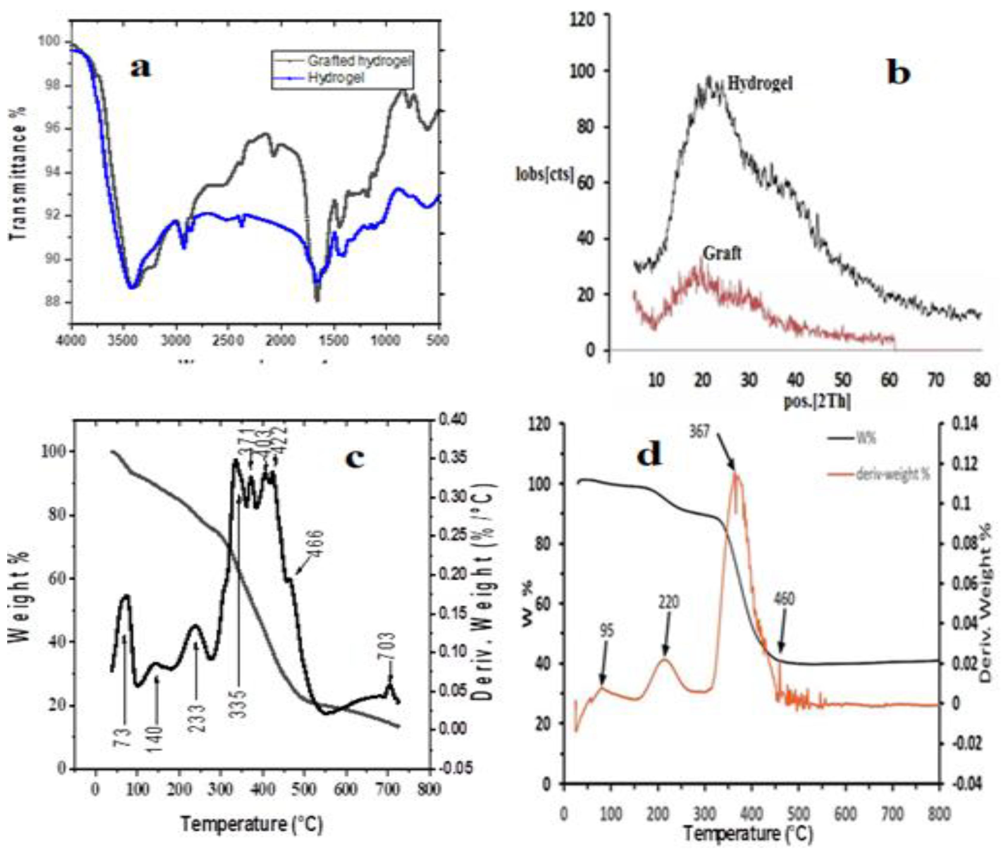
Figure 2.
SEM and TEM for PAC-PAM hydrogel (A) and grafted PAC-PAM hydrogel (B).
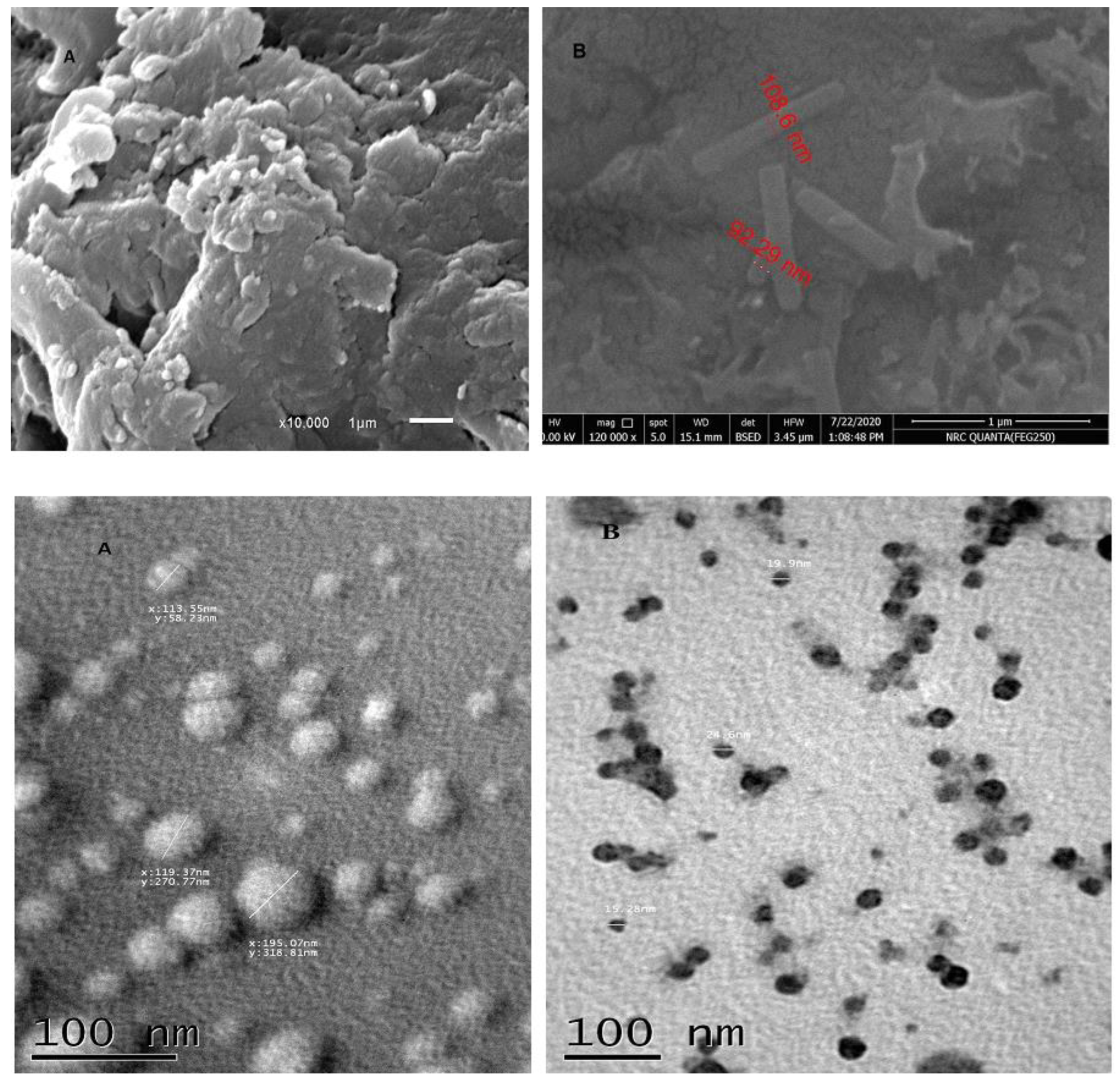
Figure 3.
The optimized structure, of the hydrogel showing the dipole moment vector (a), The numbers on atoms are the calculated charge density using NBO analysis (b) and The optimized structure, of the grafted hydrogel (c) at B3LYP/6-311G(d,p) level of theory.
Figure 3.
The optimized structure, of the hydrogel showing the dipole moment vector (a), The numbers on atoms are the calculated charge density using NBO analysis (b) and The optimized structure, of the grafted hydrogel (c) at B3LYP/6-311G(d,p) level of theory.
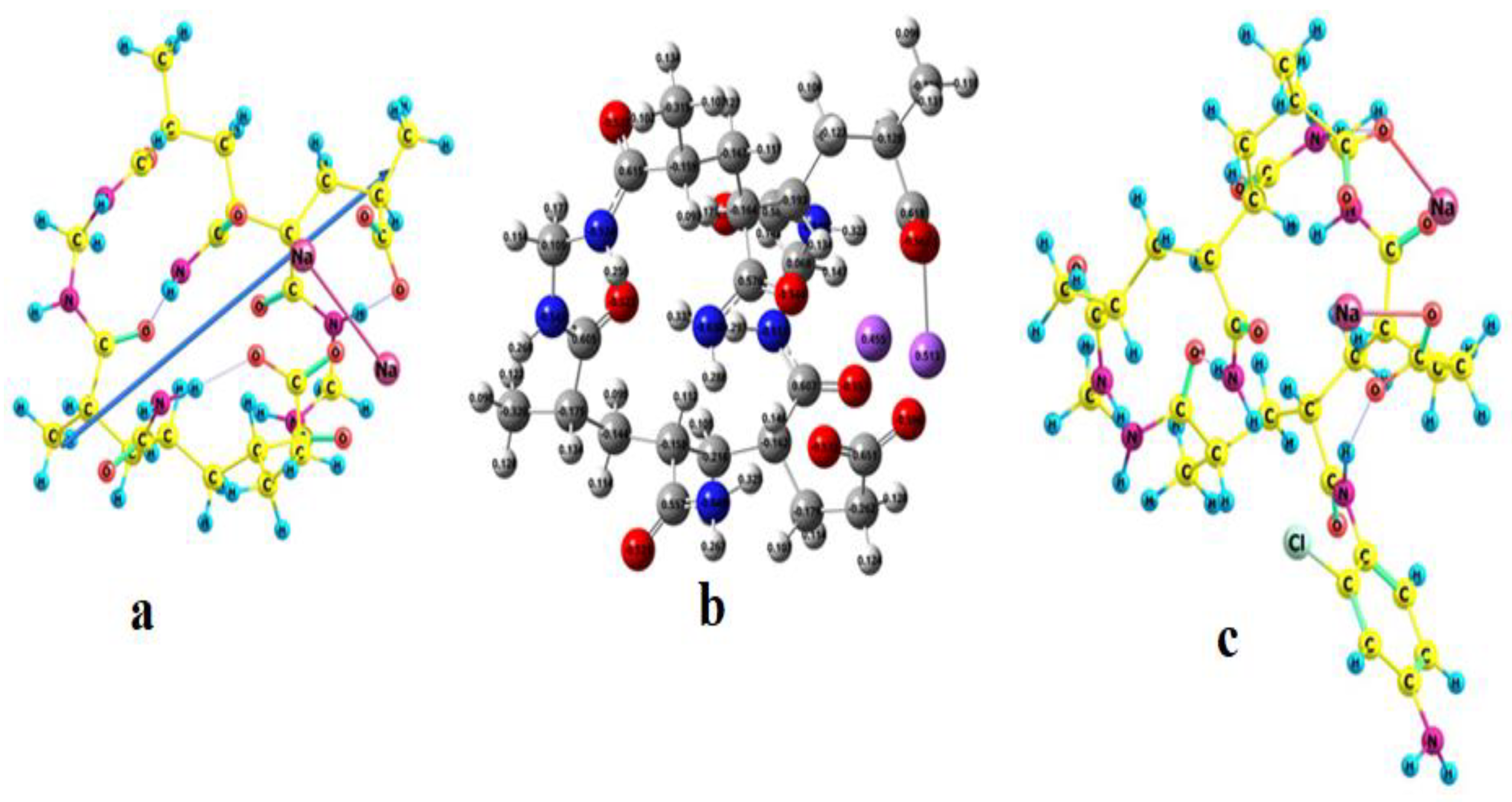
Figure 4.
Effect of grafted hydrogel doses on iron (a) and ammonia(b) removal, effect of contact time on the removal of ammonia (c) and iron(b).
Figure 4.
Effect of grafted hydrogel doses on iron (a) and ammonia(b) removal, effect of contact time on the removal of ammonia (c) and iron(b).
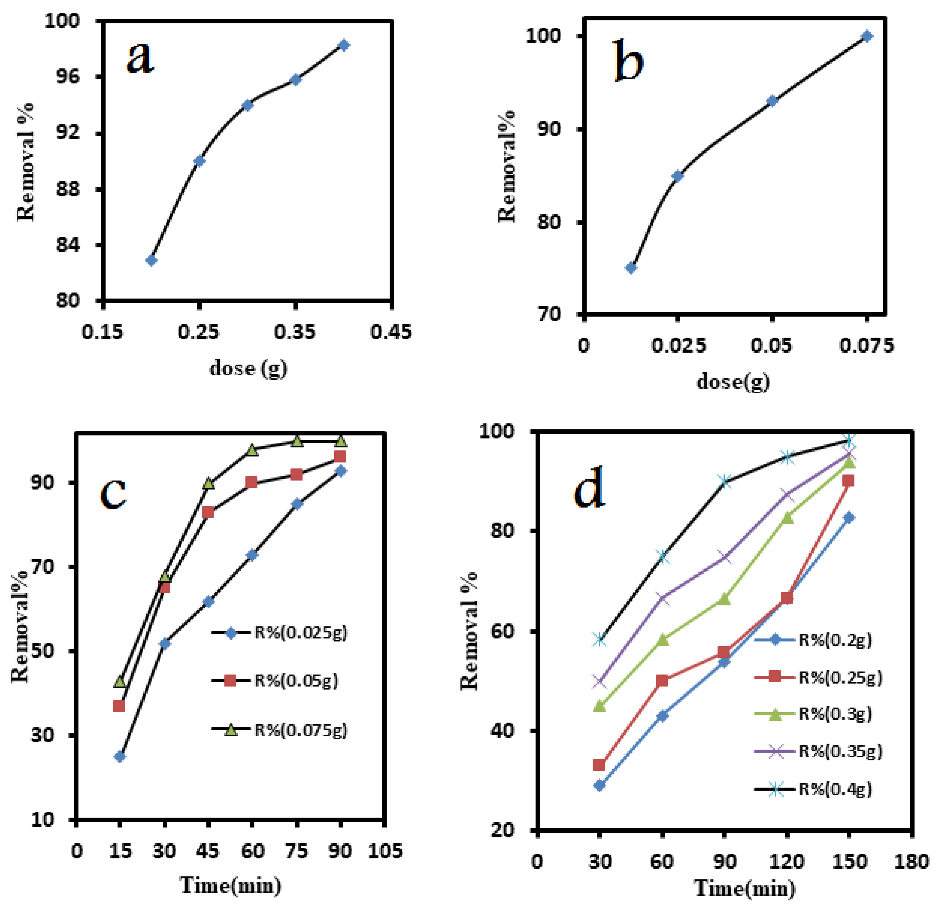
Figure 5.
Langmuir isotherm for iron (a) and ammonia (b) removal by grafted hydrogel. Freundlich isotherm for iron (c) and ammonia (d) removal by grafted hydrogel.
Figure 5.
Langmuir isotherm for iron (a) and ammonia (b) removal by grafted hydrogel. Freundlich isotherm for iron (c) and ammonia (d) removal by grafted hydrogel.
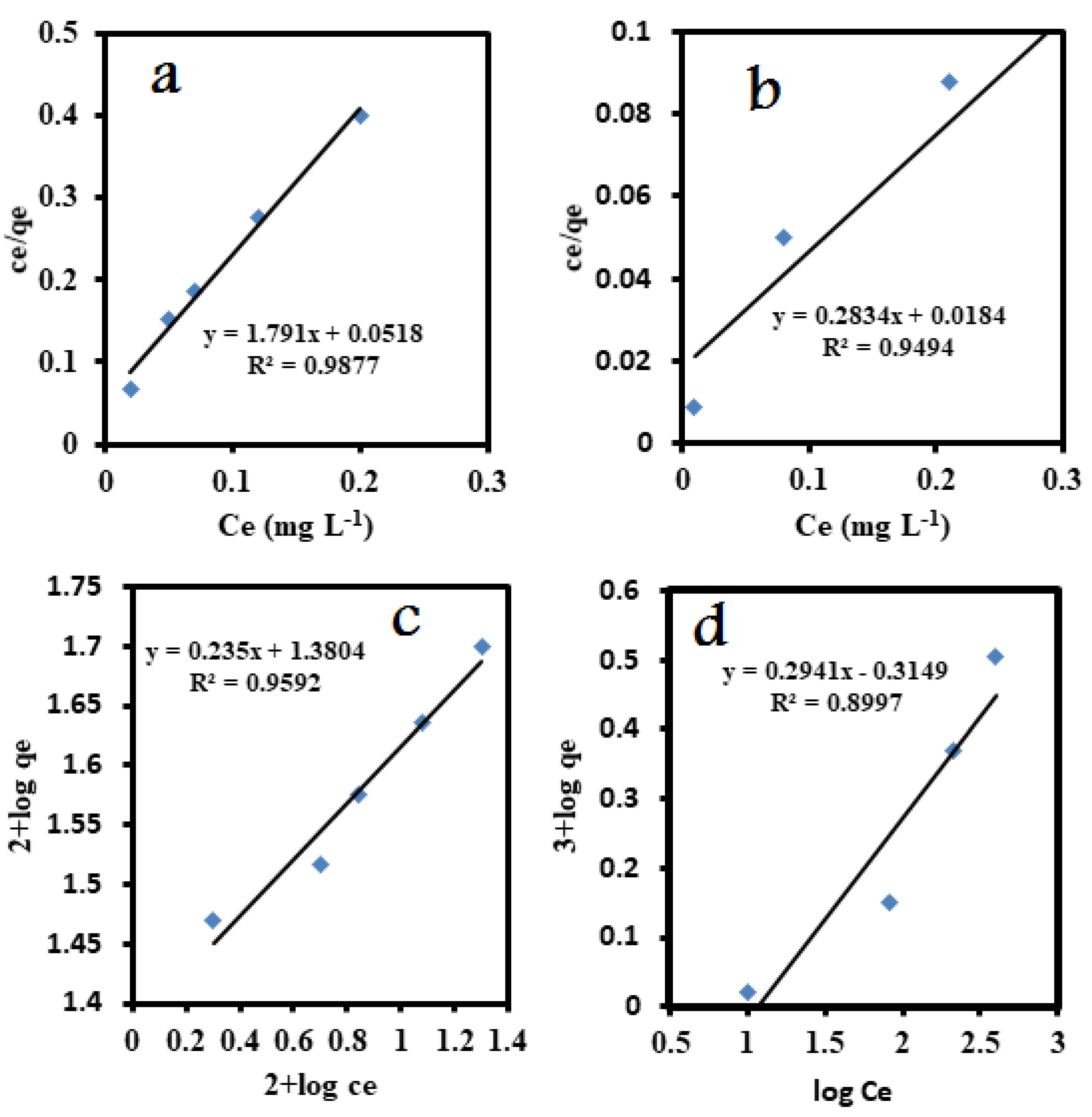
Figure 6.
Molecular electrostatic potential (MESP (-0.055 to 0.055)) of grafted hydrogel at B3LYP/6-311G(d,p) level of theory, Red for negative, blue for positive and green is in between.
Figure 6.
Molecular electrostatic potential (MESP (-0.055 to 0.055)) of grafted hydrogel at B3LYP/6-311G(d,p) level of theory, Red for negative, blue for positive and green is in between.
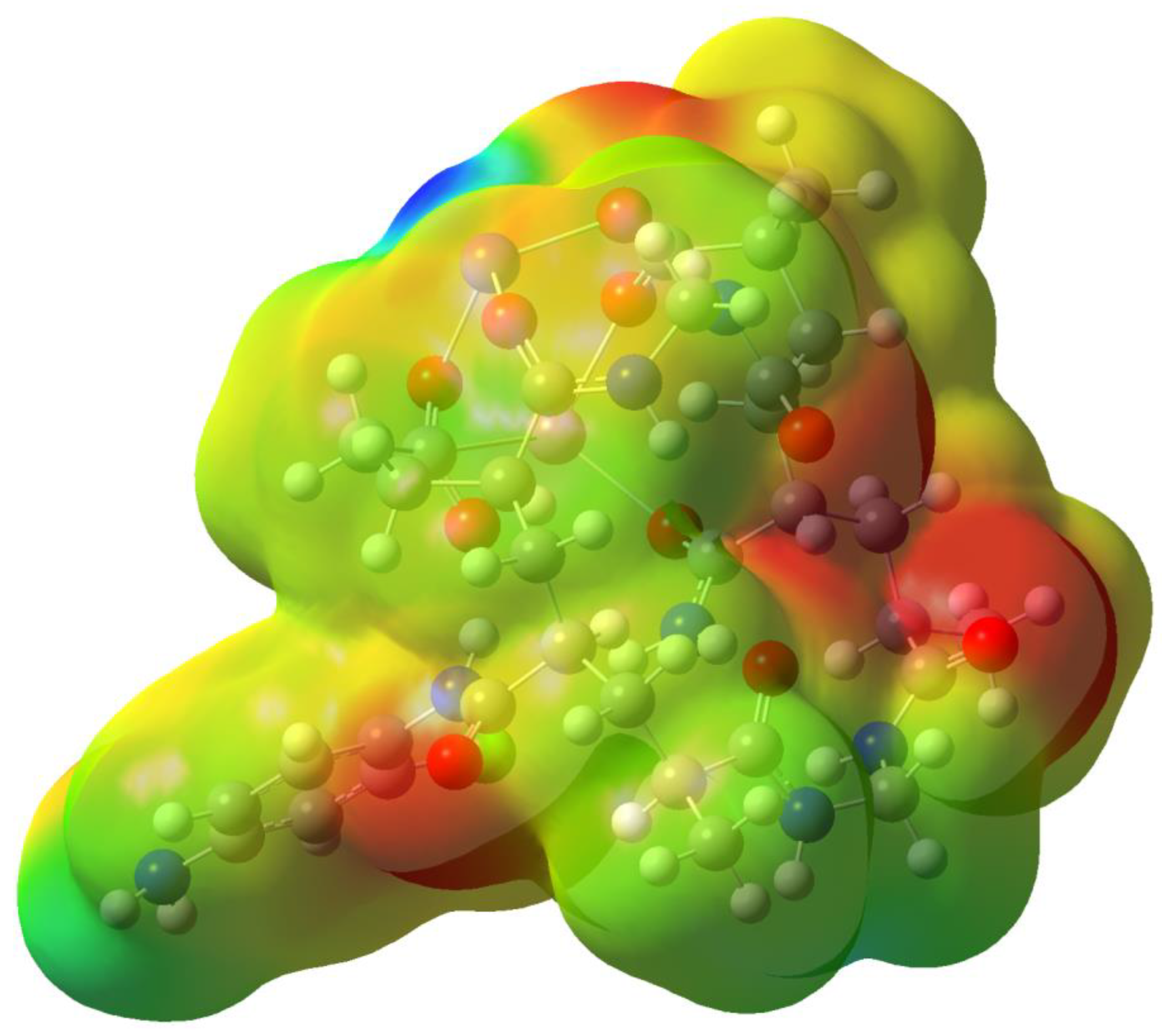
Figure 7.
The optimized structures of hydrogel-metal complexes (left NH4+, Middle Fe2+, right Fe3+) at B3LYP/6-311G(d,p) level theory.
Figure 7.
The optimized structures of hydrogel-metal complexes (left NH4+, Middle Fe2+, right Fe3+) at B3LYP/6-311G(d,p) level theory.
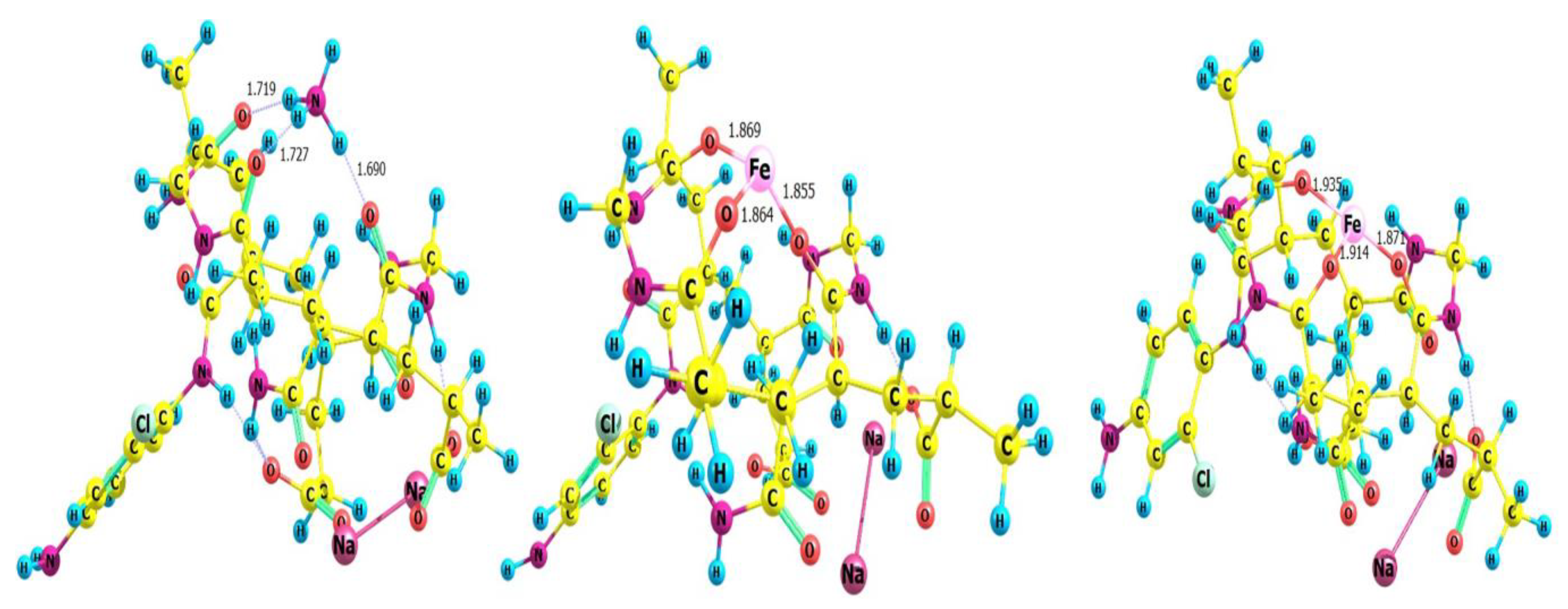

Table 1.
Ground water properties.
| Parameter | Before treatment | After treatment |
|---|---|---|
| Turbidity | 1.3 NTU | 1.2 NTU |
| Chlorides | 140 mg/L | 130 mg/L |
| Alkalinity | 320 mg/L | 320 mg/L |
| TDS (Total dissolved salts) |
710 mg/L | 650 mg/L |
| Total hardness | 280 mg/L | 250 mg/L |
| Ca hardness | 130 mg/L | 120 mg/L |
| Mg hardness | 150 mg/L | 130 mg/L |
| Ammonia | 0.8 mg/L | 0.0 mg/L |
| Iron | 1.2 mg/L | 0.02 mg/L |
Table 2.
Parameters for the adsorption of Ammonia and Iron using different isotherms.
| Model | Parameter | Parameter value | |
|---|---|---|---|
| Ammonia | Iron | ||
| Langmuir | Qm(mg g-1) | 3.52 | 0.55 |
| b | 15.439 | 35.1 | |
| R2 | 0.9494 | 0.9877 | |
| Freundlich | n | 3.4 | 4.25 |
| Kf | 2.06 | 24 | |
| R2 | 0.8997 | 0.9592 | |
| Temkin | BT(J/mol) | 0.5739 | 0.0904 |
| KT(L/g) | 2.76 | 85.39 | |
| R2 | 0.8502 | 0.9354 | |
Table 3.
The binding energies (ΔEbind and ΔEbind with (BSSE) correction, in kcal.mol–1),.
| Ion | Complexation Energy kcal/mol | |
|---|---|---|
| Method | (raw) | (corrected) BSSE |
| Iron(II) | -410.49 | -401.65 |
| Iron(III) | -990.86 | -920.7 |
| Ammonioum | -74.6 | -71.1 |
Disclaimer/Publisher’s Note: The statements, opinions and data contained in all publications are solely those of the individual author(s) and contributor(s) and not of MDPI and/or the editor(s). MDPI and/or the editor(s) disclaim responsibility for any injury to people or property resulting from any ideas, methods, instructions or products referred to in the content. |
© 2023 by the authors. Licensee MDPI, Basel, Switzerland. This article is an open access article distributed under the terms and conditions of the Creative Commons Attribution (CC BY) license (http://creativecommons.org/licenses/by/4.0/).
Copyright: This open access article is published under a Creative Commons CC BY 4.0 license, which permit the free download, distribution, and reuse, provided that the author and preprint are cited in any reuse.


