1. Introduction
Distributed power generation is actively researched as a respond to instability of power supply such as a large-scale blackout due to disaster. Distributed power generation directly produces and supplies power at demand, and stationary fuel cell are a representative of distributed power generation [
1,
2]. Stationary fuel cell for building have advantage of using a relatively small installation space for producing the same amount of energy compare to other renewable energies and using existing city gas infrastructure [
3,
4]. Therefore, demand for stationary fuel cell system for building is increasing worldwide. Also, electricity output, durability, system size, operation, installation, and operation costs of fuel cell systems are becoming competitive [
5,
6]. In particular, the fuel processor and fuel cell combined system efficiency is mainly affected by the fuel processor efficiency [
7,
8]. The flow rate of methane used for reactants and for burner fuel affects the reaction temperature in the steam reformer resulting in the change in conversion and also affect the overall efficiency of the combined system [
9]. In general, hydrogen production rate increases as the temperature of the reactor increases, but the overall thermal efficiency may decrease due to excessive input of burner fuel [
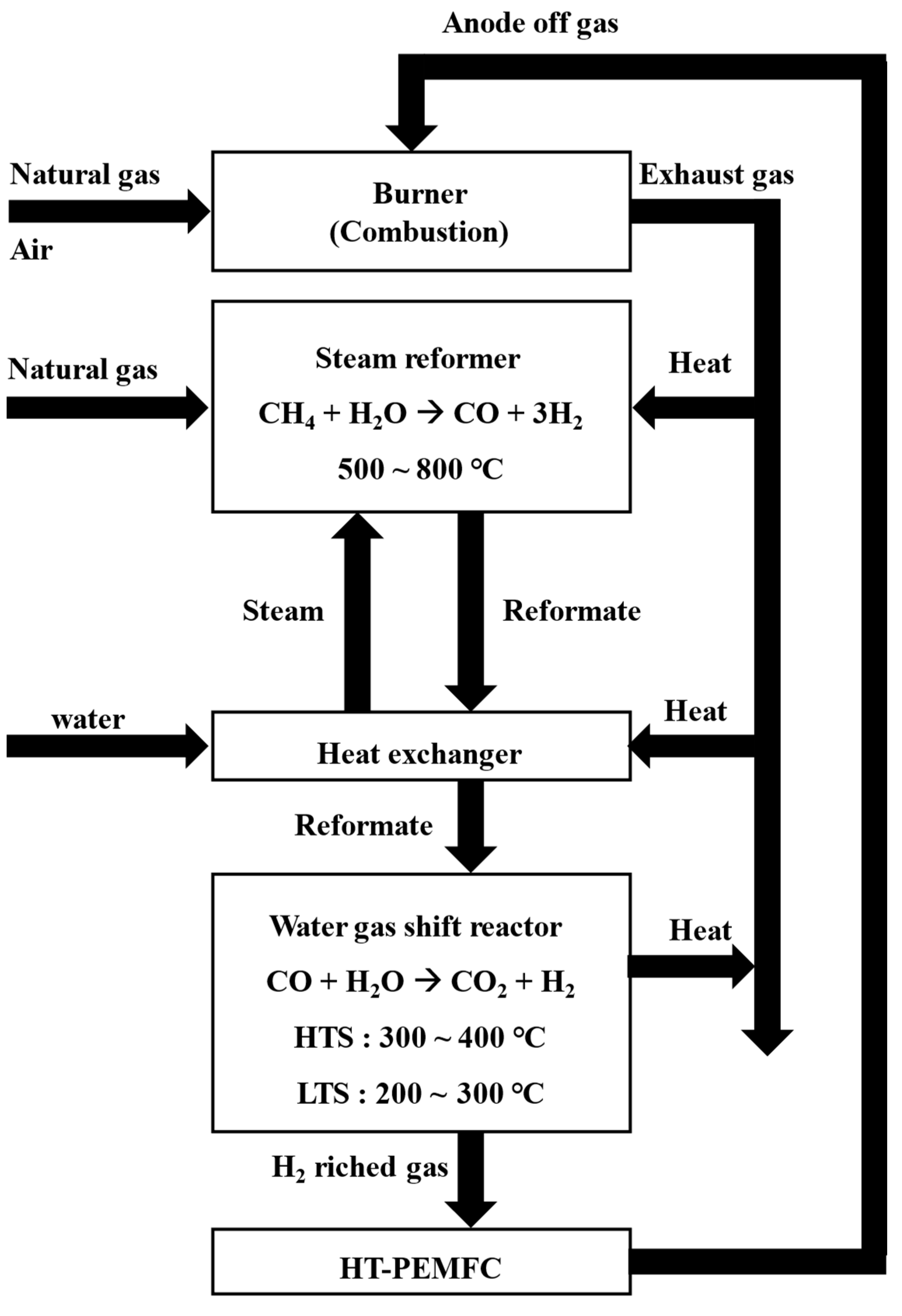
10]. Therefore, the fuel processor needs to be operated at optimal temperature conditions and used to operate within the temperature range shown in
Figure 1.
The fuel processor is composed of a steam reformer, a water-gas shift reactor, a burner, and heat exchangers [
11]. In a steam reformer, natural gas and steam reacts on nickel catalysts at 500 ℃ to 800 ℃ to produce hydrogen and carbon monoxide [
12]. Since the reforming reaction is an endothermic reaction, the reactor must be designed to supply sufficient amount of heat to keep the reaction temperature constant [
13,
14]. For this reason, a burner is installed close to where the steam reforming reaction takes place to provide sufficient thermal energy.
The heat from the exhaust gas, the reformed gas and the heat released from the steam reformer are recovered to heat the reactants, in particular water [
15]. Increasing the efficiency of fuel processors requires thermal energy optimization for heat transfer between exhaust gas, reformate and reactants.
The WGS (Water Gas Shift reactor) is classified into HTS (High Temperature Shift reactor) and LTS (Low Temperature Shift reactor) depending on the operating temperature (shown in
Figure 1). The WGS reactor shifts CO to CO
2 to prevent the CO poisoning of the fuel cell. A water-gas shift reaction is an exothermic reaction that needs to remove the reaction heat [
16]. LT-PEMFC (Low Temperature-Proton Exchange Membrane Fuel Cell) requires CO concentration to be less than 100 ppm [
17], whereas HT-PEMFC has sufficient durability even when CO is less than 1% [
18]. HT-PEMFC does not use a humidifier unit and is advantageous in high thermal efficiency using the thermal energy from high cell temperatures [
18,
19].
One of the ways to increase the total efficiency of the fuel processor and fuel cell combined system is to recirculate unreacted hydrogen discharged from the anode of the fuel cell to the burner as a fuel [
20,
21,
22,
23,
24,
25].
In this study, conditions such as operating temperature, S/C ratio, reactant flow rate, and burner fuel flow rate of each reactor were investigated to efficiently operate the combined system of fuel processing system and PEMFC stack. A theoretical model based on thermodynamic analysis was applied and the overall efficiency of the combined process was investigated at various operating temperatures using the Aspen Hysys® simulator.
2. Modelling
Simulations were performed for a combined system of fuel processor and HT-PEMFC with a recycle stream of anode off gas to a burner installed in the SR (Steam Reformer). The fuel processing system consists of a steam reformer, two water gas shift reactors (high temperature shift reactor and low temperature shift reactor), and heat exchangers.
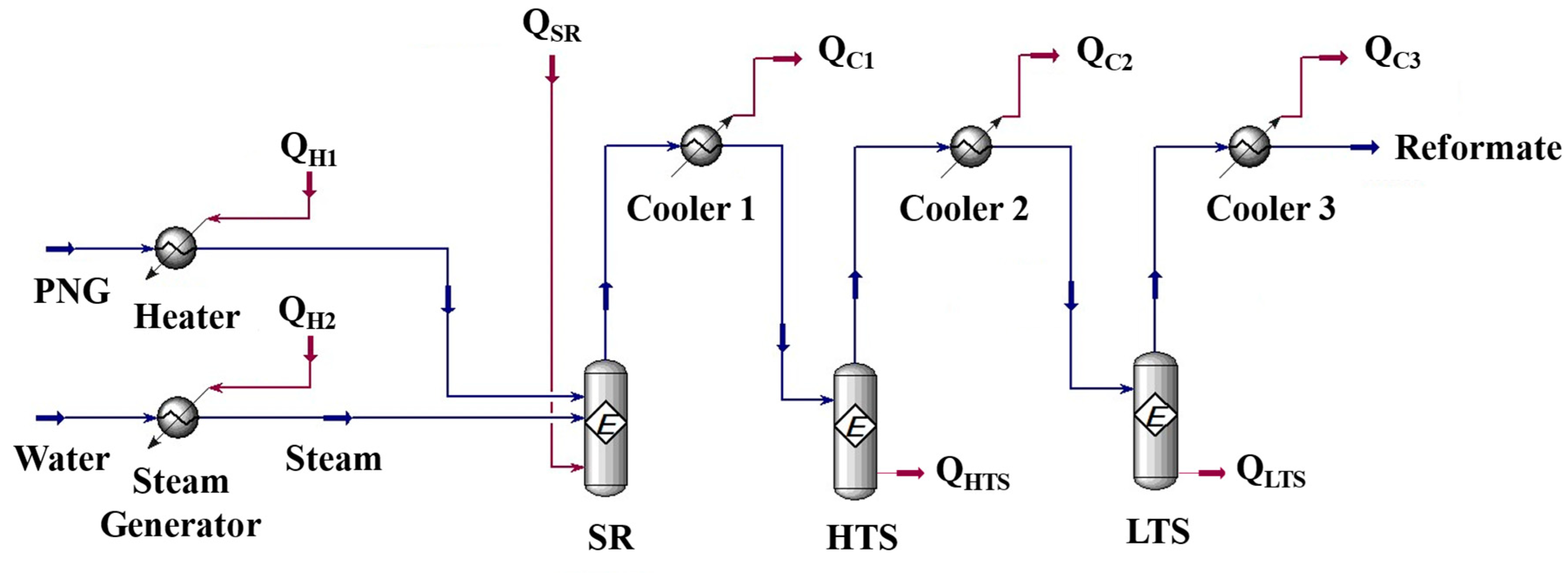
Figure 2 shows the process flow diagram by Aspen Hysys®. PNG (Process Natural Gas) is introduced to the reformer and reacted with steam to form hydrogen. Q
H1 is the heat required to raise the PNG to the reaction temperature of the steam reformer. Q
H2 is the heat required to turn water into the steam up to the reaction temperature of the reformer. The product gas from the steam reformer is cooled down by a heat exchanger (cooler 1 in
Figure 2) to the high temperature water-gas shift reactor (HTS) operating temperature and then introduced to the HTS. CO converted into CO
2 with steam at the HTS and the concentration of CO in the HTS product gas would be lowered less than 3%. To reduce the CO concentration lower than 1%, HTS product gas cooled again and introduced to the low temperature water-gas shift reactor [
26]. The heat released in the process was named Q
c1, Q
c2, Q
c3. Q
SR is the energy required for the reaction at steam reformer. Q
HTS is the heat of reaction at high temperature water-gas shift reactor and Q
LTS is the heat of reaction at low temperature water-gas shift reactor.
In the steam reformer, two main reactions are considered [
27,
28,
29] : the steam reforming reaction (equation (1)) and the WGS reaction (equation (2)). It is assumed that the reaction proceeds to equilibrium conditions in each reactor, and the equilibrium reactor is used for the simulation with the equilibrium constants (
KSR and
KWGS) calculated the equations (3) and (4).
Equation (3) and (4) are empirical equations presented by Twigg [
30], and the equilibrium constants (
KSR and
KWGS) are expressed as a function of temperature (Z and T) instead of each partial pressure. The WGS reactor applied
KWGS within the temperature range of reactor. Equilibrium constants calculated for each reaction are summarized in
Table 1.
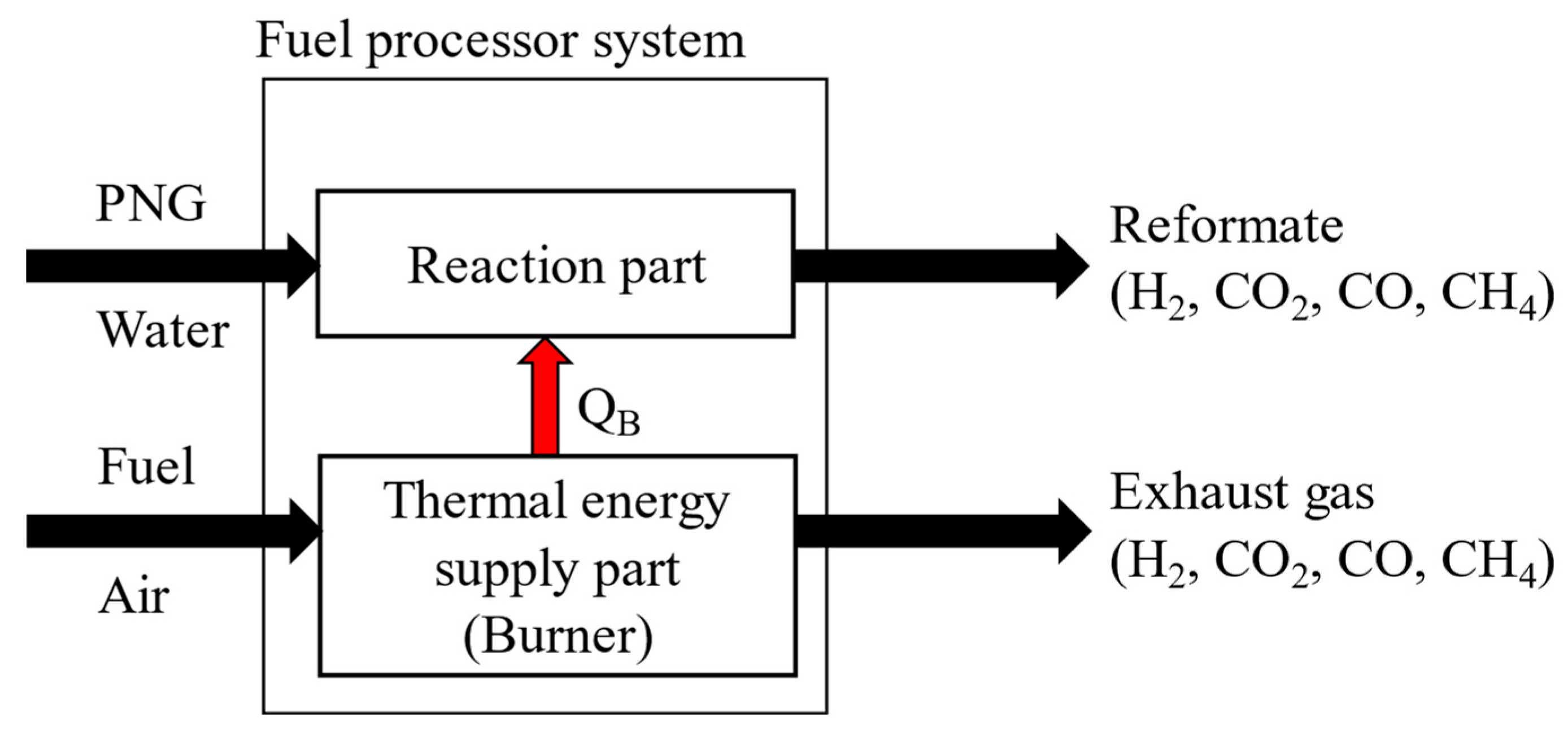
To calculate the thermal energy and heat of reaction in each component, energy balances are applied. As shown in
Figure 3, the fuel processor consists of two independent parts. One is the reaction part and the other is the thermal energy supply part. The thermal energy required is calculated as the enthalpy difference between the inlet stream and the outlet stream. (equations (6), and (7)), which can be supplied by the methane burner via combustion. Since the entire system must operate at a steady state, the total reactive energy required (Q
RE) is equal to the amount of energy supplied by the burner through combustion (Q
CE).
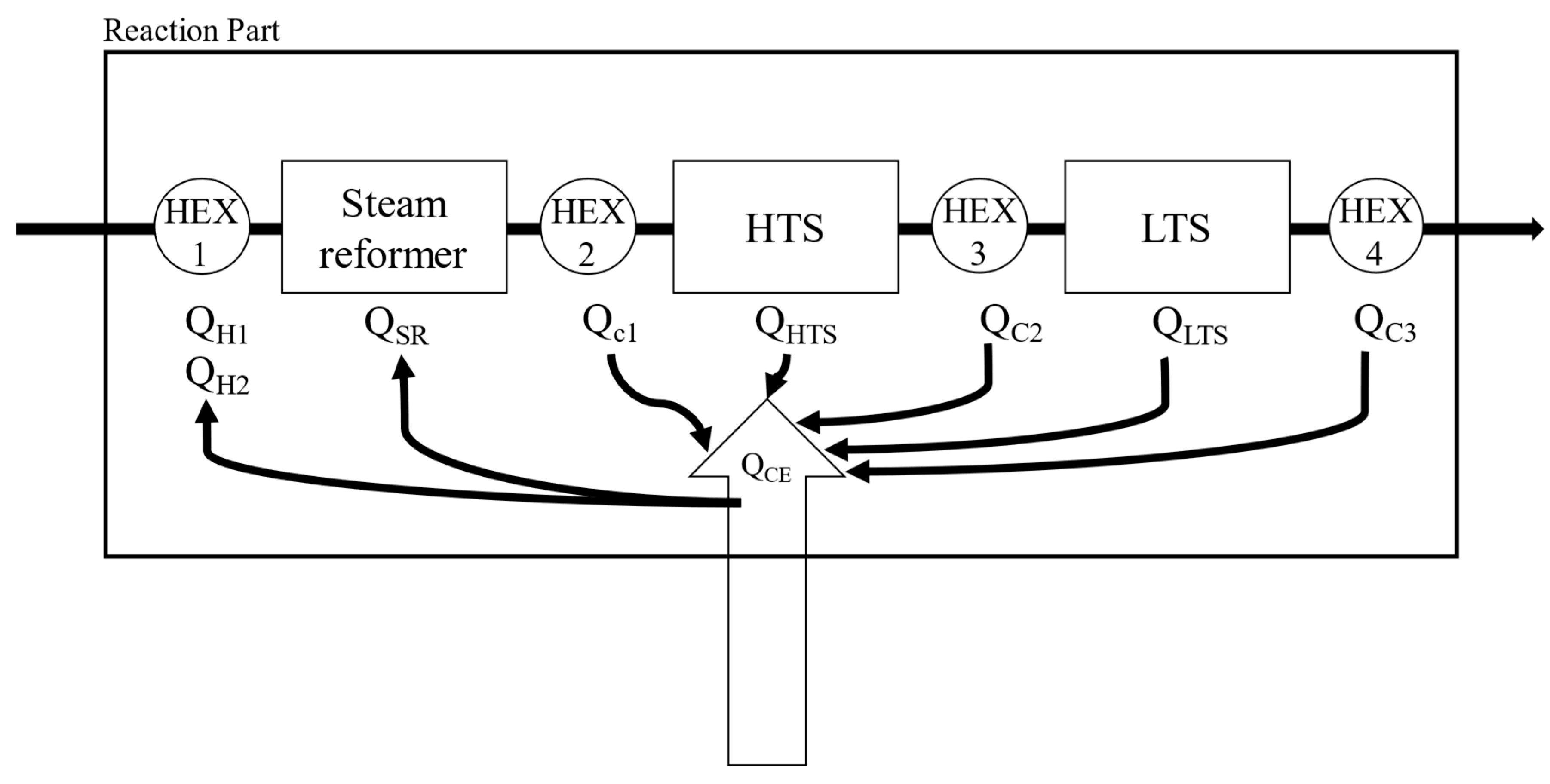
The required energy of reaction section can be calculated by summing the heat of reaction, the heat energy for heating the reactants, or for cooling the products as shown in equation (8). In equation (8) each energy is calculated by the enthalpy difference between the inlet stream and outlet stream. The enthalpy of each stream would be a function of the temperature, flowrate and the degree of reaction.
Figure 4 shows the above explanation intuitively.
The thermal efficiency of the fuel processor system (η
FP) was defined as equation (9) [
31,
32,
33].
The thermal efficiency of the fuel processor is calculated by dividing the energy of produced hydrogen by the total energy supplied to the process (PNG, natural gas to burner, AOG).
The product gas containing produced hydrogen is cooled in the cooler Q
C3 system to remove moisture in the product gas and supplied to the PEMFC. Hydrogen is supplied to the anode side and oxygen from the air is supplied to the cathode side of the PEMFC. Using the electrochemical reaction, electrical energy is produced. To calculate the amount of electrical energy produced by the PEMFC, fuel utilization efficiency, irreversibility of the PEMFC should be considered. Detailed simulation condition for the fuel processing system is summarized in
Table 2.
S/C ratio is defined as in equation (10), and is a value obtained by dividing the moles of steam introduced by the moles of carbon.
PEMFC description
Since the flow rate of unreacted hydrogen in AOG is inversely proportional to the fuel utilization efficiency of the PEMFC, proper prediction of fuel utilization efficiency would be important to calculate the hydrogen consumption rate in the PEMFC. Power by the PEMFC stack (
Pstack) can be calculated as the product of the number of unit cell (
ncell), unit cell voltage (
Vcell), unit cell current (
i), and MEA area (
AMEA) as shown in equation (11).
The unit cell voltage in equation (11) can be calculated from equation (12) considering the thermodynamic equilibrium potential (
Vo), and the irreversibility of the PEMFC such as the activation loss (η
act), ohmic loss (η
ohm), and concentration loss (η
con) [
34].
The thermodynamic equilibrium potential, activation loss, ohmic loss, and concentration loss are calculated by equations (13) to (17). The equation (13) can calculate the thermodynamic equilibrium potential in HT-PEMFC. Equation (13) is a function of cell temperature (
Tcell) and 1.1549 V was calculated using a cell temperature of 150 ℃ [
35,
36] .
Activation loss can be calculated by Butler-Volmer equation that express the electrochemical kinetics [
34]. Since hydrogen oxidation reaction and oxygen reduction reaction occur in anode and cathode in fuel cell, Butler-Volmer equations are using the two half reactions of equation (14) and equation (15) to calculate the activation loss [
34,
35,
36,
37,
38].
Resistance loss and concentration loss occur according to the structural characteristics of the fuel cell (thickness, electronic conductivity, porosity, etc.) and represent losses by hindering the movement of hydrogen protons and electrons. To express η
ohm and η
con, Jo and his colleague suggest the Equations (16) and (17) [
35].
The parameters in the equations (14) ~ (17) are shown in
Table 3.
The current density of a stack (
i) is a function of the H
2 molar flow rate (
nH2) entering the stack, the fuel utilization efficiency (
Uf), the MEA area (
AMEA) and number of cells (
ncell) as shown in equation (18).
Fuel utilization efficiency is shown by equation (19) and defined by the ratio of the fuel used by the HT-PEMFC to generate power to the total fuel supplied to the HT-PEMFC [
34].
Total energy efficiency of the whole system would be defined as the ratio between the produced energy to the supplied energy and can be calculated by equation (20) [
39,
40]
In equation (20), Pstack is the power (Joule/sec), nBNG is the moles of natural gas supplied to the burner (mole/sec), nPNG is the moles of natural gas supplied to the reformer (mole/sec), LHVNG is the lower heating value of the natural gas (Joule/mole).
Sensitivity analysis
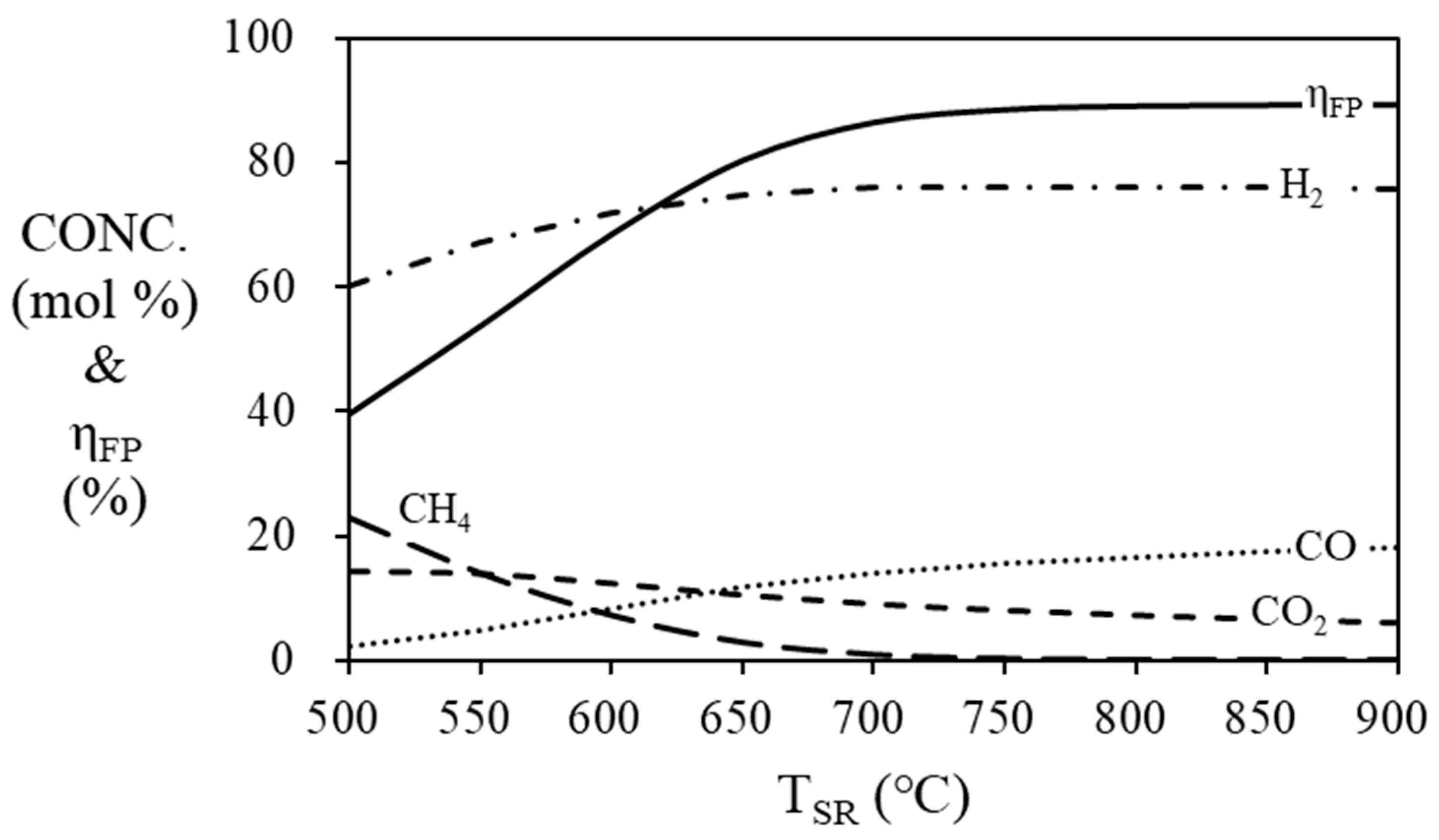
The simulation results (
Figure 5) show the mole fraction of the gas produced in the steam reformer at 500 ~ 900 ℃. As the temperature of the steam reformer increases, the mole concentration of hydrogen increases and the thermal efficiency of fuel processor increases, and they are stabilized at 700 ℃ or higher. The highest thermal efficiency of the fuel processor is confirmed to be 89.15% at 900 ℃, 88.38% at 800 ℃ and 86.36% at 700 ℃. In order to prevent degradation of the catalysts, the operating temperature should be lower than 800 ℃ [
41].
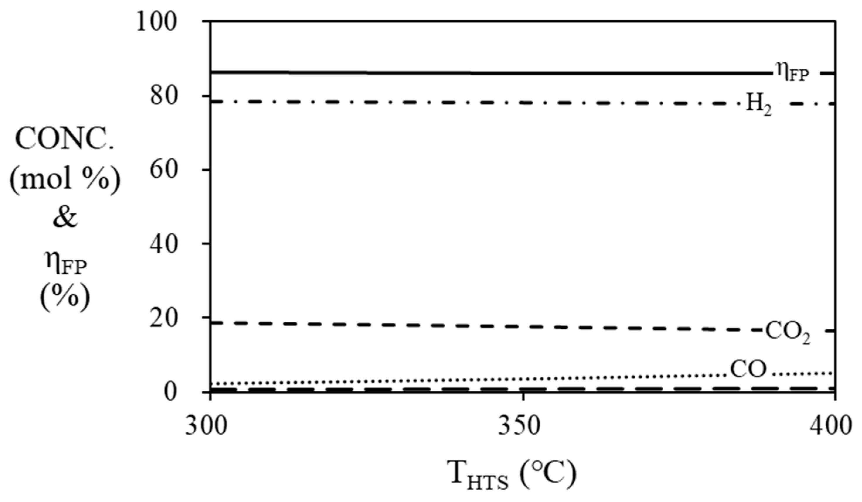
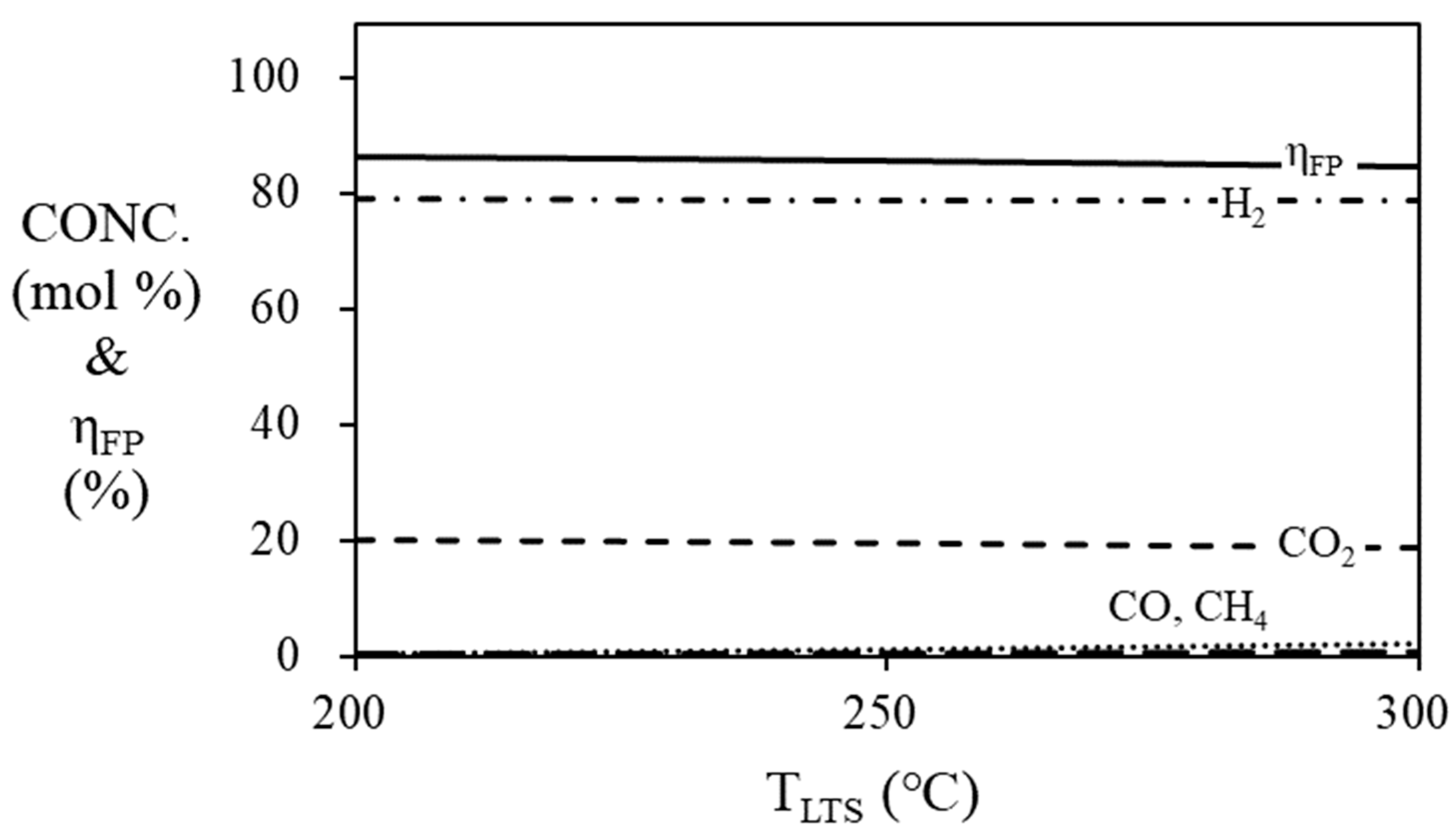
Figure 6 and
Figure 7 are simulation results of mole fraction and thermal efficiency of fuel processor according to HTS and LTS temperatures. For HTS, the thermal efficiency of the fuel processor was 86.36% regardless of temperature. For LTS, the thermal efficiency of the fuel processor was decreased by 2% when the temperature was increased from 200 ℃ (86.36%) to 300 ℃ (84.36%). Since the HTS and LTS generate a relatively smaller amount of hydrogen compared to the steam reformer, the contribution to the thermal efficiency of the fuel processor according to the temperature change of the HTS or LTS is not significant. Therefore, the operating temperature of the HTS was fixed at 400
oC [
26], and the operating temperature of the LTS was fixed at 200
oC in the simulation, so that the HTS and LTS each showed the highest efficiency.
As shown in
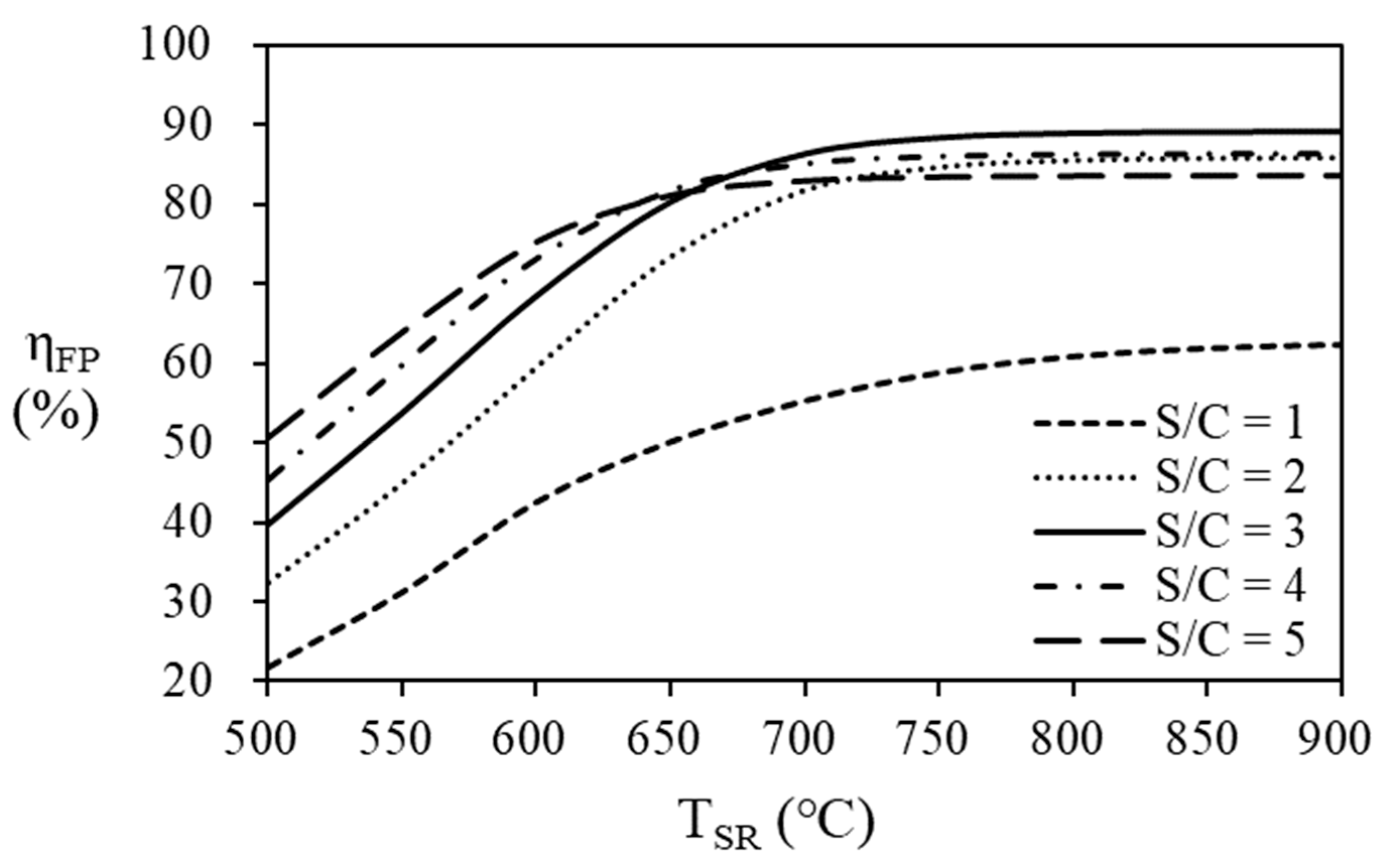
Figure 8 and
Table 3, the thermal efficiency of the fuel processor increases as the S/C ratio increases at the steam reformer temperature below 650 ℃. As the steam reformer temperature increases, the thermal efficiency of fuel processor increases. However, the thermal efficiency according to the S/C ratio seems to have a maximum point according to the S/C ratio at a temperature of 650
oC or higher in the steam reformer. At the steam reformer temperature of 650 ℃, the highest efficiency was 81.81% at an S/C ratio of 4, but at a temperature of 700 ℃ or higher, case the highest efficiency was obtained at an S/C ratio of 3. At the reformer temperature of 700
oC or lower, the highest thermal efficiency of 86.36% was obtained at an SCR of 3.
At higher temperatures, the conversion of natural gas to hydrogen increases and more natural gas enters the burner for providing heat to the reactants (natural gas and water) to produce maximum thermal efficiency at different S/C ratios with temperature.
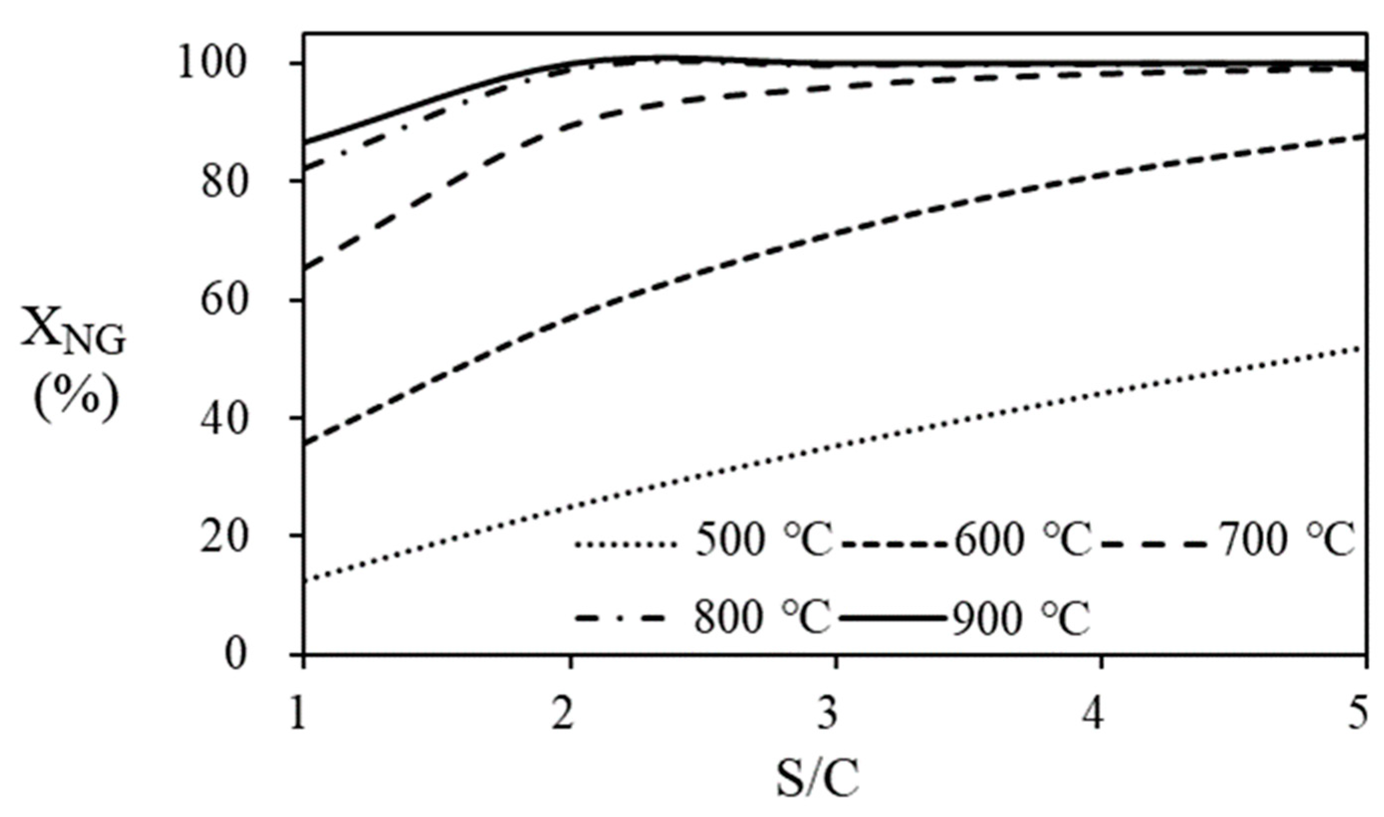
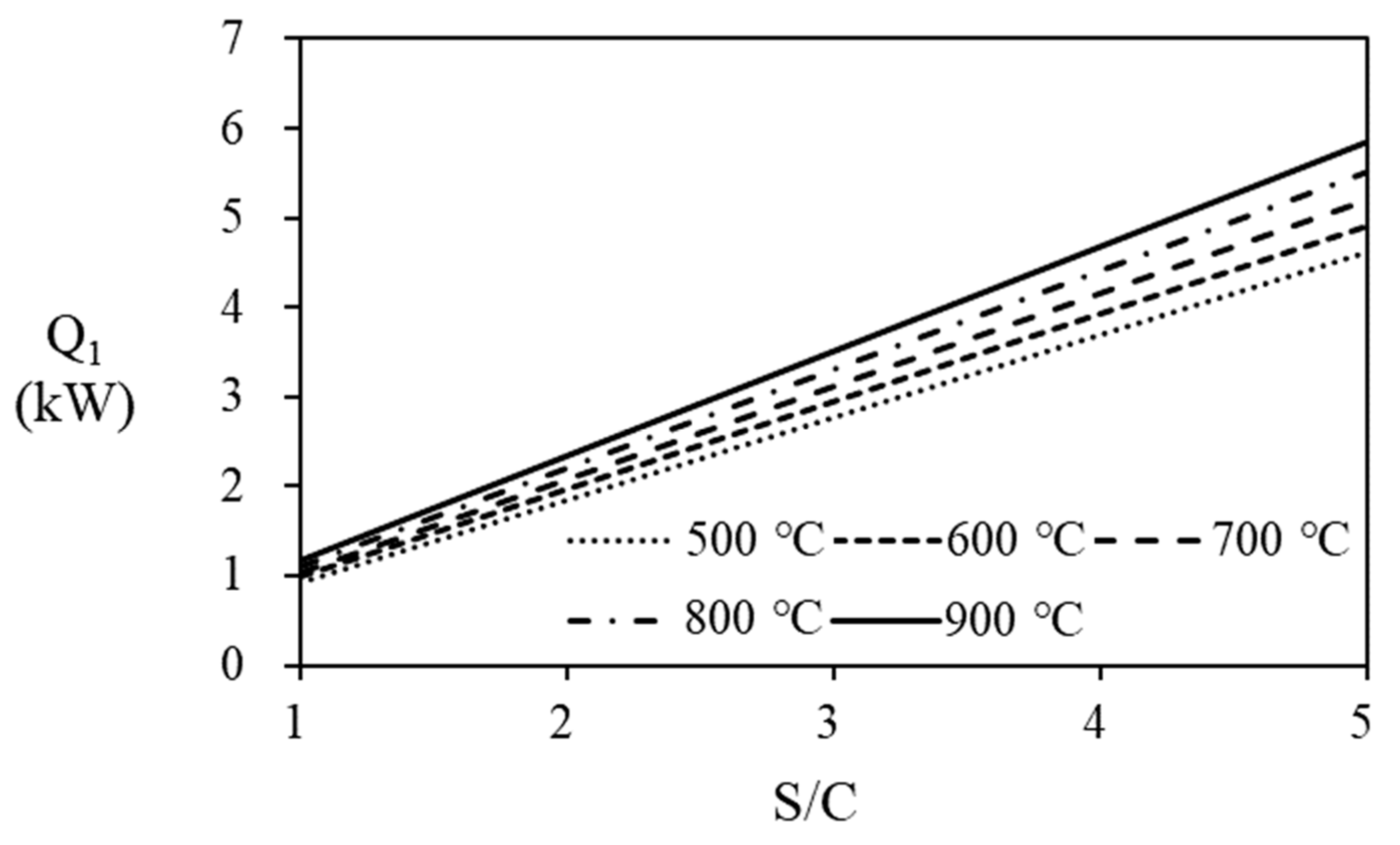
Figure 9 shows the conversion of natural gas according to S/C ratio and temperature of the steam reformer. The conversion of natural gas to hydrogen is calculated based on the molar flow rate of natural gas entering and leaving the steam reformer and indicates the degree of reaction. The amount of heat required to bring the water temperature to the operating temperature of the steam reformer at various S/C ratios and temperatures is shown in
Figure 10. Since larger amount of water is supplied to the system at high S/C ratio, the amount of heat required is increased according to the increase of S/C ratio. On the other hand, since the natural gas conversion is more than 95% at 700 ℃ of temperature and 3 of the S/C ratio, the increase in produced hydrogen flow rate with increasing in S/C ratio at the temperature of 700
oC and higher is inevitably small.
Anode off gas recycling
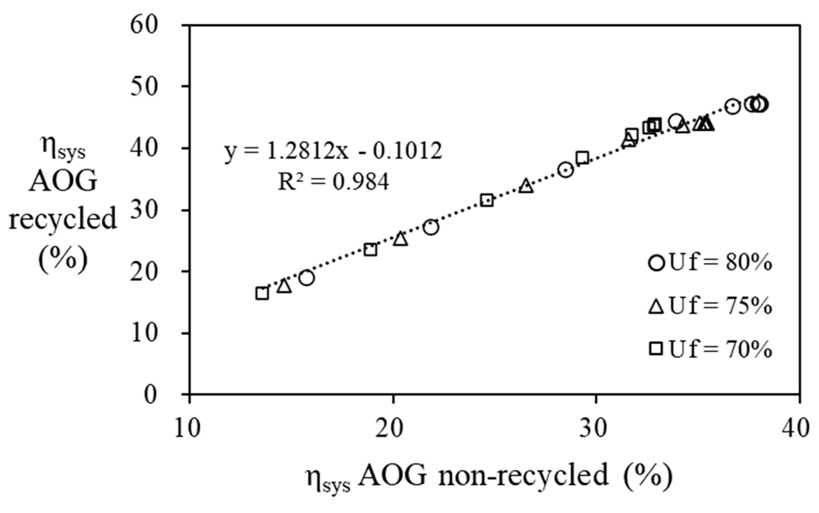
Unreacted hydrogen in the anode off gas from the PEMFC stack that can recycled as fuel to the steam reformer’s burner, increasing the thermal efficiency of fuel processer and PEMFC. The thermal efficiency for the combined system depends on the amount of hydrogen recycled that is determined according to the fuel utilization ratio of the PEMFC. Calculated stack power is summerized on
Table 4, which are depending on the natural gas supplied to the fuel processor and the fuel utiliztion efficiency of the stack. In
Table 4, conditions for making more than 5kW power are shaded. on, The power increases at higher fuel utilization at the stack, at higher steam reformer operating temperature, and the higher flow rate of PNG. To increase the thermal efficiency of the fuel proserroer and PEMFC stack, anode off gas is recycled to the burner. In the
Figure 11, it can be seen that recycling AOG increases the efficiency of the fuel cell system by 1.28 times compared to the case without it.
Table 4.
Thermal efficiency of fuel processor corresponding to steam reformer temperature and S/C ratio. (The bold and border represent the maximum efficiency at the same temperature).
Table 4.
Thermal efficiency of fuel processor corresponding to steam reformer temperature and S/C ratio. (The bold and border represent the maximum efficiency at the same temperature).
Table 5.
Power of fuel cell versus temperature, fuel utilization efficiency, and molar flow rate of process natural gas. (bold and border are an area that satisfies the target capacity of 5kW, simulation condition: S/C = 3).
Table 5.
Power of fuel cell versus temperature, fuel utilization efficiency, and molar flow rate of process natural gas. (bold and border are an area that satisfies the target capacity of 5kW, simulation condition: S/C = 3).
|
Uf (%) |
TSR (℃) |
70 % |
75 % |
80 % |
| nPNG (mol/min) |
|
0.7 |
0.8 |
0.9 |
0.7 |
0.8 |
0.9 |
0.7 |
0.8 |
0.9 |
| |
600 |
3.18 |
3.68 |
4.18 |
3.43 |
3.97 |
4.51 |
3.68 |
4.26 |
4.84 |
| |
650 |
3.87 |
4.48 |
5.09 |
4.18 |
4.83 |
5.48 |
4.48 |
5.18 |
5.88 |
| Pstack (kW) |
700 |
4.25 |
4.91 |
5.58 |
4.58 |
5.29 |
6.01 |
4.91 |
5.67 |
6.44 |
| |
750 |
4.37 |
5.05 |
5.74 |
4.71 |
5.45 |
6.19 |
5.05 |
5.84 |
6.63 |
| |
800 |
4.41 |
5.09 |
5.79 |
4.75 |
5.49 |
6.24 |
5.09 |
5.89 |
6.69 |
However, some of calculations are excluded by the details described below in
Figure 12.
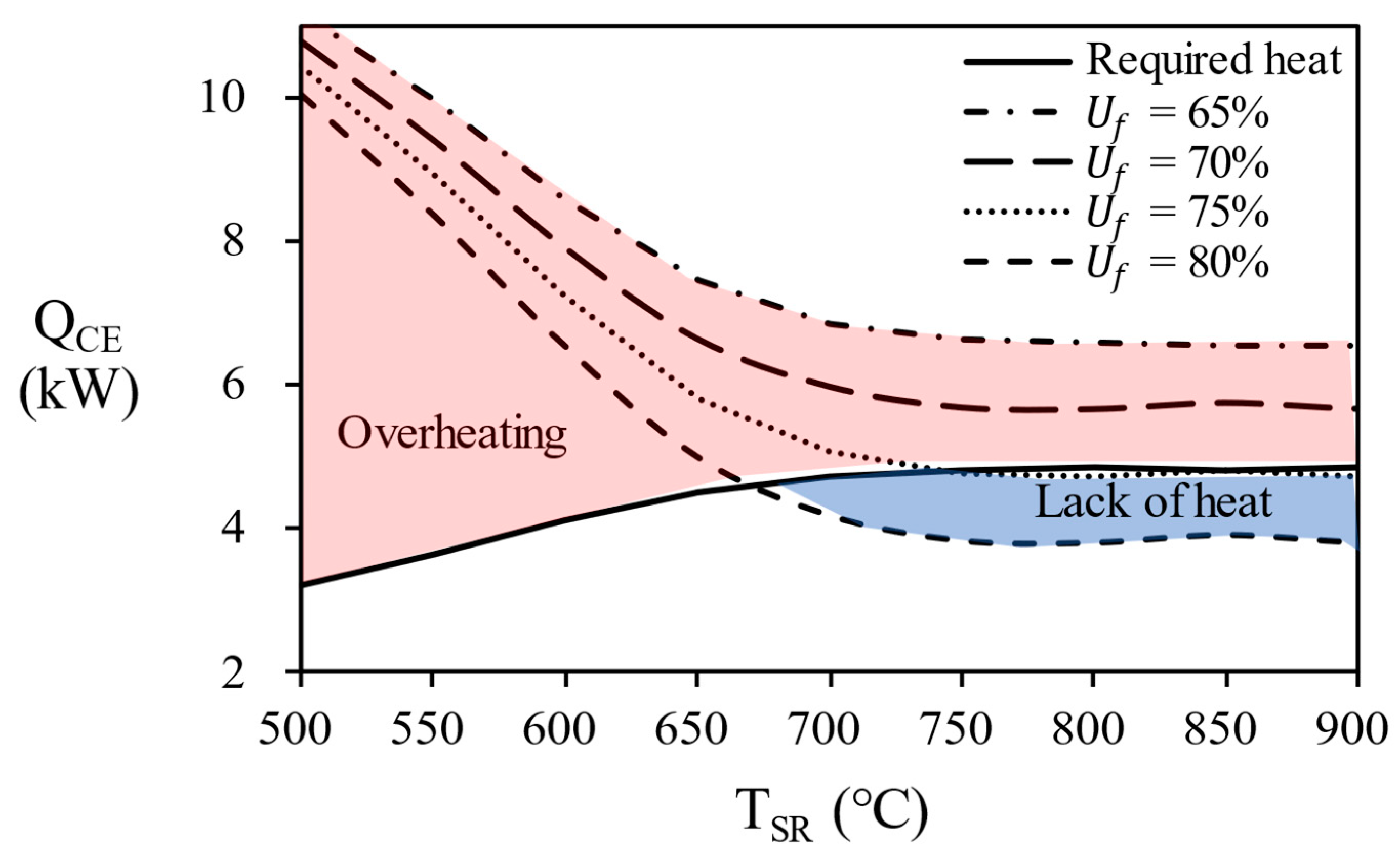
Figure 12 shows the combustion energy generated by each process at various temperature of the steam reformer. The flow rate of unreacted hydrogen in the anode off gas varies depending on the fuel utilization (
Uf) in the stack, which causes the combustion energy to vary. If the combustion energy of the anode off gas is greater (red area in
Figure 12) than the combustion energy of natural gas, excess energy is supplied to the reactor and reactor temperature will increases. Since the use of AOG in this section does not maintain the temperature, it is excluded from the result of the fuel utilization of 70% or less in this study. Conversely, if the combustion energy of the anode off gas is smaller (blue area in
Figure 12) than required heat, additional natural gas to burner must be introduced to maintain the temperature of the reactor.
In
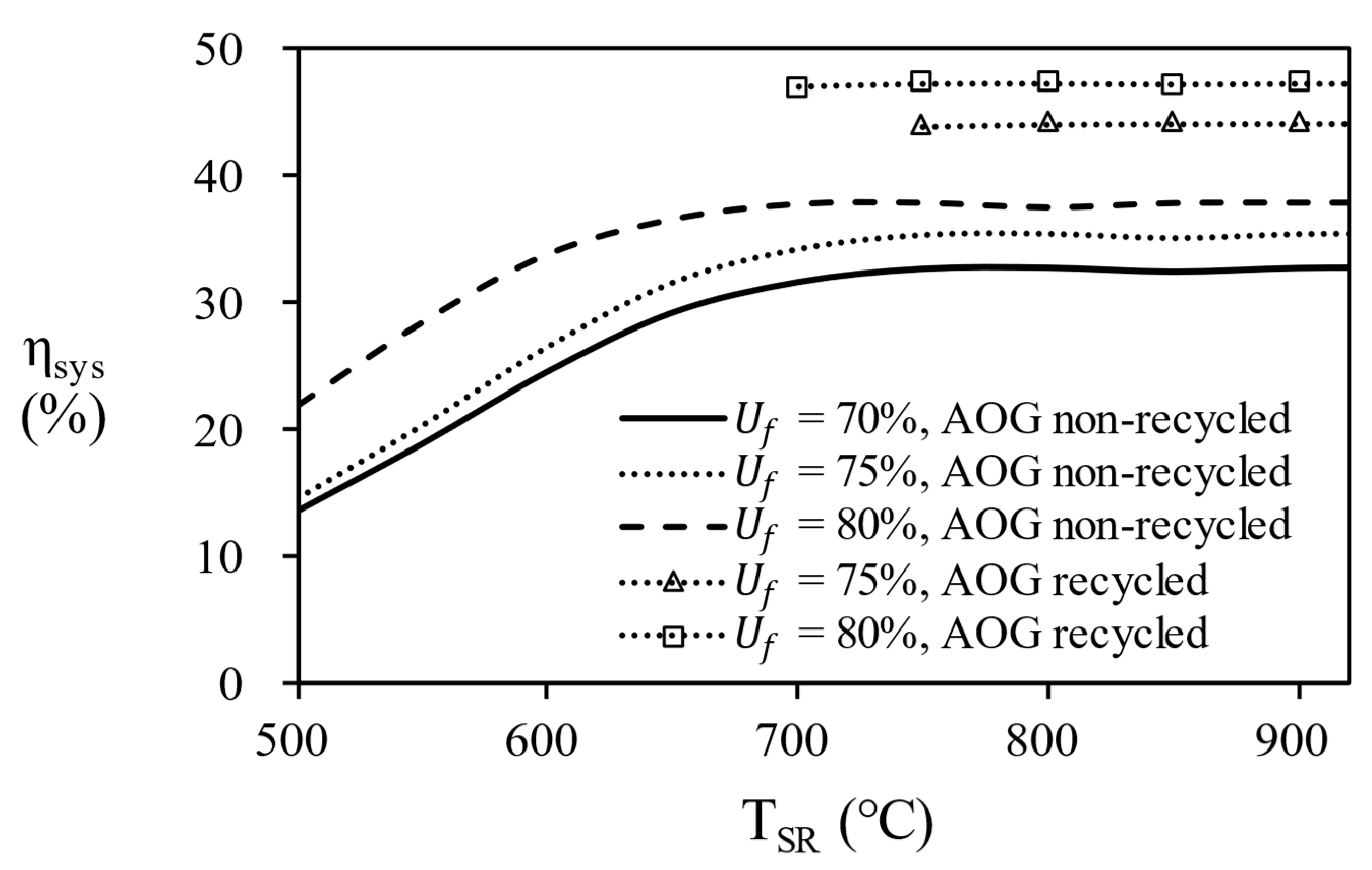
Figure 13, the overall efficiency of system according to the temperature of the steam reformer for each process. since 80% of AOG has a little small combustion energy, it is possible to reach maximum efficiency by supplying additional natural gas. Finally, in the case of AOG 75%, the value was consistent with the required heat, showing that the reformer can be operated only with AOG without additional fuel supply. In other words, energy independence is possible under the conditions of 750 ℃ or more, fuel utilization efficiency = 75%, and S/C = 3.
Table 6 shows the final selected operating conditions and system efficiency for 5 kW residential PEMFC. Consequently, the efficiency of fuel cell system is recommended under the conditions listed below : S/C = 3 with maximum efficiency of fuel processor, fuel utilization efficiency without overheating (75% ~ 80%), steam reformer temperature (700 ~ 800 ℃) and molar flow rate of PNG (0.8 ~ 0.9 mol/min) of producing more than 5 kW.
4. Conclusion
To increase the overall system efficiency of fuel processor and HT-PEMFC combined system, the thermal efficiency of fuel processor must be improved. This study suggests the two ways for increasing the efficiency:
1) Optimizing the operating condition (Temperature of reactor, S/C ratio, Reactant flow rate) having high thermal efficiency
2) Recycling of unreacted hydrogen in anode of HT-PEMFC.
The fuel processor consisting of an equilibrium reactors and heat exchangers was analyzed by Aspen Hysys® simulator and the operating conditions were optimized at the highest efficiency. In the simulation results, the effect of the temperature change of the WGS was less sensitive than that of the steam reformer, and at maximum efficiency, the operating temperature of the HTS was 400 °C and the operating temperature of the LTS was 200 °C. As the temperature and S/C ratio of the steam reformer increase, the hydrogen concentration of the reformate gas increases, but the thermal efficiency of the fuel processor decreases. The steam reformer showed maximum thermal efficiency at S/C ratio of 5 at 500 ℃, S/C ratio of 4 at 650 ℃, and S/C ratio of 3 at 700℃, 800℃, and 900 ℃. The temperature of steam reformer was selected at 700 ℃ or higher, which is a condition with a a methane conversion of 95% or higher. 900 ℃ of steam reformer was excluded in consideration of catalyst life. The reason for the decrease in efficiency is that the energy required to heat the water is greater than the energy from produced hydrogen. Recycling unreacted hydrogen as combustion fuel increased the overall efficiency of the combined system by a factor of 1.28. However, excessive heat was supplied to the fuel processor when the fuel utilization efficiency was less than 70% and this condition was excluded. As a result, the overall efficiency of 43.47 ~ 47.31% was confirmed for the conditions (TSR = 700℃, 750℃, 800 ℃, S/C ratio = 3, nPNG = 0.8, 0.9, Uf = 75%, 80%) at 5kW power output.
Acknowledgments
The authors are thankful to the Korea Institute of Energy Technology Evaluation and Planning (KETEP) for the support grant funded by the Korea government Ministry of Trade, Industry and Energy under the project titled: “Development on localization technologies of export-purposed stationary fuel cell systems”, numbered: 20183010032400.
References
- Nagasawa, K.; Rhodes, J.D.; Webber, M.E. Assessment of Primary Energy Consumption, Carbon Dioxide Emissions, and Peak Electric Load for a Residential Fuel Cell Using Empirical Natural Gas and Electricity Use Profiles. Energy and Buildings 2018, 178, 242–253. [Google Scholar] [CrossRef]
- Ozawa, A.; Kudoh, Y. Performance of Residential Fuel-Cell-Combined Heat and Power Systems for Various Household Types in Japan. International Journal of Hydrogen Energy 2018, 43, 15412–15422. [Google Scholar] [CrossRef]
- Pinto, P.J.R.; Sousa, T.; Fernandes, V.R.; Pinto, A.M.F.R.; Rangel, C.M. Simulation of a Stand-Alone Residential PEMFC Power System with Sodium Borohydride as Hydrogen Source. International Journal of Electrical Power & Energy Systems 2013, 49, 57–65. [Google Scholar] [CrossRef]
- Yuan, J.; Ren, F.; Sundén, B. Analysis of Chemical-Reaction-Coupled Mass and Heat Transport Phenomena in a Methane Reformer Duct for PEMFCs. International Journal of Heat and Mass Transfer 2007, 50, 687–701. [Google Scholar] [CrossRef]
- Bozorgmehri, S.; Heidary, H.; Salimi, M. Market Diffusion Strategies for the PEM Fuel Cell-Based Micro-CHP Systems in the Residential Sector: Scenario Analysis. International Journal of Hydrogen Energy 2023, 48, 3287–3298. [Google Scholar] [CrossRef]
- Kim, R.H.; Baek, C.; Kim, E.; Jeong, Y.; Cho, S. Potential Global Warming Impact of 1 KW Polymer Electrolyte Membrane Fuel Cell System for Residential Buildings on Operation Phase. Energy for Sustainable Development 2023, 73, 376–386. [Google Scholar] [CrossRef]
- Jo, T.; Koo, B.; Lee, Y.; Kim, D.; Lee, D. Combined Thermal Characteristics Analysis of Steam Reforming and Combustion for 5 KW Domestic PEMFC System. International Journal of Hydrogen Energy 2018, 43, 14226–14237. [Google Scholar] [CrossRef]
- Pasdag, O.; Kvasnicka, A.; Steffen, M.; Heinzel, A. Highly Integrated Steam Reforming Fuel Processor with Condensing Burner Technology for Maximised Electrical Efficiency of CHP-PEMFC Systems. Energy Procedia 2012, 28, 57–65. [Google Scholar] [CrossRef]
- Seo, Y.T.; Seo, D.J.; Jeong, J.H.; Yoon, W.L. Design of an Integrated Fuel Processor for Residential PEMFCs Applications. Journal of Power Sources 2006, 160, 505–509. [Google Scholar] [CrossRef]
- Lee, J.S.; Seo, J.; Kim, H.Y.; Chung, J.T.; Yoon, S.S. Effects of Combustion Parameters on Reforming Performance of a Steam–Methane Reformer. Fuel 2013, 111, 461–471. [Google Scholar] [CrossRef]
- Seo, Y.-S.; Seo, D.-J.; Seo, Y.-T.; Yoon, W.-L. Investigation of the Characteristics of a Compact Steam Reformer Integrated with a Water-Gas Shift Reactor. Journal of Power Sources 2006, 161, 1208–1216. [Google Scholar] [CrossRef]
- Jiang, J.; Li, X.; Deng, Z.; Yang, J.; Zhang, Y.; Li, J. Control-Oriented Dynamic Model Optimization of Steam Reformer with an Improved Optimization Algorithm. International Journal of Hydrogen Energy 2013, 38, 11288–11302. [Google Scholar] [CrossRef]
- Perna, A. Hydrogen from Ethanol: Theoretical Optimization of a PEMFC System Integrated with a Steam Reforming Processor. International Journal of Hydrogen Energy 2007, 32, 1811–1819. [Google Scholar] [CrossRef]
- Pashchenko, D.; Mustafin, R.; Karpilov, I. Thermochemical Recuperation by Steam Methane Reforming as an Efficient Alternative to Steam Injection in the Gas Turbines. Energy 2022, 258, 124913. [Google Scholar] [CrossRef]
- Pashchenko, D. Performance Evaluation of a Combined Power Generation System Integrated with Thermochemical Exhaust Heat Recuperation Based on Steam Methane Reforming. International Journal of Hydrogen Energy 2023, 48, 5823–5835. [Google Scholar] [CrossRef]
- Carapellucci, R.; Giordano, L. Steam, Dry and Autothermal Methane Reforming for Hydrogen Production: A Thermodynamic Equilibrium Analysis. Journal of Power Sources 2020, 469, 228391. [Google Scholar] [CrossRef]
- Chiu, W.-C.; Hou, S.-S.; Chen, C.-Y.; Lai, W.-H.; Horng, R.-F. Hydrogen-Rich Gas with Low-Level CO Produced with Autothermal Methanol Reforming Providing a Real-Time Supply Used to Drive a KW-Scale PEMFC System. Energy 2022, 239, 122267. [Google Scholar] [CrossRef]
- Jannelli, E.; Minutillo, M.; Perna, A. Analyzing Microcogeneration Systems Based on LT-PEMFC and HT-PEMFC by Energy Balances. Applied Energy 2013, 108, 82–91. [Google Scholar] [CrossRef]
- Suwanmanee, U.; Saebea, D.; Hacker, V.; Assabumrungrat, S.; Arpornwichanop, A.; Authayanun, S. Conceptual Design and Life Cycle Assessment of Decentralized Power Generation by HT-PEMFC System with Sorption Enhanced Water Gas Shift Loop. Energy Conversion and Management 2018, 171, 20–30. [Google Scholar] [CrossRef]
- Dalle Nogare, D.; Baggio, P.; Tomasi, C.; Mutri, L.; Canu, P. A Thermodynamic Analysis of Natural Gas Reforming Processes for Fuel Cell Application. Chemical Engineering Science 2007, 62, 5418–5424. [Google Scholar] [CrossRef]
- Kim, D.; Jo, T.; Koo, B.; So, H.; Lee, Y.; Lee, D. Combustion Characteristics of Anode Off-Gas on the Steam Reforming Performance. International Journal of Hydrogen Energy 2019, 44, 4688–4697. [Google Scholar] [CrossRef]
- Powell, M.; Meinhardt, K.; Sprenkle, V.; Chick, L.; McVay, G. Demonstration of a Highly Efficient Solid Oxide Fuel Cell Power System Using Adiabatic Steam Reforming and Anode Gas Recirculation. Journal of Power Sources 2012, 205, 377–384. [Google Scholar] [CrossRef]
- Lee, K.; Yun, J.; Ahn, K.; Lee, S.; Kang, S.; Yu, S. Operational Characteristics of a Planar Steam Reformer Thermally Coupled with a Catalytic Burner. International Journal of Hydrogen Energy 2013, 38, 4767–4775. [Google Scholar] [CrossRef]
- Perna, A.; Cicconardi, S.P.; Cozzolino, R. Performance Evaluation of a Fuel Processing System Based on Membrane Reactors Technology Integrated with a PEMFC Stack. International Journal of Hydrogen Energy 2011, 36, 9906–9915. [Google Scholar] [CrossRef]
- Peters, R.; Deja, R.; Engelbracht, M.; Frank, M.; Nguyen, V.N.; Blum, L.; Stolten, D. Efficiency Analysis of a Hydrogen-Fueled Solid Oxide Fuel Cell System with Anode off-Gas Recirculation. Journal of Power Sources 2016, 328, 105–113. [Google Scholar] [CrossRef]
- Pasel, J.; Samsun, R.C.; Schmitt, D.; Peters, R.; Stolten, D. Test of a Water–Gas-Shift Reactor on a 3kWe-Scale—Design Points for High- and Low-Temperature Shift Reaction. Journal of Power Sources 2005, 152, 189–195. [Google Scholar] [CrossRef]
- Dejong, M.; Reinders, A.; Kok, J.; Westendorp, G. Optimizing a Steam-Methane Reformer for Hydrogen Production. International Journal of Hydrogen Energy 2009, 34, 285–292. [Google Scholar] [CrossRef]
- Salahi, F.; Zarei-Jelyani, F.; Farsi, M.; Rahimpour, M.R. Optimization of Hydrogen Production by Steam Methane Reforming over Y-Promoted Ni/Al2O3 Catalyst Using Response Surface Methodology. Journal of the Energy Institute 2023, 108, 101208. [Google Scholar] [CrossRef]
- Huang, X.; Lv, Z.; Zhao, B.; Zhang, H.; Yao, X.; Shuai, Y. Optimization of Operating Parameters for Methane Steam Reforming Thermochemical Process Using Response Surface Methodology. International Journal of Hydrogen Energy 2022, 47, 28313–28321. [Google Scholar] [CrossRef]
- Twigg, M.V. Catalyst Handbook; 2nd ed.; Wolfe Publishing Ltd: Butler&Tanner, 1989; ISBN 0-7234-0857-2.
- Feitelberg, A.S.; Rohr, D.F. Operating Line Analysis of Fuel Processors for PEM Fuel Cell Systems. International Journal of Hydrogen Energy 2005, 30, 1251–1257. [Google Scholar] [CrossRef]
- Hagh, B.F. Stoichiometric Analysis of Autothermal Fuel Processing. Journal of Power Sources 2004, 130, 85–94. [Google Scholar] [CrossRef]
- Lutz, A.; Bradshaw, R.; Keller, J.; Witmer, D. Thermodynamic Analysis of Hydrogen Production by Steam Reforming. International Journal of Hydrogen Energy 2003, 28, 159–167. [Google Scholar] [CrossRef]
- O’Hayre, R.; Cha, S.-W.; Colella, W.; B.Prinz, F. Fuel Cell Fundamentals; 3rd ed.; JOHN WILEY & SONS, INC, 2016; ISBN 978-1-119-19176-6.
- Jo, A.; Oh, K.; Lee, J.; Han, D.; Kim, D.; Kim, J.; Kim, B.; Kim, J.; Park, D.; Kim, M.; et al. Modeling and Analysis of a 5 KWe HT-PEMFC System for Residential Heat and Power Generation. International Journal of Hydrogen Energy 2017, 42, 1698–1714. [Google Scholar] [CrossRef]
- Chippar, P.; Ju, H. Three-Dimensional Non-Isothermal Modeling of a Phosphoric Acid-Doped Polybenzimidazole (PBI) Membrane Fuel Cell. Solid State Ionics 2012, 225, 30–39. [Google Scholar] [CrossRef]
- Won, S.; Oh, K.; Ju, H. Numerical Degradation Studies of High-Temperature Proton Exchange Membrane Fuel Cells with Phosphoric Acid-Doped PBI Membranes. International Journal of Hydrogen Energy 2016, 41, 8296–8306. [Google Scholar] [CrossRef]
- Jiao, K.; Li, X. A Three-Dimensional Non-Isothermal Model of High Temperature Proton Exchange Membrane Fuel Cells with Phosphoric Acid Doped Polybenzimidazole Membranes. Fuel Cells 2010, 10, 351–362. [Google Scholar] [CrossRef]
- Arsalis, A.; Nielsen, M.P.; Kær, S.K. Modeling and Optimization of a 1 KWe HT-PEMFC-Based Micro-CHP Residential System. International Journal of Hydrogen Energy 2012, 37, 2470–2481. [Google Scholar] [CrossRef]
- Godat, J.; Marechal, F. Optimization of a Fuel Cell System Using Process Integration Techniques. Journal of Power Sources 2003, 118, 411–423. [Google Scholar] [CrossRef]
- Carrasco-Ruiz, S.; Zhang, Q.; Gándara-Loe, J.; Pastor-Pérez, L.; Odriozola, J.A.; Reina, T.R.; Bobadilla, L.F. H2-Rich Syngas Production from Biogas Reforming: Overcoming Coking and Sintering Using Bimetallic Ni-Based Catalysts. International Journal of Hydrogen Energy 2023, S0360319923014246. [Google Scholar] [CrossRef]
Figure 1.
Schematic diagram of fuel processor.
Figure 1.
Schematic diagram of fuel processor.
Figure 2.
Aspen hysys® flowsheet of fuel processor.
Figure 2.
Aspen hysys® flowsheet of fuel processor.
Figure 3.
Schematic diagram of energy balance for fuel processor system.
Figure 3.
Schematic diagram of energy balance for fuel processor system.
Figure 4.
Detailed thermal energy flow of reaction part.
Figure 4.
Detailed thermal energy flow of reaction part.
Figure 5.
Mole fraction at the outlet of the steam reformer and efficiency of the fuel processor according to the temperature of steam reformer. (S/C = 3, THTS = 400 ℃, TLTS = 200 ℃).
Figure 5.
Mole fraction at the outlet of the steam reformer and efficiency of the fuel processor according to the temperature of steam reformer. (S/C = 3, THTS = 400 ℃, TLTS = 200 ℃).
Figure 6.
Mole fraction at the outlet of the HTS and efficiency of the fuel processor according to the temperature of HTS. (S/C = 3, TSR = 700 ℃, TLTS = 200 ℃).
Figure 6.
Mole fraction at the outlet of the HTS and efficiency of the fuel processor according to the temperature of HTS. (S/C = 3, TSR = 700 ℃, TLTS = 200 ℃).
Figure 7.
Mole fraction at the outlet of the LTS and efficiency of the fuel processor according to the temperature of LTS. (S/C = 3, TSR = 700 ℃, THTS = 400 ℃).
Figure 7.
Mole fraction at the outlet of the LTS and efficiency of the fuel processor according to the temperature of LTS. (S/C = 3, TSR = 700 ℃, THTS = 400 ℃).
Figure 8.
Comparison of efficiency of fuel processor according to temperature of steam reformer and S/C ratio.
Figure 8.
Comparison of efficiency of fuel processor according to temperature of steam reformer and S/C ratio.
Figure 9.
Conversion of natural gas according to temperature of steam reformer and S/C ratio.
Figure 9.
Conversion of natural gas according to temperature of steam reformer and S/C ratio.
Figure 10.
Energy required to heat water according to S/C ratio and temperature of steam reformer.
Figure 10.
Energy required to heat water according to S/C ratio and temperature of steam reformer.
Figure 11.
Relationship between overall system efficiency of AOG recycling process and AOG non-recycling process. (S/C = 3, nPNG = 0.9 mol/min).
Figure 11.
Relationship between overall system efficiency of AOG recycling process and AOG non-recycling process. (S/C = 3, nPNG = 0.9 mol/min).
Figure 12.
Combustion energy according to the temperature of steam reformer and fuel utilization efficiency.
Figure 12.
Combustion energy according to the temperature of steam reformer and fuel utilization efficiency.
Figure 13.
Comparison of system efficiency at various temperature in AOG recycling and non-recycled operation.
Figure 13.
Comparison of system efficiency at various temperature in AOG recycling and non-recycled operation.
Table 1.
Equilibrium constant for reactor temperature.
Table 1.
Equilibrium constant for reactor temperature.
TSR
(℃) |
Equilibrium constant |
| Steam reforming (KSR) |
Water gas shift (KWGS) |
| 100 |
0 |
2289 |
| 200 |
0 |
210.8 |
| 300 |
0 |
38.83 |
| 400 |
0.0001 |
11.72 |
| 500 |
0.0098 |
4.904 |
| 600 |
0.5212 |
2.551 |
| 700 |
12.54 |
1.541 |
| 800 |
168.87 |
1.036 |
Table 2.
Simulation conditions for the fuel processing system.
Table 2.
Simulation conditions for the fuel processing system.
Table 3.
PEMFC parameters used in combined fuel processor and PEMFC simulation.
Table 3.
PEMFC parameters used in combined fuel processor and PEMFC simulation.
| Symbol |
Value |
Unit |
Description |
Reference |
| AMEA
|
300 |
cm2
|
MEA area |
- |
| F |
96500 |
C/mol |
Faraday constant |
- |
|
160 |
EA |
Number of cells |
- |
| R |
8.314 |
J/mol K |
Universal gas constant |
- |
|
150 |
℃ |
Temperature of cells |
- |
|
0.015 |
mm |
Thickness of anode/cathode GDLs, CLs |
[35] |
|
0.015 |
mm |
Thickness of anode/cathode GDLs, CLs |
[35] |
|
0.35 |
mm |
Thickness of anode/cathode GDLs, CLs |
[35] |
|
300 |
S/m |
Electronic conductivity |
[35] |
|
109
|
A/m2
|
Reference exchange current density in anode |
[36] |
|
104
|
A/m2
|
Reference exchange current density in cathode |
[36] |
|
0.5 |
|
Anode transfer coefficient |
[37] |
|
0.65 |
|
Cathode transfer coefficient |
[37] |
|
40.88 |
mol/m3
|
Reference H2 molar concentration |
[37] |
|
40.88 |
mol/m3
|
Reference O2 molar concentration |
[37] |
|
0.4 |
|
Porosity of CL |
[37] |
|
0.4 |
|
Porosity of CL |
[37] |
|
0.6 |
|
Porosity of CL |
[37] |
Table 6.
Efficiency of system for the selected range of temperature, fuel utilization efficiency, and mole flow rate of reactant natural gas.
Table 6.
Efficiency of system for the selected range of temperature, fuel utilization efficiency, and mole flow rate of reactant natural gas.
| Uf (%) |
TSR (℃) |
75 % |
80 % |
| nPNG (mol/min) |
|
0.8 |
0.9 |
0.8 |
0.9 |
| ηsys (%) |
700 |
43.47 |
43.79 |
46.62 |
46.96 |
| 750 |
43.74 |
44.05 |
46.90 |
47.24 |
| 800 |
43.81 |
44.12 |
46.98 |
47.31 |
|
Disclaimer/Publisher’s Note: The statements, opinions and data contained in all publications are solely those of the individual author(s) and contributor(s) and not of MDPI and/or the editor(s). MDPI and/or the editor(s) disclaim responsibility for any injury to people or property resulting from any ideas, methods, instructions or products referred to in the content. |
© 2023 by the authors. Licensee MDPI, Basel, Switzerland. This article is an open access article distributed under the terms and conditions of the Creative Commons Attribution (CC BY) license (http://creativecommons.org/licenses/by/4.0/).

