
Submitted:
11 July 2023
Posted:
12 July 2023
You are already at the latest version
Abstract
In this paper, we present a new stress calculation method for flexible structures, particularly, the tensile armors, and apply it to flexible riser fatigue analysis. The method is based on a 3-dimensional curved bar theory. First, the tensile armor center line was described as a cylindrical helix curve, its bended curve length and bending migration length were derived and studied under different friction scenarios. Second, the tensile and bending stiffness was given with consideration of frictional hysteretic effect, and verified through FEA analysis results. Third, we presented the stress calculation formula for tensile armor under tension and bending load. All stress components are considered, including tensile, bending and shear stresses. Fourth, the method was benchmarked with published experimental results on a flexible prototype tension and bending tests, and comparisons showed general agreements. Fifth, the method is further applied to a 8” flexible riser for fatigue assessment and lifetime extension evaluation, and showed the flexible riser has sufficient remaining fatigue life, and is suitable to continue its service under the current operating conditions. Last, conclusions are drawn. It concluded that the presented tensile armor stress calculation method and modelling techniques are valid for flexible riser fatigue analysis. This method is time efficient, and can be implemented into other multi-scale models for riser dynamic analysis. It is also applicable to other similar helix structure stress analysis, such as wire ropes, submarine hoses, and subsea umbilicals.
Keywords:
Flexible Riser
; Fatigue Analysis
; Tensile Armor
; Helix Structure
; Hysteretic Curve
1. Introduction
Flexible risers are commonly used in offshore oil and gas industry to connect the subsea wells and surface platforms. It has the advantages of flexibility to bend over small radius, and accommodate relative movements between surface platforms and subsea facilities. However, flexible risers also have complex structural component layers, and the friction between layers are highly uncertain, imposing technically challenges to predict the actual structural behaviors, including stress calculation for fatigue assessment. Therefore, flexible riser stress calculation is still a exploring area, that attracted many researchers. Some of the researchers are focused on practical application techniques, for example, analysis method and techniques for riser lifetime extension, such as presented by Elosta (2017). Adokiye (2019) also presented a dynamic analysis method for shallow water flexible risers for a FPSO, applied it to riser system configuration optimization. Smith (2007) summarized some of the techniques for flexible riser fatigue analysis, particularly the hysteresis damping effect. Flexible riser can also be modeled numerically using a FEA analysis software, such as ABAQUS and ANSYS. Modeling of flexible riser structures requires high skills in software usage and good knowledge of flexible structure behavior. One of the FEA analysis methods of using ABAQUS was presented in Li (2015). In order to include the nonlinear effect of the flexible riser properties in global analysis, researchers also turned into multi-scale techniques. Alfano (2010) proposed a constitutive model of the flexible risers, and a multi-scale analysis technique by embedding the constitutive model into the Euler-Bernoulli beam model for flexible riser stress analysis. Chi (2015) also presented a method to couple global analysis and local FEA analysis using user-defined element subroutine techniques in ABAQUS, and Python scripts for multiscale scheme linking.
In this paper, we present a new stress analysis model for flexible structures, particularly, the tensile armors, and apply it to flexible riser fatigue analysis. Being the most fatigue load bearing component in the flexible riser structural layers, tensile armors are helically wounded in multiple layers, with high pitch angles and rectangular cross section. It can be mathematically described as 3-dimensional space curve, or a cylindrical helix. By applying the curved bar theory, we can derive the stiffness and stress formula, with empirical coefficients included to simplify some of the nonlinear effects. Comparisons to published experimental data showed good agreement, and confirmed the validity of this method. Also it is applied to a 8” flexible riser fatigue analysis, achieved reasonable results, and showed its suitability for industrial applications.
2. Curved bar model
Tensile armors are the major loading bearing components in flexible riser. Physically it is in helix shape, and spirally wounded layer by layer during flexible riser manufacturing. Tensile armors usually have a cross section of rectangular shape, and constant pitch angle at each layer. Pitch angle typically is selected based on the design tensile load and balance of the tension induced twisting. An illustration of a tensile armor is shown in Figure 1.
As illustrated in Figure 1, the cross section of the rectangular bar has a width of b, and thickness of a. When the helix is straight in Z direction, or has no bending deformation, the mathematical representations of its center line are given in Eq. (1), where is the pitch diameter, is the pitch length, and pitch angle . A helix can be right-handed or left-handed, within the concerned content of this paper, they are the same, and Eq. (1) is a right-handed helix.
For a tensile armor with span length L (or length of the helix center line), the helix angle , and the wire length . When the tensile armor helix bends in x-z plane, with radius of , then the curve follows Eq. (2).
For any span length , the bending angle can be calculated as: . The helix length is the curve integration from the coordinate origin, and can be expressed as Eq. (3). Compared to a straight helix length , it has an additional term that varies with helix angle , and was defined as migration length term in Luo (2023). The physical meaning of this term is when a helix bends, it requires extra length on the outer side to make the bend curve, at the same time, the inner side has excessive length for the bend curve, and what happens is the excessive length on the inner side of the bend will shift to the outer side of the bend, causing an axial movement along the tensile armor. When the bending radius is large, the migration length is minor, and could be resisted by frictions between the tensile armor and its adjacent layers, and tensile armor would be stretched or shortened slightly to accommodate the migration length requirement. When the bending radius decreases, the friction reaches the upper threshold limit, and can not stop the tensile armor from moving anymore, and tensile armor starts to slide axially until the migration length requirement is satisfied.
Depending on the frictions between the armor layer and its neighboring layers, there are three possible scenarios:
- Scenario 1, the friction is high, and tensile armor is fully constrained with no sliding. In this case the tensile armor has to stretch or shorten itself to accommodate the bending. From Eq. (3), the axial strain of the tensile armor is calculated as , or , where , and is the curve length before bending. The axial stress distribution in the tensile armor is , or , where E is the Young’s modulus. And the friction distribution would be .
- Scenario 2, the friction is negligible, and the tensile armor is free to slide. In this case we assume the inner most and outer most points do not change position during bending, i.e. remain as inner most and outer most points after bending, then the shifting distance at each point in between the inner most point (=0) and outer most point (=) is . The axial strain and stress are zero since tensile armor will not experience any axial stretching or shortening.
- Scenario 3, the friction is not negligible, but not high enough to restrict the tensile armor from sliding. In this case, only part of the tensile armor will slide, while remaining part will not. Assume the static friction is , from scenario (1), we can calculate the friction-internal stress balance point as: , or , where and are the two calculated angles, and satisfy 0<<<. The tensile armor section between and will slide, and the sliding distance is now , where .
After we have the above bended tensile wire equations, we continue to investigate the stiffness and stresses in following sections.
3. Axial and bending stiffness
Tensile armor axial stiffness can also be derived using the bended helix curve equations. For a free tensile armor helix with rectangular cross section, if the tensile armor wire length elongation is negligible comparing to the coil elongation, then only the coil elongation needs to be considered. We use an axial stiffness formula slightly different from Wahl (1944) for a rectangular helix, multiplied by a pitch angle correction factor, as in Eq. (4):
Where is a factor related to the ratio of b/a, and as listed in Table 1 for various b/a ratios, G is the shear modulus of the tensile armor, L is the span length of the tensile armor in tensile armor axial direction. The term in the bracket is the pitch angle correction factor. A FEA model was generated with following parameters: a=4mm, b/a=1~10, =250mm, tensile armor pitch angle 55o, =1121.7mm, L=, as shown in Figure 2. And the results are compared to formula in Table 1 and Figure 3, the difference is within 10%, which indicates Eq. (4) is a good representative of the tensile armor axial stiffness calculation.
Bending stiffness (flexural rigidity) is given in Eq. (5), which is also based on the round bar helix formula presented by Wahl (1944), multiply by an empirical correction factor
Where is the rectangular shape bending correction factor, and selected as: . A FEA model was generated with following parameters: a=4mm, b/a=1~10, =250mm, tensile armor pitch angle 55o, =1121.7mm, L=, as shown in Figure 4. And the results are compared to formula in Figure 5, the difference is within +/-10%, which indicates Eq. (5) is a good representative of the tensile armor bending stiffness calculation.
For a constrained tensile armor helix, the axial stiffness is more complicated, and all variables including pitch length, helix diameter, helix angle, and wire elongation need to be considered. By taking the differentiation of the curve length , we have . It clearly shows the relations between the curve length and the changes of the helix angle, pitch diameter, and pitch length. On the other hand, the tensile armor wire elongation is related to the external force Fz as . With consideration of these two length variation expressions, we have . By substituting , , and in, Eq. (6) is derived.
The left hand side of Eq. (6) is the definition of tensile armor axial stiffness .
If we assume and are negligible, compare Eq. (6) to Eq. (4), we have . Since , it shows that . In other words, when a tensile armor is tightly constrained in helix angle and helix diameter, i.e. helix angle and helix diameter can not be changed, then the tensile armor will have much higher axial stiffness than the free helix condition.
When friction is considered, the friction force can be calculated through the contact pressure and friction coefficient as , where is the friction coefficient, is the external contact pressure, is the internal contact pressure, is the tensile armor wire length in the concerned range. Friction induced hysteretic effect on tension-displacement curve then can be generated as shown in Figure 6.
The bending stiffness for constrained tensile armor is the same as Eq. (5) for frictionless condition, since in this case, tensile armor is free to slide to achieve the length migration during bending. When friction is not negligible, the friction induced bending moment is , or given in Eq. (7):
Eq. (7) shows the bending moment is equal to friction force acting at a distance of from the center line, where . Friction induced hysteretic effect on bending moment-curvature curve can be generated as shown in Figure 7.
4. Tensile armor stresses
For a free tensile armor, when it is under tension T, the tension will generate all three stress components: tensile stress, bending stress, and shear stress. Its tensile stress is , bending stress is , and torsion induced shear stress is , where is the stress shape factor. The recommended values were given by Wahl (1944), as listed in Table 2. Table 2 also listed the FEA results to compare under different b/a ratios with a=4mm, and comparisons showed almost exact match.
The combined principal stresses are calculated as .
When a tensile armor is under bending moment, and bended with curve radius of , then its equivalent bending moment is , and the bending stress is , and shear stress is . Furthermore, when the tensile armor is under both tension and bending, then the bending and stresses could be superimposed as , and .
For a constrained tensile armor, the tensile stress calculation remains as , however, for bending and shear stresses, the bending moment and torsion will be partially resisted by the contact force , which depends on the contact stiffness and contact deformation distance. Contact force generate counteracting moment , which is subtracted from the external bending moment during bending and shear stress calculation. In summary, the stress calculations are given in Eq. (8):
If contact stiffness is rigid, , and Eq. (8) can be reduced to a simpler form.
5. Benchmark case of tensile armor under tension and bending
Full scale flexible structure experiments are usually done in fabrication factories, and testing results are confidential and not available for public. Some researchers have done experiments on prototype samples, provided valuable test results, such as Norouzi (2014). In this section, we compare the calculation results between our method and experimental data published by Norouzi (2014). The experimental sample is a simplified flexible riser with four layers: carcass layer, inner tube, tensile armor layer, and outer tube. The properties are as follows:
- Carcass, ANSI 10180 material, outer diameter 94mm, cross section 3mm x 12mm, pitch length 43.4mm, overall length 651mm.
- Inner tube, polycarbonate, outer diameter 100mm, thickness 3mm, overall length 668mm.
- Tensile armor, ANSI 10180 material, outer diameter 106mm, cross section 3mm x 12mm, pitch length 108.5mm, overall length 651mm.
- Outer tube, polycarbonate, outer diameter 120mm, thickness 5mm, overall length 681mm.
Tensile loading experiments were done only on the tensile armor, with two end fittings, as shown in Figure 8. The end of the tensile armor is rigidly connected to the end fitting through welding, and middle section is free. Before the displacement was measured, there was a dead weight of 1.75kg hanging below the tensile armor, which was included in the measured tension. As such, the tension-displacement curve started at (0,17) instead of (0,0). Tension-displacement curves were also calculated using Eq. (4) for free section and Eq. (6) for restrained section, and the combined results were compared to the experimental results in Figure 9. The comparison shows the calculated stiffness curve has similar hysteretic behavior as the experimental data, and there is slight difference at the high displacement region.
Bending experiments were performed on the flexible prototype assembly, with both ends fixed, and a vertical load is applied to the center of the assembly. Figure 10 shows the testing assembly. Bending moment and curvature were reported at the center of the assembly. Eq. (5) was used to calculate the bending moment – curvature relations, with friction included as Eq. (7), and the results are compared to experimental data in Figure 11. In general it shows good agreements, especially in low curvature range 0~0.02. When curvature exceeds 0.02, the experimental data showed higher hysteretic effect, which could be linked to the tension change in the testing assembly. When the testing assembly has high deflections, it will also be stretched in axial direction due to the fixed boundary conditions at both ends. An increasing tension in the testing assembly would enhance the hysteretic effect.
6. Flexible riser fatigue analysis
In this section we apply the presented method to an in-service flexible riser fatigue analysis. The studied flexible riser is in Lufeng oil field in South China Sea, with water depth ranges from 130-146m. The field consists of a jacket type LF13-2 production platform, a single point mooring system and a 121,000 ton floating storage and offloading unit (FSOU), and a 8” flexible riser with length 1.8km to connect the jacket to FSOU, as shown in Figure 12. The flexible riser has been in service since 2012, and its fatigue damage needs to be assessed for life extension assessment purpose. The general arrangement of the flexible riser is shown in Figure 13. The upper end of the flexible riser is connected to a disconnectable turret, which can be disconnected from the FSOU and lowered into the water column during typhoon or planned maintenance periods. A middle water arch structure is used to suspend the flexible riser in water, and provides flexibility to the riser system to accommodate the FSOU motions. The flexible riser system operational records showed that:
- The turret has been disconnected for a total of 43 times, of which 30 is due to typhoon evacuation, 13 is due to maintenance and repairs. The total duration of the flexible riser in disconnected condition is 237 days.
- From 2012 to 2022, Nanhaishengkai FSOU was used for the crude oil storage and offloading, with a total in-place service duration of 2782 days.
- From 2020 to present, HYSY121 FSOU (a replacement of Nanhaishengkai FSOU) was used for the crude oil storage and offloading, with a total in-place service duration of 469 days.
The operational records also showed that the flexible riser internal pressure varies from 0 to 0.9MPa, most of the time the internal pressure is below 0.1MPa, there are 21 days (less than 1% of the service time) the internal pressure has been higher than 0.1MPa. Internal fluid temperatures varies from 50 to 80 deg C, except during shutdown period, where the fluid temperature reduced to ambient temperature.
The flexible riser structural layers are illustrated in Figure 14, and with properties listed in Table 3. It has 14 layers, including 2 tensile armor layers. The tensile armor wire has thickness of 4mm, and width of 12mm, helix angle of 55o.
The fatigue analysis was performed using following procedures:
- Perform global dynamic analysis on the flexible riser systems in Orcaflex, with hysteretic tension and bending stiffness included as per Eq. (6) and (7). The dynamic analysis was done on each of the fatigue sea states, in combination with different host vessels, i.e. Nanhaishengkai FSOU, HYSY121 FSOU, and disconnected turret, and two internal pressure levels: 0.1MPa and 1.0MPa. The global model is shown in Figure 15, with the flexible riser dynamic envelope under sea state Hs=3m, Tp=8s.
- Retrieve the tension and curvature time histories at the critical locations along the flexible riser, including hang-off section, sag bend section, hog bend section, and touchdown section. The flexible riser tension and bending curvature range distributions along the riser are shown in Figure 16 and Figure 17 respectively.
- Build flexible structure model in FEA analysis software (ABAQUS), verify the maximum stresses in the outer layer tensile armor, and compare with the predicted stresses using Eq. (8) under selected loading case, as shown in Fig 18. Comparison results of the flexible riser hang-off region, with tension of 5Te and curvature of 10m, were presented in Table 4.
- Calculate the stress time histories for each fatigue bins and critical locations using Eq. (8), and process the stress ranges through rain flow counting technique.
- Calculate the fatigue damages using selected S-N fatigue curves and Miner-Palmgrens rule. The fatigue analysis results are presented in Table 5.
Figure 15 shows the flexible riser movement range during a typical sea state. Middle water arch provided flexibility to accommodate the FSOU offsets and motions, and limited the flexible riser dynamic motions to a few meters in range.
Flexible riser tension and curvature are readily available after the global analysis. Figure 16 showed a typical tension range distribution along the flexible riser. Arc length zero refer to the to hang-off point, and middle water arch is located at arc length 180m, touchdown point is located at arc length 280m. The highest tension occurs at the top hang-off area, ranges from 4Te to 7Te. The tension reduction at the middle water arch area is due to the clamps on the middle water arch.
Figure 17 showed a typical dynamic curvature distribution along the flexible riser. The flexible riser is supported on the middle water arch, with a radius of 3.8m. For other areas, the bending radius is higher than 20m.
Figure 18 showed the flexible riser ANSYS FEA model for stress check. The FEA model included all structural layers for one full pitch length, and meshed with more than 10 million elements. Contact surfaces were defined between adjacent layers, with internal friction coefficient 0.1. External tension of 5Te and a bending curvature of 0.1 rad/m were applied to the model, and the maximum principal stresses on the tensile armors were listed and compared with Eq. (8) in Table 4. It showed a difference of less than 5%, which is considered satisfactory. FEA stresses are averaged stress across the tensile armor thickness, and excluding the localized hot spots at the contact points.
Flexible structure FEA analysis also identified the outer tensile armor layer is the fatigue governing component, and its fatigue damage results are summarized in Table 5. Overall the fatigue damages are mild, the highest fatigue damage occurs at the top hang-off region, with expected remaining fatigue life being more than 2000 years. The analysis results supported the life time extension of the flexible riser.
7. Conclusions
This paper presented an analytical modelling method of the flexible riser tensile armors. The method was derived using curved bar theory, and included tensile, shear and bending stress, and tensile and bending stiffnesses. For tensile armor with various aspect ratios, empirical shape coefficients were considered in the stiffness formula, and validated through FEA analysis. Tension and bending hysteretic models were also derived and compared to published experimental data, and comparisons showed good agreements. Tensile and bending stresses were calculated using rigid beam model, while torsion induced shear stress was calculated using Wahl formula, and verified through FEA results for typical aspect ratios (i.e. b/a ranges from 1 to 10). Finally, the method is applied to a 8” flexible riser fatigue analysis, and predicted a fatigue life of more than 2000 years, which is in favor of the decision to extend the service period of this flexible riser.
Highlights of the main findings are:
- Tensile and bending stiffness could be derived from a curved beam model. Tensile armor tensile stiffness depends on the pitch length change (axial slippage) and helix diameter change (fabrication gap between layers). Bending stiffness is small if the tensile armor is allowed to slide freely in axial direction.
- Friction between tensile amor layers generates hysteretic effect on both tension and bending stiffness. Tension hysteretic curve can be defined by vertex with non-dimensional coordinates (0.5,1), bending hysteretic curve can be defined by vertex with non-dimensional coordinate (0,1).
- Outer tensile armor layer is the most fatigue onerous component in flexible riser. For the middle water arch arrangement, the top hang off section has the highest fatigue damage, mainly due to the FSOU dynamic motions. The hog bend section may also have considerable fatigue damage on the bending chute. In general, the mid water arch arrangement accommodates the FSOU motion very well, and flexible riser fatigue damage is well below the allowables.
In summary, the presented method for flexible riser tensile armor modelling is efficient and effective, hence suitable for flexible riser fatigue analysis. Future work may include friction models between flexible layers, and stress models for all the layers in the flexible pipe.
References
- Adokiye, A.M.; Douglas, I.E.; Johnson, K.T. Dynamic Analysis of a Flexible Riser in Shallow Water. American Journal of Engineering Research 2019, 8, 2019. [Google Scholar]
- Wahl, A.M. Mechanical Springs. The Penton Publishing Company, 1944. [Google Scholar]
- API RP 17B, Recommended practice for flexible pipe, 2002.
- API RP 2RD, Design of risers for floating production systems and TLPs, 2009.
- DNV RP C203, Fatigue design of offshore steel structures, 2011.
- Alfano, G.; Bahtui, A.; Bahai, H. Numerical derivation of Constitutive Models for Unbonded Flexible Risers. 2010. [CrossRef]
- Elosta, H.; Gavouyere, T.; Garnier, P. (2017), Flexible Risers Lifetime Extension: Riser In-Service Monitoring and Advanced Analysis Techniques, American Society of Mechanical Engineers, OMAE 2017-62700. [CrossRef]
- Li, J.Y.; Qiu, X.; Ju, J.S. Numerical modeling and mechanical analysis of flexible risers. Mathematical problems in engineering 2015, 2015, 894161. [Google Scholar] [CrossRef]
- Chi, P.D.; Zhang, Z.; Guo, T.; Narayanaswamy, S.; Edmans, B.; Stewart, G. (2015), Multiscale Modelling approach for Flexible Risers, 20th International Conference on Composite Materials, Copenhagen, 2015. [CrossRef]
- Smith, R.; Patrick, O’Brien; Tim, O’Sullivan; Weibe, C. (2007), Fatigue Analysis of Unbonded Flexible Risers with Irregular Seas and Hysteresis, Offshore Technology Conference, Houston, Texas, USA, 2007. [CrossRef]
- Shayan Norouzi (2014), Nonlinear Behavior of Offshore Flexible Risers, Thesis, Brunel University.
- Ying Luo, Chloe Huang, Kevin Huang, Changzhi Zhang, Kar Lu Teh, Xiaoning Qi, Jutuan Wang (2023), Analytical Method to Calculate Helical Structure Twisting under Static Tensile and Bending Load, ISOPE TPC-0308, Ottawa, Canada, 2023.
Figure 1.
Tensile Armor Model Definitions.
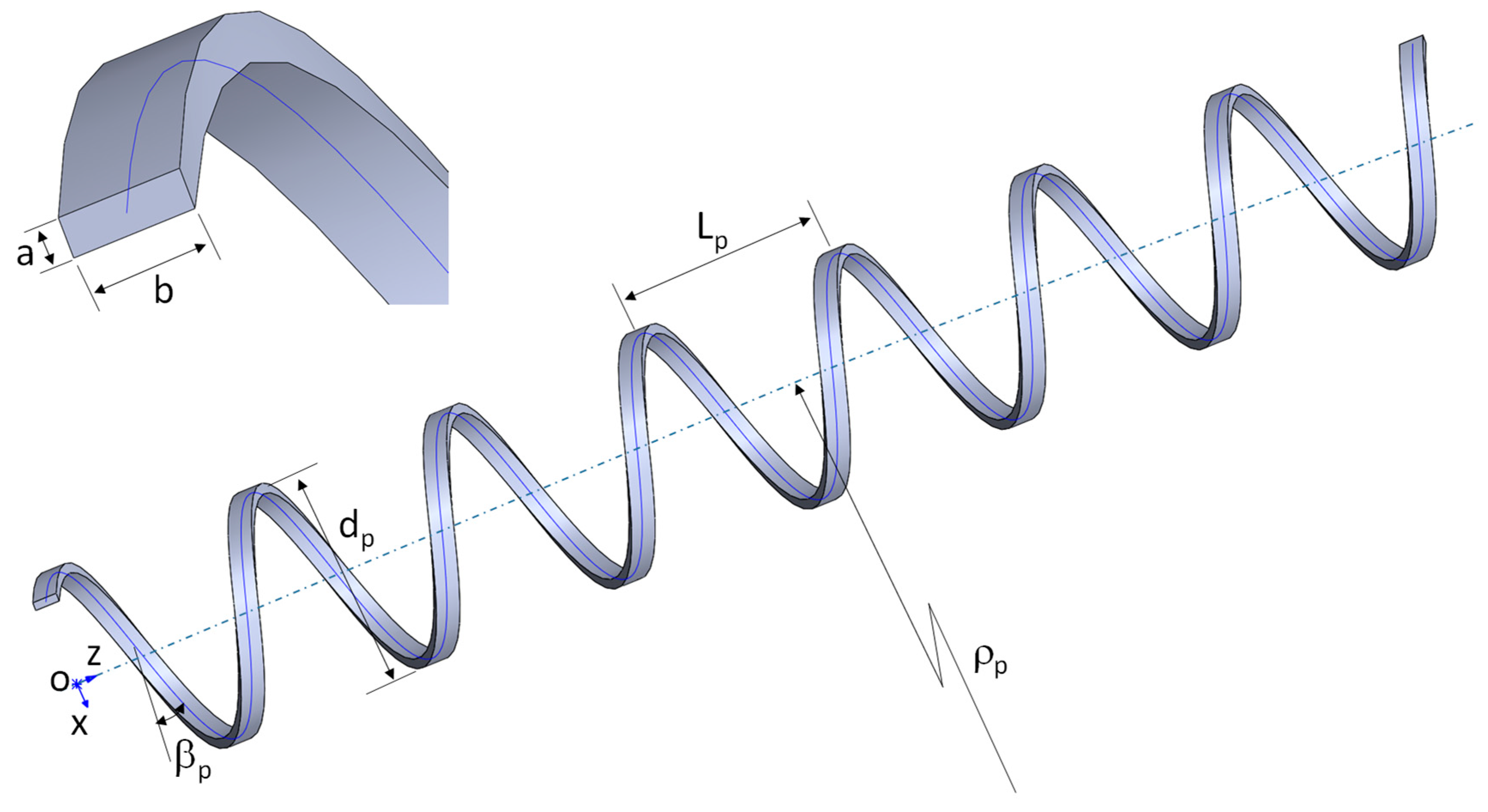
Figure 2.
Axial displacement under tension (FEA, T=10N).
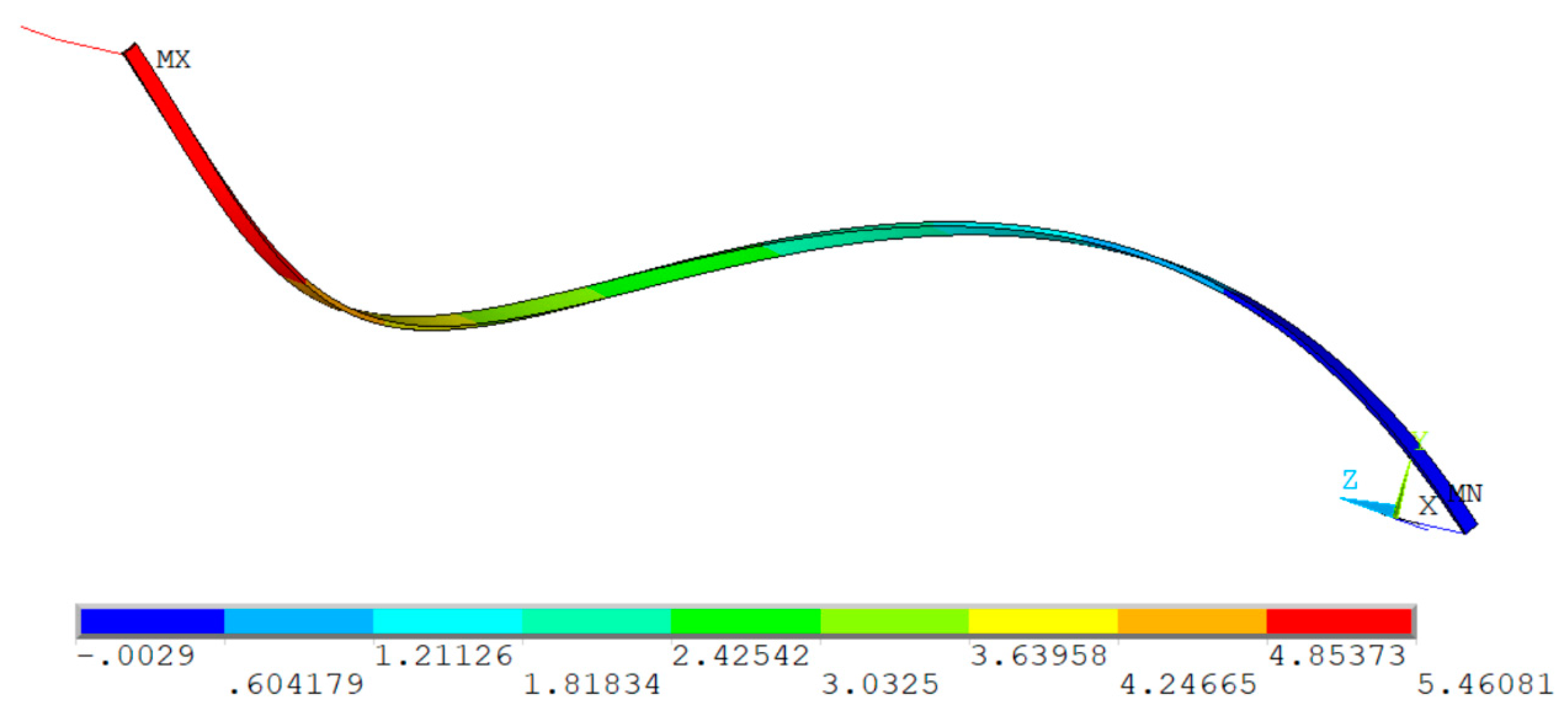
Figure 3.
Comparison of factor of .
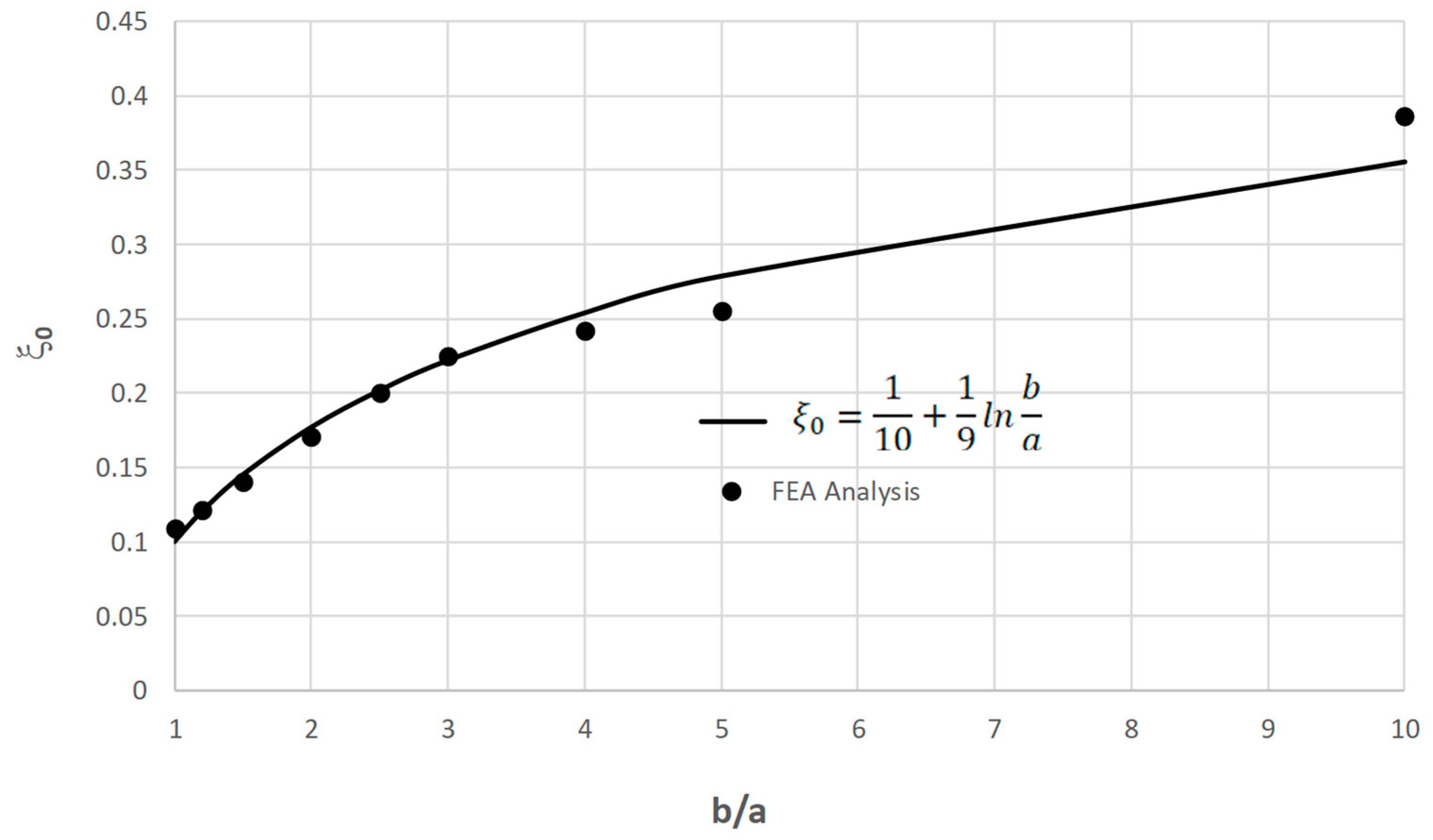
Figure 4.
Tensile armor lateral deflection under bending (M=10Nm ).
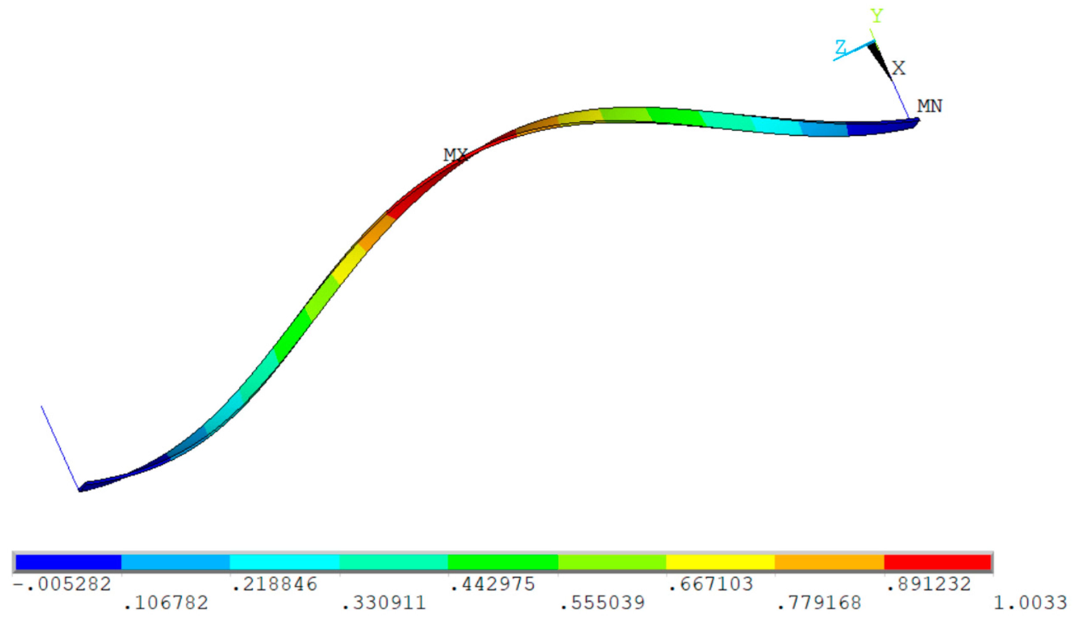
Figure 5.
Comparison of factor of .
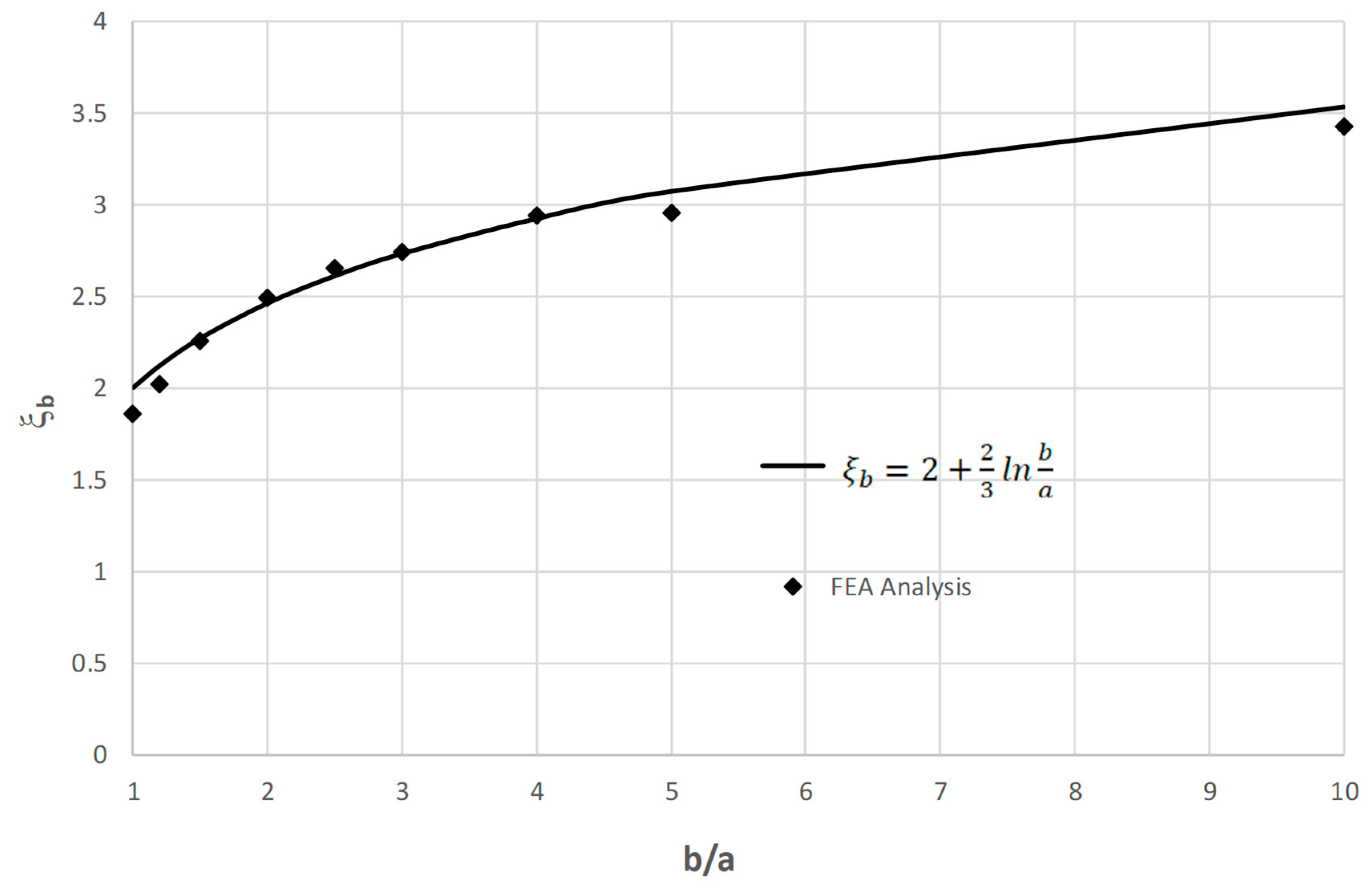
Figure 6.
Tensile armor tension-displacement hysteretic curve.
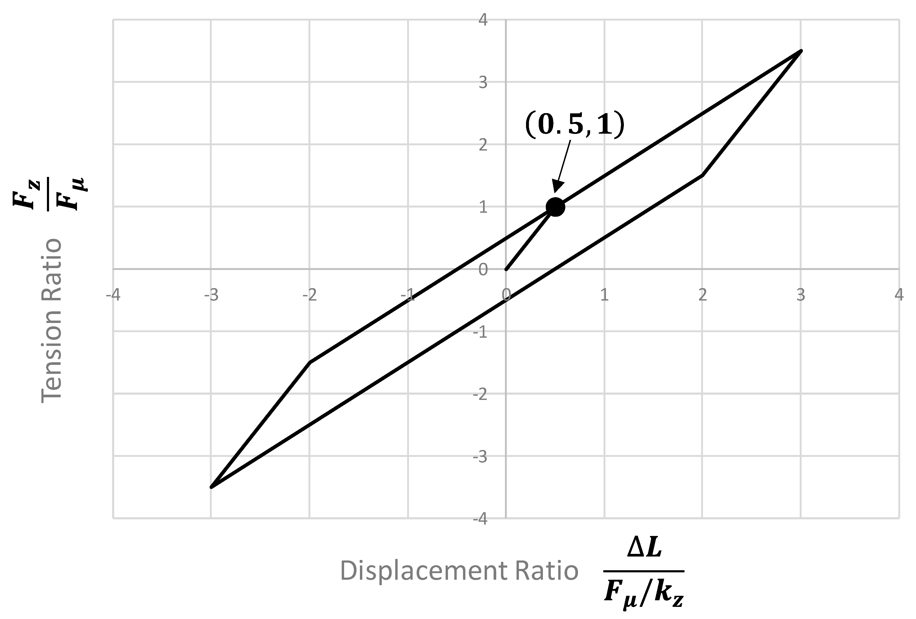
Figure 7.
Tensile armor bending moment – curvature hysteretic curve.
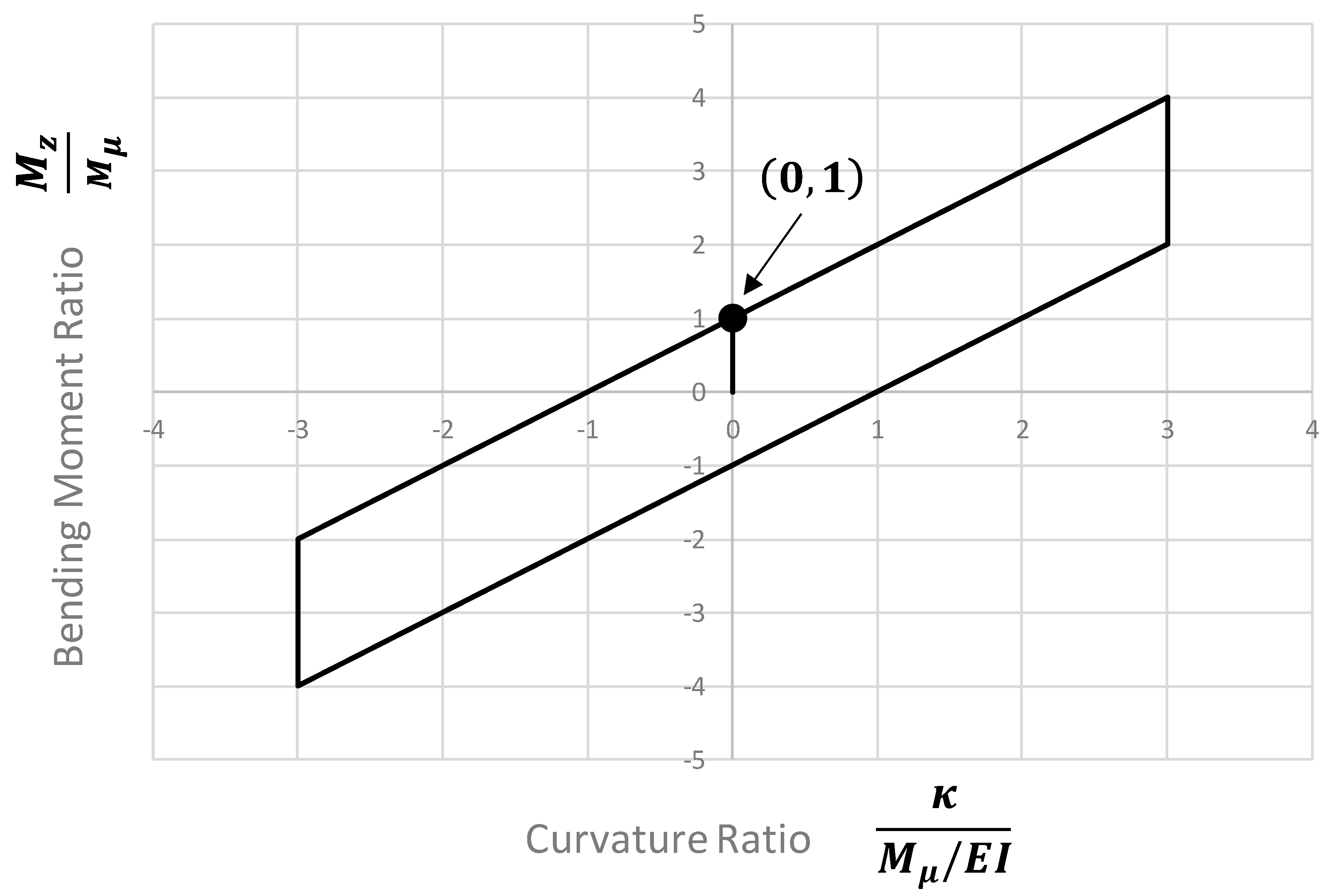
Figure 8.
Tensile stiffness testing sample.
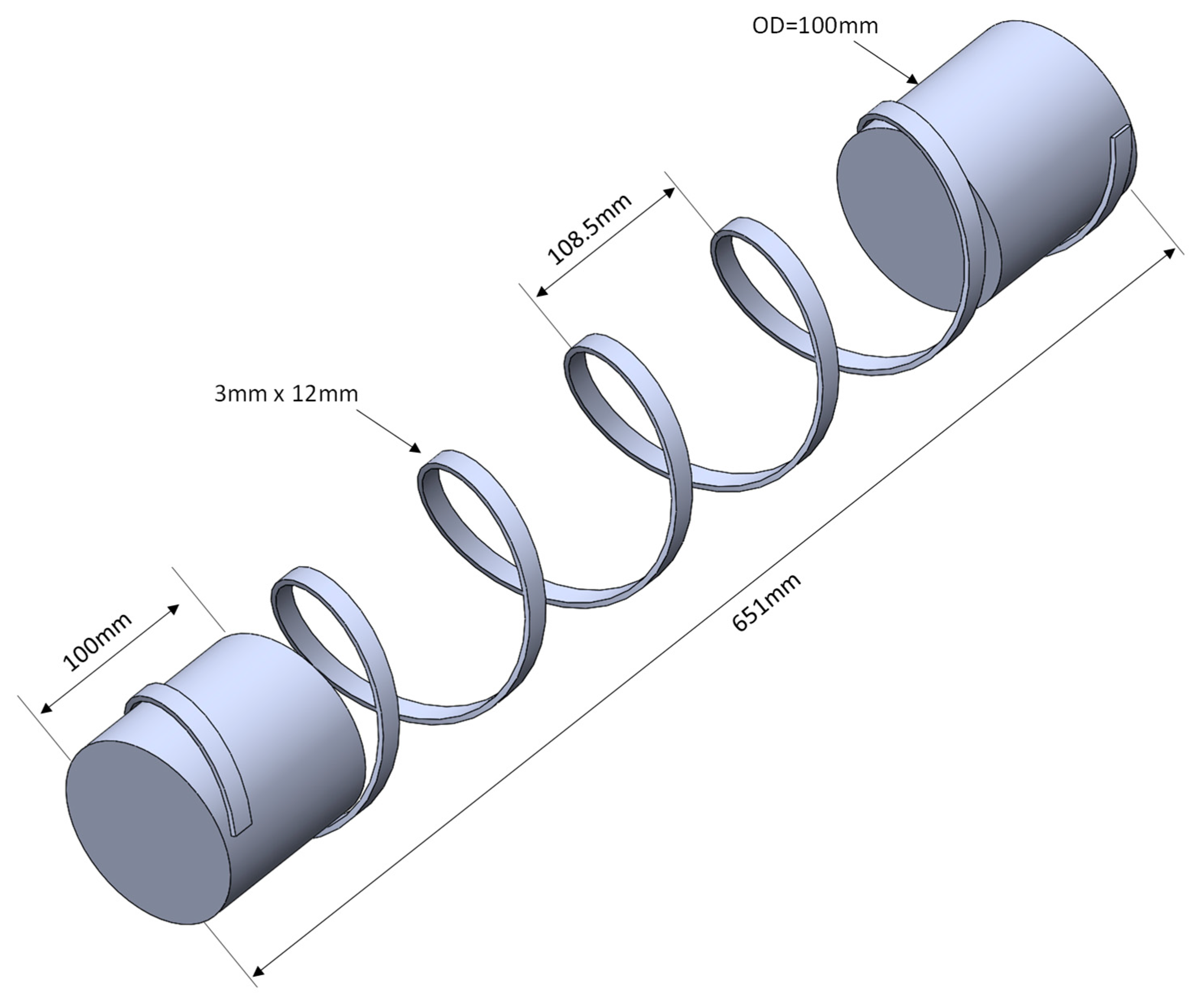
Figure 9.
Tensile stiffness comparison.
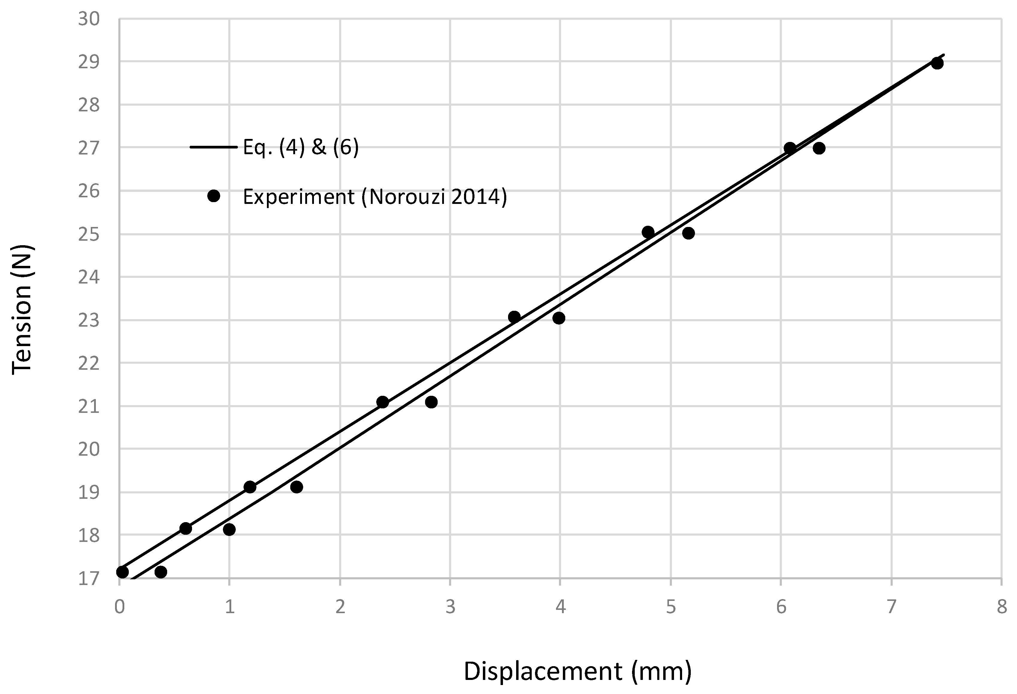
Figure 10.
Bending stiffness testing sample.
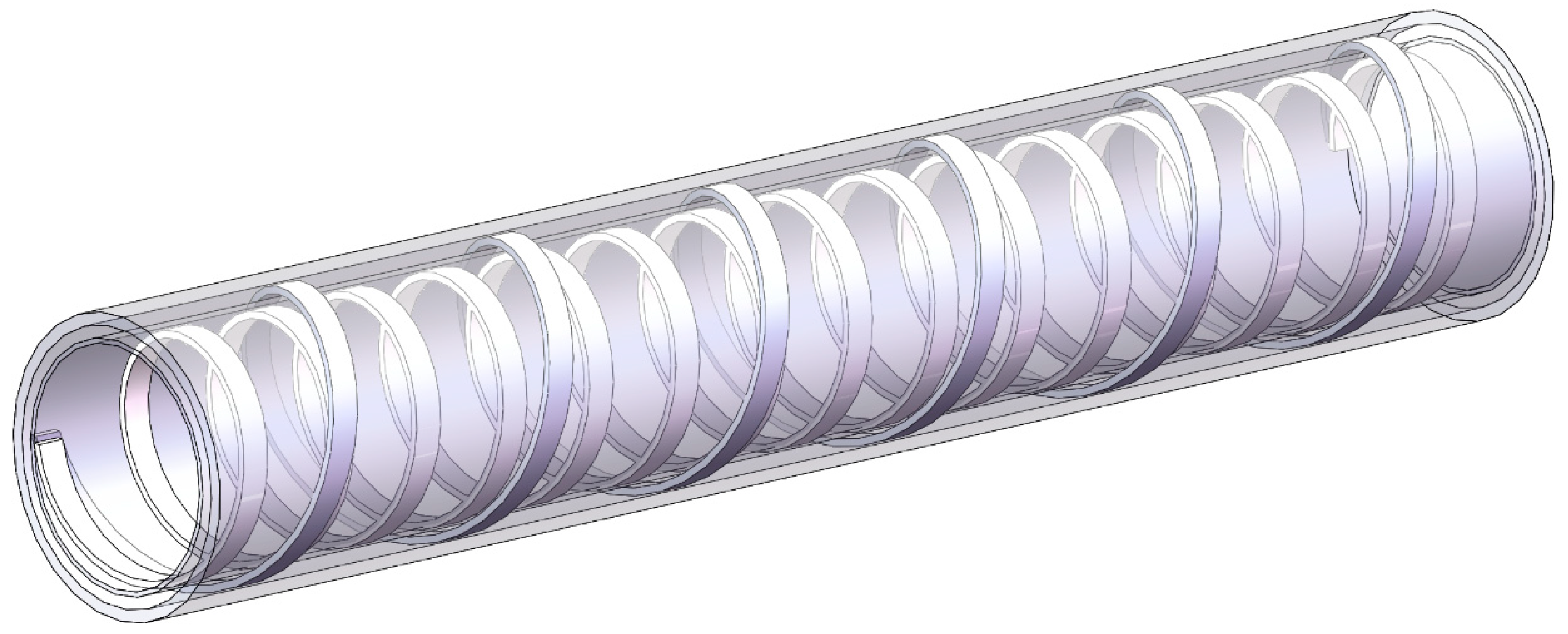
Figure 11.
Bending stiffness comparison.
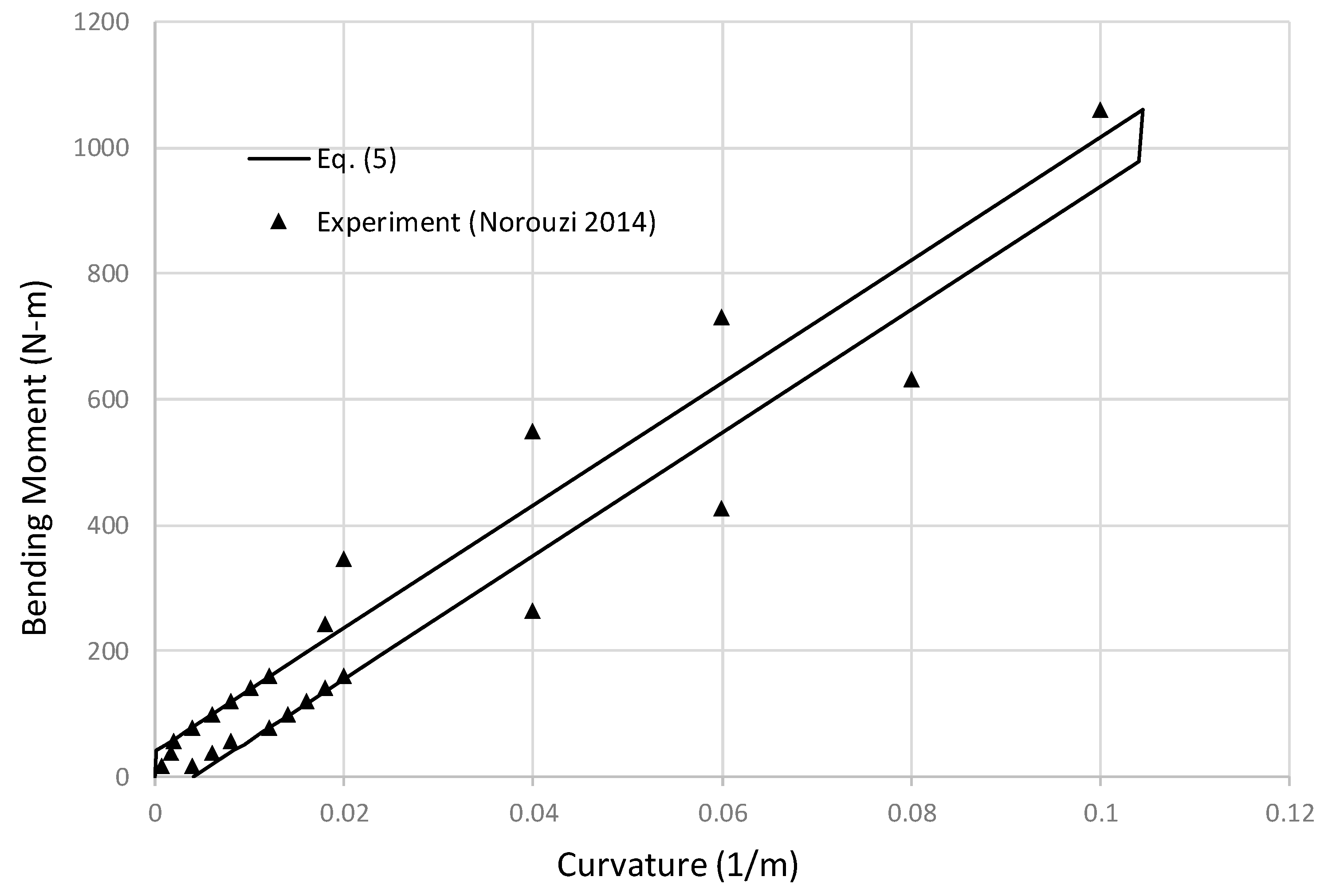
Figure 12.
LF13-2 subsea field layout.
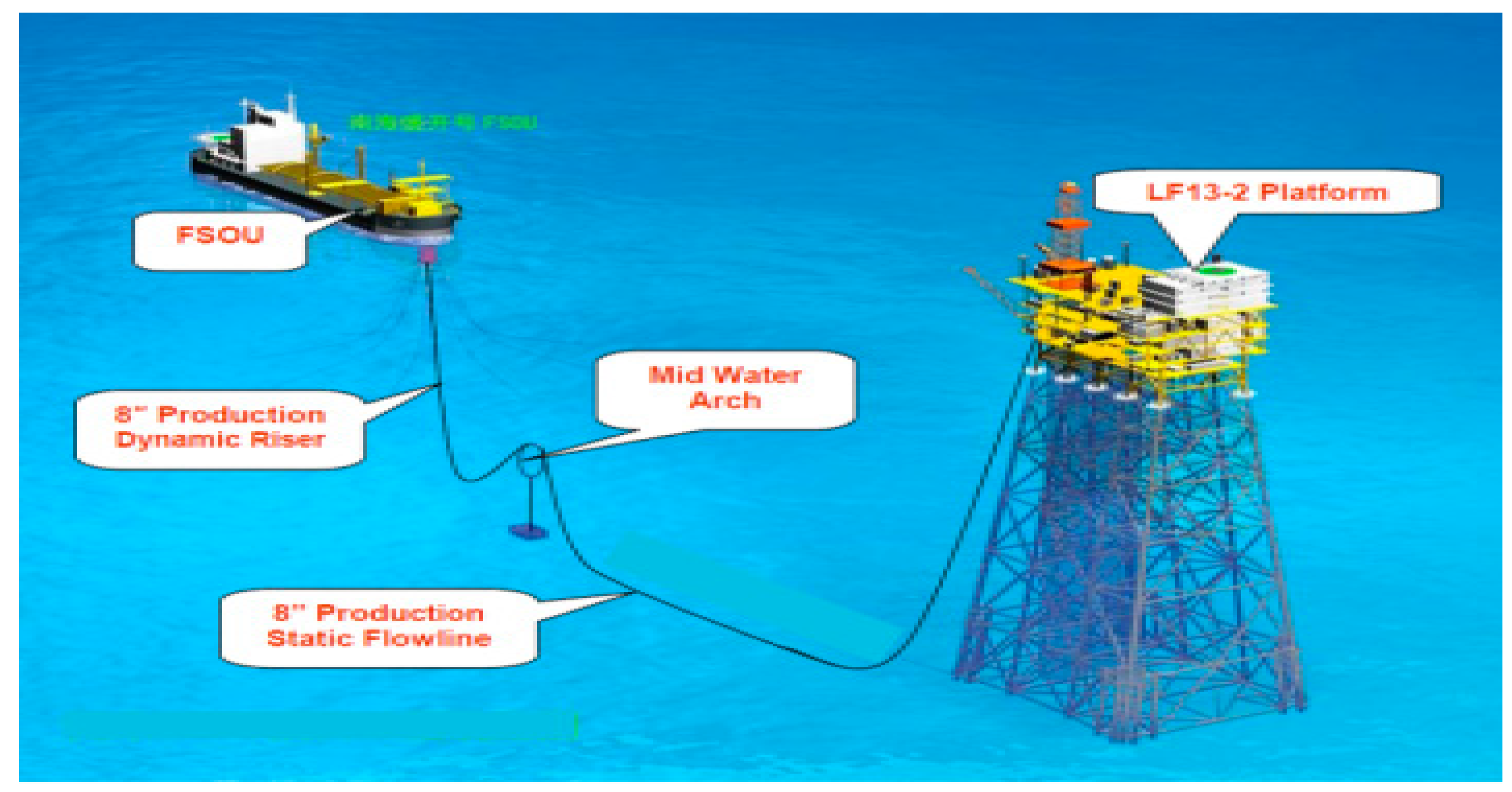
Figure 13.
Flexible riser general layout.
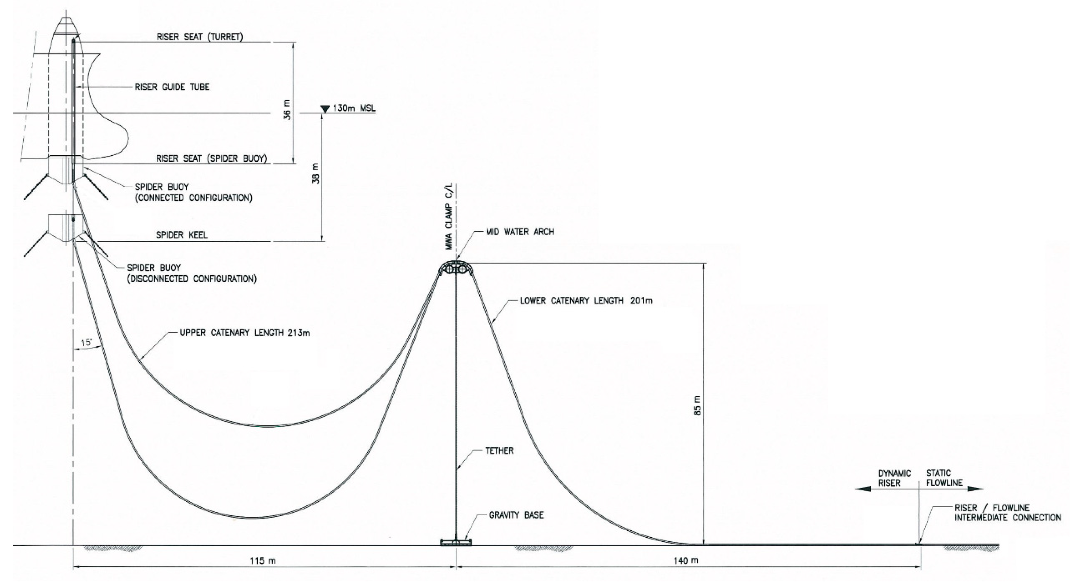
Figure 14.
Flexible riser structural layers.
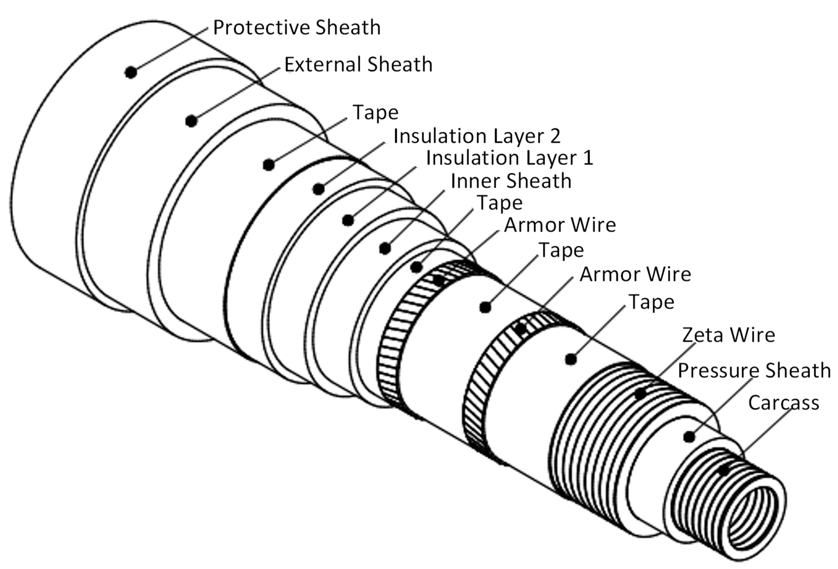
Figure 15.
Flexible riser dynamic response envelope (Hs=3m, Tp=8.5s).
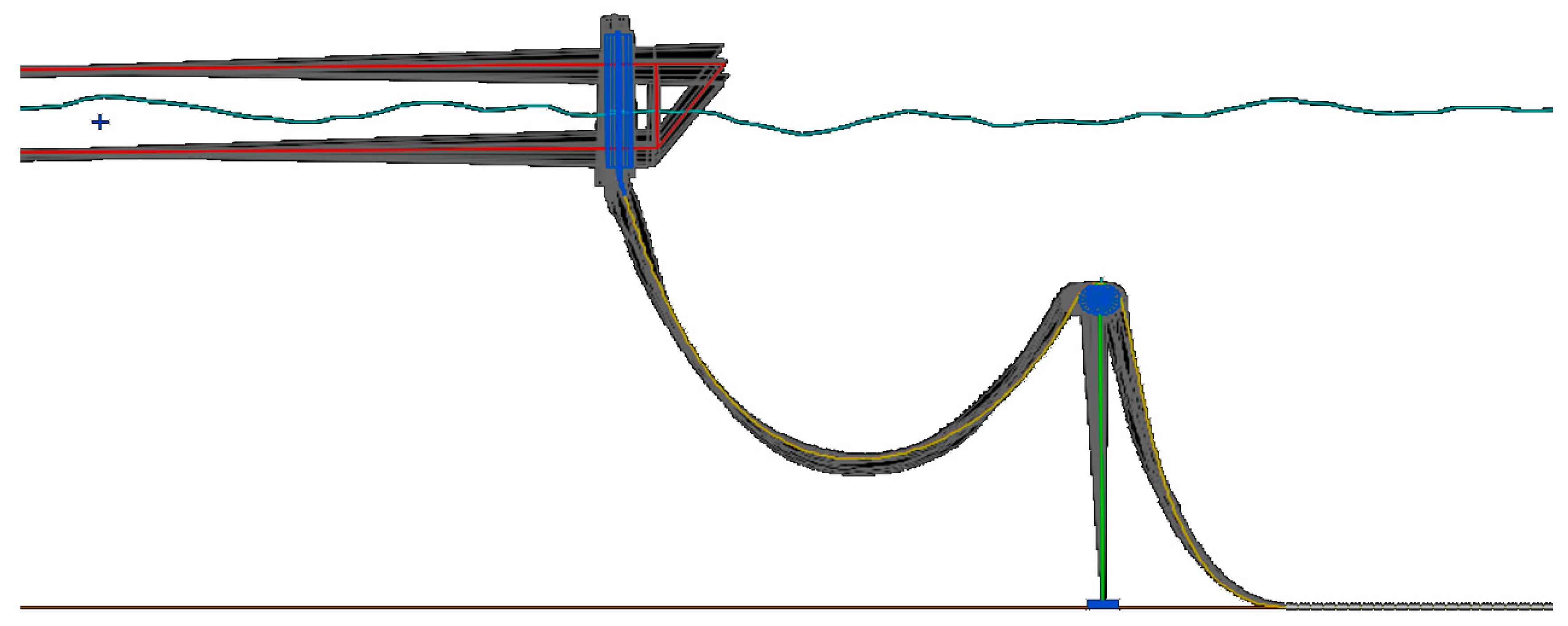
Figure 16.
Tension range distribution along the flexible riser (Hs=3m, Tp=8.5s).
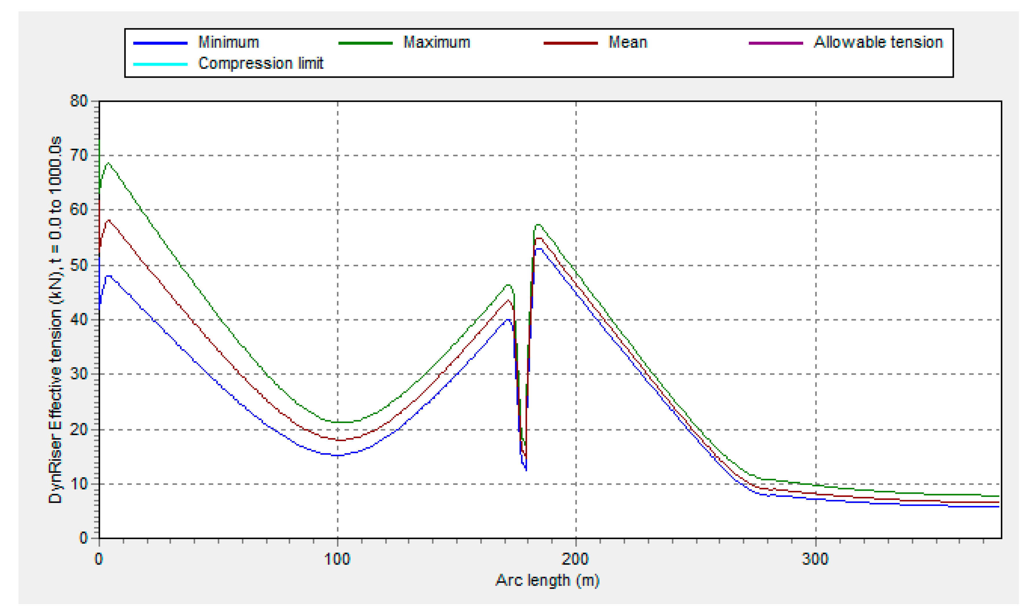
Figure 17.
Curvature range distribution along the flexible riser (Hs=3m, Tp=8.5s).
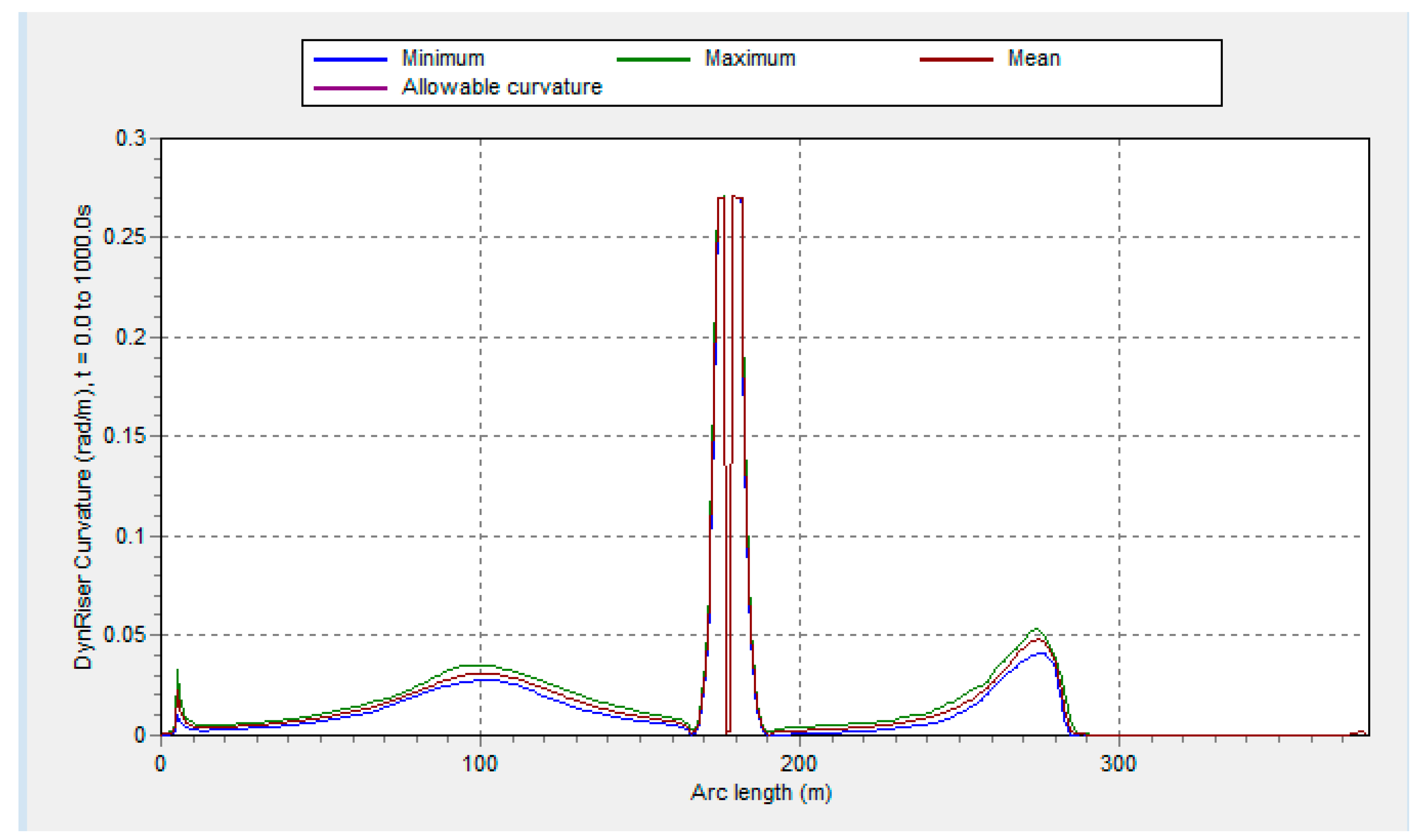
Figure 18.
Flexible riser FEA Model.
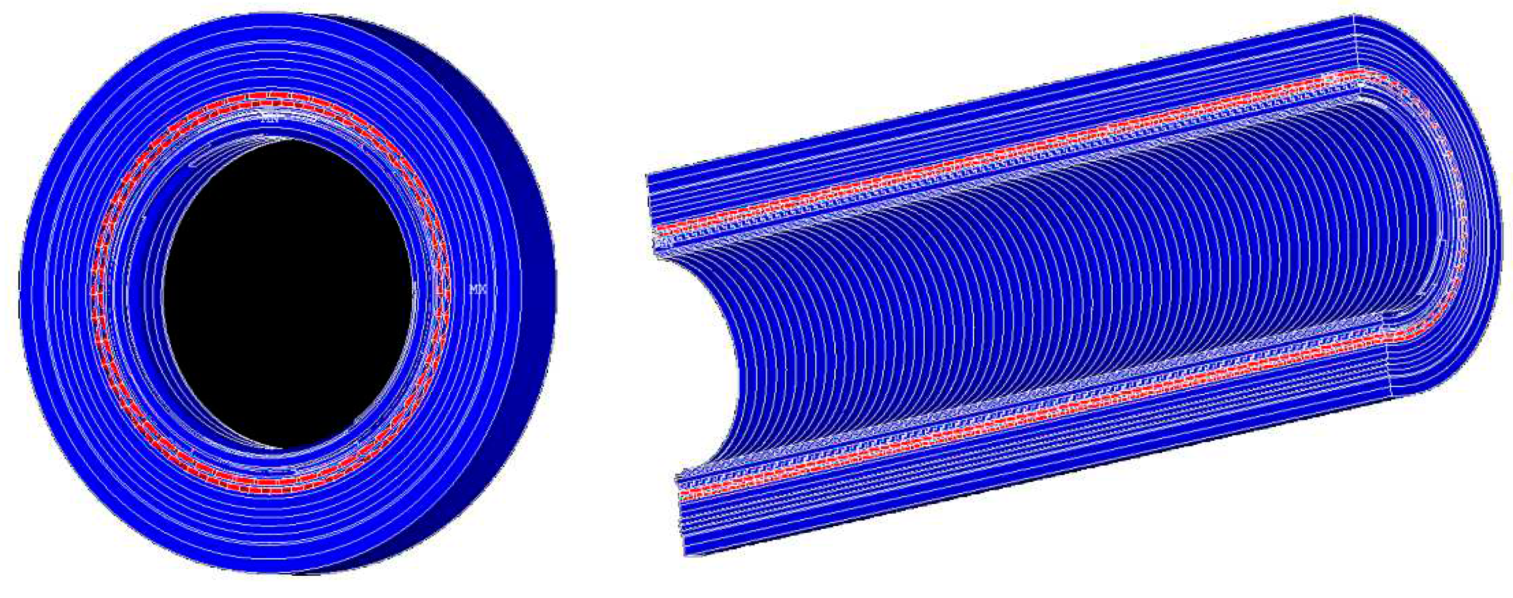

Table 1.
Factor of
| .b/a | 1 | 1.2 | 1.5 | 2 | 2.5 | 3 | 4 | 5 | 10 |
|---|---|---|---|---|---|---|---|---|---|
| (Eq) | 0.100 | 0.120 | 0.145 | 0.177 | 0.202 | 0.222 | 0.254 | 0.279 | 0.356 |
| (FEA) | 0.109 | 0.122 | 0.141 | 0.171 | 0.201 | 0.225 | 0.242 | 0.256 | 0.386 |
| Diff % | -8.8% | -1.1% | 2.9% | 3.5% | 0.5% | -1.2% | 4.6% | 8.3% | -8.5% |
Table 2.
Factor of
| b/a | 1 | 1.2 | 1.5 | 2 | 2.5 | 3 | 4 | 5 | 10 |
|---|---|---|---|---|---|---|---|---|---|
| (Wahl) | 0.208 | 0.219 | 0.231 | 0.246 | 0.258 | 0.267 | 0.282 | 0.291 | 0.312 |
| (FEA) | 0.205 | 0.220 | 0.231 | 0.245 | 0.258 | 0.267 | 0.282 | 0.292 | 0.312 |
| Diff % | -1.6% | 0.6% | -0.1% | -0.2% | -0.2% | 0.1% | -0.1% | 0.2% | 0.1% |
Table 3.
Flexible riser layer properties.
| Layer No | Layer Name | ID | Thickness | Mass | Tensile Strength |
| mm | mm | kg/m | MPa | ||
| 1 | Interlocked Carcass | 203.2 | 6 | 19.11 | 600 |
| 2 | Pressure Sheath Crossflex | 215.2 | 6 | 4.29 | - |
| 3 | Zeta Wire | 227.2 | 6.2 | 30.54 | 1000 |
| 4 | Anti-wear Tape | 239.6 | 1.5 | 1.08 | - |
| 5 | First Armor Lay | 242.6 | 4 | 21.7 | 1400 |
| 6 | Anti-wear Tape | 250.6 | 1.5 | 1.13 | - |
| 7 | Second Armor Lay | 253.6 | 4 | 22.66 | 1400 |
| 8 | High Strength Tape | 261.6 | 3.05 | 1.53 | - |
| 9 | Inner Sheath | 267.7 | 6.8 | 5.55 | - |
| 10 | Insulation Layer 1 | 281.3 | 11 | 5.15 | - |
| 11 | Insulation Layer 2 | 303.3 | 11 | 5.53 | - |
| 12 | Fabric Tape | 325.3 | 1.4 | 0.86 | - |
| 13 | External Sheath | 328.1 | 9.1 | 9.13 | - |
| 14 | Protective Sheath | 346.3 | 9.1 | 9.62 | - |
Table 4.
Tensile armor maximum stress comparisons.
| Case | Eq. (8) | FEA Model | Difference % |
|---|---|---|---|
| Tension=5Te Curvature=0 |
8.2MPa | 7.8MPa | 3.8% |
| Tension=0 Curvature=0.05rad/m |
81.1MPa | 83.5MPa | -2.9% |
| Tension=5Te Curvature=0.05rad/m |
88.3MPa | 90.8MPa | -2.8% |
Table 5.
Summary of tensile armor fatigue damage results.
| Item | Unit | Hang Off Section | Sag Bend Section | Hog Bend Section | Touchdown Section |
|---|---|---|---|---|---|
| Nanhaishengkai FSOU (2782 days) | 1/y | 2.78E-04 | 9.25E-09 | 1.43E-06 | 2.84E-08 |
| HYSY121 FSOU (469 days) | 1/y | 5.97E-05 | 1.43E-09 | 1.65E-07 | 4.60E-09 |
| Turret Disconnected (237 days) | 1/y | 2.21E-07 | 7.59E-11 | 8.88E-09 | 4.18E-09 |
| Total Fatigue Damage | 1/y | 3.38E-04 | 1.08E-08 | 1.61E-06 | 3.72E-08 |
| Safety Factor | 10 | 10 | 10 | 10 | |
| Remaining Fatigue Life | y | 2.14E+03 | 9.01E+07 | 7.79E+05 | 1.55E+07 |
Disclaimer/Publisher’s Note: The statements, opinions and data contained in all publications are solely those of the individual author(s) and contributor(s) and not of MDPI and/or the editor(s). MDPI and/or the editor(s) disclaim responsibility for any injury to people or property resulting from any ideas, methods, instructions or products referred to in the content. |
© 2023 by the authors. Licensee MDPI, Basel, Switzerland. This article is an open access article distributed under the terms and conditions of the Creative Commons Attribution (CC BY) license (http://creativecommons.org/licenses/by/4.0/).
Copyright: This open access article is published under a Creative Commons CC BY 4.0 license, which permit the free download, distribution, and reuse, provided that the author and preprint are cited in any reuse.