
Submitted:
04 July 2023
Posted:
04 July 2023
You are already at the latest version
Abstract
Nowadays, with the development of laser weapons, the primary power supply of laser weapons puts forward more and more high demand for its performance. The pulsed power supply based on conventional homopolar inductor alternator (HIA) cannot meet the requirements any more. In order to improve the power density and efficiency, this paper proposes applying the high-temperature superconducting (HTS) HIA with slotless stator core to this power supply. In this paper, the design considerations of it are presented, and the comparisons between the two power supplies are discussed. The calculation results show that the power supply based on HTS machine has much larger power density than the conventional HIA, and the efficiency is also larger than the conventional HIA. This can improve the performance of laser weapons dramatically.
Keywords:
homopolar inductor alternator
; high temperature superconductivity
; capacitor charge power supply
1. Introduction
The high-power pulsed power supply (PPS) based on homopolar inductor alternator (HIA) was successfully used for the primary power supply of laser weapons. This type of power supply has the advantage of high power density and high reliability. The design and test of capacitor charge power supply (CCPS) based on HIA are discussed in references [1-12]. In the design of this power supply, the efficiency of the power supply is an important parameter, and the analysis and testing result of efficiency of this power supply are presented in reference [9]. The theory [13, 14], the parameter calculation [15], the magnetic field analysis, the calculation models [16-20] and optimal design methods [1, 7, 9, 10, 12, 21-24] for HIA have been studied in many literatures.
At present, the issue of efficiency is still serious for the CCPS, which results in enormous temperature rising, and reference [25] proposed a novel hybrid thermal network for homopolar inductor machine. The theoretical calculation and the testing results in reference [9] show that the armature copper loss accounted for the largest proportion of total loss, and the iron loss takes the second proportion. The large armature copper loss is due to the squeezing effects and skin effects. The large iron losses are caused by the very high electrical frequency, and the rotor eddy-current losses induced by the air-gap tooth-tip harmonic field, and the relative movements between rotor and the magneto motive force (MMF) produced by armature currents [8-9, 26-28].
On the other hand, the inner reactance of HIA is usually big, due to the relative small air-gap length and the considerable slot and tooth-tip leakage inductances, and the fundamental air-gap magnetic field is relative low due to the lower magnetic field utilization when compared with other conventional machines, which limits further improvements of the output power.
Nowadays, with the development of laser weapons, the primary power supply of laser weapons puts forward more and more high demand for its performance. For the reasons presented above, the power density and efficiency of CCPS based on the conventional HIA cannot meet the requirements any more, which has dramatic effect on the performance of laser weapons, especially the continuous emission capacity.
The multistage stator cores HIA with bipolar air-gap flux density is proposed in references [29-31], which can enlarge the power and energy storage capacity of the HIA prominently, but for the efficiency the promotion is insufficient.
In order to improve the power density and the efficiency of the CCPS simultaneously, the high-temperature superconducting (HTS) HIA is proposed applying to the PPS. The HTS HIAs used for marine application, airborne generator and energy storage are studied in references [32-35].
The HIA proposed used for the CCPS is a slotless stator-core HTS excited alternator with much higher air-gap magnetic flux density and lower inner reactance and the squeezing and skin effects of armature winding are much less serious than conventional HIA, which makes the machine with much higher power density and efficiency.
The structure of the paper is as follows. In the first part, we briefly introduce the CCPS based on a conventional prototype HIA. In the second part, the main design considerations of the slotless stator-core HTS HIA used for the CCPS are presented.
In the third part, A HTS HIA is designed for the CCPS, and the finite element simulation is used to verify the designed results. Finally, the comparisons between the two CCPSs are discussed, and the comparisons mainly focused on the charge power and efficiency.
2. Introduction of CCPS based on Conventional HIA
2.1. Brief introduction for CCPS based on HIA
As shown in Figure 1, the system structure diagram is presented for the high-power PPS based on HIA. The prime motor drives the high-voltage HIA; and the high-voltage generator charges the capacitor through a half-controlled rectifier quickly and respectively. The HIA is applied to this system, to meet the requirements of repetition pulse charge, due to its advantage of high energy storage density. The kinetic energy of the rotor is converted to electrical energy to be stored in the capacitor during the charge process [7, 9, 10, 12].
HIA is a variable reluctance machine with a toothed revolving rotor [1, 7, 9, 10, 12], as illustrated in Figure 2. Both the armature and field winding of it are on the stator, and the stationary field winding is a toroidal winding coaxial with the rotor. The stator core and the rotor core are both composed of two parts named as left part and right part, the axes of the left part and right part stagger 180° electrical angle in space. The field current produces homopolar flux in the air gap. The periodic change of flux linkages caused by the modulation generates an induced voltage in the stationary armature winding.
The rectifier for the CCPS is a three-phase semi-controlled full bridge which can be regarded as an uncontrolled full bridge as shown in Figure 3, because the trigger signals of the thyristors are always turned on during the charge process. The capacitor is 7.8 mF nearly. The electrical energy stored in the capacitor is about 75 kJ when the capacitor voltage rises to the predicted value.
2.2. The parameters of CCPS based on conventional HIA
The parameters of HIA are shown in Table 1 and the pictures of rotor are shown in Figure 4 [9, 10]. The CCPS based on the prototype HIA has the performance parameters as follows:
- The charge repetition frequency is 20 Hz,and the maximum repetition number is 60;
- The maximum charge time is less than 35 ms when the predicted charge voltage is 4400 V;
- The charge efficiency is 75% to 80%.
3. Design Considerations of HTS HIA for CCPS
Because the copper loss of field coil for the HTS HIA is zero, the MMF produced by the field coil can be designed to be very large which means a very large air-gap length. So the air-gap armature winding can be adopted, which means the stator core is slotless [21, 32, 35]. The air-gap winding has brought many benefits for HIA, as following. Firstly, the loss of HTS HIA is much less than the conventional HIA, the reason is as follows.
- The tooth-tip harmonic MMF is eliminated and the rotor eddy-current losses caused by tooth-tip harmonic MMF are zero.
- Due to the slotless stator core, the extremely serious squeezing effects in the conventional HIA are eliminated. So the armature windings copper losses of HTS HIA are much less than the conventional HIA.
Secondly, the power density of HTS HIA is much larger than the conventional HIA, the reason is as follows.
- The air-gap magnetic field intensity for HTS HIA is larger than the conventional HIA due to the slotless stator core.
- The armature reaction reactance of HTS HIA is much less than the conventional HTS due to the much larger air-gap length. Meanwhile, the slot and tooth-tip leakage inductances are also eliminated, so the sub-transient reactance of HTS HIA is much less than conventional HIA.
For the reasons presented above, the design considerations of the HTS HIA for the CCPS have some differences with the conventional HIA which is presented in references [1, 7, 10, 12]. Mainly, the considerations of the ratio of main dimensions, the air-gap length and the windings parameters for HTS HIA have some differences with the conventional HIA.
The design flow of HTS HIA for CCPS is presented in Figure 5. The detailed considerations are presented in the following sections.
3.1. The ratio of main dimensions
Because the power density of HTS HIA is much larger than conventional HIA, the target for the energy storage is taking precedence over the power for the HTS HIA rather than that the energy storage and power should be both covering for the conventional HIA. The energy density for the rotor of HIA is [1]:
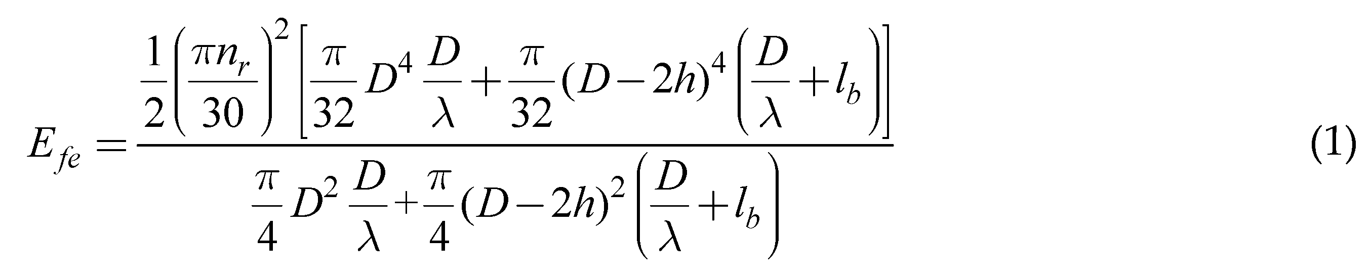
Here, λ is the ratio of rotor diameter to length and the definitions of other symbols are presented in Table 2. We can conclude that the larger the ratio of rotor diameter to length is, the larger the energy density is.
So, for the HTS HIA, the ratio of rotor diameter to length should be as large as possible to achieve the largest energy density. But on the other hand, there is a maximum rotor diameter for a given rotating speed, in order to ensure that the rotor strength is in security zones, as shown in Eq. 2. The main dimensions of HTS HIA are decided in the following steps:
- First, the rotor diameter is decided by Eq. 2;
- Then, the rotor length is decided by the energy storage required, when the parameter lb is given, as shown in Eq. 3. The rotor energy storage required is estimated by the energy stored in the capacitor on the condition that the charge efficiency is about 80%.
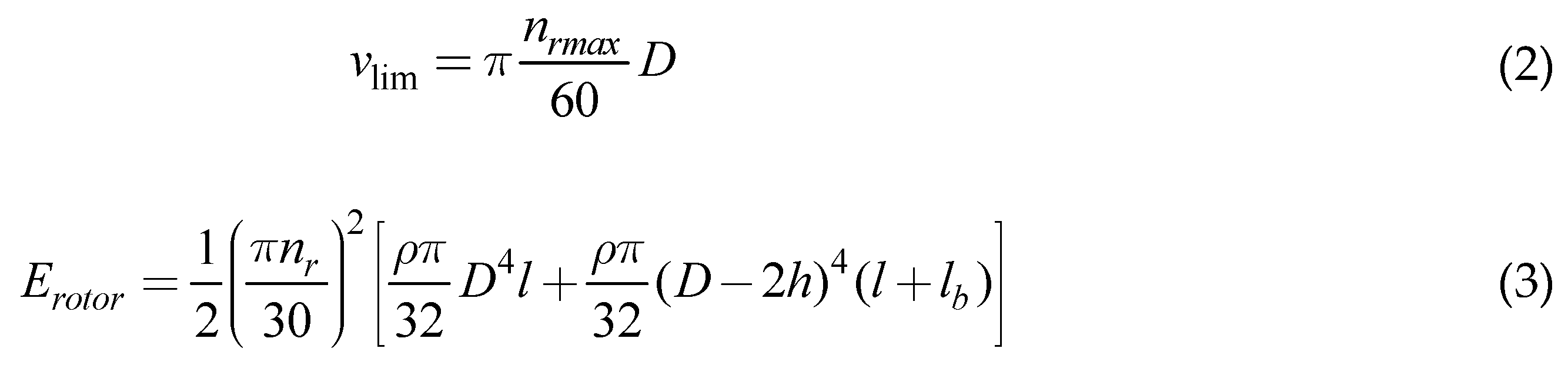
The vlim is the limiting value of rotor tip speed, and ρ is the mass density of rotor.
3.2. Windings parameter
Like the conventional HIA for CCPS, the number of series turns per phase is determined by the no-load induced electromotive force (EMF) value, and the amplitude of no-load line-to-line induced EMF value is chosen to be 1.1-1.3 times of maximum predicted capacitor charge voltage. The considerations of short-pitch and the distributed windings for the HTS HIA are similar for the conventional HIA, which are presented in references [8, 9].
But the air-gap winding structure for HTS HIA is very different from the winding for the conventional HIA, which cause some difference for considerations of wingding parameters between the HTS HIA and the conventional HIA. Unlike the conventional HIA, the single-layer windings are chosen for the HTS HIA, considering reducing the isolation difficulty as much as possible, and that due to slotless iron core, there is no need to employ the double-layer windings to relieve the extremely serious squeezing effects in the conventional HIA.
3.3. Air-gap length
For the conventional HIA, due to the limitation of MMF of field coil, the air-gap length cannot be chosen arbitrarily large, and what’s more the rotor shaft flux density would be saturated if the air-gap length is too large, for the reason that the rotor slot depth would be too large so the diameter of rotor shaft would be very small.
Unlike the conventional HIA, because the ratio of rotor diameter to length is very large, the rotor shaft flux density is not saturated. And on the other hand the MMF of field coil is very large. So, the air-gap length would not be limited by the factors in the conventional HIA. For the HTS HIA, the air-gap length is determined by the dimensions of armature windings. The air-gap length is equal to the sum of the thickness of armature windings including isolation thickness and the physical air-gap length between armature winding and rotor.
3.4. Rotor dimensions
The design considerations of rotor dimensions for HTS HIA are similar to conventional HIA. The rotor dimensions include the diameter and length, the rotor slot depth h, the rotor slot width, the pole pair number of rotor. The considerations of rotor slot depth, rotor slot width mainly consider the fundamental component of air-gap magnetic field, and the conclusions are presented in references [1, 7, 10, 12, 17, 24]. The considerations of pole pair number mainly consider the axial length, the inner reactance, the rotor eddy-current losses, and maximum operating frequency of the semi-conductive device of rectifier, which are presented in reference [9, 10].
3.5. HTS field coil
The immobile field coil of HIA does not sustain the huge centrifugal forces that a rotating coil would suffer. What’s more, because the coil can be an uncomplicated solenoid around the rotor rather than a more complex racetrack type coil, the coil support can be much easier.
The required magnitude of MMF produced by the field current is determined by:

Ff is the magnitude of MMF produced by the field current, δ is the air-gap length, μ0 is permeability of vacuum, Bδ is maximum air-gap magnetic flux density, and Ks is the saturation factor of magnetic circuit. In order to achieve the as large power density as possible, the air-gap magnetic flux density is designed to be about 1.6 T.
For a given exciting window, the efficient area of the exciting window is determined, that’s to say the maximum ampere turns of exciting coil is determined. So the dimensions of the exciting window are determined by the ampere-turn number of the field coil, in other words the required magnitude of MMF produced by the field current.
The YBCO-coated conductor made by the Shanghai Superconductor company is used for the field coil. The cross-section dimensions of the YBCO-coated conductor are 0.1mm×10mm, and the thickness of the isolated layer between the YBCO-coated conductors is designed to be 0.1 mm. The YBCO-coated conductor operating temperature is designed to be 40 K, and at 40 K the critical current is about 600 A on the condition of magnetic flux density of 0.9 T. The maximum (rated) field current is decided by the YBCO-coated conductor critical current multiplying a safety factor.
3.6. Cryogenic system
Due to the deficient of centrifugal loads and reduced needs on the coil support, the thermal insulation between the ambient and the field coil is also improved. What’s more, the cryostat of the coil is static. There is no need for a transfer coupling to lead a cooling medium into the rotating cooling circuit. Instead, the coil can be refrigerated by one of the established and more reliable methods of refrigeration, such as conduction cooling. As needed for good heat insulation, the vacuum or foam insulation will be static and therefore more reliable. And also, other parts of the insulation scheme can also be made more credible without the huge gravity forces.
Like the methods in reference [33], the HTS field coil is refrigerated by the boiling liquid neon through a cooling-tube heat exchanger. The heat exchanger is in contact with the coil outside surface. The return boil off neon is re-condensed by a single GM cryocooler. The cryocooler and cryogen re-condenser unit are installed on the top of the HIA in an easy and robust assembly, and the liquid neon is driven by gravity. The vacuum is used to thermally insulate the HTS field coil, and the total heat load is about 55 W. This refrigerator load needs a single-stage GM coldhead with capacity larger than 70 W at 25 K.
4. Simulation results and comparison of two CCPSs
The designed parameters of HTS HIA for CCPS are shown in Table 2. The parameters of electromagnetic properties are shown in Table 3. The rotor material is 300M alloy steel, which has a tensile strength up to 1860 MPa. The soft magnetic alloys are used for the shell materials; the designation of Fe-Co alloy is 1J22. This material has very high saturation magnetic induction intensity, up to 2.4 T; this can decrease the thickness of shell substantially. The turn number of the HTS field coil is 60, and the designed maximum (rated) field current is 432 A.
The parameters of electromagnetic properties shown in Table 3 are calculated by analytical methods, and the air-gap permeance used in the analytical methods is obtained by look-up table. The look-up table is obtained by two-dimensional FEM simulation model in advance. The detailed description of this two-dimensional FEM model is presented in reference [1, 12, 15].
4.1. The simulation results of HTS HIA
4.1.1. Electromagnetic performance verification
The three-dimensional FEM simulations are used to verify the electromagnetic calculation results in analytical methods. The two-dimensional air-gap magnetic induction intensity distribution is shown in Figure 6 (a), and the air-gap flux density distribution along rotor position at different position is presented in Figure 6 (b). It can be found that the maximum value of air-gap flux density is about 1.6 T, and the axial distance has little effects on the distribution of air-gap flux density along rotor position. The simulated magnetic flux density distribution on rotor is shown in Figure 7, and it can be seen that the maximum magnetic flux density on the rotor tooth face is about 2.0 T. While in the rotor inner region, the magnetic flux density is very small.
The simulated waveforms of no-load induced phase EMF and line-to-line EMF are shown in Figure 8. The distributed windings can decrease the high-order harmonic components of EMF in the windings, such as 5, 7 and so on. Though the 3 times harmonic component cannot be reduced by distributed windings significantly, there phase angles are the same. So there is no 3 times harmonic component in the line-to-line EMF, as shown in Figure 8 (b). The amplitude of no-load induced line-to-line EMF is about 6.1 kV, which is approximate to the designed value.
The simulated magnetic induction intensity distribution in the field coil region is presented in Figure 9. It can be found that the maximum magnetic induction intensity is at the inside of the field coil, and the maximum magnetic induction intensity is about 0.896 T, which is not larger than the designed value. So the HTS field coil can operate in the safety region.
4.1.2. Rotor strength verification
The three-dimensional FEM simulations are used to verify the rotor strength. The simulation results of rotor stresses and deformation at 6000 rpm are presented in Figure 10 (a) and Figure 10 (b) respectively. It can be found that the maximum rotor stresses is about 412 MPa, which is much less than the tensile strength of 300M alloy steel. So, the rotor strength is enough. The maximum radial deformation of rotor is about 0.3 mm, which is much less than electromagnetic air-gap length, and this means the deformation of rotor has very little effects on the electromagnetic performance of HIA. Also the maximum radial deformation of rotor is less than the physical air-gap length which is 1.5 mm, and this means there are no risks of stator and rotor of friction.
4.2. The comparison of two CCPSs
The three-dimensional models of two HIAs for CCPS are presented in Figure 11. It can be seen that the HTS HIA has the flat shape. This is because that, for the HTS HIA, the prime consideration is to obtain the as large energy density as possible, while the power density is secondary to energy density. The comparison of two CCPSs is presented in Table 4. It can be seen that, the maximum rotating speed of HTS HIA is much less than the conventional HIA, and the electrical frequency of HTS HIA is less than the conventional HIA. The lower rotating speed brings about many benefits for the machine, such as lower difficulty for selecting bearings, lower losses, and lower noise and so on.
Because the sub-transient reactance of HTS HIA is less than the conventional HIA, the power of HTS HIA is larger than the conventional HIA. The great advantage of HTS HIA is that, the total weight of HTS HIA is much lighter than the conventional HIA, and this is a very important factor for laser weapons. As shown in Table 4, the total weight of HTS HIA (including the cryogenic system) is about 20% lighter than the conventional HIA.
4.2.1. Charging power and time
The equivalent discharge-inductance model for HIA with rectifier and an extremely large capacitor as shown in Figure 3 is used to simulate the charge performance. Meanwhile, a two-dimensional FEM model combined with the equivalent discharge-inductance circuit model is used for calculating the rotor eddy-current losses, which is proposed in the references [8-9].
Because for the first pulse (#1), the amplitude of no-load induced EMF of HIA is the maximum value among all pulses, it is the easiest to archive the predicted charge voltage. So the last pulse (#60) is taken into consideration. For the last pulse, the rotating speed of HTS HIA and conventional HIA at the end of last pulse is assumed both to be 0.8 times of initial speed, that’s to be 4800 rpm and 8000 pm respectively, and it is assumed that the rotating speed is constant during one pulse. The simulated waveforms of charge current and voltage are shown in Figure 12, and as comparison the results of conventional HIA is also presented. The simulation results show that amplitude of charge current for the CCPS based on the HTS HIA is much larger than the CCPS based on the conventional HIA, and the required charge time for the CCPS based on the HTS HIA is much shorter than the CCPS based on the conventional HIA, and this means the CCPS based on the HTS HIA has much larger charge power than the conventional HIA. As shown in Table 4, the average charge power for CCPS based on conventional HIA is 2.14 MW, while for the HTS HIA the value is 1.75 times of conventional HIA, to be 3.75 MW.
4.2.2. Charging efficiency
What’s more, the charge efficiency of CCPS based on the HTS HIA is 6.7% larger than the conventional HIA. The efficiency of CCPS is calculated by:

Here, EC is the energy stored by the capacitor; Eloss is the energy losses during the one charge process. The detailed calculation methods for losses are presented in reference [9]. It should be pointed out that, the calculation of iron core losses in this paper makes some improvements, and they are calculated by the no-load iron core losses multiplying a factor which takes the effects of armature reaction magnetic field into consideration. The factor is determined by compromising between the twice 3D FEM simulations, where the armature currents amplitude and phase are obtained at the beginning and end of charge process respectively.
The energy losses for different kinds of loss are shown in Table 5. It can be found that, the armature copper losses and stator iron core losses of HTS are much less than the conventional HIA. This is because that, and the stator iron core losses are approximately proportional to 1.8th power of electrical frequency; due to the slotless stator structure and the relatively low electrical frequency, the extremely serious skin and squeezing effects of armature winding are relieved, so the armature copper losses of HTS HIA is much less than the conventional HIA.
The comparisons of rotor eddy-current losses simulated by two-dimensional FEM between the HTS HIA and conventional HIA are presented in Figure 13. Though for the HTS HIA, the electrical frequency is lower, the air-gap length is larger, and the windings are distributed, the rotor eddy-current losses for HTS HIA at the beginning of charge process are much larger than the conventional HIA, and this is because that the currents amplitude at the beginning for the HTS HIA is much larger than the conventional HIA. But since the required charge time for the CCPS based on the HTS HIA is much less than the conventional HIA, the total energy losses of rotor eddy-current losses for HTS HIA are less than the conventional HIA.
5. Conclusions
This paper proposes applying the HTS HIA to the high-power CCPS, and the design considerations of it are presented, and also the comparisons between the two CCPSs are discussed. The calculation results show that the total weight of HTS HIA (including the cryogenic system) is about 20% lighter than the conventional HIA, and the average charge power and the charge efficiency of PPS based on the HTS HIA is about 75% and 6.7% larger than the conventional HIA respectively. This can improve the performance of laser weapons dramatically.
The reasons for higher efficiency are that due to the slotless stator core, the extremely serious squeezing effects the armature windings in the conventional HIA are eliminated which reduces copper losses dramatically. The reasons for higher power density are as follows: 1) The air-gap magnetic field intensity for HTS HIA is larger than the conventional HIA due to the slotless stator core; 2) The sub-transient reactance of HTS HIA is much less than conventional HIA, due to the much larger air-gap length and the zero slot and tooth-tip leakage inductances.
References
- Zhenxiu Lou, et al., “Analysis of homopolar inductor alternator for high reliability high power density applications,” in Proc. IEEE 6th Int. Power Electron. Motion Control Conf., May 2009, pp. 841–844.
- Zhang’ao Ren, et al., “Parameters evaluation and optimization of CCPS based on homopolar inductor alternator,” Proc. IEEE, pp. 1-4, 2011.
- Ren, Z.-A.; Yu, K.; Lou, Z.; Ye, C. Investigation of a Novel Pulse CCPS Utilizing Inertial Energy Storage of Homopolar Inductor Alternator. IEEE Trans. Plasma Sci. 2011, 39, 310–315. [Google Scholar] [CrossRef]
- Ren, Z.; Yu, K.; Xin, Q.; Pan, Y. Performance of Homopolar Inductor Alternator With Diode-Bridge Rectifier and Capacitive Load. IEEE Trans. Ind. Electron. 2013, 60, 4891–4902. [Google Scholar] [CrossRef]
- Qingming Xin, et al., “Inductance mathematic model of a homopolar inductor alternator in a novel pulse capacitor charge power supply”, IEEE Trans. Plasma Sci., vol. 41, no. 5, pp. 1231-1236, May. 2013.
- Qingming Xin, Kexun Yu, Qilin You, Man Yuan, “Repetition pulse charging characteristics for homopolar inductor alternator with rectified capacitive load,” IEEJ Trans. Elect. Electron. Eng., vol. 10, no. 1, pp. 44–49, 2015.
- Ye, C.; Yu, K.; Xu, W.; Zhang, H. Optimal Design and Experimental Research of a Capacitor-Charging Pulsed Alternator. IEEE Trans. Energy Convers. 2015, 30, 948–956. [Google Scholar] [CrossRef]
- Yu, K.; Liu, L.; Xie, X. Design Consideration of Eddy-Current Loss for Rotor of HIA With Rectifier and Capacitive Loads. IEEE Trans. Plasma Sci. 2018, 46, 2949–2953. [Google Scholar] [CrossRef]
- Liu, L.; Yu, K.; Xie, X. Analysis and Test Efficiency of a High-Power Pulsed Power Supply Based on HIA. IEEE Trans. Plasma Sci. 2019, 47, 2293–2301. [Google Scholar] [CrossRef]
- Guo, S.; Yu, K.; Jiang, L.; Liu, P.; Tong, Y.; Zhang, Q.; Xia, C.; Sun, C.; Xie, X. Optimization of Design Method and Experiment of A Repetition Pulse Charging HIA-CCPS. IEEE Trans. Ind. Appl. 2023, 59, 745–758. [Google Scholar] [CrossRef]
- Zhengkang Yi, Kexun Yu, Houchuan Lai, Songlin Guo and Xianfei Xie, “Average-Value Modeling of a Capacitor Charge Power Supply with Homopolar Inductor Alternator”, 3rd China International Youth Conference on Electrical Engineering (CIYCEE), 2022.
- Yu, K.; Jiang, L.; Guo, S.; Xi, C.; Xie, X. An Optimized Design Method of Homopolar Inductor Alternator Based on Genetic Algorithm. IEEE Trans. Plasma Sci. 2023, 51, 544–552. [Google Scholar] [CrossRef]
- Lou, Z.; Yu, K.; Wang, L.; Ren, Z.-A.; Ye, C. Two-Reaction Theory of Homopolar Inductor Alternator. IEEE Trans. Energy Convers. 2010, 25, 677–679. [Google Scholar] [CrossRef]
- Ye, C.; Yang, J.; Xiong, F.; Zhu, Z.Q. Relationship Between Homopolar Inductor Machine and Wound-Field Synchronous Machine. IEEE Trans. Ind. Electron. 2020, 67, 919–930. [Google Scholar] [CrossRef]
- Z. Lou, et al., “Analytical calculation of synchronous reactances of homopolar inductor alternator,” IEEE Trans. Plasma Sci., vol. 43, no. 5, pp. 1462-1468, May. 2015.
- Xinghe, F.; Jibin, Z. Numerical Analysis on the Magnetic Field of Hybrid Exciting Synchronous Generator. IEEE Trans. Magn. 2009, 45, 4590–4593. [Google Scholar] [CrossRef]
- Fu Xinghe, Zou Jibin, Jiang Xintong,”Influence of rotor tooth shape on air-gap magnetic field in Homopolar Inductor Alternator”, 14th Biennial IEEE Conference on Electromagnetic Field Computation, 2010. [CrossRef]
- Fu, X.; Li, H.; Xu, D.; Lin, M.; Zou, J. Analysis of Air-Gap Magnetic Field in Homopolar Inductor Alternator by Analytical Method and FEM. IEEE Trans. Magn. 2015, 51, 1–4. [Google Scholar] [CrossRef]
- Yang, J.; Ye, C.; Liang, X.; Xu, W.; Xiong, F.; Xiang, Y.; Li, W. Investigation of a Two-Dimensional Analytical Model of the Homopolar Inductor Alternator. IEEE Trans. Appl. Supercond. 2018, 28, 1–5. [Google Scholar] [CrossRef]
- Yang, J.; Ye, C.; Huang, S.; Li, Y.; Xiong, F.; Zhou, Y.; Xu, W. Analysis of the Electromagnetic Performance of Homopolar Inductor Machine Through Nonlinear Magnetic Equivalent Circuit and Air-Gap Permeance Function. IEEE Trans. Ind. Appl. 2020, 56, 267–276. [Google Scholar] [CrossRef]
- Tsao, P.; Senesky, M.; Sanders, S. An integrated flywheel energy storage system with homopolar inductor motor/generator and high-frequency drive. IEEE Trans. Ind. Appl. 2003, 39, 1710–1725. [Google Scholar] [CrossRef]
- Ye, C.; Yang, J.; Liang, X.; Xiong, F.; Xu, W. Investigation of a High-Frequency Pulsed Alternator Integrating Motor and Alternator. IEEE Trans. Ind. Electron. 2019, 66, 2592–2602. [Google Scholar] [CrossRef]
- Yang, J.; Liu, P.; Ye, C.; Wang, L.; Zhang, X.; Huang, S. Multidisciplinary Design of High-Speed Solid Rotor Homopolar Inductor Machine for Flywheel Energy Storage System. IEEE Trans. Transp. Electrification 2021, 7, 485–496. [Google Scholar] [CrossRef]
- Deniss Brodnevs and Alberts Serebrjakovs, “Influence of the rotor tooth longitudinal section shape on the characteristics of inductor alternator”, IEEE 63th International Scientific Conference on Power and Electrical Engineering of Riga Technical University, 2022.
- Ye, C.; Deng, C.; Yang, J.; Dai, Y.; Yu, D.; Zhang, J. Study on a Novel Hybrid Thermal Network of Homopolar Inductor Machine. IEEE Trans. Transp. Electrification 2022, 9, 549–560. [Google Scholar] [CrossRef]
- Erdelyi E A, Jackson R F, Ahamed S V, et al, “Eddy current losses in the rotor teeth of aerospace homopolar alternators”, IEEE Transactions on Aerospace, 1965, 3(2): 24-31. [CrossRef]
- Rapid Analytical Optimization of Eddy-Current Shield Thickness for Associated Loss Minimization in Electrical Machines, M.R. Shah, and B.L. Sang, IEEE Trans. Industry Applications, vol. 42 (3), pp. 642-649, 2006.
- Gang Liu, Lingfu Liu, Chaoxiong Yuan, Fengjian She, Xin Liang, Hengyu Ding, “Study on the Loss and Efficiency of a Homopolar Inductor Machine” IEEE Sustainable Power and Energy Conference (iSPEC), 2019.
- C. Ye, J. C. Ye, J. Yang, W. Xu, F. Xiong, and X. Liang, “A novel multi-unit outrotor homopolar inductor machine for flywheel energy storage system,” IEEE Trans. Magn., vol. 54, no. 11, pp. 1–5, Nov. 2018.
- Yang, J.; Ye, C.; Huang, S. Development and Analysis of an Outer Rotor Homopolar Inductor Machine for Flywheel Energy Storage System. IEEE Trans. Ind. Electron. 2021, 68, 6504–6515. [Google Scholar] [CrossRef]
- Yang, J.; Ye, C.; Liang, X.; Xiong, F. Study of a Novel High-Speed Compensated Pulsed Alternator With Multistage Stator Cores. IEEE Trans. Plasma Sci. 2019, 47, 2376–2381. [Google Scholar] [CrossRef]
- Sivasubramaniam, K.; Laskaris, E.T.; Shah, M.R.; Bray, J.W.; Garrigan, N.R. High-Temperature Superconducting Homopolar Inductor Alternator for Marine Applications. IEEE Trans. Appl. Supercond. 2008, 18, 1–6. [Google Scholar] [CrossRef]
- Sivasubramaniam, K.; Zhang, T.; Lokhandwalla, M.; Laskaris, E.T.; Bray, J.W.; Gerstler, B.; Shah, M.R.; Alexander, J.P. Development of a High Speed HTS Generator for Airborne Applications. IEEE Trans. Appl. Supercond. 2009, 19, 1656–1661. [Google Scholar] [CrossRef]
- Shaopeng Wang, Wenjiang Yang, Aimei Tian, Dongbin Song, Mingliang Bai, “Electromagnetic performance analysis of superconducting hybrid excitation homopolar inductor alternator”, IEEE Sustainable Power and Energy Conference (iSPEC), 2021. [CrossRef]
- Robin Köster, Andreas Binder, “Electromagnetic Design Considerations on HTS Excited Homopolar Inductor Alternators”, International Symposium on Power Electronics, Electrical Drives, Automation and Motion (SPEEDAM), 2022. [CrossRef]
Figure 1.
The system structure diagram of high-power PPS based on HIA.
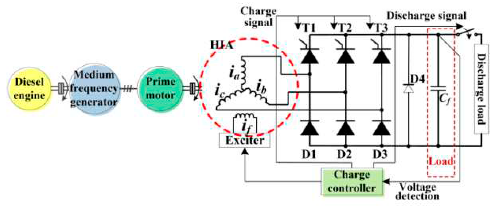
Figure 2.
The structure of HIA.
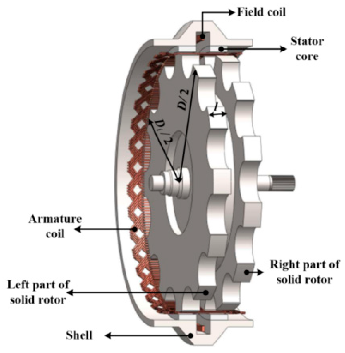
Figure 3.
The equivalent discharge-inductance model for HIA with rectifier and an extremely large capacitor.
Figure 3.
The equivalent discharge-inductance model for HIA with rectifier and an extremely large capacitor.
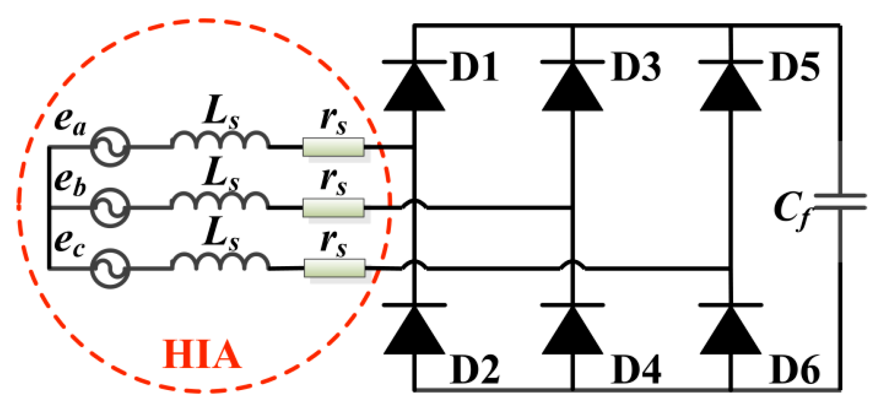
Figure 4.
Pictures of HIA rotor. (a) side view, (b) front view.
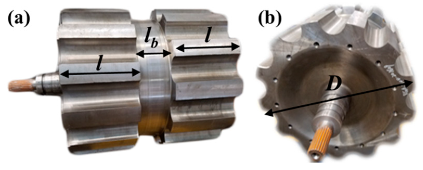
Figure 5.
The design flow of HTS HIA for CCPS.
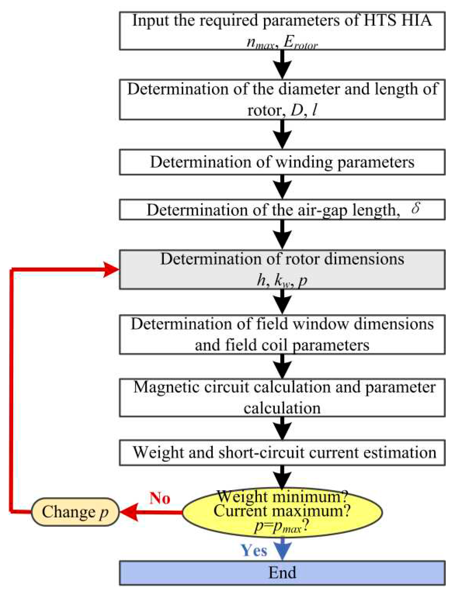
Figure 6.
The air-gap magnetic induction intensity distribution. (a)Two-dimensional distribution; (b) Along rotor position at different axial distance.
Figure 6.
The air-gap magnetic induction intensity distribution. (a)Two-dimensional distribution; (b) Along rotor position at different axial distance.

Figure 7.
The magnetic flux density distribution on rotor.
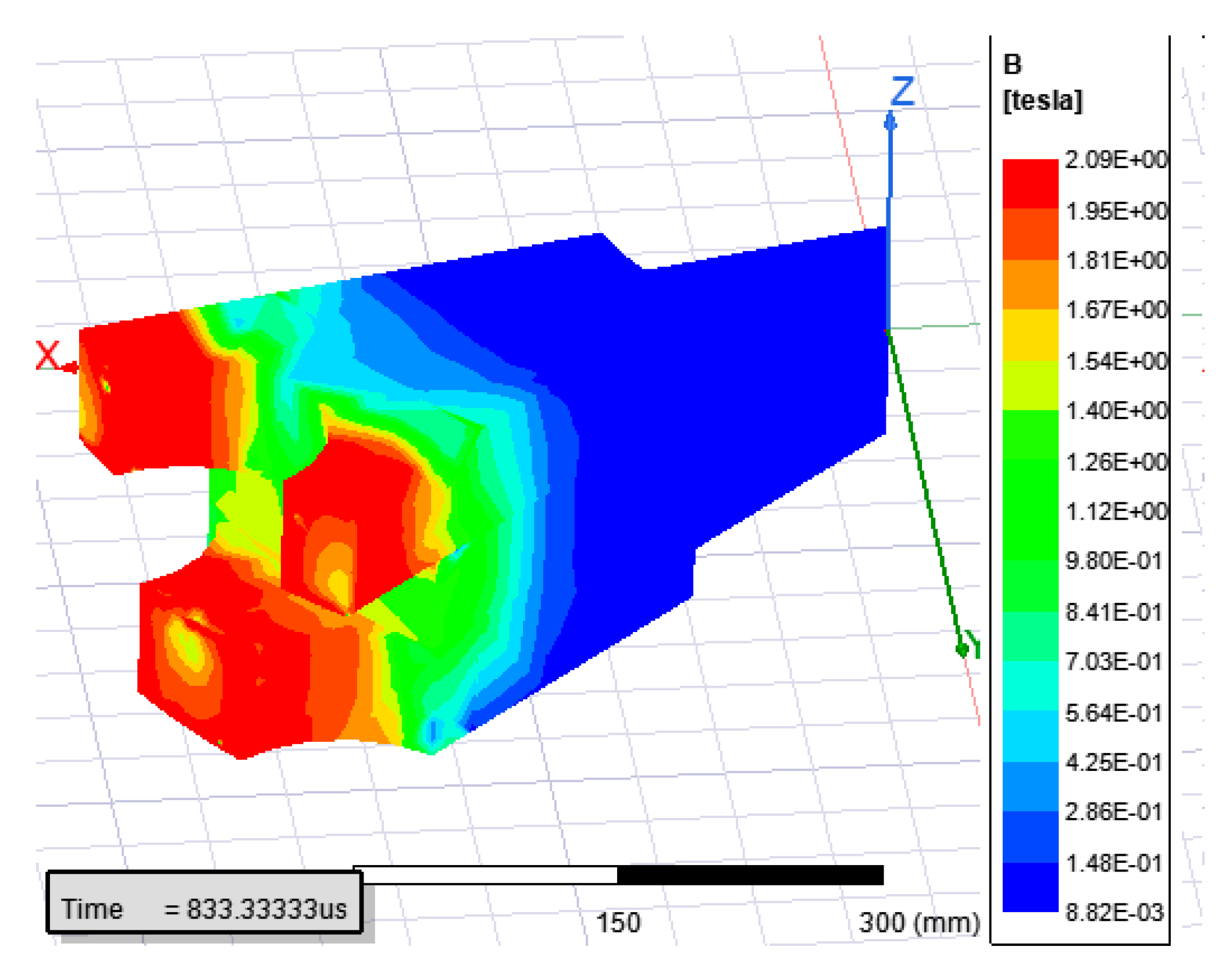
Figure 8.
The simulated waveforms of no-load induced EMF. (a) Phase EMF;(b) Line-to-line EMF.

Figure 9.
The simulated magnetic induction intensity distribution in the HTS field coil region.
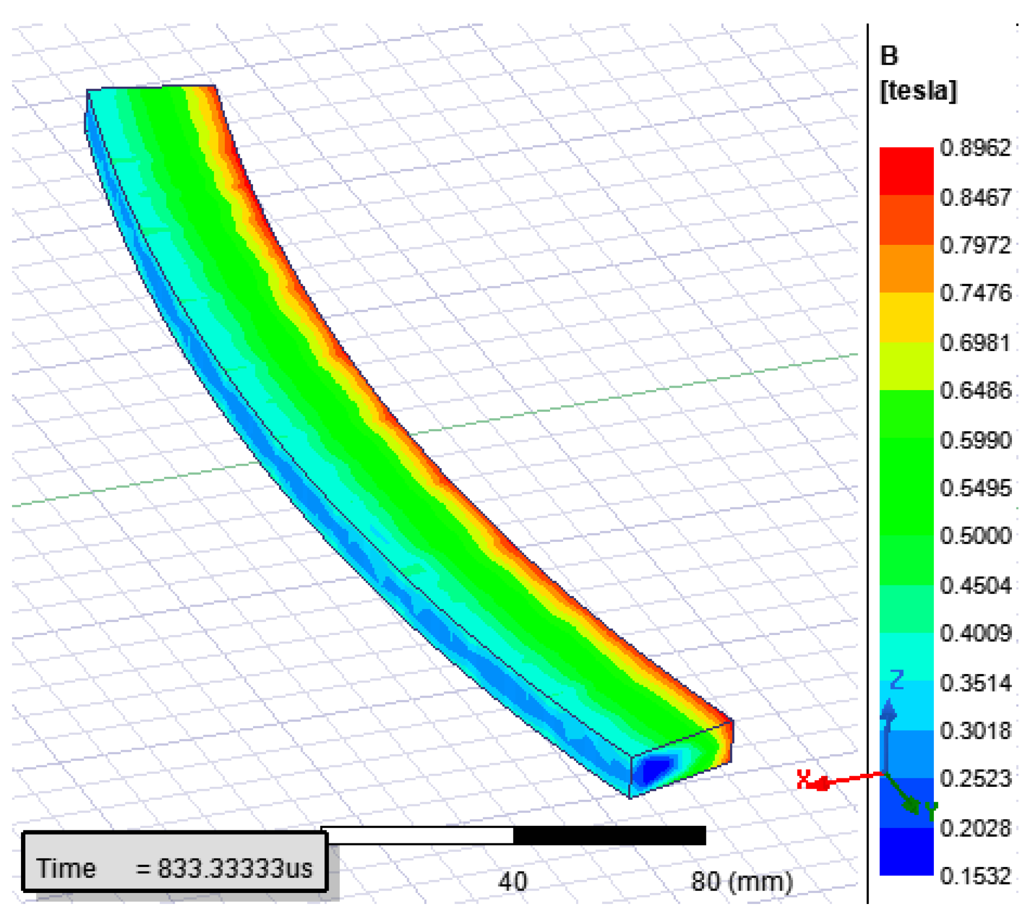
Figure 10.
(a) The Von Mises stress distribution of rotor (MPa);(b) The radial deformation of rotor (mm).
Figure 10.
(a) The Von Mises stress distribution of rotor (MPa);(b) The radial deformation of rotor (mm).
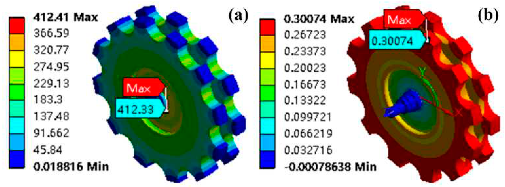
Figure 11.
The three-dimension models of two HIAs.
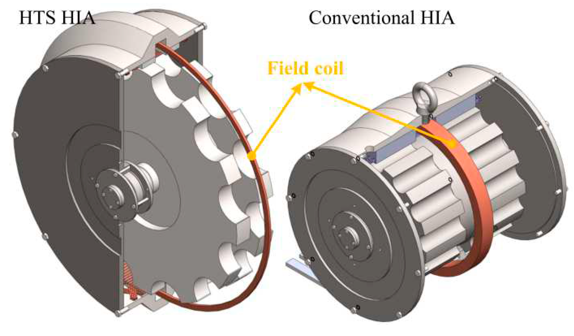
Figure 12.
The charge current and voltage waveforms. (a) The charge voltage;(b) The charge current.
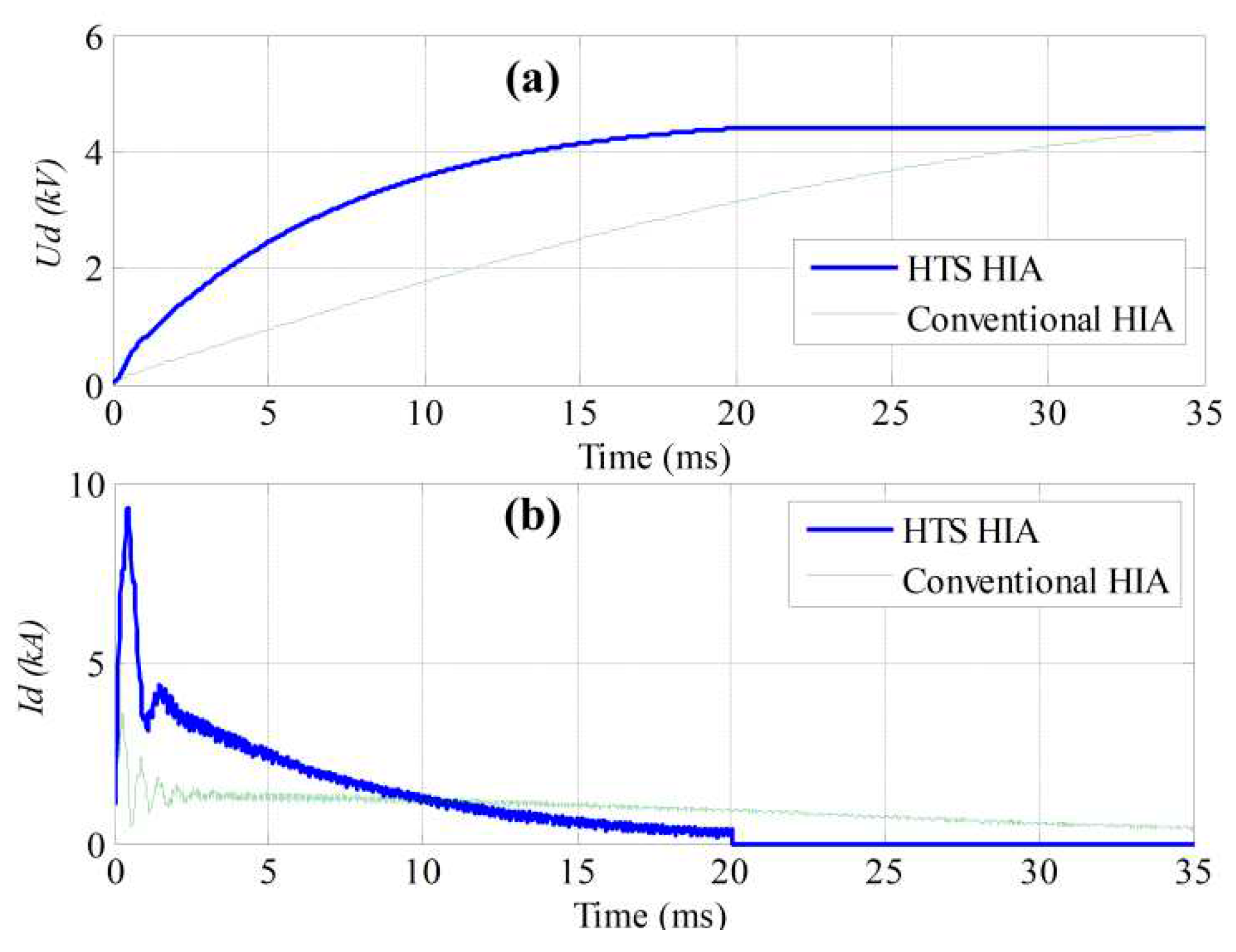
Figure 13.
The simulated rotor eddy-current losses waveforms. (b) is the close-up look of (a).
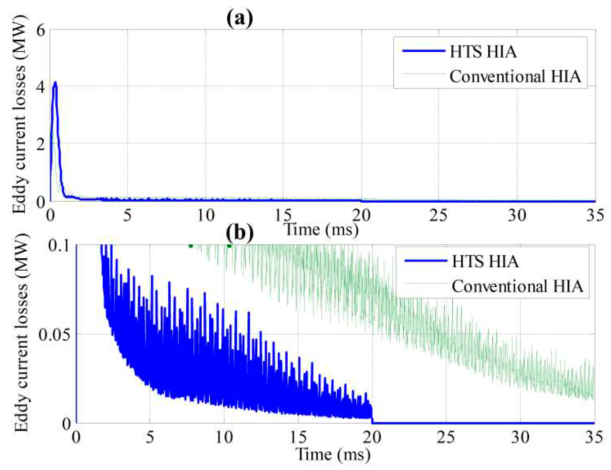

Table 1.
Parameters of conventional HIA.
| Symbol | Parameter | Value |
|---|---|---|
| D | Rotor diameter (mm) | 554 |
| p | Pole pair number | 13 |
| l | Length of rotor (mm) | 222 |
| δ | Air-gap length (mm) | 3 |
| Di | Stator-core inner diameter (mm) | 560 |
| Do | Stator-core outer diameter (mm) | 680 |
| z1 | Stator slot number | 78 |
| nr | Rotating speed (rpm) | 0-10000 |
Table 2.
Designed parameters of HTS HIA for CCPS.
| Symbol | Parameter | Value |
|---|---|---|
| D | Rotor diameter (mm) | 987 |
| p | Pole pair number | 12 |
| h | Rotor slot depth (mm) | 80 |
| l | Length of rotor (mm) | 70 |
| lb | Length of shaft or Exciting window width(mm) | 55 |
| δ | Air-gap length (mm) | 8 |
| Di | Stator-core inner diameter (mm) | 1003 |
| Do | Stator-core outer diameter (mm) | 1049 |
| z1 | Stator slot number | 288 |
| hf | Exciting window depth (mm) | 77 |
| Dh | Shell diameter (mm) | 1260 |
| a | Parallel branch number | 1 |
| q | Stator slot number per pole per phase | 4 |
| N | Number of series turns per phase | 48 |
| β | Short pitch coefficient of armature winding | 1 |
| nr | Rotating speed (rpm) | 0-6000 |
| Nf | Turn number of field coil | 60 |
| If | Rated field current (A) | 432 |
| lt | HTS tape length(m) | 200 |
| / | HTS tape conductor type | YBCO |
| TH | HTS tape operating temperature (K) | 40 |
| Ic | HTS tape critical current @40K and 0.9 T (A) | 600 |
| Wt | HTS tape width(mm) | 10 |
| Ht | HTS tape thickness(mm ) | 0.1 |
| / | Cryo-refrigerator weight(kg) | 160 |
| / | Cryo-refrigerator power(kW) | 7.5 |
Table 3.
Parameters of electromagnetic properties of HTS HIA for CCPS.
| Symbol | Parameter | Value |
|---|---|---|
| Erms | RMS value of no-load line-to-line induced EMF (V) | 4330 |
| Erotor | Energy storage of rotor (MJ) | 16 |
| Lds | Sub-transient inductance of d axis (mH) | 0.12 |
| Lqs | Sub-transient inductance of q axis (mH) | 0.132 |
| fmax | Maximum electrical frequency (Hz) | 1200 |
| Bδ | Maximum air-gap magnetic induction density at the middle position along axial direction (T) | 1.6 |
Table 4.
The comparison of two CCPSs.
| Parameters | Conventional HIA | HTS HIA |
|---|---|---|
| Maximum rotating speed nmax | 10000 | 6000 |
| Rotating speed at the end of last pulse (rpm) | 8000 | 4800 |
| RMS value of no-load induced line-to-line EMF (V)@ nmax and Ifn | 4800 | 4330 |
| Maximum electrical frequency (Hz) | 2166 | 1200 |
| Sub-transient reactance of d axis (Ω)@nmax | 2.72 | 0.91 |
| Sub-transient reactance of q axis (Ω)@nmax | 3.03 | 1.0 |
| Total weight of machine (kg) | 2200 | 1750 |
| Energy storage of rotor(MJ) | 15.7 | 16 |
| Charging time for last pulse (ms) | 35 | 20 |
| Charge efficiency for the last pulse | 79.4% | 86.1% |
| Average charge power for the last pulse(MW) | 2.14 | 3.75 |
Table 5.
Energy losses (J) for different kinds of losses for the last pulse.
| Conventional HIA | HTS HIA | |
|---|---|---|
| Armature winding copper losses | 10690 | 5600 |
| Stator iron core losses | 3630 | 780 |
| Rotor eddy-current losses | 3640 | 2570 |
| Copper losses of line | 900 | 2300 |
| Rectifier devices losses | 510 | 720 |
| Mechanical and windage losses | 230 | 250 |
| Total losses | 19600 | 12220 |
Disclaimer/Publisher’s Note: The statements, opinions and data contained in all publications are solely those of the individual author(s) and contributor(s) and not of MDPI and/or the editor(s). MDPI and/or the editor(s) disclaim responsibility for any injury to people or property resulting from any ideas, methods, instructions or products referred to in the content. |
© 2023 by the authors. Licensee MDPI, Basel, Switzerland. This article is an open access article distributed under the terms and conditions of the Creative Commons Attribution (CC BY) license (https://creativecommons.org/licenses/by/4.0/).
Copyright: This open access article is published under a Creative Commons CC BY 4.0 license, which permit the free download, distribution, and reuse, provided that the author and preprint are cited in any reuse.


