
Submitted:
24 June 2023
Posted:
25 June 2023
You are already at the latest version
Abstract
Peri-implant bone resorption has been reported around some implants after loading and this could create problems for the long-term stability of peri-implant soft and hard tissues. The causes are still not completely known, but a relevant importance could be assumed by the presence of a bacterial contamination at the micro-gap level of the implant-abutment junction. In this regard, external and internal implant-abutment assemblies have been shown to be much more permeable to bacterial colonization than Cone-Morse or conical connections. A subcrestal implant placement could have aesthetic advantages allowing a better prosthetic emergence profile. In literature controversial experimental and clinical results have been reported about bone resorption around implants placed equicrestally and subcrestally. Interestingly, Finite Element Analysis (FEA) studies revealed to be extremely useful for assessing the peri-implant bone strain and stress. Thus, the aim of this study was a FEA evaluation of implants with a Cone-Morse implant-abutment assembly (Implacil De Bortoli, São Paulo, Brazil) inserted into a bone block model (width: 10 mm, vertical height: 17.5 mm, thickness of the cortical area: 1.5 mm) mimicking equicrestal and subcrestal placements (1 and 2 mm). The results demonstrated that maximum stresses were observed within the cortical bone around the equicrestally placed implants, the lowest in the implant placed 2-mm subcrestally and intermediate stresses within the implant placed 1-mm subcrestally. Cortical bone was more stressed under lateral loads than axial loads. In conclusion, this FEA study suggested that implant placement at -1 mm could be recommended.
Keywords:
Bacterial leakage
; Cone-Morse connection
; dental implants
; equicrestal implant placement
; Finite Element Analysis (FEA)
; implant-abutment junction
; implant placement
; subcrestal implant placement.
1. Introduction
The peri-implant bone and soft tissues preservation over the long-term period is extremely important for the implant success rate [1]. However, in some cases, it is possible to observe a resorption of the bone, whose causes are not yet completely known, but they are probably related to a multitude of different factors, i.e. reformation of the biological width, presence of a bacterial infiltration at the implant-abutment micro-gap level, implant overloading, peri-implantitis, relative micromovements, peri-implant bone density, peri-implant soft tissue phenotype, surgical trauma during implant insertion, inter-implant distance, surface structure, and implant neck or abutment characteristics and macro-design [2,3,4,5,6,7,8,9,10]. A relevant role is certainly held by the presence of a bacterial reservoir at the level of the voids present in the implant-abutment junction (IAJ) after the insertion of the abutment into the implant [11,12,13]. In any case, in literature it is known that not all implant-abutment connections behave in a similar way. For example, external and internal implant-abutment assemblies have been shown to be much more permeable to bacterial colonization than Cone-Morse or conical connection assemblies [14]. In fact, the conical contact between the implant and the abutment has been demonstrated to allow a better distribution of masticatory forces and a reduction of mechanical stress on the surrounding bone. This is especially important to promote bone health and prevent its resorption.
The crestal and subcrestal placement of dental implants, instead, refers to the depth at which the implant is inserted into the bone tissue of the jaw. Crestal positioning is the most common technique, in which the implant is inserted in the site of tooth extraction or in a previously edentulous area, until it reaches the level of the alveolar bone margin. In this way, the neck of the implant is at the same level of the gum or just below it. This technique is commonly used when the level of the alveolar bone is adequate to ensure a good primary stability of the implant and a correct aesthetics to the final result. On the other hand, subcrestal implant placement involves inserting the implant so that the implant neck is positioned below the level of the alveolar bone margin. This can be done when the quantity of the alveolar bone is insufficient in height or thickness [7,8,9]. The goal is to cover the implant neck with the gum tissue, creating a "shield" effect that can contribute to the long-term stability of the implant and the preservation of gingival aesthetics. Both methods present some advantages and disadvantages. The crestal positioning could offer a greater surgical ease and a better accessibility for cleaning or maintenance of the implant. However, it may require an adequate volume of alveolar bone to achieve a sufficient primary stability. Subcrestal implant placement could be useful in cases of reduced bone volume or in order to improve gingival aesthetics, but the surgical procedure may become more intricate and necessitate heightened focus on gum management during the healing process [7,10]. The choice on the implant positioning will depend on various factors, including the patient's anatomical features, the desired aesthetics, bone stability, and implant surgeon preferences. Inserting an external or internal connection below the alveolar crest would mean to apically move the micro-gap colonized by bacteria with a possible resultant higher resorption rate [14]. On the contrary, those connections that are more resistant to the bacterial leakage, e.g. Cone-Morse and conical ones, could be positioned more apically in relation to the alveolar crest with a very small or no peri-implant bone resorption [15,16,17]. Thus, the subcrestal positioning of a Cone-Morse connection could be possible from biological and clinical points of view [15,16,17]. This practice could carry significant beneficial implications, mainly from an aesthetic point of view, because it would allow a better prosthetic emergence profile. However, different and controversial results have been reported in literature by in vitro, animal, and clinical studies, as well as systematic reviews of the literature, about different resorption rates related to implants inserted in equicrestal or subcrestal positions [18,19,20,21,22,23,24,25,26,27,28,29,30,31,32,33,34].
In the last few years, Finite Element Analysis (FEA) studies demonstrated to be extremely useful in evaluating several different aspects of the biomechanical characteristics of dental implants and bone [35,36]. FEA analysis is a computational simulation technique that uses numerical methods to model and analyze the behavior of an object or structure under load. In case of dental implants, a FEA model can be created to represent the implant, the surrounding bone, and the gum tissue. The model can be used to simulate loading conditions to which the implant is subjected during chewing and to evaluate the stress and deformation factors generated into the bone and within the implant itself. The Finite Element Method (FEM) can be also used to study the behavior of dental implants basing on the depth of dental insertion into the bone tissue and is able to provide information about how the load distribution between the implant and the surrounding bone at different insertion depths. This may help identifying areas of increased strain or overload that could affect the stability and durability of the system [37,38,39,40,41,42]. Furthermore, FEA studies could help assessing how the insertion depth affects the implant primary stability, thereby identifying the ideal depth for achieving the optimal implant anchorage in bone tissue, since primary stability is considered a critical factor for successful bone integration. In this context, the FEA could also estimate the surrounding bone response to the implant insertion at different depths. This may provide simulated indications of possible bone resorption or increase in bone density, which may occur over time due to the interaction between implant and bone [42,43,44].
All this information is important to ensure that both implant and bone would be not subjected to excessive stresses that could lead to implant failure or complications. It is important to note that FEA is a numerical simulation tool, and its predictions depend on the accuracy of data and material properties used in the model. Therefore, FEA studies should be considered as a support for the interpretation of the results and further clinical decisions should be made basing on an overall assessment, also taking into account other patient-specific clinical and radiographic considerations [35,36,37,38,39,40,41,42,43,44].
For that reason, this study has been conducted to perform a FEA survey of implants presenting a Cone-Morse implant-abutment assembly, inserted in different positions relative to the alveolar crest.
2. Materials and Methods
2.1. Modelling
A cross-section of a bone block with a width of 10 mm and a vertical height of 17.5 mm was designed with a computer-aided design (CAD) software (Autodesk Inventor, San Francisco, CA, USA) based on a computed tomography (CT) scan of a patient. The cortical area resulted to be 1.5 mm in thickness (Figure 1a). The implant model used has a diameter of 4 mm and a length of 9 mm, while the abutment has a length of 8.3 mm and the same diameter (Implacil De Bortoli, São Paulo, Brazil). In Figure 1b, it is possible to observe the drawing view and the dissected view, in which the Cone-Morse connection between implant and abutment is represented.
The implant model has been equicrestally placed in the bone block so that the implant shoulder was at the same level of the crest. On the contrary, subcrestal patterns have been generated by the placement of the implant model at 1 mm and 2 mm below the crestal level, respectively (Figure 2). The software used to perform these placements was Ansys Workbench (Canonsburg, PA, USA).
It is a common practice to consider both cortical and trabecular bones as isotropic materials when utilizing a FEA study model to examine the behavior of bones in relation to dental implants. This would mean that the mechanical properties of the bone have been assumed to be uniform and not influenced by a specific direction [1]. The cortical bone is the outermost and most compact region of the bone, forming a protective layer around the inner trabecular bone. The trabecular bone, instead, also known as spongy bone or cancellous bone, is a porous framework composed of bony trabeculae creating a three-dimensional network [2]. In the context of a FEA model, cortical bone is represented as a more rigid and strong material, while trabecular bone is considered more flexible and less resistant. This difference in mechanical properties reflects the physical characteristics of the bone itself. When developing a FEA model to simulate cortical and trabecular bone, specific values of Young's modulus (stiffness measurement) and Poisson's modulus (deformability measurement) can be assigned to both bone types. However, it is important to note that parameter values can greatly vary depending on the anatomical location and individual variabilities. It is possible to acquire the mechanical properties related to cortical and trabecular bones from biomechanical studies, experimental data, or scientific literature. Typical Young's modulus values for cortical bone can range from 13 to 20 GPa, while for trabecular bone they can range from 0.1 to 4 GPa. Conversely, Poisson's modulus for both types of bone can be considered around 0.3 [1,2,3]. Representing cortical and trabecular bone as isotropic materials could allow to simplify modelling and analysis within FEA study, but it is important to emphasize the complex biological nature of the bone and that its structure and mechanical properties could vary even within the same individual.
The dimensions and properties assigned to the models related to the cortical bone, the trabecular bone, and the titanium implant used in this study were reported in Table 1.
2.2. Loads
Among the most important finite element parameters, besides bone properties, there can be found loading and boundary conditions. In this study limiting conditions have been established, corresponding to the mesial and distal surfaces of the bone model. Then, boundary contact conditions between implant and trabecular bone were fixed simulating an ideal osseointegration. The simulated load has been applied on the upper surface of the abutment with an oblique force of 200 N of magnitude and with an inclination of 45° in respect to the longitudinal axis of the implant (Figure 3).
2.3. Finite Element Method (FEM)
The accuracy of results resulted to be strongly dependent on the convergence testing process and the mesh quality [5,6,35], thus the mesh element size chosen for this research was established at 0.5 mm of tetrahedral elements in the part of the screw and bone. Contrarily, on the lower surface of the abutment, a mesh refinement was performed in order to achieve a more accurate distribution of Von Mises stress. This area is considered critical when the implant is subjected to inclined loads, as supported by existing literature [37]. Mesh refinement can be useful in solving problems that require more precise details of the model or involve high stress gradients, such as analyzing complex structural components or simulating fluid flows. However, it is important to note that excessive mesh refinement can lead to longer computation times and increased complexity in managing the results. Therefore, it is essential to balance the mesh refinement based on the problem specifications and available computational resources to obtain reliable and efficient results. In this case, a mesh refinement was applied, resulting in a reduction of the element size to 0.3 mm in the abutment portion. (Figure 4).
The friction generated between the abutment and the dental implant is an important factor to consider when designing and installing a dental implant. Indeed, the final goal is obtaining adequate stability and tightness between the abutment and the implant, in order to guarantee the absence of micromovements at the implant-abutment connection zone and a long-term implant stability. An appropriate level of friction between the abutment and the implant is desirable to avoid those micro-movements that could compromise the integrity of the interface, prevent the loss of the prosthetic material and the abutment mobility, as well as reduce the risk of bacterial infiltration by creating a good bacterial seal. A frictional coefficient of 0.3 was set as the implant-abutment contact condition in the present FEA study (Figure 5).
The software used for the FEA simulation was Ansys Workbench (Canonsburg, PA, USA).
3. Results
Data concerning mathematical solutions have been converted into visual results as color gradients from red to blue. The blue color indicated the minimum stress, whereas the red one the maximum stress. All the shades present in this range were considered as the stress variation. Then, stress values were measured at different points collected from the studied models, and then compared. Von Mises equivalent stress levels were used to identify points with the greatest stress for both dental implants and bone [44]. Figure 6 showed results of Von Mises stresses on both cortical and trabecular bones and on implants.
Von Mises stresses displayed in Figure 6 at various depths of implant positioning showed how the stress resulted higher in case of implant positioning at the same level of the bone (equicrestally). In addition, it was detected higher stresses in the cortical bone than in the trabecular bone due to the different stiffness of materials. In particular, in the equicrestal positioning it can be observed how the first four fillets of the thread recorded stresses ranging between 80 and 170 Mpa, while the latest fillets recorded stress values ranged from 3 Mpa to 30 Mpa.
In the apical area of the implant, it can be observed how the equicrestal positioning induced a compressive stress on the surrounding bone, reaching a stress level of approximately 50 MPa. However, this value did not compromise the strength of the trabecular bone, as the compressive strength of the trabecular bone relies on both its density and unique structure, and it is precisely this structure that gives it a greater resilience than the cortical bone that is more compact. On the other hand, the maximum trabecular bone stresses were registered close to the implant head, and they linearly decreased with the decrease of bone depth. Indeed, stresses on the cortical and trabecular bones increased when the thickness of the cortical bone decreased.
The applied oblique loading caused higher Von Mises stress values on both cortical and trabecular bones. After the evaluation of stresses in the bone around the equicrestally, and -1 mm and -2 mm subcrestally placed implants, it could be observed three different situations: the highest stress could be recorded within the cortical bone around the equicrestally inserted implant, the intermediate stress around the subcrestal implant placed at -1 mm, and the lowest one was detected in the subcrestal implant placed at -2 mm (Figure 6 and Figure 7).
From Figure 7 it can be noticed that as soon as implants further penetrated the jaw, stresses in the cortical bone decreased, whereas stresses in the trabecular bone increased. The maximum stresses found in the cortical bone decreased from 60 to 20 MPa, while in the trabecular bone, the region experiencing stresses greater than 8 Mpa expanded up to three threads of the implant screw. However, from the results it could be possible to notice how under eccentric load the subcrestal implant positioning was able to transfer a compression stress from the cortical bone to the trabecular bone in a more uniform manner.
4. Discussion
As it has been already reported in literature, the insertion of an implant platform in a more apical position relatively to the alveolar crest could give better aesthetic results [15,16]. However, only implants that presented a very low percentage of bacteria at the IAJ level could be safely inserted in a subcrestal position [45,46,47,48,49]. Different experimental, clinical, and radiological results have been reported when Cone-Morse implants were inserted in a subcrestal position, but a consensus on this topic has been never reached [20,22,27,29,30,34]. In animal experiments and in human histological studies on retrieved Cone-Morse implants, it was found that no resorption or a smaller amount of resorption of the peri-implant bone was present, and also that, in some specimens, newly formed bone tended to overgrow the implant shoulder and the micro-gap, touching the abutment surface [15,16,23,32,45,46,47,48]. Overall, a systematic review with meta-analysis reported that in most of the evaluated papers no differences were found in peri-crestal bone levels of equicrestally and subcrestally situated implants [26]. In addition, clinical reports as well corroborated these data with similar results [24,25]. Other FEA studies have also found a significantly greater strain peak in external hexagon connections when compared to Cone-Morse connections [41,42]. Moreover, it was also reported that peak stresses were moved away from the crestal peri-implant bone to subcrestally positioned implants [9,18].
The cortical bone is responsible for transmitting occlusal loads to the implant bone interface, due to its high stiffness compared to the trabecular bone. For this reason, implants inserted in a subcrestal position that do not have contact with the cortical bone exhibit distinct mechanical characteristics compared to those placed in a more crestal position. It has been observed that the maximum compression stress value on the bone provides useful information to analyze bone resorption with respect to the tension stress value [12]. In particular, Salles Sotto-Maior et al. [21] provided evidence of bone resorption resulting from stress overload when compression stress exceeds the range of 80-130 MPa on the cortical bone. In contrast, the present study found that an equicrestal implant positioning, coupled with the application of an oblique load, resulted in a stress level of 60 MPa on the cortical bone. However, when using subcrestal placements, significantly lower and safer stress values of 20 and 15 MPa were observed. Consequently, this reduction in stress can be attributed to the placement of the implant at a depth of approximately 1.5 mm, leading to the growth of coronal bone at the interface and contributing to an increased success rate. In the present FEA study, it was observed that as the depth of implant placement increased, there was a corresponding rise in compressive stress on the apical region of the implant, as shown in Figure 7. This occurrence can be attributed to the displacement of the fulcrum of force towards the apical region, resulting in a greater lever arm. This displacement is caused by the increased interaction between the implant and trabecular bone, leading to the observed phenomenon. In addition, the reduced section of the apical area of the implant decreased the contact area available to dissipate stress with the bone, and therefore there is an increase in stress. These observations provide a potential explanation for the critical significance of the system design, particularly in the apical area, when choosing the subcrestal implant positioning.
To ensure the appropriate implant placement, it is crucial to carefully assess occlusal loads. Therefore, conducting these evaluations prior to any occlusal adjustments is imperative in order to mitigate the risk of bone resorption resulting from elevated stress levels. In both 1-mm and 2-mm subcrestal models, a reduction in stress was observed in the cortical area. This finding suggests that, in scenarios where patients are subjected to occlusal loads, such as parafunctions, a subcrestal positioning would be more advantageous compared to an equicrestal positioning. This analysis allowed to understand the factors to be taken into account when choosing the depth of insertion of the implant. It is important to highlight that subcrestal placement stresses a significant portion of the trabecular bone, aligning with the findings of Rismanchian et al. [50]. This supports the notion that appropriately stimulated bone can undergo reshaping along the implant surface. The FEM analysis helped these researchers understanding that when implant positioning occurred subcrestally at about 1 mm, the transfer of load was more beneficial for bone growth when compared to cases where the insertion depth was greater. The reason can be linked to the fact that in this latter scenario, a higher amount of tension was absorbed, resulting in a notable reduction of tension within the trabecular bone, which did not favor new bone formation.
FEM analysis is a powerful simulation tool that allows you to evaluate structural behavior and stresses in a variety of situations [51]. However, like any modelling and simulation tool, there are some limitations that are important to consider when using FEA to assess stress variations. Among them, we find the accuracy of the input data. In fact, the accuracy of FEM analysis results depends on the quality of the input data used, such as loading conditions and material properties. With respect to this last point, all materials were considered homogeneous, isotropic, and linearly elastic, although the mandibular cortical bone was crosswise isotropic and inhomogeneous. Alternatively, considering the materials as anisotropic, and so with mechanical properties that vary in different directions, would require the use of more sophisticated and complex FEA models and the consideration of additional parameters to describe and determine the mechanical behavior of the material. Therefore, simplifying a material as isotropic can be an approximation and may not fully reflect the actual behavior of the material. In general, the choice to consider a material as isotropic or anisotropic depends on the specific characteristics of the material and application, as well as the objective of the FEA analysis. It is important to carefully consider which approach is most appropriate to obtain accurate and representative results. However, it also holds significance to take into account the morphology, density, and concentration of the trabeculae, in order to determine their influence on the results obtained from FEA simulations. In addition, simplifications have also been made with regard to geometry. These simplifications may affect the final results and may not consider all the real interactions between components. Despite this, for the purpose of simplification, these properties were disregarded in the modeling of this study.
Other two identified factors that influenced the simulation were the material used for the implant and the surface roughness. The optimal properties of the implant material allow to increase the bone regeneration process and so, the early stabilization of the implant [51,52]. Instead, the increased roughness of the surface in turn increased the coefficient of friction between the surface of the material [53]. In this FEA study, details of the implant surface roughness have been ignored since the study aim focused only on the effect of tensions within the bone.
Although FEA studies have been previously employed to anticipate the biomechanical performance of different implant designs and examine the impact of clinical factors on the success of implants, there is still a need to comprehensively assess and understand the correlation between numerous variables for long-term implant success, aiming to enhance clinical results. These variables encompass refining the simulation process with realistic properties of materials and their geometry, accounting for variations of the bone porosity, considering design parameters, implant surface roughness, different analysis techniques, variations in insertion conditions, and the possibility to incorporate cyclic loads that may induce implant fatigue.
This research has been essential in refuting the null hypothesis stated in the Introduction section, as it has demonstrated the crucial role of implant positioning and bone crest thickness in influencing the osseointegration process [54].
5. Conclusions
In this study, higher stresses were recorded in the cortical bone. However, this should not represent a risk element as it has been expected, because the cortical bone had a higher modulus of elasticity than the trabecular bone (Table 1). Observing data reported in literature on compressor resistance values (140 MPa for the cortical bone and 10 MPa for the trabecular bone) [55,56], it can be concluded that a subcrestally insertion of the implant at 2 mm below the crestal level generated stresses on the trabecular bone with a value of 13 MPa. This would mean that the trabecular bone was overstressed with the risk of bone absorption. However, a complete insertion of the implant into the trabecular bone, could lead to complications due to the higher generated stresses. Another factor to keep in mind is the apical area of the implant which, as we have seen, increases the trabecular bone with compression and this increase has a plateau at about 1.5 mm and then increases with the depth of insertion of the implant.
Apart from the limitations of the present FEA study, the following conclusions can be drawn:
- The values of maximum Von Mises stress in the cortical bone near the implant switching platform decreased when the implant was placed in subcrestal positions compared to the equicrestal position;
- The cortical bone experienced higher stress levels under lateral loads compared to axial loads;
- Subcrestal implant positioning at -1 mm could be a highly recommended approach.
To conclude, from the results obtained from the subcrestally positioned implants, it could be observed that a reduction in bone stress and strain in the surrounding area could be observed only at specific insertion depths: -1 mm or -2 mm. Thus, implant positioning at 1.5 mm may be recommended to obtain an adequate stress distribution pattern.
Overall, it is important to consider the limitations of this FEA study described earlier and use these results to lay the groundwork for establishing correlations with clinical data, thereby offering valuable insights into the biomechanical properties of implants prior to their in vivo placement.
Author Contributions
Conceptualization, A.P. and B.T.; methodology, M.C., T.R. and M.T.; software, M.C.; validation, M.C. and A.S.; formal analysis, T.R. and A.S..; investigation, M.C.; resources, N.D.B.J. and B.F.M.; data curation, M.C., T.R. and N.D.P.; writing—original draft preparation, N.D.P., M.C. and T.R.; writing—review and editing, N.D.P., B.T. and A.P.; visualization, A.S., N.D.B.J. and B.F.M.; supervision, B.T.; project administration, A.P. and B.T. All authors have read and agreed to the published version of the manuscript.
Funding
This research received no external funding.
Data Availability Statement
Data are contained within the article and available on request from the corresponding author.
Acknowledgments
The authors gratefully thank the Implacil De Bortoli Company, São Paulo, Brazil, for all the mathematical information regarding implants.
Conflicts of Interest
The authors declare no conflict of interest.
References
- Kohen, J.; Matalon, S.; Block, J.; Ormianer Z. Effect of implant insertion and loading protocol on long-term stability and crestal bone loss: A comparative study. J Prosthet Dent 2016, 6, 697-702. [CrossRef]
- Duyck, J.; Naert, I.E.; Van Oosterwyck, H.; Van der Sloten, J.; De Cooman, M.; Lievens, S; Puers, B. Biomechanics of oral implants: A review of the literature. Technol Health Care 1997, 4, 253-73.
- Duyck, J.; Rønold, H.; Van Oosterwyck, H.; Naert, I.; Vander Sloten, J.; Ellingsenet, J.E. The influence of static and dynamic loading on marginal bone reactions around osseointegrated implants: An animal experimental study. Clin Oral Implants Res 2001, 3, 207-18. [CrossRef]
- Tarnow, D.P.; Cho, S.C.; Wallace, S.S. The effect of inter-implant distance on the height of inter-implant bone crest. J Periodontol 2000, 4, 546-9. [CrossRef]
- Misch, C.E.; Suzuki, J.B.; Misch-Dietsh, F.M.; Bidez, M.V. A positive correlation between occlusal trauma and peri-implant bone loss: Literature support. Implant Dent 2005, 2, 108-16. [CrossRef]
- Kheiralla, L.S.; Younis, J.F. Peri-implant biomechanical responses to standard, short-wide, and mini-implants supporting single crowns under axial and off-axial loading (an in vitro study). J Oral Implantol 2014, 1, 42-52. [CrossRef]
- Valles, C.; Rodriguez-Ciurana, X.; Muñoz, F.; Permuy, M.; López-Alonso, H.; Nart, J. Influence of implant neck surface and placement depth on crestal bone changes and soft tissue dimensions around platform-switched implants: A histologic study in dogs J Clin Periodontol 2018, 7, 869-883. [CrossRef]
- Chu, C.M.; Huang, H.L.; Hsu, J.T.; Fuh, L.J. Biomechanical evaluation of subcrestal placement of dental implants: in vitro and numerical analyses. J Periodontol 2011, 2, 302-10. [CrossRef]
- Cruz, R.S.; Lemos, C.A.A.; de Luna Gomes, J.M.; Fernandes, E.; Oliveira, H.F.; Pellizzer, E.P.; Verri, F.R. Clinical comparison between crestal and subcrestal dental implants: a systematic review and meta-analysis. J Prosthet Dent 2022, 3, 408-417. [CrossRef]
- Barros, R.R.; Novaes, A.B. Jr; Muglia, V.A.; Iezzi, G.; Piattelli, A. Influence of interimplant distances and placement depth on peri-implant bone remodeling of adjacent and immediately loaded Morse cone connection implants: a histomorphometric study in dogs. Clin Oral Implants Res 2010, 4, 371-8. [CrossRef]
- Assenza, B.; Tripodi, D.; Scarano, A.; Perrotti, V.; Piattelli, A.; Iezzi, G.; D’Ercole, S. Bacterial leakage in implants with different implant-abutment connections: an in vitro study. J Periodontol 2012, 4, 491-7. [CrossRef]
- D'Ercole, S.; Tripodi, D.; Marzo, G.; Bernardi, S.; Continenza, M.A.; Piattelli, A.; Iaculli, F.; Mummolo, S. Microleakage of bacteria in different implant-abutment assemblies: an in vitro study. J Appl Biomater Funct Mater 2015, 2, 174-80. [CrossRef]
- Tripodi, D.; D'Ercole, S.; Iaculli, F.; Piattelli, A.; Perrotti, V.; Iezzi, G. Degree of bacterial microleakage at the implant-abutment junction in Cone Morse tapered implants under loaded and unloaded conditions. J Appl Biomater Funct Mater 2015, 4, 367-71. [CrossRef]
- Castro, D.S.; Araujo, M.A.; Benfatti, C.A.; dos Reis Pereira de Araujo, C.; Piattelli, A.; Perrotti, V.; Iezzi, G. Comparative histological and histomorphometrical evaluation of marginal bone resorption around external hexagon and Morse cone implants: an experimental study in dogs. Implant Dent 2014, 3, 270-6. [CrossRef]
- Degidi, M.; Iezzi, G.; Scarano, A.; Piattelli, A. Immediately loaded titanium implant with a tissue-stabilizing/maintaining design ('beyond platform switch') retrieved from man after 4 weeks: a histological and histomorphometrical evaluation. A case report. Clin Oral Implants Res 2008, 3, 276-82. [CrossRef]
- Degidi, M.; Perrotti, V.; Shibli, J.A.; Novaes, A.B.; Piattelli, A.; Iezzi, G. Equicrestal and subcrestal dental implants: a histologic and histomorphometric evaluation of nine retrieved human implants. J Periodontol 2011, 5, 708-15. [CrossRef]
- Degidi, M.; Nardi, D.; Daprile, G.; Piattelli, A. Nonremoval of immediate abutments in cases involving subcrestally placed post-extractive tapered single implants: a randomized controlled clinical study. Clin Implant Dent Relat Res 2014, 6, 794-805. [CrossRef]
- Chu, C.M.; Huang, H.L.; Hsu, J.T.; Fuh, L.J. Influences of internal tapered abutment designs on bone stresses around a dental implant: three-dimensional finite element method with statistical evaluation. J Periodontol 2012, 1, 111-8. [CrossRef]
- Ferraro-Bezerra, M.; Rodrigues Carvalho, F.S.; Nogueira Cunto, G.M.; Duarte Carneiro, B.G.; de Barros Silva, P.G. Does subcrestal position affect insertion torque of different implant designs at different bone densities? An In Vitro Model Study. Int J Oral Maxillofac Implants 2021, 3, 460-467. [CrossRef]
- Valles, C.; Rodríguez-Ciurana, X.; Clementini, M.; Baglivo, M.; Paniagua, B.; Nart, J. Influence of subcrestal implant placement compared with equicrestal position on the peri-implant hard and soft tissues around platform-switched implants: a systematic review and meta-analysis. Clin Oral Investig 2018, 2, 555-570. [CrossRef]
- Salles Sotto-Maior, B.; de Andrade Lima, C.; Mendes Senna, P.; de Villa Camargos, G.; Del Bel Cury, A.A. Biomechanical evaluation of subcrestal dental implants with different bone anchorages. Braz Oral Res 2014, 28, S1806-83242014000100235. [CrossRef]
- Saleh, M.H.A.; Ravidà, A.; Suárez-López Del Amo, F.; Lin, G.H.; Asa'ad, F.; Wang, H.L. The effect of implant-abutment junction position on crestal bone loss: a systematic review and meta-analysis. Clin Implant Dent Relat Res 2018, 4, 617-633. [CrossRef]
- Todescan, F.F.; Pustiglioni, F.E.; Imbronito, A.V.; Albrektsson, T.; Gioso, M. Influence of the microgap in the peri-implant hard and soft tissues: a histomorphometric study in dogs. Int J Oral Maxillofac Implants 2002, 4, 467-72.
- Nagarajan, B.; Murthy, V.; Livingstone, D.; Surendra, M.P.; Jayaraman, S. Evaluation of crestal bone loss around implants placed at equicrestal and subcrestal levels before loading: a prospective clinical study. J Clin Diagn Res 2015, 12, ZC47-50. [CrossRef]
- Sargolzaie, N.; Zarch, H.H.; Arab, H.; Koohestani, T.; Ramandi, M.F. Marginal bone loss around crestal or subcrestal dental implants: prospective clinical study. J Korean Assoc Oral Maxillofac Surg 2022, 3, 159-166. [CrossRef]
- Palacios-Garzón, N.; Velasco-Ortega, E.; López-López, J. Bone loss in implants placed at subcrestal and crestal level: a systematic review and meta-analysis. Materials (Basel) 2019, 1, 154. [CrossRef]
- Palacios-Garzón, N.; Mauri-Obradors, E.; Ayuso-Montero, R.; Velasco-Ortega, E.; Anglada-Cantarell, J.M.; López-López, J. Marginal bone loss in internal conical connection implants placed at the crestal and subcrestal levels before prosthetic loading: a randomized clinical study. Materials (Basel) 2022, 10, 3729. [CrossRef]
- Pessoa, R.S.; Sousa, R.M.; Pereira, L.M.; Neves, F.D.; Bezerra, F.J.; Jaecques, S.V.; Sloten, J.V.; Quirynen, M.; Teughels, W.; Spin-Neto, R. Bone remodeling around implants with External Hexagon and Morse-Taper connections: a randomized, controlled, split-mouth, clinical trial. Clin Implant Dent Relat Res 2017, 1, 97-110. [CrossRef]
- Gatti, C.; Gatti, F.; Silvestri, M.; Mintrone, F.; Rossi, R.; Tridondani, G.; Piacentini, G.; Borrelli, P. A prospective multicenter study on radiographic crestal bone changes around dental implants placed at crestal or subcrestal level: one-year findings. Int J Oral Maxillofac Implants 2018, 4, 913-918. [CrossRef]
- Ercoli, C.; Jammal, G.; Buyers, M.; Tsigarida, A.A.; Chochlidakis, K.M.; Feng, C.; Caton, J. Influence of apico-coronal implant placement on post-surgical crestal bone loss in humans. J Periodontol 2017, 8, 762-770. [CrossRef]
- Chatterjee, P.; Shashikala, R.; Navneetham, A. comparative study of the crestal vs subcrestal placement of dental implants via radiographic and clinical evaluation. J Contemp Dent Pract 2022, 6, 623-627.
- Fetner, M.; Fetner, A.; Koutouzis, T.; Clozza, E.; Tovar, N.; Sarendranath, A.; Coelho, P.G.; Neiva, K.; Janal, M.N.; Neiva, R. The effects of subcrestal implant placement on crestal bone levels and bone-to-abutment contact: a microcomputed tomographic and histologic study in dogs. Int J Oral Maxillofac Implants 2015, 5, 1068-75. [CrossRef]
- Huang, B.; Meng, H.; Zhu, W.; Witek, L.; Tovar, N.; Coelho, P.G. Influence of placement depth on bone remodeling around tapered internal connection implants: a histologic study in dogs. Clin Oral Implants Res 2015, 8, 942-949. [CrossRef]
- Jain, S.; Mattoo, K.; Khalid, I.; Baig, F.A.H.; Kota, M.Z.; Ishfaq, M.; Ibrahim, M.; Hassan, S. A study of 42 partially edentulous patients with single-crown restorations and implants to compare bone loss between crestal and subcrestal endosseous implant placement. Med Sci Monit 2023, 29, 939225. [CrossRef]
- Kang, N.; Wu, Y.Y.; Gong, P.; Yue, L.; Ou, G.M. A study of force distribution of loading stresses on implant-bone interface on short implant length using 3-dimensional finite element analysis. Oral Surg Oral Med Oral Pathol Oral Radiol 2014, 5, 519-23. [CrossRef]
- Ellendula, Y.; Sekar, A.C.; Nalla, S.; Basany, R.B.; Sailasri, K.; Thandu, A. Biomechanical evaluation of stress distribution in equicrestal and sub-crestally placed, platform-switched Morse taper dental implants in D3 bone: Finite Element Analysis. Cureus 2022, 4, 24591. [CrossRef]
- Sesha, M.R.; Sunduram, T.; Eid Abdelmagyd, H.A. Biomechanical evaluation of stress distribution in subcrestal placed platform-switched short dental implants in D4 bone: in vitro Finite Element Model study. J Pharm Bioallied Sci 2020, 12, S134-S139. [CrossRef]
- Santonocito, D.; Nicita, F.; Risitano, G. A parametric study on a dental implant geometry influence on bone remodelling through a numerical algorithm. Prosthesis 2021, 2, 157-172. [CrossRef]
- Rismanchian, M.; Askari, N.; Shafiei, S. The effect of placement depth of platform-switched implants on periimplant cortical bone stress: a 3-dimensional finite element analysis. Implant Dent 2013, 2, 165-9. [CrossRef]
- Li, R.; Wu, Z.; Chen, S.; Li, X.; Wan, Q.; Xie, G.; Pei, X. Biomechanical behavior analysis of four types of short implants with different placement depths using the finite element method. J Prosthet Dent, 2023, 3, 447.e1-447.e10. [CrossRef]
- Macedo, J.P.; Pereira, J.; Faria, J.; Souza, J.C.M.; Alves, J.L.; López-López, J.; Henriques, B. Finite element analysis of peri-implant bone volume affected by stresses around Morse taper implants: effects of implant positioning to the bone crest. Comput Methods Biomech Biomed Engin 2018, 12, 655-662. [CrossRef]
- Macedo, J.P.; Pereira, J.; Faria, J.; Pereira, C.A.; Alves, J.L.; Henriques, B.; Souza, J.C.M.; López-López, J. Finite Element Analysis of stress extent at peri-implant bone surrounding external hexagon or Morse taper implants. J Mech Behav Biomed Mater 2017, 71, 441-447. [CrossRef]
- Cruz, R.S.; Fernandes E Oliveira, H.F.; Araújo Lemos, C.A.; de Souza Batista, V.E.; da Silva, R.C.; Verri, F.R. Biomechanical influence of narrow-diameter implants placed at the crestal and subcrestal level in the maxillary anterior region. A 3D finite element analysis. J Prosthodont 2023. [CrossRef]
- Baggi, L.; Di Girolamo, M.; Vairo, G.; Sannino, G. Comparative evaluation of osseointegrated dental implants based on platform-switching concept: Influence of diameter, length, thread shape, and in-bone positioning depth on stress-based performance. Comput Math Methods Med 2013, 2013, 250929. [CrossRef]
- Weng, D.; Nagata, M.J.; Bell, M.; Bosco, A.F.; de Melo, L.G.; Richter, E.J. Influence of microgap location and configuration on the periimplant bone morphology in submerged implants. An experimental study in dogs. Clin Oral Implants Res 2008, 11, 1141-7. [CrossRef]
- Weng, D.; Nagata, M.J.; Bell, M.; de Melo, L.G.; Bosco, A.F. Influence of microgap location and configuration on peri-implant bone morphology in nonsubmerged implants: an experimental study in dogs. Int J Oral Maxillofac Implants 2010, 3, 540-7.
- Weng, D.; Nagata, M.J.; Leite, C.M.; de Melo, L.G.; Bosco, A.F. Influence of microgap location and configuration on radiographic bone loss in nonsubmerged implants: an experimental study in dogs. Int J Prosthodont 2011, 5, 445-52.
- Weng, D.; Nagata, M.J.; Bosco, A.F.; de Melo, L.G. Influence of microgap location and configuration on radiographic bone loss around submerged implants: an experimental study in dogs. Int J Oral Maxillofac Implants 2011, 5, 941-6.
- Pontes, A.E.F.; Ribeiro, F.S.; Iezzi, G.; Pires, J.R.; Zuza, E.P.; Piattelli, A.; Marcantonio, E. Jr. Bone-Implant Contact around Crestal and Subcrestal Dental Implants Submitted to Immediate and Conventional Loading. Scientific World Journal 2014, 2014, 606947. [CrossRef]
- Rismanchian M, Askari N, Shafiei S. 2013. The effect of placement depth of platform-switched implants on periimplant cortical bone stress. Implant Dent. 22: 165–169.
- Shamami, D.Z.; Karimi, A.; Beigzadeh, B.; Haghpanahi, M.; Navidbakhsh, M. A 3D Finite Element Study for Stress Analysis in Bone Tissue Around Single Implants with Different Materials and Various Bone Qualities. Journal of Biomaterials and Tissue Engineering 2014, 8. [CrossRef]
- Shirazi, H.A.; Ayatollahi, M.; Karimi, A.; Navidbakhsh, M. A comparative finite element analysis of two types of axial and radial functionally graded dental implants with titanium one around implant-bone interface. Science and Engineering of Composite Materials 2016, 5. [CrossRef]
- Dos Santos, M.V.; Elias, C.N.; Lima, J.H.C. The effects of superficial roughness and design on the primary stability of dental implants. Clin Implant Dent Relat Res 2011, 3, 215-23. [CrossRef]
- Tribst, J.P.M.; de Morais, D.C.; de Matos, J.D.M.; da Rocha Scalzer Lopes, G.; de Oliveira Dal Piva, A.M.; Borges, A.L.S.; Bottino, M.A.; Lanzotti, A.; Martorelli, M.; Ausiello, P. Influence of Framework Material and Posterior Implant Angulation in Full-Arch All-on-4 Implant-Supported Prosthesis Stress Concentration. Dent J (Basel) 2022, 1, 12. [CrossRef]
- Martens M, Audekercke RV, Delport P, Meester PD, Mulier JC. The mechanical characteristics of cancellous bone at the upper femoral region. J Biomech. 1983; 16: 971-83. 25.
- Jensen NC, Madsen LP, Linde F. Topographical distribution of trabecular bone strength in the human os calcanei. J Biomech. 1991; 24: 49-55.
Figure 1.
(a) Dimensions of the model used; (b) Implant and abutment sizes. All dimensions are expressed in mm.
Figure 1.
(a) Dimensions of the model used; (b) Implant and abutment sizes. All dimensions are expressed in mm.
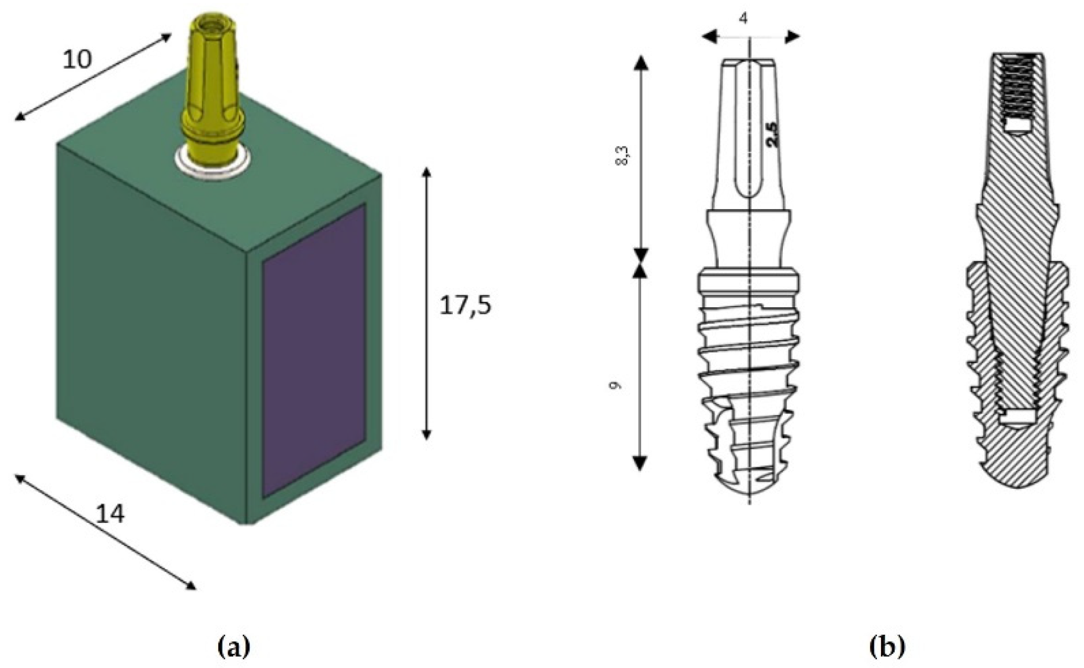
Figure 2.
Implant insertion into the bone model (first line). Implant placement at the equicrestal (0 mm) and subcrestal (-1 mm and -2 mm) levels (second line).
Figure 2.
Implant insertion into the bone model (first line). Implant placement at the equicrestal (0 mm) and subcrestal (-1 mm and -2 mm) levels (second line).
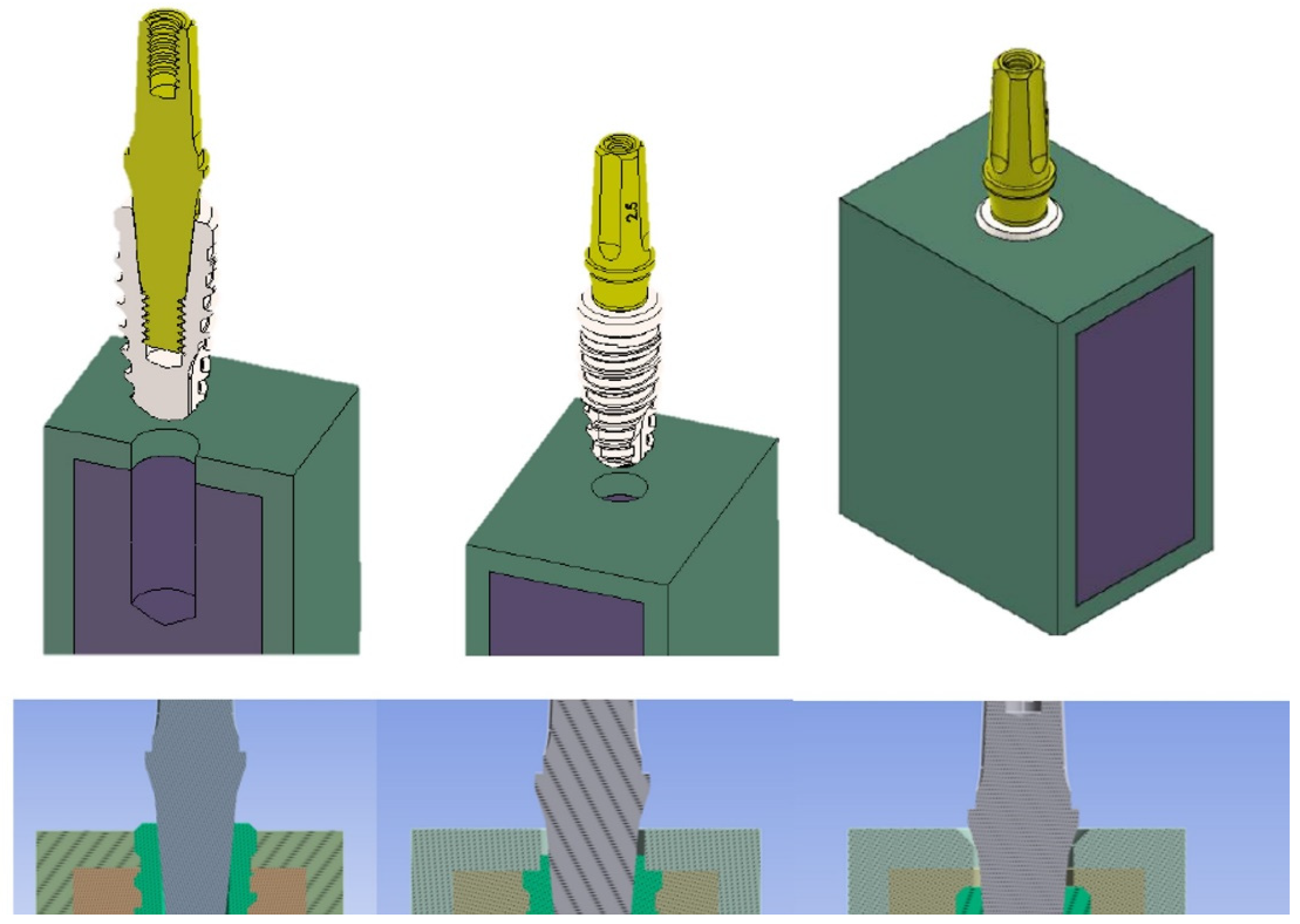
Figure 3.
Loading force of 200 N of magnitude and 45° of inclination applied on the abutment.
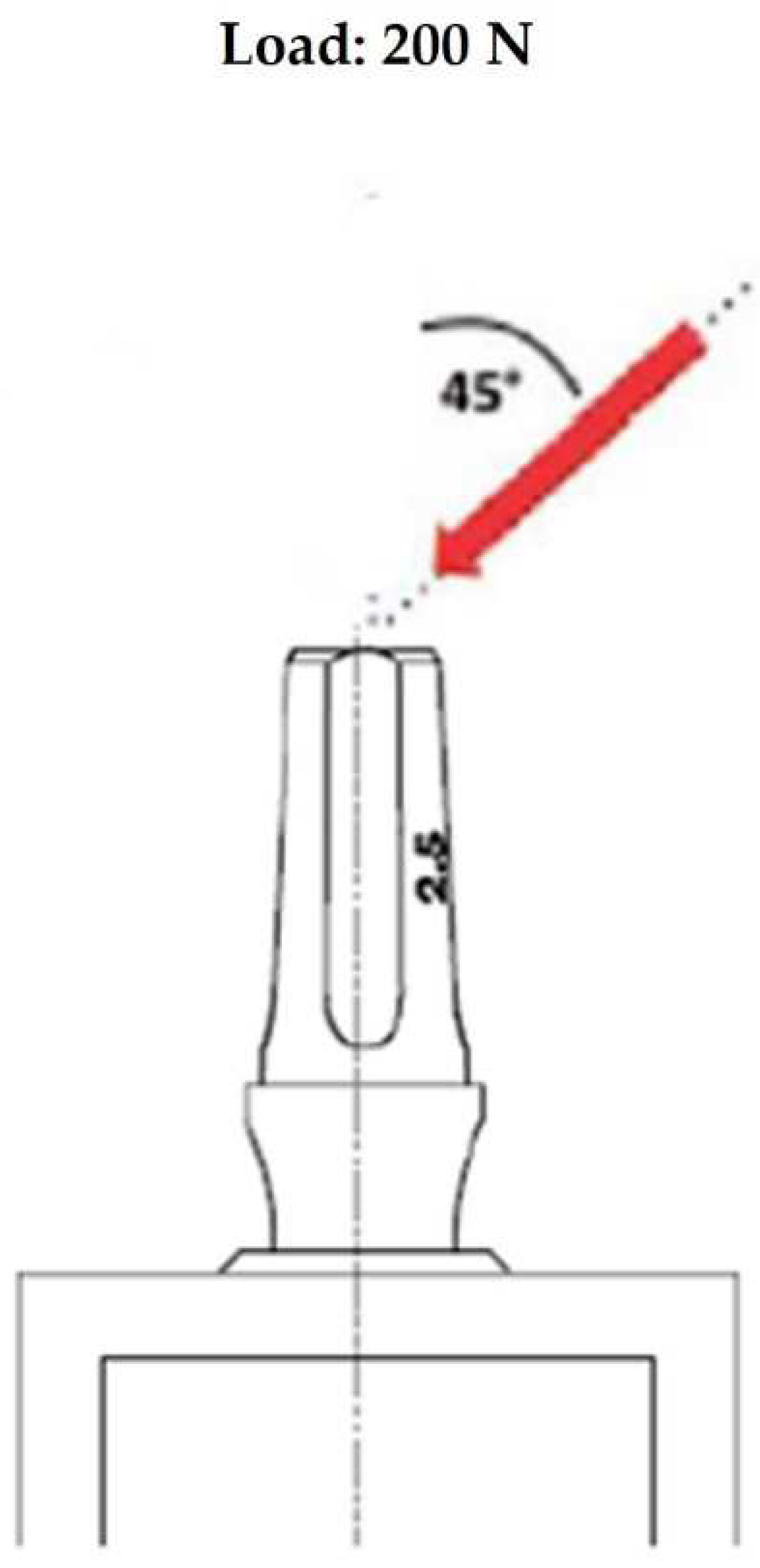
Figure 4.
Mesh size: 0.5 mm and 0.3 mm.
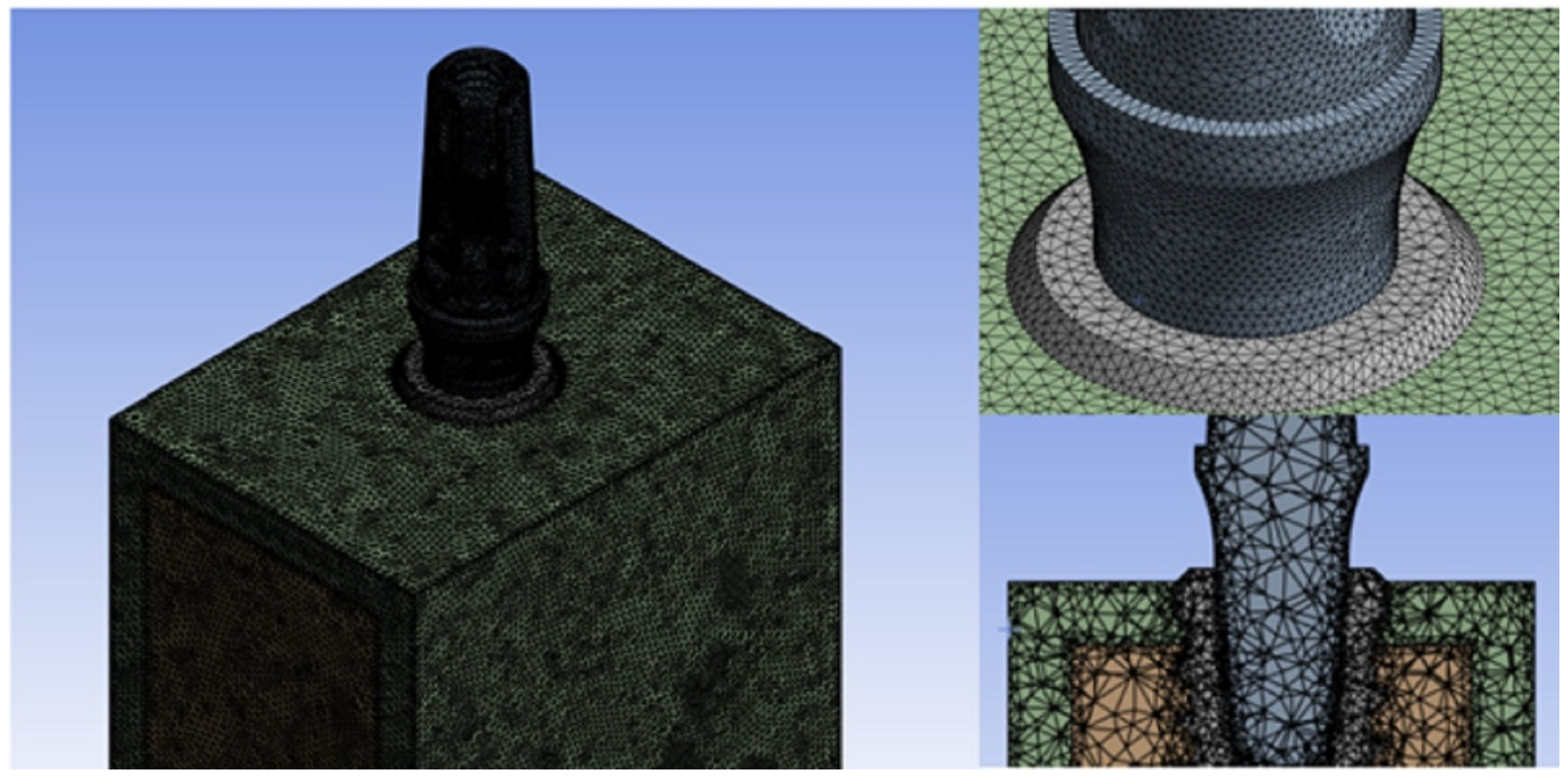
Figure 5.
The implant-abutment contact condition set at 0.3 as frictional coefficient.
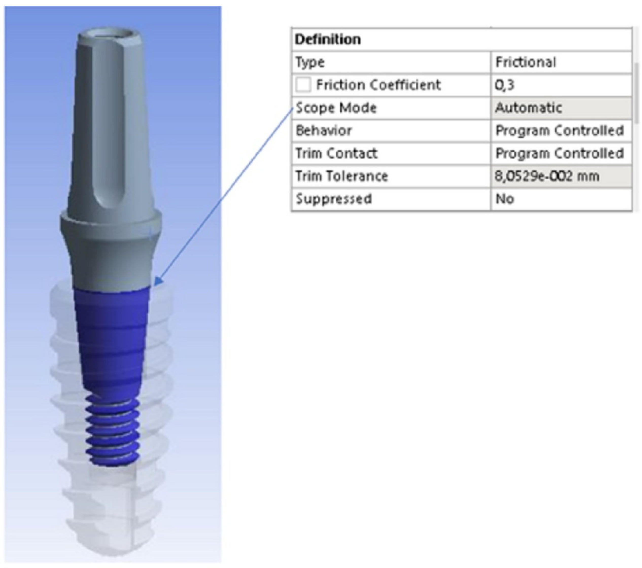
Figure 6.
Von Mises stresses in the three analyzed implant models: (a) equicrestally, (b) subcrestally (-1 mm), and (c) subcrestally (-2 mm) positioned.
Figure 6.
Von Mises stresses in the three analyzed implant models: (a) equicrestally, (b) subcrestally (-1 mm), and (c) subcrestally (-2 mm) positioned.
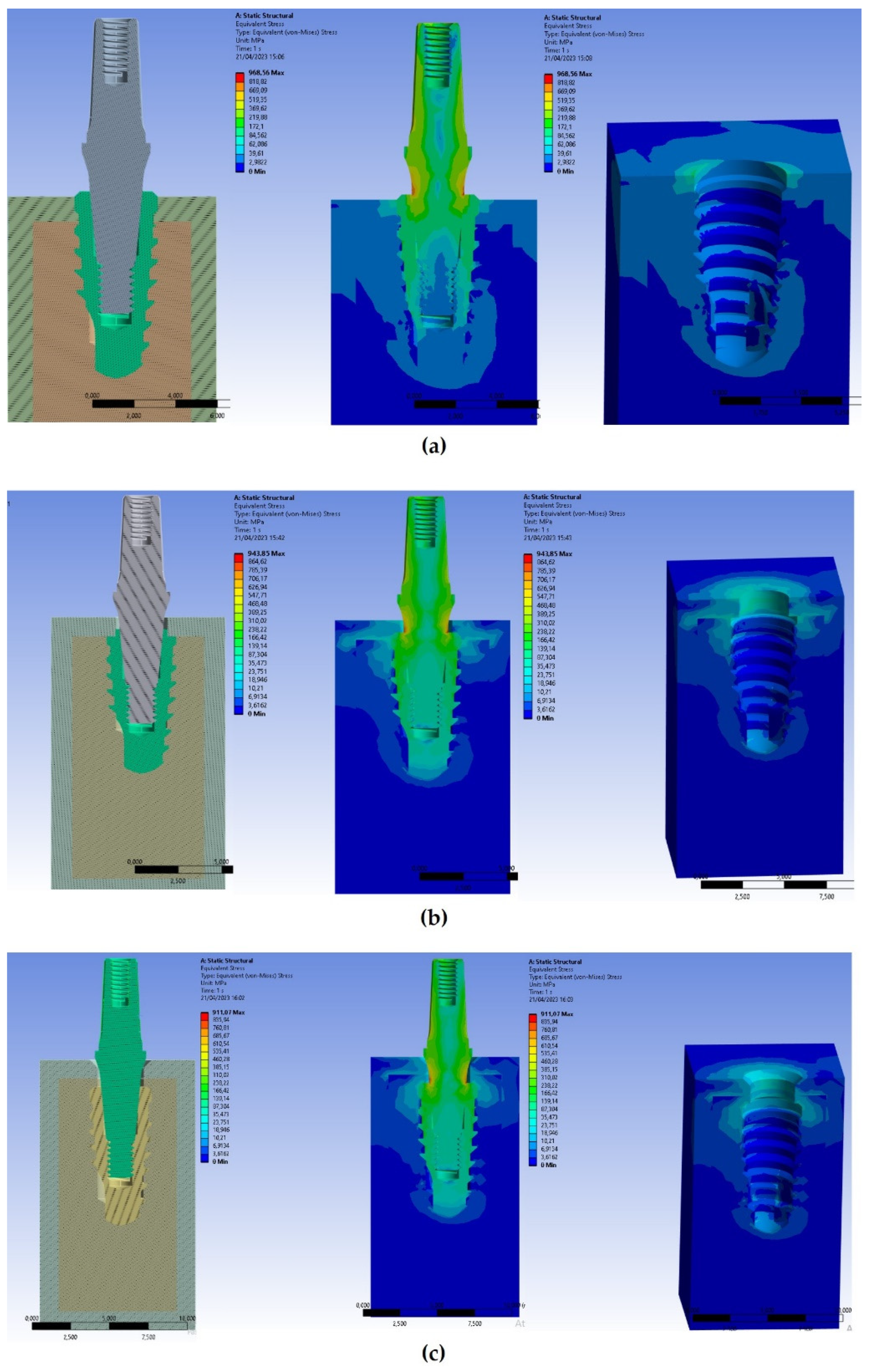
Figure 7.
Comparisons of stresses detected within the bone around equicrestally, 1-mm, and 2-mm subcrestally placed implants.
Figure 7.
Comparisons of stresses detected within the bone around equicrestally, 1-mm, and 2-mm subcrestally placed implants.
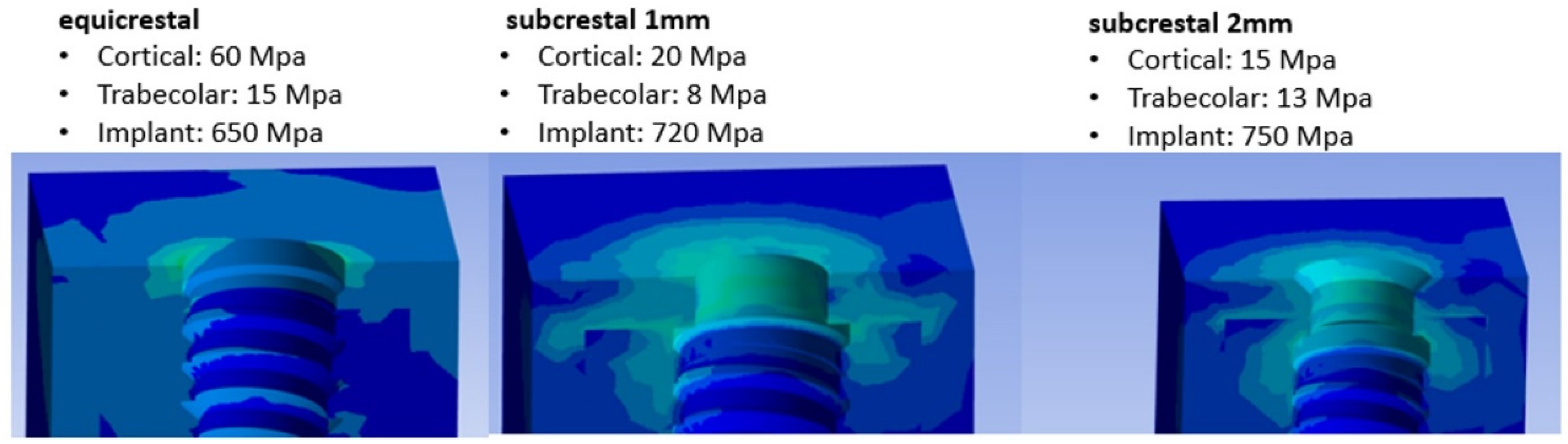

Table 1.
Properties of materials used for this Finite Element Analysis (FEA) study.
| Material | Young’s Modulus (GPa) | Poisson’s Ratio |
|---|---|---|
| Cortical bone | 13.7 | 0.30 |
| Cancellous bone Titanium |
0.3 117 |
0.3 0.30 |
Disclaimer/Publisher’s Note: The statements, opinions and data contained in all publications are solely those of the individual author(s) and contributor(s) and not of MDPI and/or the editor(s). MDPI and/or the editor(s) disclaim responsibility for any injury to people or property resulting from any ideas, methods, instructions or products referred to in the content. |
© 2023 by the authors. Licensee MDPI, Basel, Switzerland. This article is an open access article distributed under the terms and conditions of the Creative Commons Attribution (CC BY) license (http://creativecommons.org/licenses/by/4.0/).
Copyright: This open access article is published under a Creative Commons CC BY 4.0 license, which permit the free download, distribution, and reuse, provided that the author and preprint are cited in any reuse.


