Submitted:
16 June 2023
Posted:
19 June 2023
You are already at the latest version
Abstract
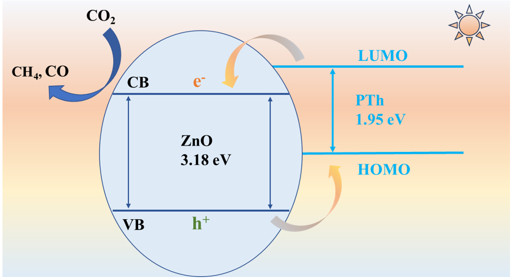
In today's society, mankind is confronted with two major problems: the energy crisis and the greenhouse effect. The artificial photosynthesis can use solar energy to convert greenhouse gas CO2 into high-value compounds, which is an ideal solution to alleviate the energy crisis and solve the problem of global warming. The combination of ZnO and polythiophenes (PTh) can make up for each other's drawbacks, thus improving the photoresponse behavior and separation efficiency of photogenerated carriers. PTh layer can transfer photogenerated electrons to ZnO, thereby extending the lifetime of photogenerated charges. The production rate of CH4 from photoreduction of CO2 with ZnO/PTh10 is 4.3 times that of pure ZnO, and the selectivity of CH4 is increased from 70.2% to 92.2%. The conductive PTh can absorb photons to induce π–π* transition, the photogenerated electrons can transfer from LUMO to the conduction band (CB) of ZnO, thus more electrons involve in the reduction of CO2.
Keywords:
polythiophene
; ZnO
; CO2 reduction
; photocatalysis
; CH4
1. Introduction
“Learning from nature” is one of the main strategies for human social activities. In view of this, it is an ideal method to alleviate the current energy crisis and solve the greenhouse effect by simulating photosynthesis and taking sunlight as the driving force to convert greenhouse gas CO2 into high value-added hydrocarbons [1,2]. Since CO2 molecule is thermodynamic stability with bond energy of C=O up to 750 kJ mol-1, few catalysts can directly reduce it by one electron [3,4]. Nevertheless, the photosynthesis of green plants is a multi-electron and multi-proton process, avoiding the high reduction potential for single electron reduction (-1.9 V vs NHE) [5,6]. Therefore, photocatalysis is also an effective method for achieving CO2 reduction. Predictably, the high-performance photoreduction of CO2 is dependent on photocatalysts with efficient light adsorption, fast photogenerated carriers separation and appropriate redox potential.
Zinc oxide (ZnO) with low toxicity and chemical stability is widely used as gas sensor, solar cell, field-effect transistor, piezoelectric generator, light-emitting diode (LED), photodetector, etc [7]. However, the common drawback of semiconductors is that the high recombination rate of photogenerated charge carriers leading to unconvincing photocatalytic performance [8]. On the other hand, the inherently wide bandgap (3.2 eV) permits activation only in ultraviolet region, restricting the utilization of the clean and abundant solar light [9,10]. In order to make up for ZnO's own shortcomings to suppress the recombination, researchers have taken many measures, such as doping, forming heterojunction, loading noble metals, manufacturing defects and so on [11,12,13]. However, the poor conductivity of ZnO limits the rapid transfer of photogenerated electrons and holes.
Conductive polymer with spatially extended π-conjugated electron system has drawn more and more attention, which may act as a promising alternative to traditional inorganic semiconductor [14]. The preparation of conducting polymers is simple by applying chemical or electrochemical methods. Consequently, conductive polymers have been applied in energy storage, sensors, environmental protection and other fields [15,16]. More importantly, conductive polymer has a small bandgap, which allows to absorb visible light from the sun. Recently, the combination of conductive polymers and semiconductor materials improves the utilization of photogenerated charges, promoting the degradation of dyes and water decomposition [17,18,19]. However, the research of conductive polymers in the field of photocatalysis is not deep enough, and some problems such as the impact on product selectivity are not clear.
Given the above analysis, combining stable inorganic semiconductor ZnO with flexible polymer with good conductivity to study the activity and product selectivity of photocatalytic CO2 reduction. PTh are one class of conductive polymers, which show exceptionally thermal as well as chemical stability, and remarkable optical properties with bandgap of 2.0 eV [20]. Therefore, constructing composite material by polymerizing a layer of thiophene on the surface of ZnO with wide bandgap, which is conducive to accelerating the transfer of photogenerated electrons and improving light absorption capacity. Finally, the production rate of CH4 from photoreduction of CO2 with the composite material is 4.3 times that of pure ZnO, and the selectivity of CH4 is increased from 70.2% to 92.2%.
2. Results and Discussion
2.1. Photocatalyst Characterization
Firstly, porous ZnO nanosheets were prepared using a hydrothermal method [21], as shown in Figure 1a. Subsequently, the thiophene monomers were polymerized on the surface of ZnO in an ice water bath with using ammonium persulfate as a polymerization agent to form the composite material of ZnO/PThx. The TEM image of pure ZnO nanosheets is shown in Figure S1a, and the size distribution of the nanosheets ranges from 300 to 500 nm. The lattice fringe spacings of 0.260 and 0.247 nm in HRTEM images (Figure S1b,c) correspond to the (002) and (101) crystal planes of ZnO, respectively. The high-angle annular dark-field scanning transmission electron microscopy (HAADF-STEM) and corresponding elemental mapping images are shown in Figure S1d-f, which can be clearly observed that ZnO has porous structure and the distribution of Zn and O elements.
The XRD patterns of ZnO and ZnO/PTh10 are displayed in Figure 1b, and ZnO matches well with hexagonal crystal structure (JCPDS No. 70-2551). The high intensity peaks indicate that the synthesized ZnO and ZnO/PTh10 materials have good crystallinity. The crystallinity and characteristic peaks of ZnO materials have not changed significantly before and after the composite of PTh, suggesting the introduction of conductive polymer PTh will not change the crystal structure of ZnO. The slight decrease in the diffraction peak intensity of ZnO/PTh10 may be due to the PTh on the surface masking part of the signals. The TEM image (Figure 1c) shows that there is no significant difference between the morphology of ZnO/PTh10 and pure ZnO, both of which are nanosheets. The lattice spacing of 0.26 nm (Figure 1d) belongs to the (002) crystal plane of ZnO. In addition, a layer of amorphous material with a thickness of 4 nm can be observed on the surface of the composite material, which is assigned to polymer of thiophene. Thus, the thin thickness of this polymer layer will not affect the catalytic ability of ZnO. The HAADF-STEM image of ZnO/PTh10 (Figure 1e) indicates that the porous structure in ZnO remains unchanged. Furthermore, it can be seen that C and S elements contained in PTh are evenly distributed on the surface of ZnO by element mapping analysis of ZnO/PTh10 material (Figure 1f-i).
The infrared spectra of ZnO and ZnO/PTh10 are represented in Figure S2. A broad peak between 3200 and 3700 cm-1 can be observed, which is due to the stretching vibration of hydroxyl group (-OH) generated by the coordination of water molecules with ZnO sample [21]. The peak between 1500 and 1650 cm-1 is attributed to the bending vibration of -OH. A new peak appears near 1100 cm−1 in the spectrum of ZnO/PTh10, which is attributed to the vibration modes of water molecule [21], indicating that ZnO/PTh10 is more hydrophilic, and the PTh formed on the surface can be used as mass transfer channel. The infrared peaks have not changed significantly after the introduction of PTh, which manifests that the core crystal structure of ZnO has not changed, which is consistent with the above XRD analysis result.
In order to study the pores and specific surface area of prepared materials, N2 adsorption-desorption tests were conducted. As shown in Figure 2a, both materials of ZnO and ZnO/PTh10 possess hysteresis loops, and the isotherms belong to IV-type [22], which suggests the as-prepared materials have abundant mesopores. The special surface areas of the as-prepared samples are calculated according to the BET (Brunauer–Emmett–Teller) equation, and the corresponding results are 42 and 51 m2 g-1 for ZnO and ZnO/PTh10 respectively. The pore size distributions of the as-prepared materials are calculated by the Barrett–Joyner–Halenda (BJH) method from the desorption branch of the isotherm curve, and the corresponding results are displayed in Figure 2b, the average pore sizes of ZnO and ZnO/PTh10 are 14.98 and 17.34 nm, respectively. Therefore, the large specific surface area and porous structure are conducive to the transfer of mass and charges.
Ultraviolet-visible spectroscopy (UV-vis) is commonly used to evaluate the light absorption performance of materials. As depicted in Figure 2c, it can be found that ZnO/PTh10 has significantly stronger absorption capacity for photons than ZnO in the wavelength range of 380 to 500 nm. The redshift of composite materials is beneficial for absorption of visible light, which is related to the excitation of PTh from the highest occupied molecular orbital (HOMO) to the lowest unoccupied molecular orbital (LUMO) [23]. The bandgaps were determined by using Tauc/Davis-Mott model with the equation of (αhυ)1/n = A(hυ-Eg) [24]. The value of the exponent n denotes the nature of material and is defined as 0.5 for a directly allowed transition like ZnO. The fitting result reveals that the bandgaps of ZnO and ZnO/PTh10 are approximately 3.18 (close to theoretical value of 3.20 eV) and 3.13 eV (Figure 2d), respectively. The reference values of valence band (EVB) were measured by XPS valence spectra (Figure 2e), and the obtained values are 2.41 and 2.15 eV for ZnO and ZnO/PTh10, respectively. The conduction band values (ECB) can be calculated by the difference between EVB and Eg, and the final results are displayed in Figure 2f. The conduction band potential values of ZnO and ZnO/PTh10 are both lower than the theoretical potentials for reducing CO2 to CO and CH4, thus ZnO and ZnO/PTh10 have the potential to convert CO2 to CO and CH4.
2.2. Efficient Separation of Photogenerated Charges
The XPS was applied to further analyze the effect of PTh introduction on the valence state, chemical composition and surface chemical state of ZnO. There are two characteristic peaks of pure phase ZnO at 1021.1 eV (Zn 2p3/2) and 1044.1 eV (Zn 2p1/2) [25] in Figure 3a. Whereas after adding PTh, the fitting peaks of Zn 2p shift to the direction of small binding energy (1020.9 and 1043.9 eV), which implies that ZnO gains electrons from the PTh layer, resulting in a decrease in the valence state of Zn. The peak at 529.3 eV in the O 1s spectra is attributed to the binding energy of Zn-O in the characteristic hexagonal wurtzite [26,27,28]. And the peak locating at 531.5 eV is related to the bonding of C=O of adsorbed CO2 molecules [26]. When the surface of ZnO is coated with PTh, the fitting peaks of O 1s also shift to the direction of low binding energy, which further confirms that ZnO obtains electrons from the PTh layer. In addition, a new peak appeared at 533.4 eV for ZnO/PTh10, indicating the presence of thiophene energy bonds. Hence, the XPS analysis results certify that the PTh layer can transfer some electrons to ZnO after the composite material being constructed, thus improving the electron density of active sites in ZnO.
Steady-state photoluminescence (PL) spectroscopy is commonly used to investigate the separation efficiency of photogenerated charge carriers between the interfaces. The PL spectra of ZnO and ZnO/PTh10 materials are shown in Figure 3c. Both materials produce emission peaks with similar shapes at 654 nm with the utilization of 325 nm laser as the excitation light source. The emission peak intensity of material containing PTh layer is significantly reduced. In principle, the lower the recombination rate of photogenerated electrons and holes, the lower the intensity of PL emission peak [29,30]. As a result, the separation efficiency of photogenerated charges in ZnO/PTh10 greatly improves after being excited by light, and more electrons can participate in CO2 reduction reaction. The PL decay lifetime was employed to further explore the separation of photogenerated carriers. As presented in Figure 3d, the fitting results indicate that the PL decay lifetime of ZnO/PTh10 is 3.06 ns, which is longer than that of pure ZnO (2.51 ns). The extension of lifetime means that more photogenerated electrons transfer from the PTh layer to ZnO, which is conducive to improving the photoreaction rate as well as product selectivity.
As shown in Figure 3e, the transient photocurrent response curves of ZnO and ZnO/PThx (x= 5, 10, 15) were tested under visible light excitation. The four materials exhibit instantaneous current response when intermittently switching light for five times. The produced photocurrent was mainly the result of photoinduced electrons diffusing to the FTO [31]. Thereupon, the enhanced photocurrent implies that more effective charge transfer is achieved after covering the surface of ZnO with a layer of PTh. Among, ZnO/PTh10 exhibits the strongest light response signals, hence, ZnO/PTh10 is the optimal photocatalyst. The electrochemical impedance spectroscopy (EIS) was further used to verify the above result, and the final result is consistent with the conclusion of photocurrent (Figure S3). To probe the interfacial charge kinetics for photoreduction of CO2, the transient photocurrent responses were measured in the electrolytes saturated with Ar and CO2. As depicted in Figure 3f, the photocurrent in CO2 atmosphere is lower than that in Ar atmosphere, manifesting that the decrease in photocurrent results from the competitive electron transfer from ZnO/PTh10 to the chemisorbed CO2. The efficient electron delivery is advantageous to CO2 activation and reduction process [32].
2.3. Photocatalytic CO2 Reduction Activity
The photocatalytic reduction of CO2 was carried out in the aqueous solution with triethanolamine (TEOA) as the sacrificial agent under photoexcitation. Firstly, by comparing the photocatalytic performance of a series of composite materials with different amounts of PTh, it can be further explained that PTh layer is the key factor to improve the photocatalytic performance of CO2 reduction. As displayed in Figure 4a, compared with pure ZnO, the photocatalysis activities of composite materials are improved in varying degrees after adding different proportions of PTh. Especially, the selectivity of CH4 in the products is significantly increased. And ZnO/PTh10 exhibits the highest catalytic activity, which is consistent with the results of photogenerated charge separation efficiency. The difference in the photocatalytic performance of the composite materials may be due to the influence of the amount of PTh on the surface on the migrate of photogenerated charges and the transfer of reactant molecules. And the suitable amount of coating can maximize the photocatalytic performance without affecting the light absorption ability.
The curves of the amount of reduction products over time are shown in Figure 4b,c. With the extension of time, the rate of CH4 production with ZnO as catalyst gradually decreases, while ZnO/PTh10 has no obvious change, which indicates that the introduction of PTh can reduce the photocorrosion and improve the stability. The production rate of CH4 increases from 5.0 μmol g-1 to 21.4 μmol g-1, the activity of CH4 production over composite material of ZnO/PTh10 is 4.3 times higher than that of ZnO. However, the rate of CO production over ZnO/PTh10 decreases instead, which means that the concentration of photogenerated electrons increases after covering PTh layer, tending to form multi-electron reduction product (CH4) [33]. According to the amount of electron transfer, the selectivity of CH4 increases from 70.2% to 92.2%. The following scientific control were carried out to verify that ZnO/PTh10 was a true photocatalyst. As shown in Figure S4, photocatalyst, CO2 and light are essential conditions for achieving photocatalytic CO2 reduction. In addition, isotopic labeling experiment confirms that the carbon in the reduction products is derived from CO2 (Figure 4d). There are three obvious signal peaks at the mass to charge ratios (m/z) of 17, 29 and 45, which correspond to 13CH4, 13CO and 13CO2, respectively. The cyclic experimental result of ZnO/PTh10 is shown in Figure S5, and the photocatalytic performance did not significantly decrease after four cycles, further proving the high stability of the composite material.
2.4. Photocatalytic Mechanism
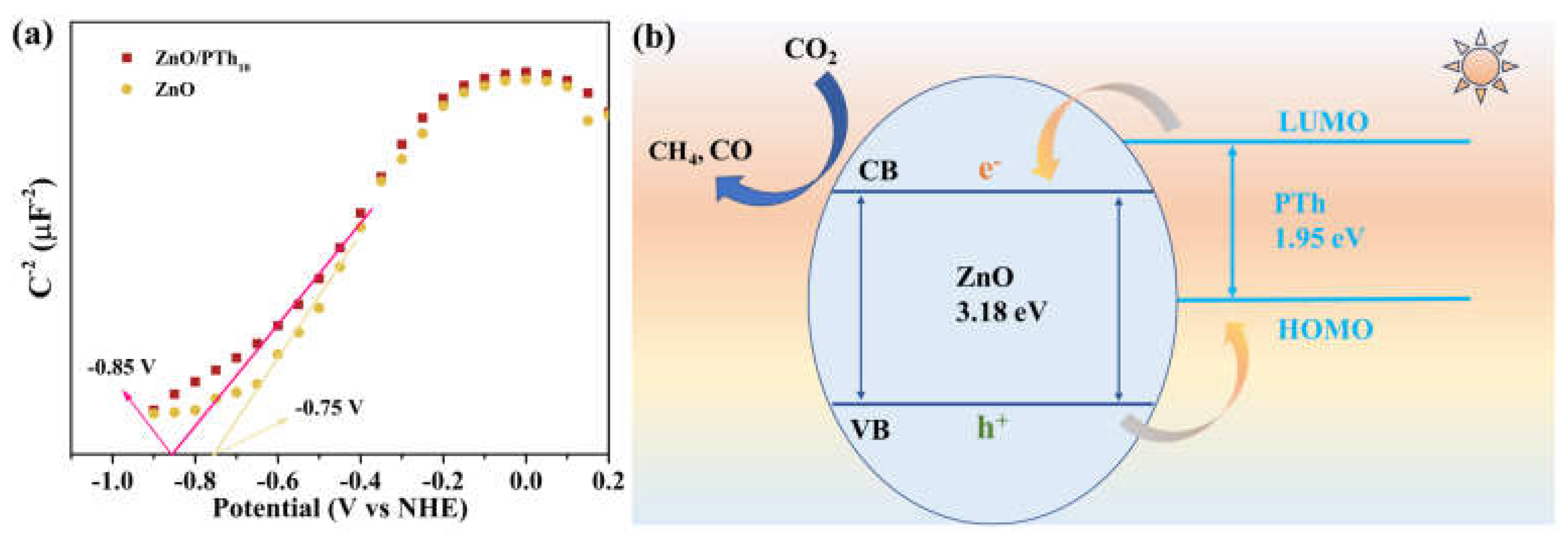
The wide bandgap of ZnO is weak in absorption of visible light, while PTh can generate carriers when excited by light, but the recombination rate of carriers is fast [34]. The combination of ZnO and PTh can make up for each other's shortcomings and improve the photoresponse behavior. The flat-band potentials of ZnO and ZnO/PTh10 were measured by using the Mott–Schottky method (Figure 5a). The obtained potentials of -0.75 V and -0.85 V (vs. NHE, pH 7.0) for ZnO and ZnO/PTh10 respectively indicate that the two photocatalysts possess suitable redox potential to catalyze reduction of CO2 to CO (E= -0.53 V) and CH4 (E= -0.24 V) [35]. The possible photocatalytic mechanism is speculated as shown in Figure 5b. The conductive PTh can absorb photons to induce π–π* transition, the photoexcited electrons generated by PTh are transferred from LUMO to the CB of ZnO and participate in the reduction of CO2 [19]. The holes in the VB of ZnO are transferred to the HOMO of PTh, thus improving the separation efficiency of photogenerated electrons and holes. Ultimately, more photogenerated electrons take part in the reduction reaction, boosting the reduction rate of CO2 and the selectivity of CH4.
3. Materials and Methods
3.1. Materials Preparation
3.1.1. Synthesis of ZnO
In a typical synthesis, 3.45 g of Zn(OAc)2 and 2.5 g of NaOH were dissolved into 80 mL of deionized water under stirring for 2 h. The obtained mixture was transferred into a 100 mL of stainless autoclave and kept at 180 oC for 12 h. Then, the mixture was centrifuged, and the resulting solid was washed several times with acetone and dried. Finally, the obtained sample was calcined at 450 °C for 2 h.
3.1.2. Preparation of ZnO/PThx
1.0 g of ZnO material was uniformly dispersed in 50 mL of ethanol, and a certain amount of monomer thiophene was added under stirring at 0 oC (mass ratios of 1:5, 1:10, and 1:15, respectively). After half an hour, 2 mL of hydrochloric acid solution with containing 0.135 g of ammonium persulfate (pH=2) was added into above mixture. The above mixture was continuously stirred under ice bath conditions, and washed alternately with deionized water and ethanol after stirring 6 h. The obtained solid was dried in a vacuum oven, which was labeled as ZnO/PThx (X=5, 10, 15).
3.2. Characterization
Crystallinity of the samples was obtained by using a Bruker AXS-D8 Advance X-ray diffractometer (XRD) with Cu Kα radiation in the 2θ range of 5–80°. Transmission electron microscopy (TEM) and high-resolution TEM (HRTEM) images were recorded using a JEOL 2100 microscope operated at 200 kV accelerating voltage. Nitrogen adsorption-desorption isotherms were collected using a NOVA1000 nitrogen adsorption apparatus at 77 K. X-ray photoelectron spectroscopy (XPS) was performed using a Kratos Axis Ultra DLD spectrometer with a monochromatic Al Kα X-ray source. Ultraviolet-visible diffuse reflectance spectra (DRS) were recorded on a spectrophotometer (Hitachi UV-3010) using BaSO4 as a reference. Steady-state and time-resolved photoluminescence (PL) spectroscopy (Edinburgh, FS5) was used to get transient spectra of the specimen at room temperature.
Electrochemical measurements were performed with a CHI 660D electrochemical workstation (Chenhua, Shanghai) in a standard three-electrode system. Fluorine-doped tin oxide (FTO) deposited with the as-prepared sample served as a working electrode with an active area of 1.0 cm2, while the counter and the reference electrodes were graphite and saturated calomel electrode, respectively. Time-dependent photocurrent measurements were performed using a 300 W Xe lamp equipped with an ultraviolet cut off filter (λ ≥ 420 nm). The Mott-Schottky curves were recorded at a fixed frequency of 1000 Hz with 5 mV amplitude. The electrochemical impedance spectroscopies (EIS) were recorded in the frequency range from 10 kHz to 0.01 Hz, and the applied bias voltage and ac amplitude were set at open-circuit voltage. A 0.5 M Na2SO4 aqueous solution was used as electrolyte.
3.3. Photocatalytic Tests
The photocatalytic CO2 reduction reaction was carried out in a 55 mL of quartz tube, and the products were tested using gas chromatograph with TCD and FID detectors. Firstly, 10 mg of photocatalyst, 10 mL of deionized water, and 1 mL of triethanolamine (TEOA) were added to the quartz tube, subsequently, the quartz tube was subjected to ultrasonic treatment for 15 min to evenly disperse the material. Then, high purity CO2 (99.999%) was bubbled into the quartz tube, and after 30 minutes the quartz tube was completely sealed using a silicone plug and sealing film. The sealed quartz tube was illustrated with white LED lamps with the power of 200 W. During this period, the products in the quartz tube were detected and analyzed every 1 h.
4. Conclusions
Conductive polymer with spatially extended π-conjugated electron system is beneficial for rapid transfer of electrons. The combination of ZnO and PTh can compensate for the shortcomings of broad bandgap and easy recombination of photogenerated carriers. The experimental results of photocurrent and EIS show that the separation efficiency of photogenerated charge is the highest when the thickness of PTh layer is 4 nm (ZnO/PTh10). The increase in specific surface area and average pore size of ZnO/PTh10 is conducive to the transfer of mass and charges. The PTh layer can transfer electrons to ZnO by XPS analysis, thus the lifetime of photogenerated is lengthened, which is beneficial to boost photocatalytic activity. Analysis of band structure and flat-band potentials indicate that ZnO/PTh10 can reduce CO2 to CO and CH4. Finally, the production rate and selectivity of CH4 have greatly improved.
Supplementary Materials
The following supporting information can be downloaded at the website of this paper posted on Preprints.org, Figure S1: TEM images of ZnO; Figure S2: Infrared spectra of ZnO and ZnO/PTh10; Figure S3: Nyquist plots of ZnO and ZnO/PThx; Figure S4: Effect of different reaction conditions on the photocatalytic activity of ZnO/PTh10; Figure S5: Cycle test for ZnO/PTh10.
Author Contributions
Investigation, experimental work, analysis and discussion, data curation, writing, Y.D.; methodology, software, formal analysis, L.T.; characterization, analysis and discussion, P.W.; analysis and discussion, S.C.; data curation, M.Z.; writing—review and editing, funding acquisition, Y.X.; supervision, writing—review and editing, funding acquisition, project administration, W.D. All authors have read and agreed to the published version of the manuscript.
Funding
This research was financially supported by the Guangdong Provincial Science and Technology innovation strategy Project (Grant No. 2022DZXHT021), Maoming Science and Technology Special Project (Grant No. 2022S049), 2022 "Sail Plan" Project of Maoming Green Chemical Industry Research Institute (Grant No. MMGCIRI-2022YFJH-Z-001), Jiangxi Provincial Natural Science Foundation (Grant Nos. 20224BAB214026 and 20224ACB203001), Key Research and Development Program of Jiangxi Province (Grant No. 20192ACB70009).
Data Availability Statement
The data presented in this study are available on request from the corresponding author.
Acknowledgments
The authors are grateful for the financial support received for the project.
Conflicts of Interest
The authors declare no conflict of interest.
References
- Kim, R.; Kim, J.; Do, J.Y.; Seo, M.W.; Kang, M. Carbon Dioxide Photoreduction on the Bi2S3/MoS2 Catalyst. Catalysts 2019, 9, 998. [Google Scholar] [CrossRef]
- Dai, W.; Wang, P.; Long, J.; Xu, Y.; Zhang, M.; Yang, L.; Zou, J.; Luo, X.; Luo, S. Constructing Robust Bi Active Sites In Situ on α-Bi2O3 for Efficient and Selective Photoreduction of CO2 to CH4 via Directional Transfer of Electrons. ACS Catal. 2023, 13, 2513–2522. [Google Scholar] [CrossRef]
- Li, X.; Wang, S.; Li, L.; Zu, X.; Sun, Y.; Xie, Y. Opportunity of Atomically Thin Two-Dimensional Catalysts for Promoting CO2 Electroreduction. Acc. Chem. Res. 2020, 53, 2964–2974. [Google Scholar] [CrossRef] [PubMed]
- Albero, J.; Peng, Y.; García, H. Photocatalytic CO2 Reduction to C2+ Products. ACS Catal. 2020, 10, 5734–5749. [Google Scholar] [CrossRef]
- Xu, Y.; Long, J.; Tu, L.; Dai, W.; Zou, J.; Luo, X. CoO Engineered Co9S8 Catalyst for CO2 Photoreduction with Accelerated Electron Transfer Endowed by the Built-in Electric Field. Chem. Eng. J. 2021, 426, 131849. [Google Scholar] [CrossRef]
- Habisreutinger, S.N.; Schmidt-Mende, L.; Stolarczyk, J.K. Photocatalytic reduction of CO2 on TiO2 and other semiconductors. Angew. Chem. Int. Ed. 2013, 52, 7372–7048. [Google Scholar] [CrossRef]
- Noman, M.T.; Amor, N.; Petru, M. Synthesis and applications of ZnO nanostructures (ZONSs): a review. Crit. Rev. Solid State 2021, 47, 99–141. [Google Scholar] [CrossRef]
- Mahlangu, O.T.; Mamba, G.; Mamba, B.B. A facile synthesis approach for GO-ZnO/PES ultrafiltration mixed matrix photocatalytic membranes for dye removal in water: Leveraging the synergy between photocatalysis and membrane filtration. J. Environ. Chem. Eng. 2023, 11, 110065. [Google Scholar] [CrossRef]
- Rosman, N.; Norharyati Wan Salleh, W.; Aqilah Mohd Razali, N.; Nurain Ahmad, S.Z. Ibuprofen removal through photocatalytic filtration using antifouling PVDF- ZnO/Ag2CO3/Ag2O nanocomposite membrane. Mater. Today Proc. 2021, 42, 69–74. [Google Scholar] [CrossRef]
- Irani, E.; Amoli-Diva, M. Hybrid adsorption–photocatalysis properties of quaternary magneto-plasmonic ZnO/MWCNTs nanocomposite for applying synergistic photocatalytic removal and membrane filtration in industrial wastewater treatment. J. Photochem. Photobiol. A Chem. 2020, 391, 112359. [Google Scholar] [CrossRef]
- Wu, H.; Lin, S.; Chen, C.; Liang, W.; Liu, X.; Yang, H. A new ZnO/rGO/polyaniline ternary nanocomposite as photocatalyst with improved photocatalytic activity. Mater. Res. Bull. 2016, 83, 434–441. [Google Scholar] [CrossRef]
- Rajakumaran, R.; Boddu, V.; Kumar, M.; Shalaby, M.S.; Abdallah, H.; Chetty, R. Effect of ZnO morphology on GO-ZnO modified polyamide reverse osmosis membranes for desalination. Desalination 2019, 467, 245–256. [Google Scholar] [CrossRef]
- Dao, T.T.; Vo, T.L.N.; Duong, A.T.; Tran, D.T.; Nguyen, D.L.; Pham, V.V.; Das, R.; Nguyen, H.T. Highly photocatalytic activity of pH-controlled ZnO nanoflakes. Opt. Mater. 2023, 140, 113865. [Google Scholar] [CrossRef]
- Zhou, Q.; Shi, G. Conducting Polymer-Based Catalysts. J. Am. Chem. Soc. 2016, 138, 2868–2876. [Google Scholar] [CrossRef]
- Tran, V.V.; Tran, N.H.T.; Hwang, H.S.; Chang, M. Development strategies of conducting polymer-based electrochemical biosensors for virus biomarkers: Potential for rapid COVID-19 detection. Biosens. Bioelectron. 2021, 182, 113192. [Google Scholar] [CrossRef]
- Ognibene, G.; Gangemi, C.M.A.; Spitaleri, L.; Gulino, A.; Purrello, R.; Cicala, G.; Fragalà, M.E. Role of the surface composition of the polyethersulfone–TiiP–H2T4 fibers on lead removal: From electrostatic to coordinative binding. J. Mater. Sci. 2019, 54, 8023–8033. [Google Scholar] [CrossRef]
- Liao, G.Z.; Chen, S.; Quan, X.; Chen, H.; Zhang, Y.B. Photonic crystal coupled TiO2/polymer hybrid for efficient photocatalysis under visible light irradiation. Environ. Sci. Technol. 2010, 44, 3481–3485. [Google Scholar] [CrossRef] [PubMed]
- Kanade, K.G.; Baeg, J.O.K.; Mulik, U.P.; Amalnerkar, D.P. Nano-CdS by polymer-inorganic solid-state reaction: visible light pristine photocatalyst for hydrogen generation. Mater. Res. Bull. 2006, 41, 2219–2225. [Google Scholar] [CrossRef]
- Dai, W.; Xu, H.; Yu, J.; Hu, X.; Luo, X.; Tu, X.; Yang, L. Photocatalytic reduction of CO2 into methanol and ethanol over conducting polymers modified Bi2WO6 microspheres under visible light. Appl. Surf. Sci. 2015, 356, 173–180. [Google Scholar] [CrossRef]
- Garg, S.; Goel, N. Photodegradation of dye using Polythiophene/ZnO nanocomposite: A computational approach. J. Mol. Graph. Model. 2022, 117, 108285. [Google Scholar] [CrossRef]
- Arul Hency Sheela, J.; Lakshmanan, S.; Manikandan, A.; Arul Antony, S. Structural, Morphological and Optical Properties of ZnO, ZnO:Ni2+ and ZnO:Co2+ Nanostructures by Hydrothermal Process and Their Photocatalytic Activity. J. Inorg. Organomet. P. 2018, 28, 2388–2398. [Google Scholar] [CrossRef]
- Li, X.; Li, X.; Zhu, B.; Wang, J.; Lan, H.; Chen, X. Synthesis of porous ZnS, ZnO and ZnS/ZnO nanosheets and their photocatalytic properties. RCS Adv. 2017, 7, 30956. [Google Scholar] [CrossRef]
- Xu, S.; Li, S.; Wei, Y.; Zhang, L.; Xu, F. Improving the photocatalytic performance of conducting polymer polythiophene sensitized TiO2 nanoparticles under sunlight irradiation. Reac. Kinet. Mech. Cat. 2010, 101, 237–249. [Google Scholar] [CrossRef]
- Butler, M.A. Photoelectrolysis and physical properties of the semiconducting electrode WO3. J. Appl. Phys. 1977, 48, 1914–1920. [Google Scholar] [CrossRef]
- Xue, L.; Zhang, C.; Shi, T.; Liu, S.; Zhang, H.; Sun, M.; Liu, F.; Liu, Y.; Wang, Y.; Gu, X.; Zeng, S. Unraveling the improved CO2 adsorption and COOH* formation over Cu-decorated ZnO nanosheets for CO2 reduction toward CO. Chem Eng J 2023, 452, 139701. [Google Scholar] [CrossRef]
- Byzynski, G.; Melo, G.; Volanti, D.P.; Ferrer, M.M.; Gouveia, A.F.; Ribeiro, C.; Andrés, J.; Longo, E. The interplay between morphology and photocatalytic activity in ZnO and N-doped ZnO crystals. Mater. Design 2017, 120, 363–375. [Google Scholar] [CrossRef]
- Gao, Y.K.; Traeger, F.; Wöll, C.; Idriss, H. Glycine adsorption and photo-reaction over ZnO(000ī) single crystal. Surf. Sci. 2014, 624, 112–117. [Google Scholar] [CrossRef]
- Jilani, A.; Iqbal, J.; Rafique, S.; Abdel-wahab, M.S.; Jamil, Y.; AlGhamdi, A.A. Morphological, optical and X-ray photoelectron chemical state shift investigations of ZnO thin films. Opt.-Int. J. Light Electron Opt. 2016, 127, 6358–6365. [Google Scholar] [CrossRef]
- Wang, Z.; Jiao, X.; Chen, D.; Li, C.; Zhang, M. Porous Copper/Zinc Bimetallic Oxides Derived from MOFs for Efficient Photocatalytic Reduction of CO2 to Methanol. Catalysts 2010, 10, 1127. [Google Scholar] [CrossRef]
- Yang, Z.; Yang, J.; Yang, K.; Zhu, X.; Zhong, K.; Zhang, M.; Ji. H.; He, M.; Li, H.; Xu, H. Synergistic Effect in Plasmonic CuAu Alloys as Co-Catalyst on SnIn4S8 for Boosted Solar-Driven CO2 Reduction. Catalysts 2020, 12, 1588. [Google Scholar] [CrossRef]
- Xu. Y.; Fu, Z.; Cao, S.; Chen, Y.; Fu, W. Highly selective oxidation of sulfides on a CdS/C3N4 catalyst with dioxygen under visible-light irradiation. Catal. Sci. Technol. 2017, 7, 587–595. [Google Scholar] [CrossRef]
- Chang, X.; Wang, T.; Gong, J. CO2 photo-reduction: insights into CO2 activation and reaction on surfaces of photocatalysts. Energy Environ. Sci. 2016, 9, 2177–2196. [Google Scholar] [CrossRef]
- Shanmugam, M.; Augustin, A.; Mohan, S.; Honnappa, B.; Chuaicham, C.; Rajendran, S.; Hoang, T.K.A.; Sasaki, K.; Sekar, K. Conducting polymeric nanocomposites: A review in solar fuel applications. Fuel 2022, 325, 124899. [Google Scholar] [CrossRef]
- White, M.S.; Olson, D.C.; Kopidakis, N.; Nardes, A.; Ginley, D.S.; Berry, J.J. Control of charge separation by electric field manipulation in polymer-oxide hybrid organic photovoltaic bilayer devices. Phys. Status Solidi A 2010, 207, 1257–1265. [Google Scholar] [CrossRef]
- Chang, X.; Wang, T.; Gong, J. CO2 photo-reduction: insights into CO2 activation and reaction on surfaces of photocatalysts. Energy Environ. Sci. 2016, 9, 2177–2196. [Google Scholar] [CrossRef]
Figure 1.
Schematic diagram of preparation of ZnO/PThx (a). XRD patterns of ZnO and ZnO/PTh10 (b). TEM image of ZnO/PTh10 (c) and HRTEM image of ZnO/PTh10 (d). HAADF-STEM of ZnO/PTh10 (e) and corresponding elemental mapping images (f-i).
Figure 1.
Schematic diagram of preparation of ZnO/PThx (a). XRD patterns of ZnO and ZnO/PTh10 (b). TEM image of ZnO/PTh10 (c) and HRTEM image of ZnO/PTh10 (d). HAADF-STEM of ZnO/PTh10 (e) and corresponding elemental mapping images (f-i).
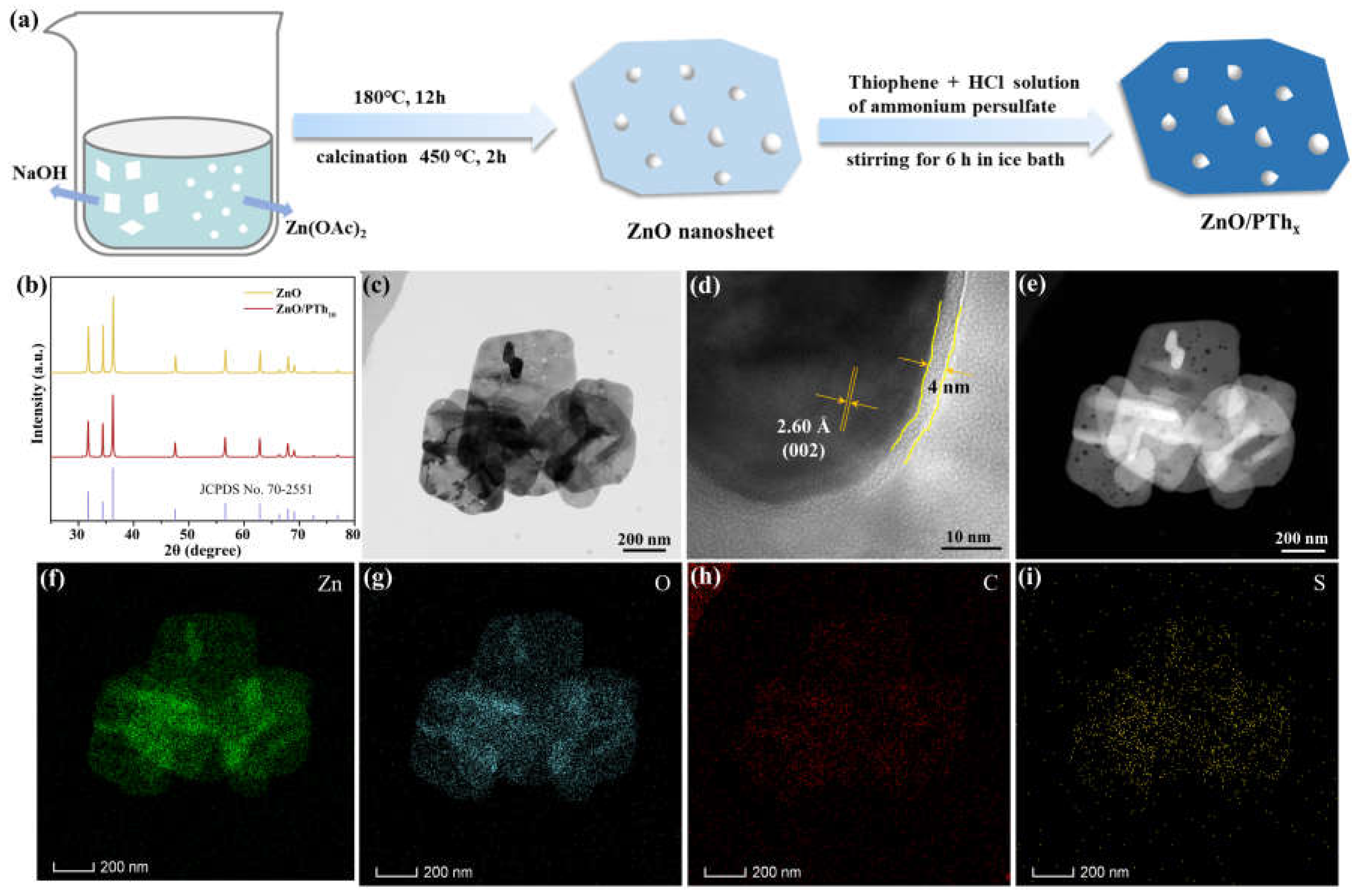
Figure 2.
N2 adsorption-desorption isotherm diagrams of ZnO and ZnO/PTh10 (a), and corresponding pore size distribution (b). Ultraviolet-visible DRS of ZnO and ZnO/PTh10 (c), and corresponding plots of (αhν)2 versus energy (hν) for the band gap energy (d). Valence band XPS spectra (e). Band structure alignments of ZnO and ZnO/PTh10 (f).
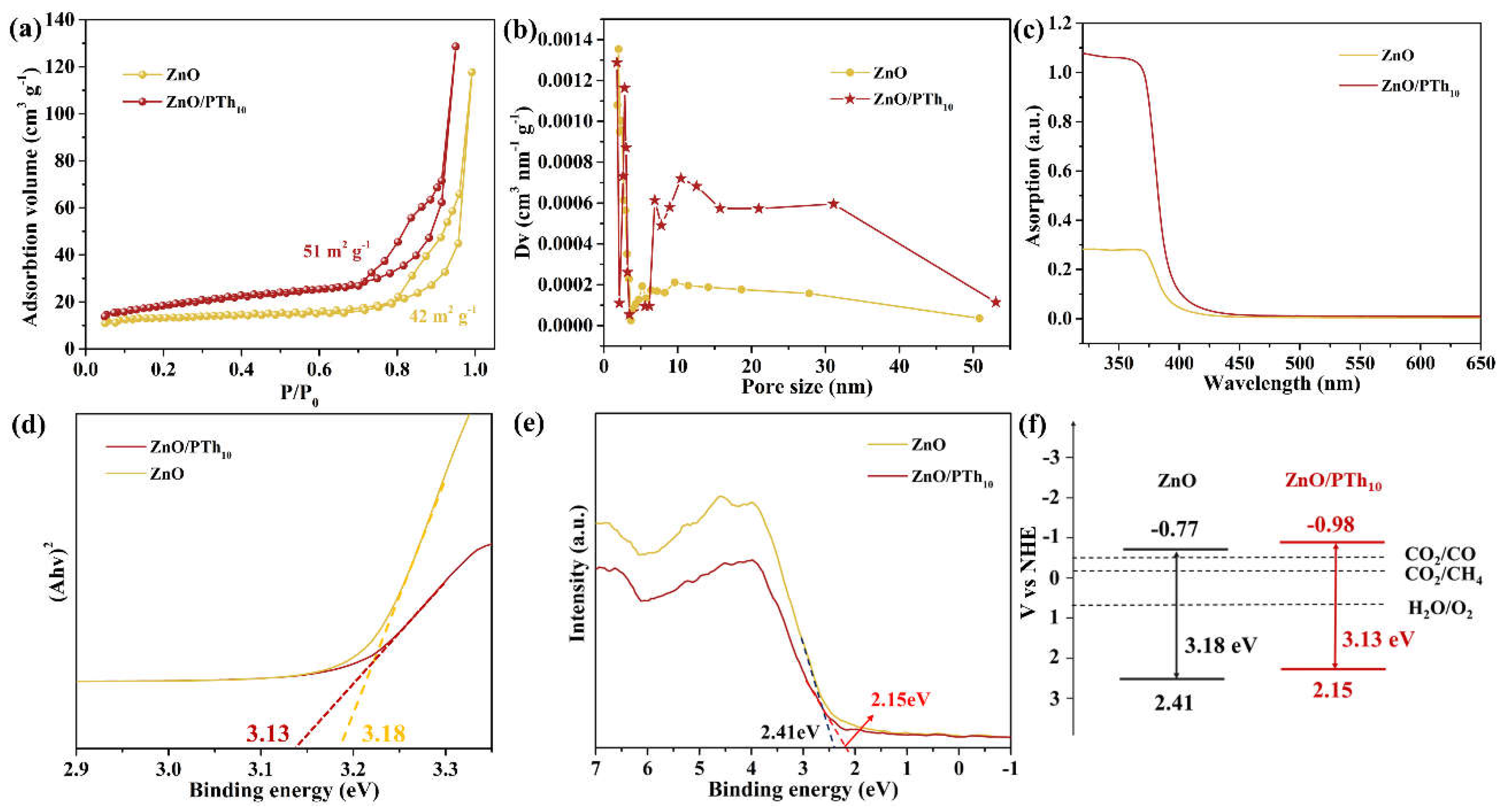
Figure 3.
High-resolution XPS spectra of (a) Zn 2p and (b) O 1s. Steady-state PL spectra (c) and time-resolved PL decay spectra (d) for ZnO and ZnO/PTh10. (e) Transient photocurrent spectra. (f) Transient photocurrent spectra with ZnO/PTh10 as catalyst under the atmosphere of Ar and CO2.
Figure 3.
High-resolution XPS spectra of (a) Zn 2p and (b) O 1s. Steady-state PL spectra (c) and time-resolved PL decay spectra (d) for ZnO and ZnO/PTh10. (e) Transient photocurrent spectra. (f) Transient photocurrent spectra with ZnO/PTh10 as catalyst under the atmosphere of Ar and CO2.
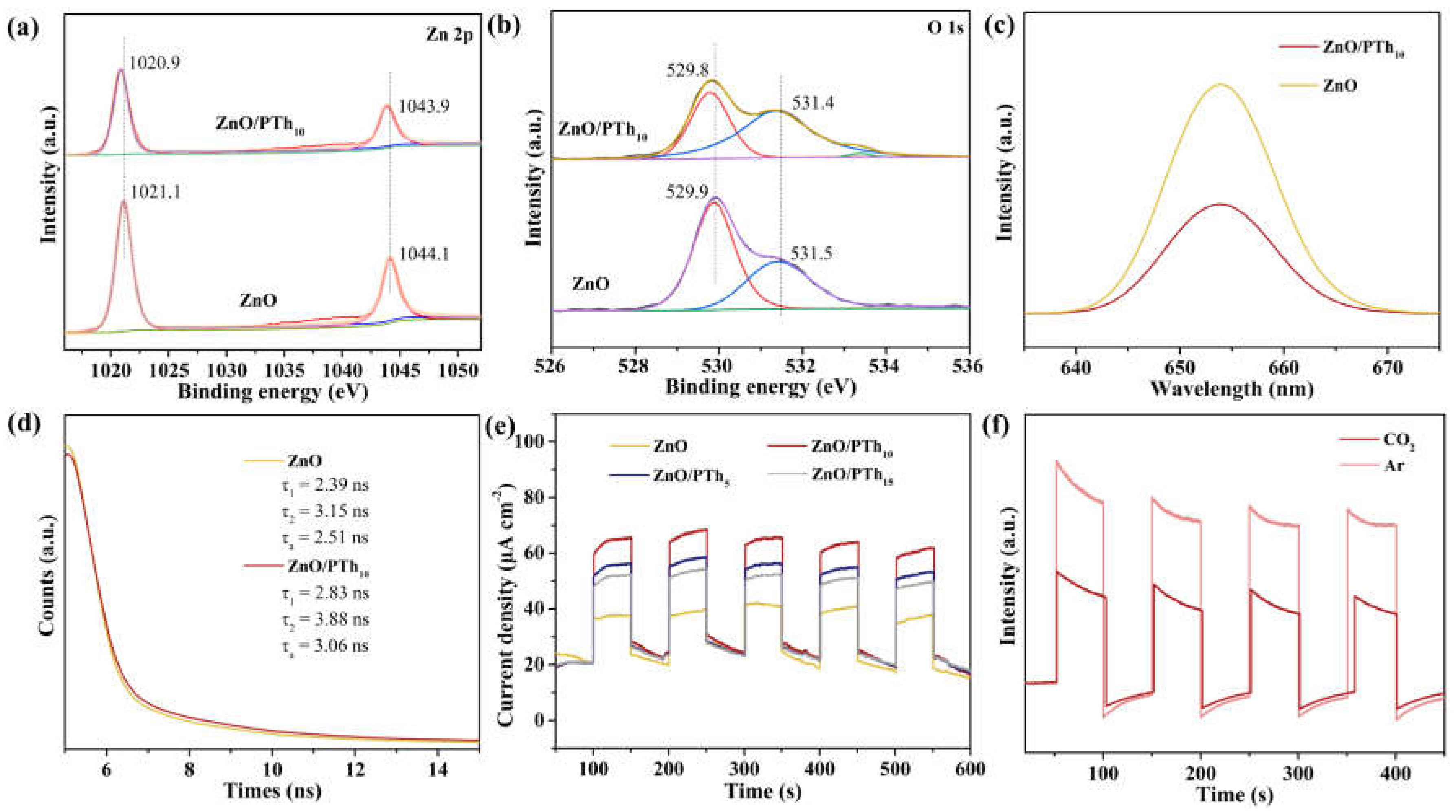
Figure 4.
The effect of different PTh loadings on the photocatalytic activity of ZnO (a). The amount of CH4 (b) and CO (c) produced by photocatalytic reduction of CO2 over time. (d) Mass spectrometry analysis of reduction products.
Figure 4.
The effect of different PTh loadings on the photocatalytic activity of ZnO (a). The amount of CH4 (b) and CO (c) produced by photocatalytic reduction of CO2 over time. (d) Mass spectrometry analysis of reduction products.
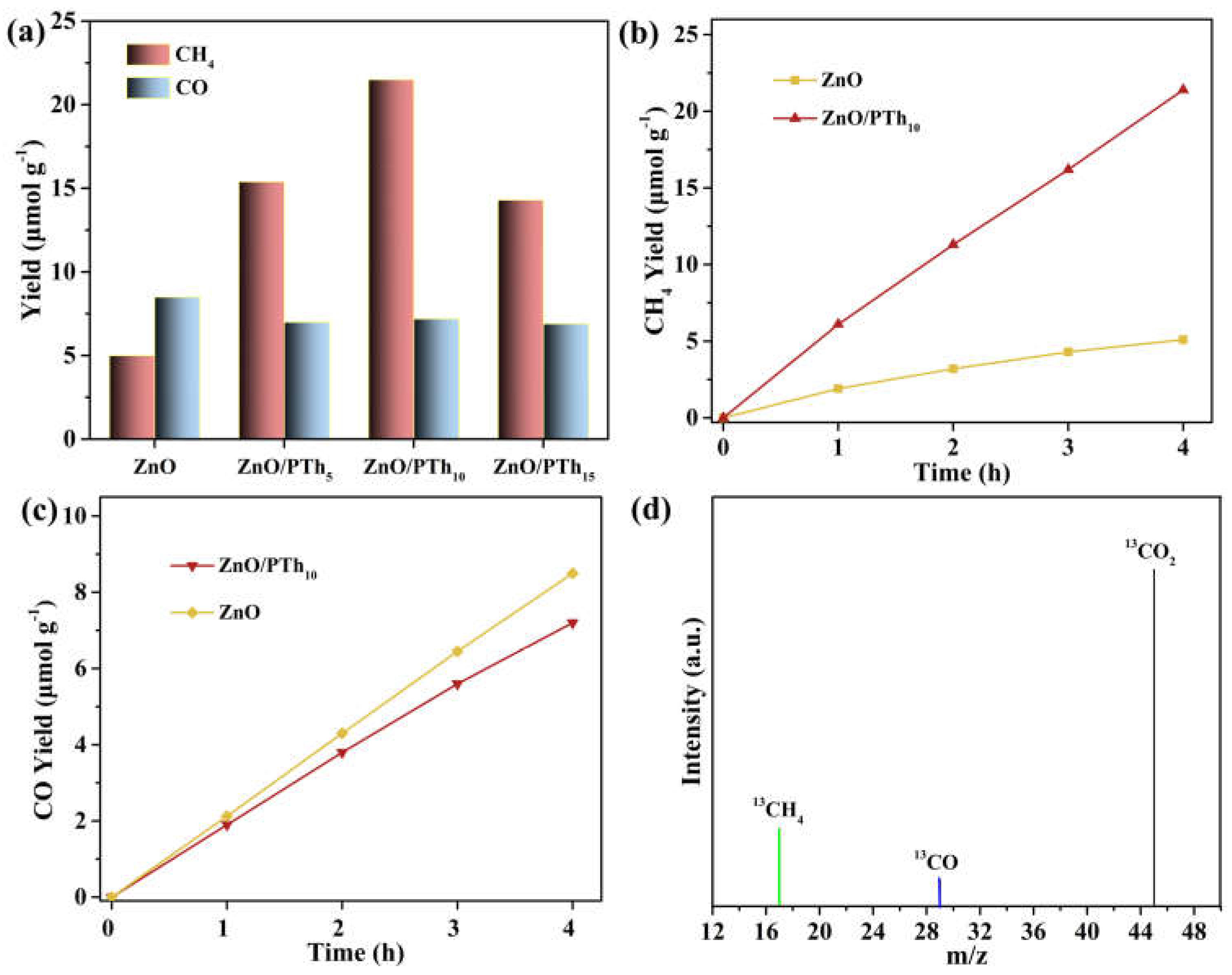
Figure 5.
(a) Mott-Schottky plots of ZnO and ZnO/PTh10. (b) Speculated mechanism for photocatalytic reduction of CO2 over ZnO/PTh10 under visible light irradiation.
Figure 5.
(a) Mott-Schottky plots of ZnO and ZnO/PTh10. (b) Speculated mechanism for photocatalytic reduction of CO2 over ZnO/PTh10 under visible light irradiation.
Disclaimer/Publisher’s Note: The statements, opinions and data contained in all publications are solely those of the individual author(s) and contributor(s) and not of MDPI and/or the editor(s). MDPI and/or the editor(s) disclaim responsibility for any injury to people or property resulting from any ideas, methods, instructions or products referred to in the content. |
© 2023 by the authors. Licensee MDPI, Basel, Switzerland. This article is an open access article distributed under the terms and conditions of the Creative Commons Attribution (CC BY) license (http://creativecommons.org/licenses/by/4.0/).
Copyright: This open access article is published under a Creative Commons CC BY 4.0 license, which permit the free download, distribution, and reuse, provided that the author and preprint are cited in any reuse.


