
Submitted:
12 June 2023
Posted:
13 June 2023
You are already at the latest version
Abstract
This research deals with the processing of wood using a circular saw, which is associated with several risks and factors that affect the wood splitting process. One of them is the wear of the teeth of the saw blade and the change in the size of the cutting forces. The aim of this study is to compare real measured values and theoretical values when processing Norway Spruce wood, using two types of saw blades SK and HSS with a diameter of 600 mm and the number of teeth 54 and 56. Experimental measurements were carried out on a special test device with the possibility of moving the tested wood into the cutting devices and a simple saw blade replacement system. The results of the contributions show significant differences, based on defined factors, which are supported by FEM analysis of cutting forces in the process of cutting wood - when changing the design of the saw blade. The results of the experiment show that the cutting conditions (cutting speed, feed speed) do not have a significant effect on the size of the cutting forces. The theoretical and real stress values for HSS discs ranged from 14 to 22 MPa. Significantly larger differences were recorded for discs with SK, where the real values of the maximum stresses were around 14 MPa and the theoretical ones around 25 MPa. When cutting spruce with a disc with SK slices, the maximum values of the the-oretical cutting forces were in the range of 76 to 94 N and the maximum values of the measured cutting forces were in the range of 40 to 44 N.
Keywords:
les
; drevo
; pílový kotúč
; rezná sila
; MKP analýza
1. Introduction
In the woodworking industry, cutting with circular saws is among the most widespread methods of splitting wood and wood materials, in which the by-product is chips (sawdust). Circular saws are used primarily for cross-cutting [1]. It is actually a physical process that is significantly influenced by a large number of factors in various combinations. Knowledge of these factors is essential for achieving high economy, productivity and optimal machining quality. Gearing, which is the functional part of the tool itself, consists of a smaller or larger number of teeth arranged one behind the other so that their tips lie on the circumference of the cutting circle. Their basic function is to remove the chip from the machined material and its subsequent removal from the cutting gap. Due to the position of the cutting tool in relation to the cut fibers, cutting is divided into longitudinal, transversely and tangentially [2,3]. The research of cutting processes is of great importance, while today there are increasingly high demands for safety at work, automation, increasing the service life of cutting tools, reducing the energy consumption of machines and the associated cost reduction. One of the main parameters affecting the energy demand is the size of the cutting forces acting between the tool and the workpiece. The magnitudes of these forces can be expressed using theoretical relations or directly by experimental measurement, which provides the most accurate data [4]. Circular sawing is one of the most modern technologies in the woodworking industry. Saw blades are designed as universal sweeping blades for longitudinal or transverse cutting or trimming of all types of wood, soft or hard, dry or wet. The use of saw blades is different, especially with single or multiple cutting with a single or double shaft or in splitting machines. Circular sawing has been the center of attention of many researchers due to its wide use [5].
Sawing is a composite process of shearing and cutting. With this process, we remove chips (sawdust), which happens when external cutting forces are applied, overcoming the strength of wood in compression and shear. Many factors affect the sawing process. Understanding these factors and their mutual interactions will help us to fully understand the very principle of sawing. Familiarization with this issue will help us to eliminate undesirable effects with cross-sawing itself, losses of wood raw material and thus improve cross-sawing from an economic point of view. The woodworking industry in Slovakia is one of the few industries that develops on the basis of the domestic raw material base. Wood in our forests is still a reproducible raw material [2,6]. Currently, there is an effort towards ecological and complex utilization of the processed raw material. Recently, the modernization of machinery, which is conditioned by the development of new materials, has been highlighted in the global sawmill industry. So we have to develop machines that are able to follow this development. The circular saw is one of the most used wood splitting machines designed for transverse and longitudinal sawing of wood [7,20]. Svoreň et al. states that circular saws have an irreplaceable place in the longitudinal and transverse handling of lumber on the blank. It divides cross-cutting operations into two types: preliminary cross-cutting with excess and final cross-cutting to the required dimensions [7,8]. The basic role in sawing is played by a rotating cutting tool - a saw blade perpendicular to the direction of the wood fibers. With transverse sawing, the secondary cutting edges of the teeth of the saw blade cut through the fibers and form the walls of the cutting joint. The main cutting edges form the bottom of the tooth groove [6]. Currently, the most frequently used materials for the cutting edges of saw blades are the so-called sintered carbide plates. SK blades and HSS tool steel [4,9,10]. Saw blades with SK blades have 20 to 30 times higher cutting edge durability when sawing wood compared to HSS tool steel [11].
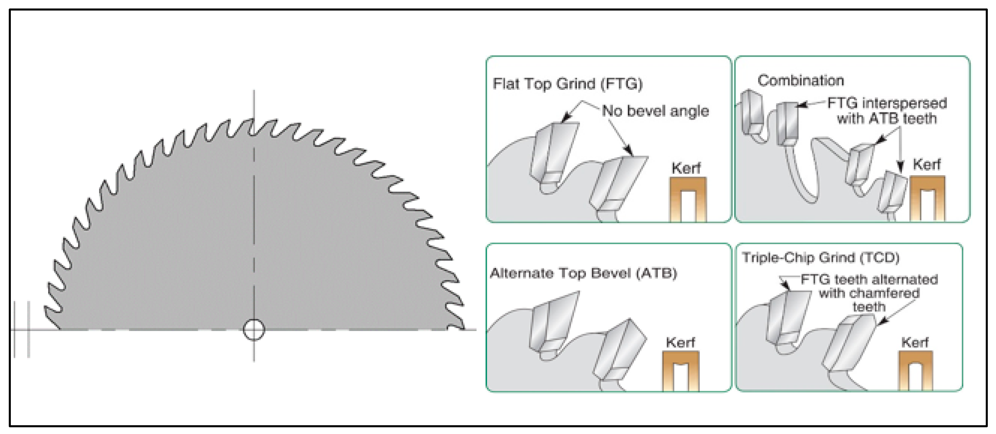
Figure 1.
Basic types of saw blades [31].
Figure 1.
Basic types of saw blades [31].
2. Materials and Methods
Experimental measurements were carried out in the premises of the Technical University in Zvolen, specifically in the workshops intended for research and development. The measurements were carried out with the help of a measuring device, which consists of two main mechanisms, the cutting and feeding mechanisms. The used tools of the main cutting mechanism, in which the value of the cutting speed was changed, were two types of saw blades of different construction (Figure 3 and Figure 4). The secondary feed mechanism consisted of a support driven by a threaded rod. This mechanism ensured that the workpiece was fed into the cut while changing the value of the feed rate. The division of the test prisms of two types of wood was done by transverse sawing, i.e. perpendicular to the direction of the grain of the workpiece.
The next step after obtaining the measured values was the calculation of the parameters needed to express the theoretical cutting force, which was subsequently compared with the real values of the experiment. Individual results of theoretical calculations of cutting force and actual values were recorded in the form of tables for better clarity.
In the selected CAD system, by defining the cutting forces converted to individual teeth in the cut, the 3D models of the saw blades were loaded when the corresponding cutting parameters were entered, and simulations were carried out. Their result was a picture of the tension on the saw blades, which were compared with each other.
2.1. Measuring device and its components
The implementation of the experiment, which consisted of the transverse division of two selected types of wood with saw blades of the given dimensions, was carried out using an experimental device, the individual components of which are described in Figure 2. The most demanding requirements for machine tools are accuracy and precision, which mainly depend on the static deformation and dynamic behavior of the machine tool under variable cutting forces [23,30].
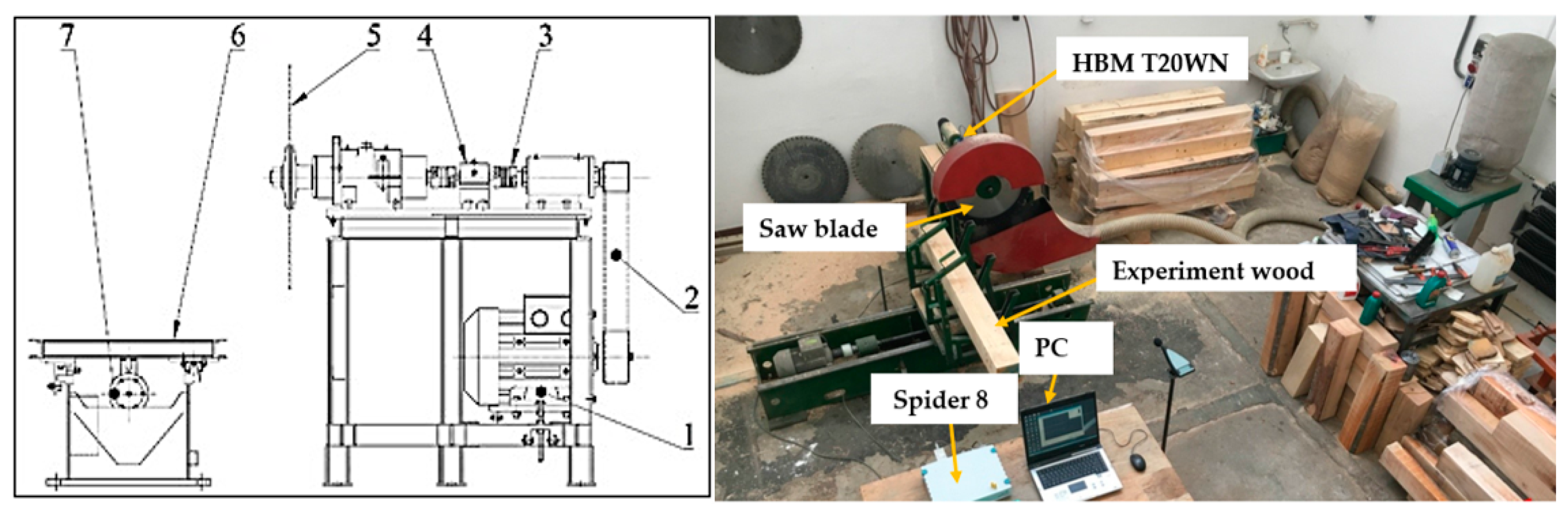
Figure 2.
Scheme of the experimental measuring device. 1 - electric motor of the cutting mechanism -7.5 kW, 2 - belt transmission, 3 - safety clutch Giflex GFLL, 4 - sensor of torque and revolutions HBM T20WN, 5 - saw blade, 6 - fixing sliding carriage, 7 - electromotor feeding mechanism 5.5 KW.
Figure 2.
Scheme of the experimental measuring device. 1 - electric motor of the cutting mechanism -7.5 kW, 2 - belt transmission, 3 - safety clutch Giflex GFLL, 4 - sensor of torque and revolutions HBM T20WN, 5 - saw blade, 6 - fixing sliding carriage, 7 - electromotor feeding mechanism 5.5 KW.
The work table (Figure 2) contains a three-phase asynchronous electric motor (1) with a power of 7.5 kW. The torque is transmitted through the flat belt (2) and further through the bearing, safety clutch (3) GIFLEX GFLL – 28 input clutch of the torque sensor (4), torque sensor HBM T20WN, output clutch of the torque sensor, spindle for the saw blade ( 5). The processed material is held in the sliding part (6) by means of a lever mechanism, which ensures sufficient clamping. The advance of the workpiece is provided by an electric motor (7) with a power of 5.5 kW. The signal from the torque sensor (4) is sent via cables to the Conmes Spider 8 measuring center, which is connected to a PC. The measured data is saved on the HDD of the computer (PC). Using the HBM T20WN torque sensor, we can also record the revolutions of the saw blade.
2.2. Preparation of wood samples
In the experiment, samples of Norway spruce with dimensions of 150 x 150 x 1500 mm were used. Individual samples were sawn from fresh spruce logs with dimensions of 3000 mm. The log was shortened using a chainsaw to half its length, which was transported using a transport cart to the MEMBER HTŽ 1000 horizontal band saw, where the log was processed into samples of the required dimensions.
2.3. Moisture of the samples
Moisture was measured using the gravimetric method, which consists in determining the weight of wet and dried wood by weighing. 2 samples with dimensions of 50 x 50 x 20 mm were taken from the trees intended for the experiment. These samples were initially weighed to establish a reference weight value. Subsequently, the samples were dried using a MEMMERT UF 30 plus dryer, which was set to 110℃. The samples were dried for 15 minutes. After this time, the samples were removed and reweighed [22].
2.4. Tools used
In the experimental measurement, two types of saw blades from the manufacturer Pilana Tools were used, which underwent surface treatment by coating. A tool steel saw blade (Figure 6) and a saw blade with SK blades (Figure 7) were used for the experiment. Table 1 lists the parameters of individual discs.

Table 1.
Basic parameters of used saw blades.
| Type of saw blade | Disc diameter D (mm) | Face angle φ (°) | Back angle α (°) | Disc body thickness b (mm) | Tooth width bD (mm) | Number of teeth from (-) |
|---|---|---|---|---|---|---|
| Tool steel disc HSS | 600 | 20 | 15 | 3.5 | 3.5 | 56 |
| Roll with SK slices | 600 | 20 | 15 | 3.5 | 5.2 | 54 |
Saw blade Figure 3 HSS is made of carbon tool steel 75Cr1(DIN 1.2003). The hardness of the coated saw blade was measured with a Rockvell hardness tester, where the hardness value reached 43 HRC. The disc is intended for longitudinal and transverse cutting of soft and hard wood. It has 56 teeth, which are alternately spaced - 1/3 of the thickness of the body of the saw blade on each side [12].
The blade is characterized by SK slices in the shape of ATB, which are soldered to the body of the saw blade. The hardness of SK wafers after coating reached a value of 43 HRC when measured on a Rockvell hardness tester. The disc has 54 alternating teeth, equipped with a chip limiter as well as expansion holes ending in a circular hole. Dilation grooves are designed in such a way as to prevent deformations of the disc under the action of centrifugal forces and heating by friction (workpiece - disc), which results in a high-quality cut with low noise of the tool [12].
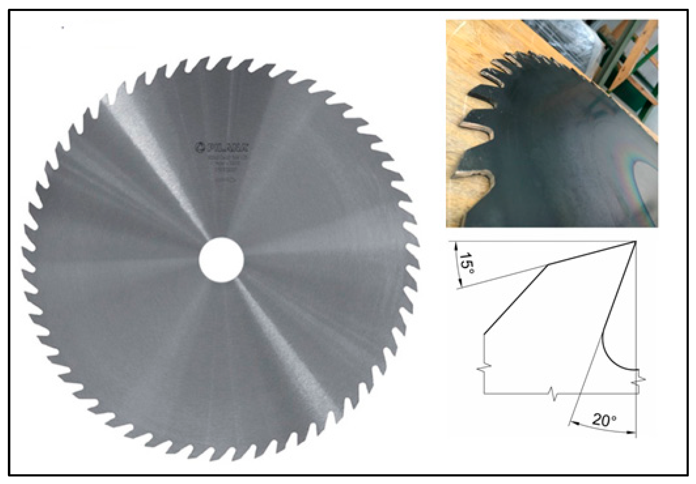
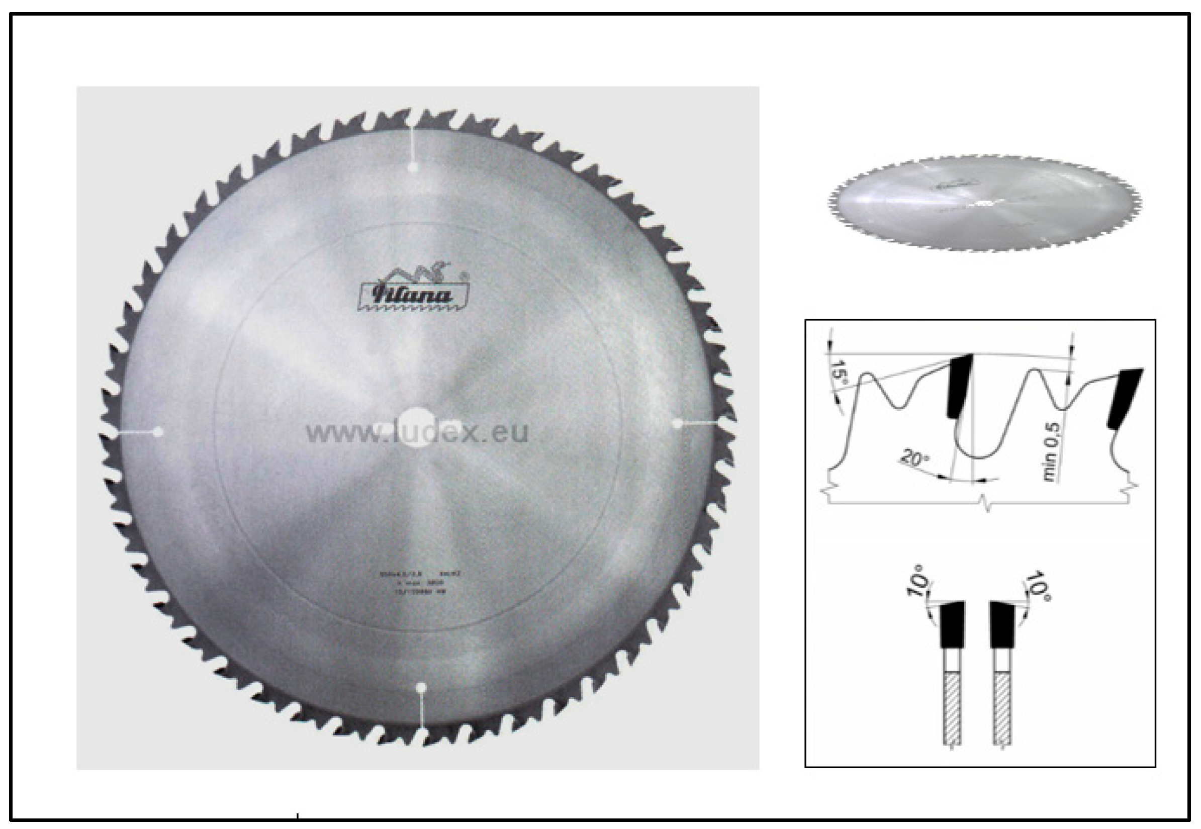
Figure 3.
Saw blade made of tool steel DIN 1.2003 – HSS.
Figure 4.
Saw blade with SK blades in the shape of ATB (Alternate Top Bevel).
2.5. Experimental measurement
Individual measurements were made at a cutting speed of 60, 70 and 80 m.s-1 and a feed speed of 6, 8, 10 and 12 m.min-1. The first step was to clamp the saw blade with SK blades on the shaft of the cutting mechanism. The disc was clamped between two flanges, which were secured by means of a lock washer and a nut. Subsequently, a spruce prism was inserted into the sliding support, the position of which was determined using hand clamps equipped with compression springs. After clamping the tool and the workpiece, a cutting speed of 60 m.s-1 and a feed speed of 6 m.min-1 were set on the frequency converter, and six measurements were made. Using the torque sensor, the values were recorded at the entire measurement, from which the five highest torque values were selected for each measurement, from which the average was calculated. Six measurements were then averaged and this value was later converted to cutting force for a given cutting speed and feed rate. Realization experimental measurements were made on both types of wood for all feeds, the frequency of the cutting speed of the saw blade was increased to a value of 70 m.s-1 and the procedure was repeated. Ending measuring at the highest cutting frequency and feed rate, the saw blade was replaced and measured again according to the procedure mentioned above. In addition, the effects of geometrical parameters, such as saw blade thickness and clamp diameter, on natural frequencies are also investigated using finite element analysis [24,25].
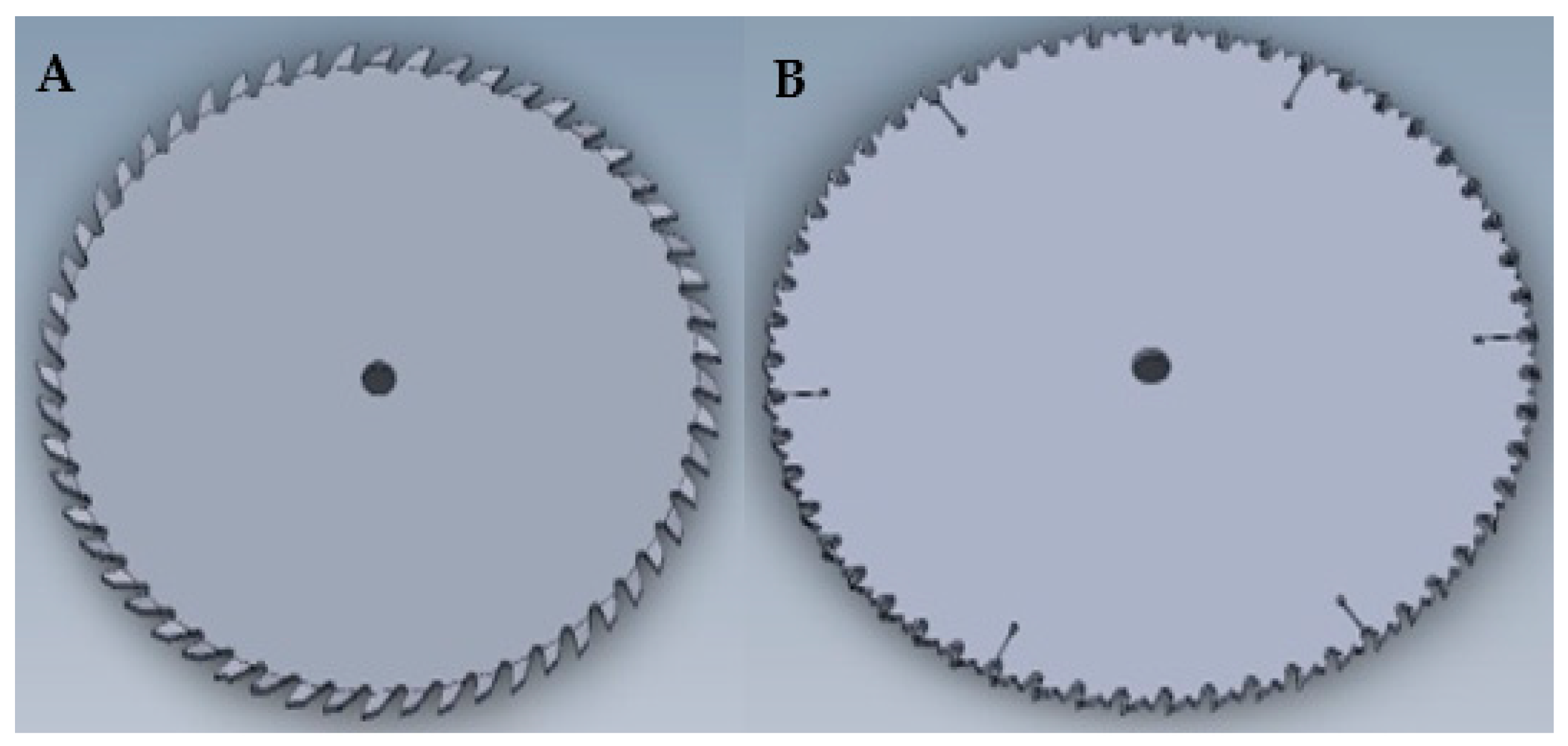
Figure 5.
Saw blade A- HSS and B – SK.
2.6. Calculation of cutting forces on individual teeth of the saw blade in the cut
From the performed calculations, it is clear that both saw blades have a maximum of 7 teeth in the engagement. The fact is that the first tooth in the cut takes the smallest chip and the last tooth the largest chip, which means that the individual teeth in the cut are not loaded with the same cutting force [17,18].
The cutting parameters of saw blades play a decisive role in the process of cutting wood, they directly affect the quality of the machined surface and the service life of the tool [21]. Unlike metal, plastic, or aluminum, wood tends to be heterogeneous and anisotropic. In fact, wood has three main directions: longitudinal, radial and tangential, which affects the partial results of experimental measurements [27]. The stress analysis was simulated for the cutting conditions vc = 80 m.s-1 and vf = 12 m.min-1, which represents the values of the calculation of the cutting force per unit area of the cut. The angles of the individual teeth in the engagement were also determined, which can be seen in Figure 6., which also confirms that the number of teeth in the engagement obtained by calculation coincides with reality. Based on the previous values, it is possible to calculate the thickness of the chips removed by the individual teeth of the saw blade.
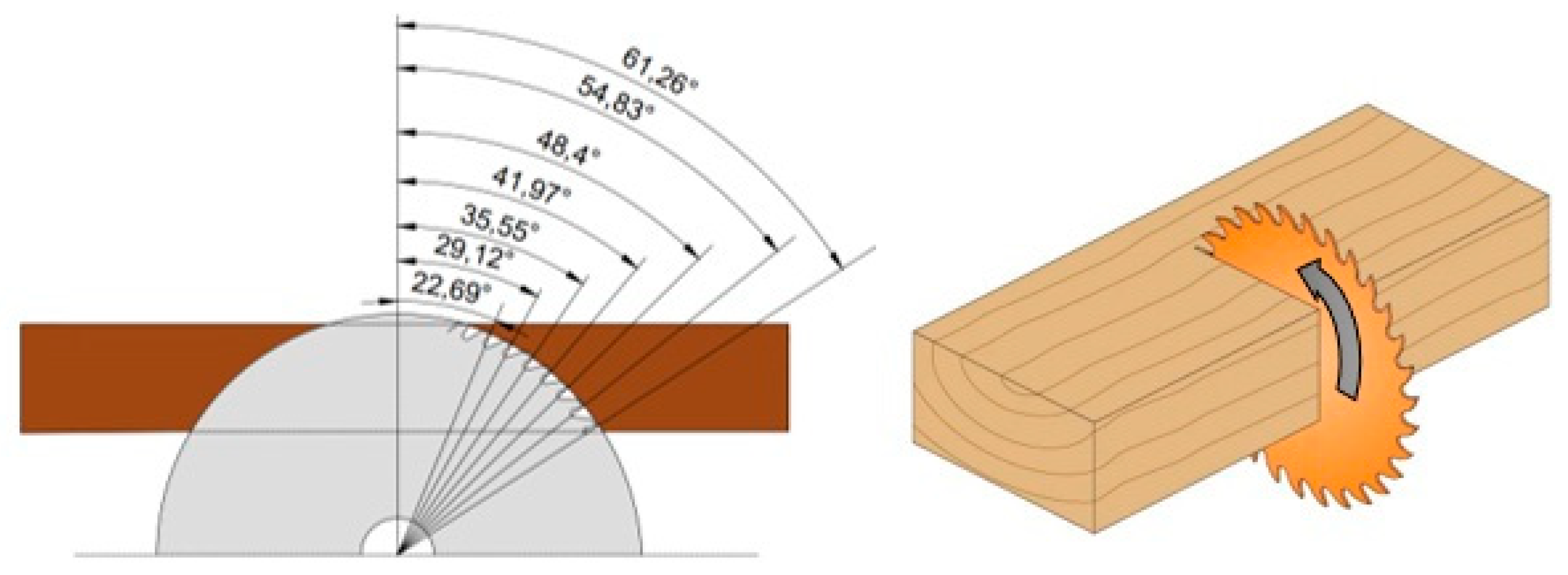
Figure 6.
Angles φ belonging to the individual teeth in the engagement for the HSS wheel.
Cutting force per unit of cutting area:
Cutting force acting on one tooth in engagement:
Cutting power:
where:
- kc- cutting force per unit of cut area [N.mm-2],
- bD- width of chip removed [mm],
- e- cutting height [mm],
- vf- feed rate [m.min-1],
- vc- cutting speed [m.s-1].
3. Results and Discussion
The stress analysis is carried out using the CAD system PTC Creo Parametric 5.0. Important data for performing the analysis are the values of the cutting forces Fc acting on the individual teeth of the saw blade in the engagement, which are presented in the previous chapter. Using the size and direction of the cutting forces together with the boundary conditions, it was possible to implement a simulation, in the evaluation of which the program includes the action of the gravitational force, as well as the size of the centrifugal force for the specified cutting conditions. The results give an approximate idea of how big stresses can act on individual parts of the saw blade from the point of view of theory and practice [13,14,15,16].
From the calculations presented in the post, it is clear that both saw blades have a maximum of 7 teeth in engagement. The fact is that the first tooth in the cut takes the smallest chip and the last tooth the largest chip, which means that the individual teeth in the cut are not loaded with the same cutting force.
The individual angles of the teeth in the engagement can be defined according to Figure 6, which also confirms that the number of teeth in the engagement obtained by calculation coincides with reality. Based on the previous values, it was possible to calculate the thickness of the chips removed by the individual teeth of the saw blade [19].
The cutting forces were placed at the highest points of the saw teeth because these parts of the teeth penetrate the workpiece first and are therefore the most stressed. The initial penetration of the highest point of the tooth into the workpiece is manifested by the area of a triangle, while this area is constantly increasing and changing, as a result of which the tooth penetrates deeper into the material. For tool steel discs, the entire edge of the saw tooth was loaded, because when placing the cutting forces at the highest points of the teeth, the hardware was not able to evaluate the number of mash grid points in the small area of the triangle and thus was not able to perform the simulation. The distribution of cutting forces on individual teeth is evident from Figure 8 and Figure 9.
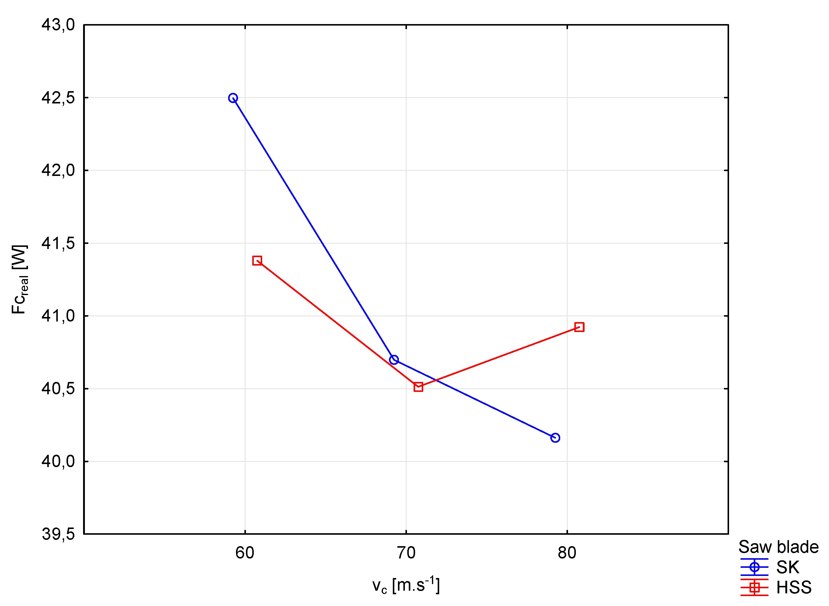
Table 1.
Results Measurements from the Statistica program.
| Cutting force | No of.Measurements | Average | The minimum | Maximum | Sm. departure |
| Fc-real [W] | 60 | 41028 | 38430 | 43760 | 1.311300 |
Figure 6.
Process of experimental measurement of HSS and SK saw blades.
Figure 7 shows the course of the cutting force (Fc) evaluated from the measured cutting power depending on the cutting speed (vc) and type the saw blade used. In the case of a disc with SK plates, there is a significant decrease in cutting force with increasing cutting speed. With the HSS blade, similar to the SK, there is a visible decrease caused by a change in the cutting speed of 70 m.s-1, but with a further increase in the cutting speed, the cutting force increases. The results of the stress analysis (Figure 10, Figure 11, Figure 12 and Figure 13) show that the greatest stresses are concentrated at the highest point of the cutting edge of the saw teeth in the engagement. The cutting force at this location by saw blade HSS represented Fc values from (3.43 - 7.79N) per tooth and by SK (Fc) values from (3,67 – 8,39N). The specific values of the forces on the teeth of the saw blade in engagement are shown in Table 2 and Table 3. The cutting force acted on the surface of the cutting edge uniformly, thus it was able to simulate real stresses. The model of the tested teeth of the saw blade in the loaded state is shown in Figure 8.
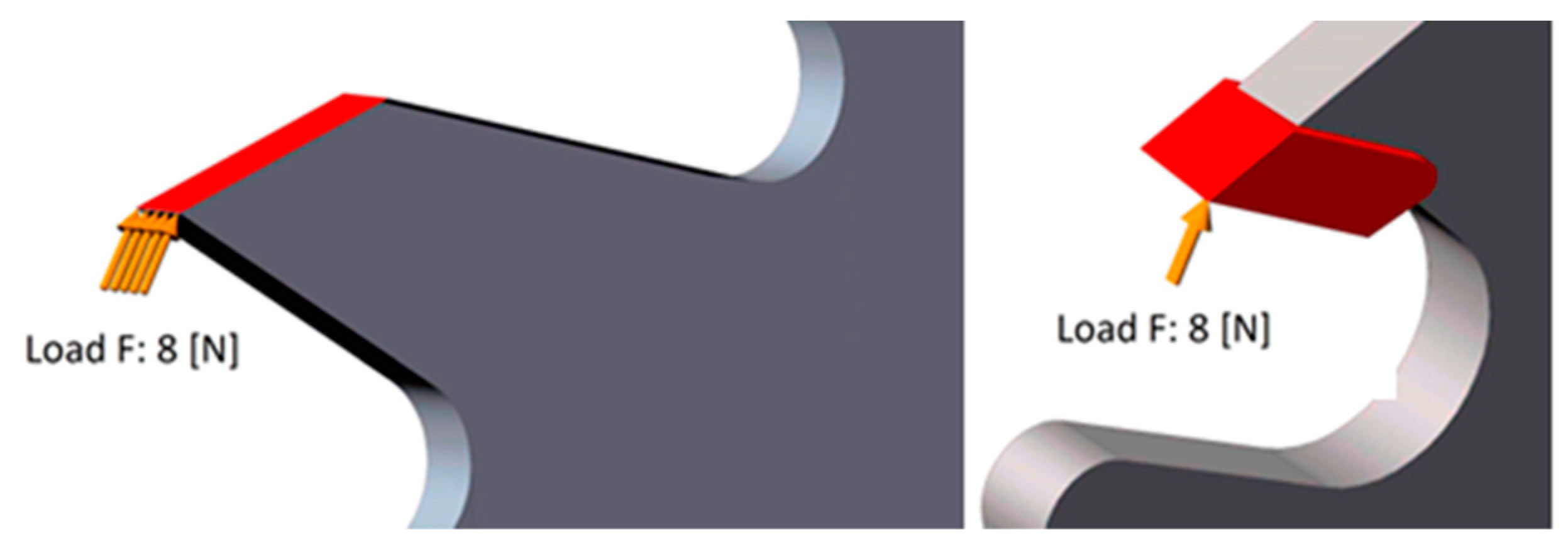
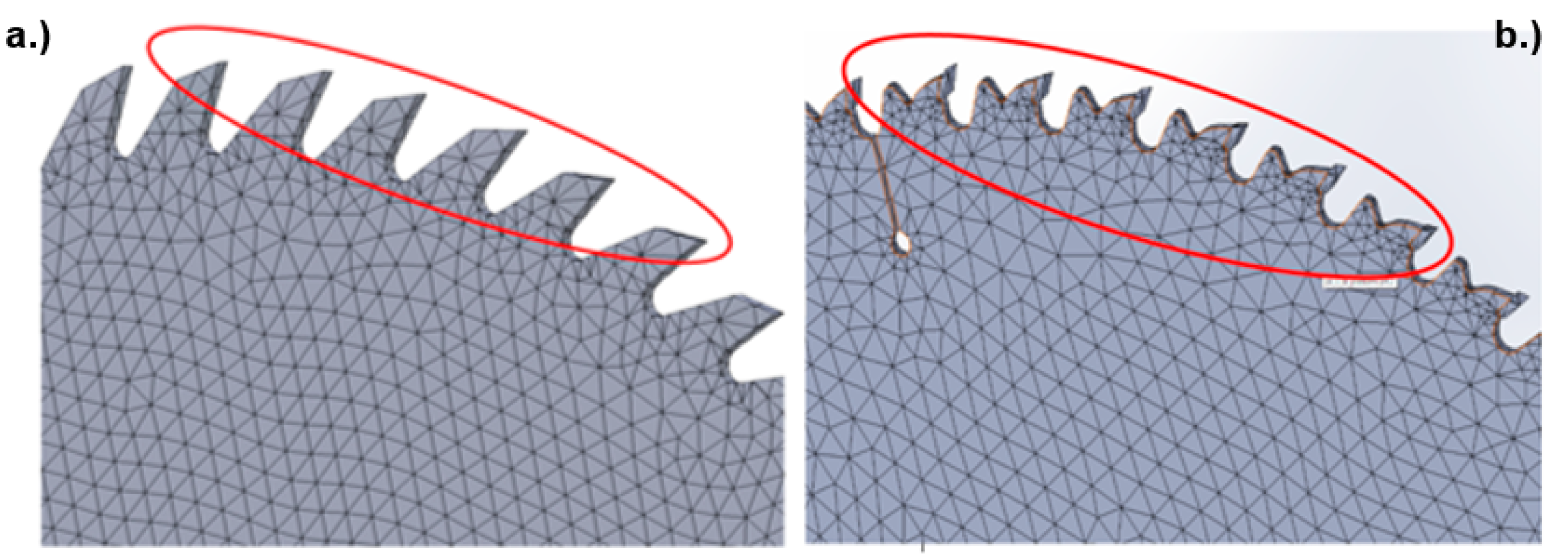
Table 2.
Measured values of the cutting force acting on the teeth of the saw blade.
| Type of saw blade | HSS | SK |
|---|---|---|
| Wood | Spruce | Spruce |
| 3.43 | 3.67 | |
| 4.32 | 4.65 | |
| 5.16 | 5.57 | |
| 5.94 | 6.42 | |
| 6.64 | 7.18 | |
| 7.26 | 7.84 | |
| 7.79 | 8.39 |
Table 3.
Calculated values of the cutting force acting on individual teeth of the saw blade.
| Type of saw blade | HSS | SK |
|---|---|---|
| Wood | Spruce | Spruce |
| 4.33 | 6.94 | |
| 5.45 | 8.80 | |
| 6.51 | 10.54 | |
| 7.50 | 12.15 | |
| 8.38 | 13.58 | |
| 9.16 | 14.83 | |
| 9.83 | 15.87 |
Figure 7.
Load of individual teeth on the saw blade a.) HSS - b.) SK
Figure 8.
Networking of the saw blade with marking of loaded elements on the saw blade a.) HSS - b.) SK.
Figure 8.
Networking of the saw blade with marking of loaded elements on the saw blade a.) HSS - b.) SK.
By meshing the finite elements (Figure 9) through the "Mash" function, the locales on the cutting part of the knife were thickened with greater precision, and smaller gaps were created between the individual elements created by meshing for the so-called subsequent mathematical calculation. The mesh elements consisted of linear hexagonal elements consisting of 8 nodes and a parabolic tetrahedron, each containing 10 nodes. They consisted of a large number of vertices, where individual points could be connected and perform a more accurate stress analysis [3,28]. Moving away from this point, whether on the frontal, dorsal or lateral surface of the tooth, the stress values decreased significantly. At the same time, however, they appeared on both discs on the entire frontal and back part. This results from the fact that when the tooth enters the workpiece, its front part is stressed by tension and, conversely, the back part is stressed by pressure. Greater stresses were also recorded in the area of the clamping flanges, especially in the case of tool steel discs, which could be caused by the absorption of possible vibrations of the tool. The stresses in the area of the flanges were significantly lower in discs with SK plates. Tension concentrators for discs with SK were also dilatation grooves, which equalized the tension of the teeth in engagement. The simulation also shows that the body of the saw blades was stressed significantly less due to the maximum stresses. It is important to remember that compared to other parts of the saw blade, the stresses concentrated around the engaging teeth are still some of the greatest. Tension concentrators for discs with SK were also dilatation grooves, which equalized the tension of the teeth in engagement. The simulation also shows that the body of the saw blades was stressed significantly less due to the maximum stresses. It is important to remember that compared to other parts of the saw blade, the stresses concentrated around the engaging teeth are still some of the greatest. Tension concentrators for discs with SK were also dilatation grooves, which equalized the tension of the teeth in engagement. The simulation also shows that the body of the saw blades was stressed significantly less due to the maximum stresses. It is important to remember that compared to other parts of the saw blade, the stresses concentrated around the engaging teeth are still some of the greatest.

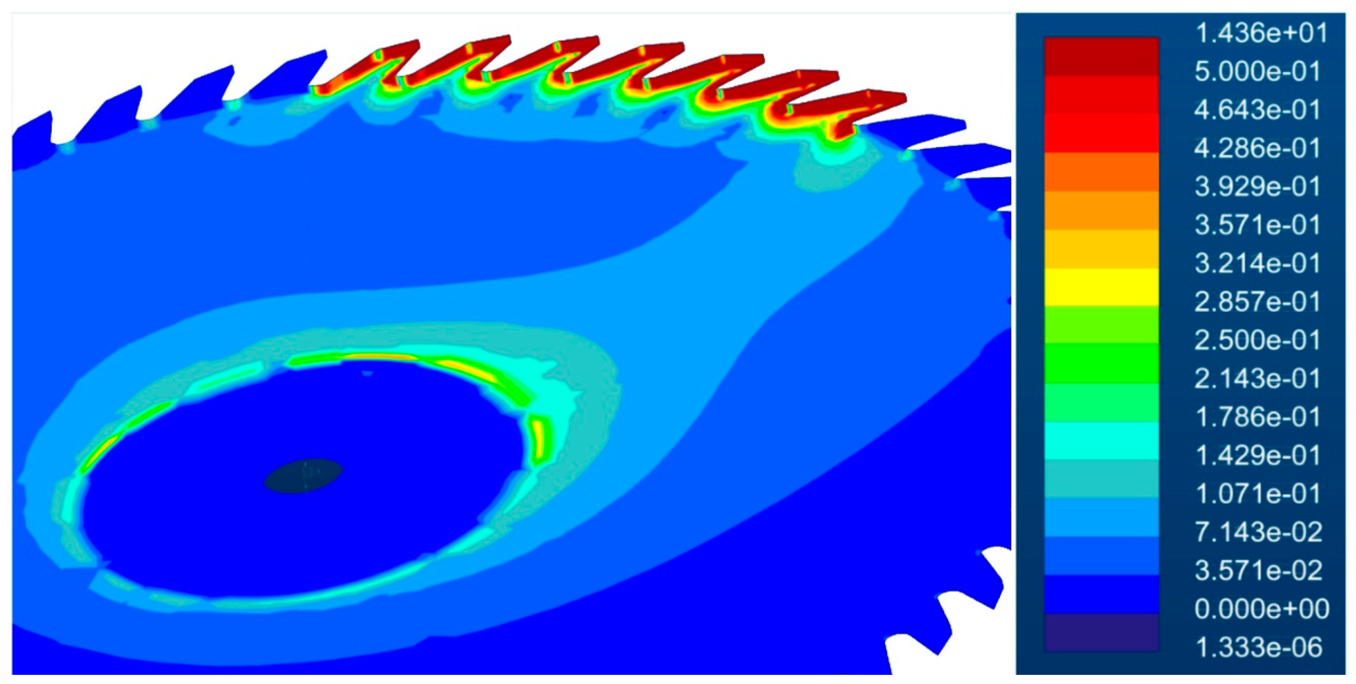
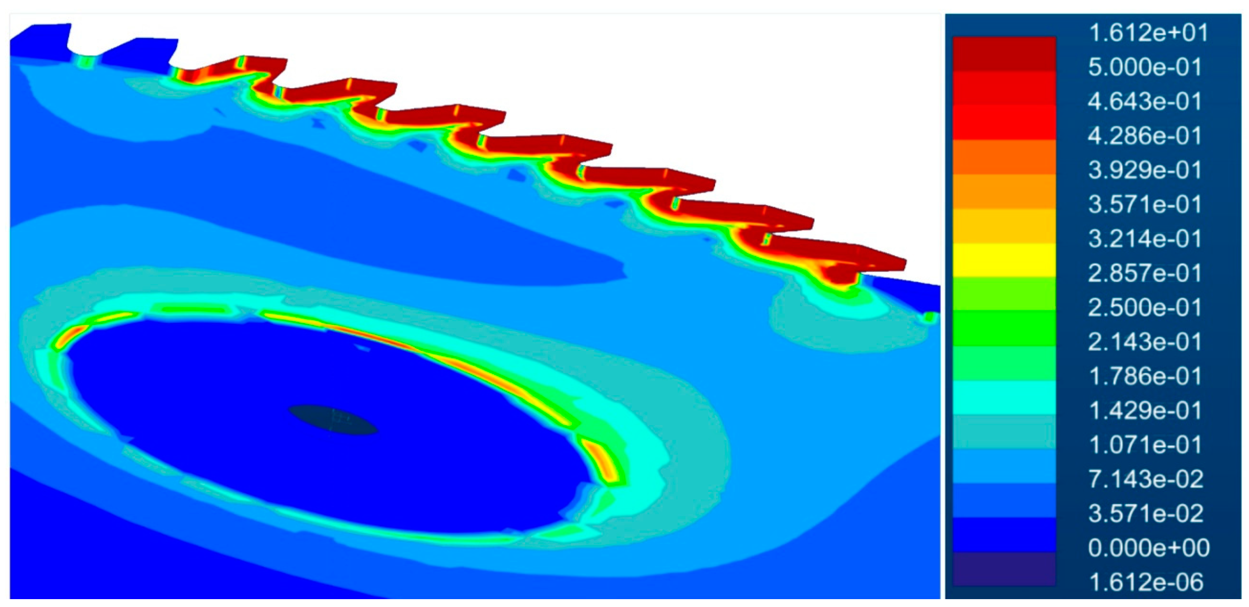
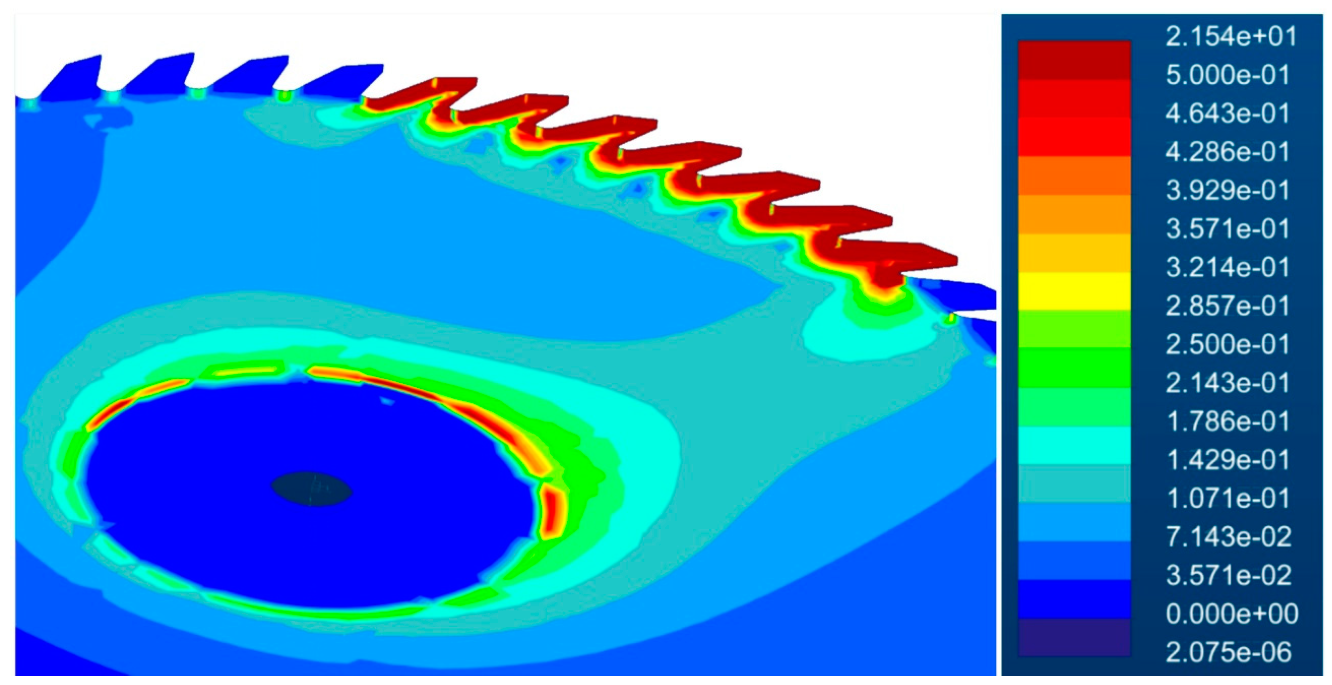
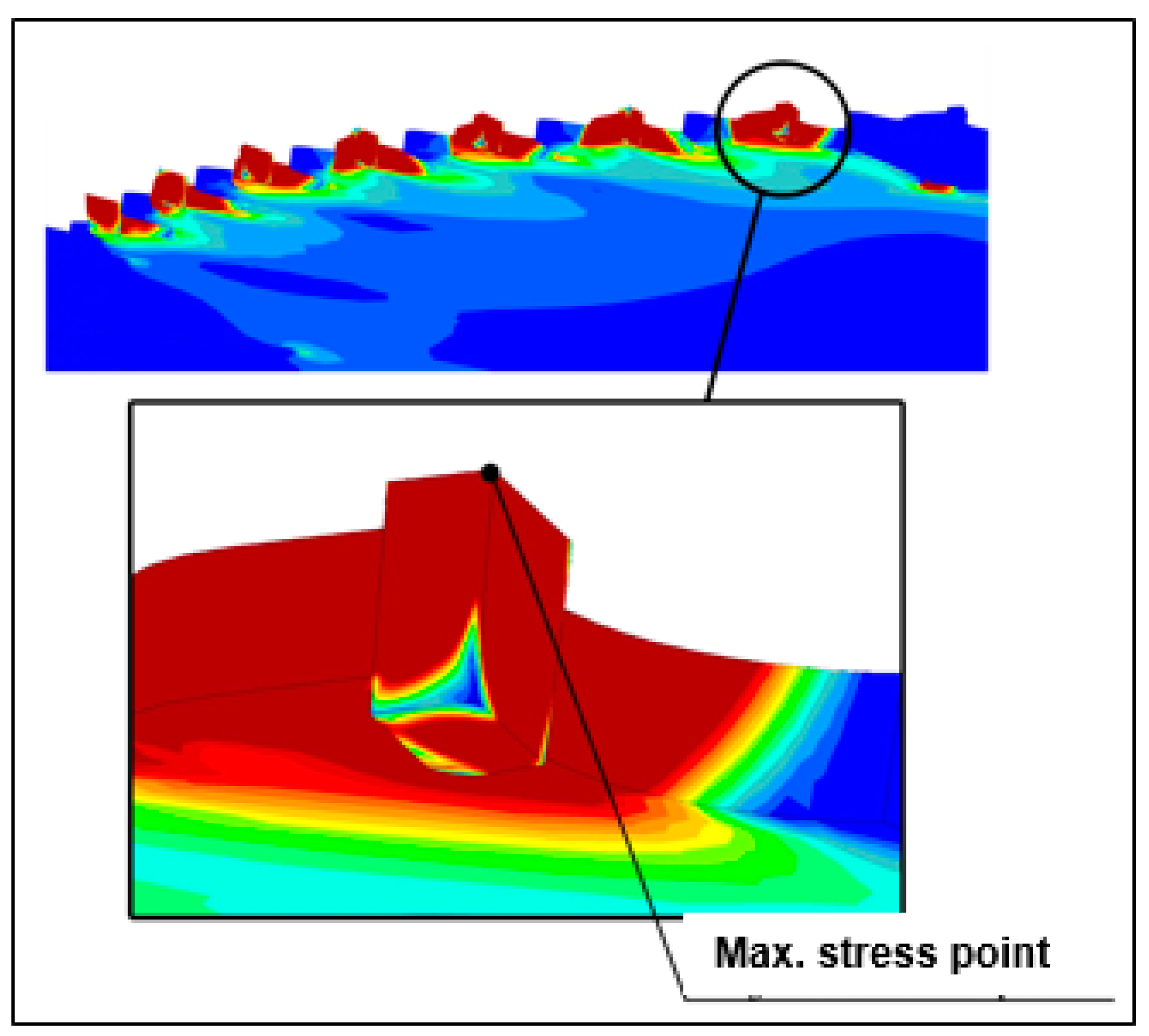
Figure 9.
Real stresses on the HSS saw blade when cutting spruce.
Figure 10.
Real stresses on the SK saw blade when cutting spruce.
Figure 11.
Theoretical calculation stresses on the HSS saw blade when cutting spruce.
Figure 11.
Theoretical calculation stresses on the SK saw blade when cutting spruce.
Figure 12.
The greatest stress on the last tooth in the shot.
In the narrow vicinity of these points, significantly lower stress values were found, ranging from 50 to 70 MPa. The maximum stress values for discs with SK can be justified by the fact that the program counted on a perfectly sharpened cutting tool, where the loading force was concentrated at the highest point of the tooth. In practice, this means that after a few shots of the disc into the workpiece, the cutting edges of the teeth would be slightly blunted, as a result of which the individual teeth in the shot would be loaded with significantly less tension than it turned out in the simulations. The simulation results also show that the stresses on the last tooth in engagement are greater than on the first tooth, with the first tooth taking the minimum chip thickness compared to the last tooth taking the maximum chip thickness. The simulation was carried out at the highest color gamut for 15 colors.
5. Conclusions
The results of the experiment show that the cutting conditions (cutting speed, feed speed) do not have a significant effect on the size of the cutting forces. The simulation results show that the highest stress values for both discs are concentrated on the tops of the cutting edges, which are the first to come into contact with the workpiece, while the maximum values are on the last tooth located in the engagement.
The theoretical and real stress values for HSS discs ranged from 14 to 22 MPa. Significantly larger differences were recorded for discs with SK, where the real values of the maximum stresses were around 14 MPa and the theoretical ones around 25 MPa. When cutting spruce with a disc with SK slices, the maximum values of the theoretical cutting forces were in the range of 76 to 94 N and the maximum values of the measured cutting forces were in the range of 40 to 44 N. In operating conditions, this would mean that if the tool had perfectly sharp cutting edges (which it does not actually have), after a few shots of the disc into the workpiece, they would be slightly blunted, which would cause considerably less stress on the individual teeth in the shot than the simulation shows. The simulation results show that the highest stress values for both discs are concentrated on the tops of the cutting edges, which are the first to come into contact with the workpiece, while the maximum values are on the last tooth located in the engagement. The values of stresses on the cutting edges for discs loaded with theoretical cutting force were greater compared to discs loaded with real cutting force.
Author Contributions
Conceptualization, J.M. and J.K.(Jozef Krilek); methodology, J.M., A.G., J.K. and J.K. (Jozef Krilek); software, J.M., J.K. (Jozef Krilek) and T.K; validation, J.M., T.K., M.A., J.K, and J.K. (Ján Kováč); formal analysis, J.M. and J.K. (Jozef Krilek); investigation, J.M and J.K. (Ján Kováč); resources, J.K.; data curation, T.K. and J.M.; writing—original draft preparation, J.M., J.K. and J.K. (Ján Kováč); writing—review and editing, J.K. and J.K. (Ján Kováč) and T.K.; visualization, J.M.; supervision, A.G., M.A., J.M. (Jan Mareček) and J.K. (Jozef Krilek); project administration, J.M, J.K. (Jozef Krilek) and Jan Mareček. All authors have read and agreed to the published version of the manuscript.
Funding
„This work was supported by the Slovak Research and Development Agency under the Contract no. APVV-21-0180.“ This work was prepared as part of the VEGA scientific grant project no. 1/0609/20 "Research of cutting tools in the processing of dendromass from agricultural and forestry production".
Acknowledgments
„This work was supported by the Slovak Research and Development Agency under the Contract no. APVV-21-0180.“ This work was prepared as part of the VEGA scientific grant project no. 1/0609/20 "Research of cutting tools in the processing of dendromass from agricultural and forestry production".
Conflicts of Interest
The authors declare no conflict of interest.
References
- Wedklov, IM (2015). "Increasing saw blade durability for cross-cutting wood, laser-treated blade," (http://tekhnosfera.com/povyshenie-iznosostoykosti-kruglyh-pil-dlya-poperechnoy-ra ilovki-drevesiny-metodom-lazernoy-termicheskoy-obrabotki-zubi), Accessed 20 September 2015. (Russian).
- Siklienka, M. , Kminiak, R., Šustek, J., and Jankech, A. (2017). Cutting and Processing Wood (Edition I), Technical University in Zvolen, Zvolen, Slovakia. (In Slovak).
- Krilek, J. , Ťavodová, M., Kováč, J., and Tichý, B. (2020). "Impact of irregular tooth pitch of circular saw blades on power for wood cross-cutting," Drvna Industrija: Zvanstveni Časopis za Pitanja Drvne Technologije 71(1), 3-11. [CrossRef]
- Kminiak, R. , andSiklienka, M. (2016). "Influence of the saw blade design on the cutting performance in the cross cutting of beech lumber on a circular saw blade with manual feed to cut," Chip and Chipless Woodworking Processes 10(1), 91-99. (In Slovak).
- Javorek, L., Kminiak, R., Vargovská, M., Csanády, E., Németh., S (2022). Feed Cutting Force Component in Up and Down Sawing of Pine, Drvna Industria - 73 (3) 279-288 (2022). [CrossRef]
- Lisičan, J. (1996). Theory and Technique of Wood Processing, Matcentrum, Zvolen, Slovakia. (In Slovak.
- Wang, X. , Yin, Z., and Li, Y. (2011) “The stress analysis of different circular saw structures during cutting,” Advanced Materials Research 228-229, 471-476. [CrossRef]
- Svoreň, J. Svoreň, J., Naščák, Ľ., Barcík, Š., Koleda, P., and Stehlík, Š. (2022) "Influence of circular saw blade design on reducing energy consumption of a circular saw in the cutting process, Appl. Sci. 2022, 12,1276. [CrossRef]
- Svoreň, J. (2002). Wood Processing Machines. Part I. (Edition I), Technical University in Zvolen, Zvolen, Slovakia. (In Slovak).
- Banski, A. (2000). "Maintenance of saw blades with sintered carbides," Wood Cutting Tools, Care and Safety at Work, Technical University in Zvolen, Zvolen, Slovakia, 76-85. (In Slovak).
- Siklienka, M. , Argay, F., and Kminiak, R. (2012). "Impact of saw blade geometry on surface quality in transverse sawing of grown wood," Chip and Chipless Woodworking Processes, Technical University in Zvolen, Zvolen, Slovakia, 325-333. (In Slovak).
- Uchneat, S. , Umberger, P., Stevenson, M., and McDougall, J. (2020) “Failure analysis of a fractured saw blade carbide tip,” Journal of Failure Analysis and Prevention 20(1), 2-8. [CrossRef]
- Sawmill. (2008). "Woodworking Tools," (˂http://www.pilana.cz/cz/ke-stazeni-pilove-kotouce-pasy-a-listy-na-rezani-dreva˃.).
- Melicherčík, J. , Krilek, J., and Harvánek P. (2020) "Simulation of stress and strain analysis on a delimbing knife with replaceable cutting edge," BioResources 15(2), 3799-3808. [CrossRef]
- Merhar, M. , Bučara, DG (2017) "The Influence of Radial Slots on Dynamic Stability of Thermally Stressed Circular Saw Blade, Drvna industrija, Vol. 68 No. 4, 2017. [CrossRef]
- Li, B. , and Zhang, Z. (2017) “Tensioning effect modeling of circular saw blade after multi-spot pressure tensioning process,” Advances in Mechanical Engineering 9(12), 1-9. [CrossRef]
- Li, B. , and Zhang, Z. (2019) “Analysis and optimization of the tensioning effect on a wood-cutting circular saw blade tensioned by multispot pressure,” Forest Products Journal 69(1), 61-69. [CrossRef]
- Orlowski, KA, and Ochrymiuk, T. (2017). “A newly-developed model for predicting cutting power during wood sawing with circular saw blades,” Maderas-Ciencia y Tecnologia 19(2), 149-162. [CrossRef]
- Orlowski, KA, Ochrymiuk, T., Hlasková, L., Chuchala, D., and Kopecký, Z. (2020) “Revisiting the estimation of cutting power with different energetic methods while sawing soft and hard woods on the circular sawing machine: and Central European case,” Wood Science and Technology 54(2), 457-477. [CrossRef]
- Wang, X. , and Zhang, Q. (2011) “The mechanical property analysis of circular saw blades under different rotational speeds,” Advanced Materials Research 145, 365-370. [CrossRef]
- Wen-Tung, Ch. , Chih-Hsien, S., Dong-Xie, G., Geo-Ry, T., and Fang-Jung, S. (2012). "Automated optical inspection for the runout tolerance of circular saw blades." The International Journal of Advanced Manufacturing Technology 66, 565-582. [CrossRef]
- Yang, X. , Deng, F., Deng, W., Xi, P., Tan, Ch., and Lu, X. (2019) "Optimization of designing on cutter parameters of PCD saw blades by simulation analysis," Journal of Superhard Materials 41(1), 60-68. [CrossRef]
- STN EN 13183-1 (2003). "Moisture content of lumber - Part 1: Determination by the kiln drying method. [Moisture content of a piece of sawn timber - Part 1: Determination by the oven dry method.” Slovak Office of Standards, Metrology and Testing, Bratislava, Slovakia. (In Slovak).
- Orlowski, KA, Dudek, P., Chuchala, D., Blacharski, W., and Przbylinski T. (2020) ”The design development of the sliding table saw towards improving its dynamic properties,, Appl. Sci. 2020, 10(20), 7386. [CrossRef]
- Li, S. , Wang, C., Zheng, L., Wang, Y., Xu, X., and Ding, F. (2016) “Dynamic stability of cemented carbide circular saw blades for woodcutting,” Journal of Materials Processing Technology 238, 108-123. [CrossRef]
- Li, B. , Zhang, Z., Li, W., and Peng, X. (2015) “Model for tangential tensioning stress in the edge of circular saw blades tensioned by multi-spot pressure,” BioResources 10(2), 3798-3810. [CrossRef]
- Kováč, J. , Harvánek, P., Krilek, J., Kuvik, T., and Melicherčík, J. (2021) "Analysis of cutting conditions in the process of cross-cutting wood by circular saws," BioResources 16(1), 1029-1041. [CrossRef]
- Eyma, F., Méausoone, PJ, and Martin, P. (2004) “Strains and cutting forces involved in the solid wood rotating cutting process,” Journal of Materials Processing Technology 148(2), 220-225. [CrossRef]
- Bílek, O., and Baďurová, J. (2018) "FEM analysis of saw blade," IOP Conference Series: Materials Science and Engineering 448. [CrossRef]
- Mikleš, M. , Kováč, J., Helexa, M., Krilek, J., Kuvik, T., (2016) Device for measuring the cutting conditions of tools,, Number UV 8298,https://wbr.indprop.gov.sk/WebRegistre/UzitkovyVzor/Detail/101-2017.
- Woodcraft. Available online : https://www.woodcraft.com/media/W1siZiIsIjIwMjAvMTAvMjIvMTMvMjgvMzIvNzQ1L0Nob29zaW5nU2F3QmxhZGVzMTAuMjIucGRmIl1d/ChoosingSawBlades10.22.pdf?sha=71a93348876b0a34 (accessed on 15.5.2023).
Disclaimer/Publisher’s Note: The statements, opinions and data contained in all publications are solely those of the individual author(s) and contributor(s) and not of MDPI and/or the editor(s). MDPI and/or the editor(s) disclaim responsibility for any injury to people or property resulting from any ideas, methods, instructions or products referred to in the content. |
© 2023 by the authors. Licensee MDPI, Basel, Switzerland. This article is an open access article distributed under the terms and conditions of the Creative Commons Attribution (CC BY) license (http://creativecommons.org/licenses/by/4.0/).
Copyright: This open access article is published under a Creative Commons CC BY 4.0 license, which permit the free download, distribution, and reuse, provided that the author and preprint are cited in any reuse.


