
Submitted:
09 June 2023
Posted:
09 June 2023
You are already at the latest version
Abstract
Reducing the costs of repairing concrete structures damaged due to the appearance of cracks and reducing the number of people involved in the process of their repair is the subject of a multitude of experimental studies. Special emphasis should be placed on research involving industrial by-products, the disposal of which has a negative environmental impact, as is the case in the research presented in this paper. The basic idea was to prepare a mortar with added granulated blast furnace slag from Smederevo Steel Mill and then treat artificialy produced cracks with a Sporosarcina pasteurii DSM 33 suspension under the conditions of sterile demineralized and water from Danube river in order to simulate natural conditions. The results show a bio-stimulated healing efficiency of 32.02% in sterile demineralized water and 42.74% in Danube water already after 14 days. The SEM images clearly show calcium carbonate crystals as the main compound that has started to fill the crack, and the crystals are much more developed under the Danube water conditions. As a special type of research, microscopic images of cracks were classified into those with and without the presence of bacterial culture. By applying convolutional neural networks (ResNet 50), the classification success rate was 91.55%.
Keywords:
granulated blast furnace slag
; Sporosarcina pasteurii DSM 33
; bio-stimulated healing
; Danube water
; CNN model
1. Introduction
Concrete is formed by a mixture of cement, coarse and fine aggregate with water. Cement in this mixture, plays an essential role by connecting aggregates and filling the space between them [1]. No building can be imagined without the use of concrete, and for this reason, concrete is the most widely used building material. Good concrete properties are primarily reflected in extremely high compressive strength, market availability, pourability into various forms, etc., and price. However, despite its good properties, this material has high cracking sensitivity due to its limited tensile strength. For this reason, it is often combined with steel reinforcement, which allows it to bear certain tensile loads. However, steel reinforcement cannot prevent crack formation but can only limit crack width. Cracks that appear over time result from various environmental influences to which building structures are exposed. Various aggressive liquids and gases can penetrate the cement matrix through these cracks. In the worst-case scenario, when the steel reinforcement is exposed to environmental influences, it can corrode and get severely damaged at the crack site. Such severe damages of building structures require repair, which makes maintenance even more expensive. According to available data for Great Britain, the annual costs of maintenance and repair of building structures exceed 40 billion pounds, while the USA plans to invest about 4.59 billion dollars in the next three years for their repair [2,3,4,5]. In addition to the economic impact, this also raises the issue of environmental protection through the conservation of resources and waste problems. However, the occurrence of damage does not necessarily cause major problems. Even a tad saving in repairing cracks and damage to building structures makes a difference for the economy and ecology of every country, especially if performed without human intervention [6,7,8,9,10,11].
For more than fifty years, there has been the idea of finding new, smart cement-based materials that have the ability to increase self-healing properties of concrete. Self-healing materials should be cheap and should not affect the properties of concrete structures, and the most important thing is that they should be active for a long time, as cracks usually do not appear immediately after installation. These materials could, at least partially, if not completely, reduce the appearance of damage while maintaining the initial structure properties and prevent the formation of subsequent permanent cracks that would further weaken the building [3,4,5,6].
The basic concept of self-healing materials in construction is to restore concrete strength, porosity, workability and waterproofing [12]. Certainly, using building materials with self-healing properties would require more significant financial investments at the very beginning, but they would still bring savings over time [13].
The self-healing phenomenon is defined by the material’s ability to heal small cracks on its own without external human intervention [13,14].
Self-healing of concrete can be greatly contributed by the presence of certain mineral additives such as fly ash, blast furnace slag, silica fume, limestone powder, geomaterials, etc. which are added as additives, since they stimulate autogenous healing, especially in the later phase due to the slower pozzolanic reaction of non-hydrated binders [13,15]. In the presence of water, pozzolanic materials react with portlandite (Ca(OH)2), forming binding products, and calcium carbonate [15].
Granulated blast furnace slag and fly ash, as industrial by-products, are inexhaustible research topic as cement additives, and the reason for this is primarily their pozzolanic activity. In their cement matrix self-healing experiments, Li et al. (2020) only used granulated blast furnace slag in different mass ratios, with added crystalline admixtures. Their results showed that mortar with 10% granulated blast furnace slag and crystal additives demonstrated self-healing properties and that calcium carbonate was the product that healed the crack [16,17].
Moreover, calcium carbonate precipitation is a common natural phenomenon. In addition to being found in nature (earth crust, sea and fresh water), calcium carbonate is a raw material for obtaining cement, which makes it one of the most useful building materials. In addition to having a wide range of minerals, carbonates are known to be produced by certain microorganisms, especially bacteria, and due to their crack-filling efficiency, they are used as one of the significant external self-healing methods for cement materials. Metabolic activities in the bacterial self-healing process lead to carbonate production, when carbonate ions react with calcium ions from the material, resulting in calcium carbonate formation due to system oversaturation [18]. In this way, cracks and gaps created as a result of damage to concrete structure are filled. Introducing microorganisms into the self-healing process requires great care, since many factors affect their metabolic activity. For example, lack of sufficient moisture and high pH is destructive to the bacteria metabolic activity [1].
Since concrete structures are designed to last over 100 years, the bacteria should survive and remain active during that period in a highly alkaline environment. In their paper, Renée and Henk (2012) presented the conclusions of Jose-Luis and Aylin (1996) about bacterial viability over a long period and under different conditions. Based on extensive research, it was found that bacteria are produced from thick-walled spores. These spores are resistant to chemical and mechanical loads and can remain dormant for a very long time. When conditions are created in the form of a concrete structure crack with food and water present, the spores germinate and transform into active bacteria and their metabolic products can fill the free crack space [6,19].
Although they have attracted a lot of attention of researchers in recent years, only a small number of studies connect experimental research and conclusions with numerical simulations and modeling, whether classical or artificial intelligence methods (such as the formation of mathematical equations that describe the crack healing trend, crack healing effectiveness prediction based on crack dimensions, data classification based on the appearance of samples, etc.). This type of analytical support in the crack healing process can significantly help engineers in their work. Through the developed model, it is possible to obtain useful data that direct reduce costs of subsequent research, saving materials and time, all with the aim of solving the problem as best as possible [8,10,20,21].
In accordance with the above facts, this paper is an expansion of existing ideas and current considerations and analyzes the possibility of incorporating industrial waste materials into new types of cement. In addition, the mortar self-healing process supported by bacteria as a external fealing agent was monitored through precipitation under sterile demineralized and Danube water. To the best of our knowledge, no study has been conducted to investigate bio-stimulated healing phenomena under the natural river (Danube) water yet. In our work we use this water based on the fact that Danube river is the second-longest river in Europe.
Considering a set of recorded post-healing images, in conditions with and without bacterial culture, their classification was performed. For this purpose, a deep learning methodology was chosen, i.e. a technique based on convolutional neural networks, which, according to the available literature has not been applied so far for this type of research.
2. Materials and Methods
The materials used in this research include CEM I cement from Lafarge BFC d.o.o. Beočin Serbia, a member of Holcim Group (alite cement), granulated blast furnace slag from HBIS GROUP Serbia Iron & Steel d.o.o. Belgrade - Serbia (slag), standard three-fraction sand as aggregate, suspension of Sporosarcina pasteurii DSM 33 as a means for external healing of cracks of new cement mixtures, sterile demineralized water and Danube water.
2.1. Characterization of the initial slag sample
For preparation of new cement mixtures, slag sample was characterized in detail to select the optimal quantities of material for alite cement replacement. The slag characterization involved determining physical and chemical properties, using standard methods that included meaning granulometric composition, pH value, chemical composition, specific weight, X-ray diffraction analysis - XRD, and scanning electron microscopy - SEM. A more detailed description of these methodologies is given below.
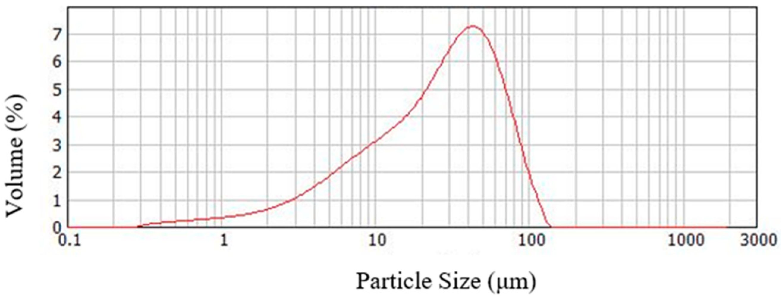
-Particle size distribution after micronization to 70% - 0.045 mm of the slag sample was confirmed by the laser light scattering method using Mastersizer Scirocco 2000 analyzer (Malvern Instruments, UK) [22].
-The chemical composition of the samples was presented through silicate analysis using the ICP-OES technique on a Varian 710-ES axial ICP-OES spectrometer [23].
-XRD analysis of the pulverized slag sample was performed on a PHILIPS PW 1710 diffractometer under the following conditions: copper anticathode radiation with a wavelength of CuKa = 1.5 4178 Å, graphite monochromator tube operating voltage: U = 40 kV, current strength: I = 30 mA, test range: 10 – 60º 2Q, step/time (qualitative tests): 0.02º/2 s [24].
SEM analysis confirmed the mineral composition of the slag sample. The equipment comprised:
- JEOL JSM 6460 LV scanning microscope with EDS device Oxford INCA - Digitized device, 3-of 4-nanometer resolution, magnification range 8 - 300,000 × and the possibility of working in low vacuum to environment levels,
- BAL-TEC, SCD 005 SPUTTER COATER – Vacuum device for preparing samples by vaporization with gold and carbon [25].
2.2. Characterization of the cement sample
CEM I is a commercial product, no detailed characterization of the sample was performed, but only chemical, setting time, compressive and flexural strength analyses.
-The chemical analysis methodology is described in the previous chapter.
-The cement mortars setting time was tested using Vicat apparatus according to the SRPS EN 196-3:2017. The test room temperature should be 20±2 °C, and the relative humidity should be at least 50% [26].
-Determination of flexural and compressive strength is described in SRPS EN 196-1:2017 [27].
2.3. Characterization of Danube water
Water from Danube river was tested using ion chromatography method. Ion chromatography is a method of chromatographic separation of ions in a solution using a solid ion exchange material-filled column and is ideal for determining very low concentrations of present ions. It is possible to simultaneously analyze a group of inorganic anions (fluorides, chlorides, nitrites, bromides, nitrates, phosphates and sulfates), and cations of alkaline and alkaline earth metals in water, as well as ammonium ions. This method is used for analyzing all types of water, and it is most widely applied in drinking water analysis [28].
2.4. Preparation and bio-stimulated healing mortar
Initial sample characterization was followed by the preparation of a new type of mortar and its characterization by examining the strengths, chemical composition and setting time.
The new mortar system was prepared with a 10% slag replacement fraction instead of alite cement using the method described in SRPS EN 196-1:2017. The sample prisms were of standard dimensions 40 x 40 x 160 mm and laboratory dimensions of 10×10×60 mm. Flexural and compressive strengths were tested after 2, 28 and 240 days of water curing on hydraulic presses by Tinius Olsen, working force up to 231 kN and VEB Thuringer Industriewerk Rauenstein (standard prisms), working force 0-5 kN and 25-50 kN (laboratory prisms). For this type of mortar, the setting time was also determined using Vicat apparatus, according to SRPS EN 196-3:2017. The mortar system composition is given in Table 1.

Table 1.
Mortar system composition.
| System/ composition | CEM I, g | Three-fraction sand, g | Granulated blast furnace slag, g | Water, ml |
|---|---|---|---|---|
| Az10 | 405 | 1350 | 45 | 225 |
* Legend: Az10 -CEM I with the addition of 10% slag.
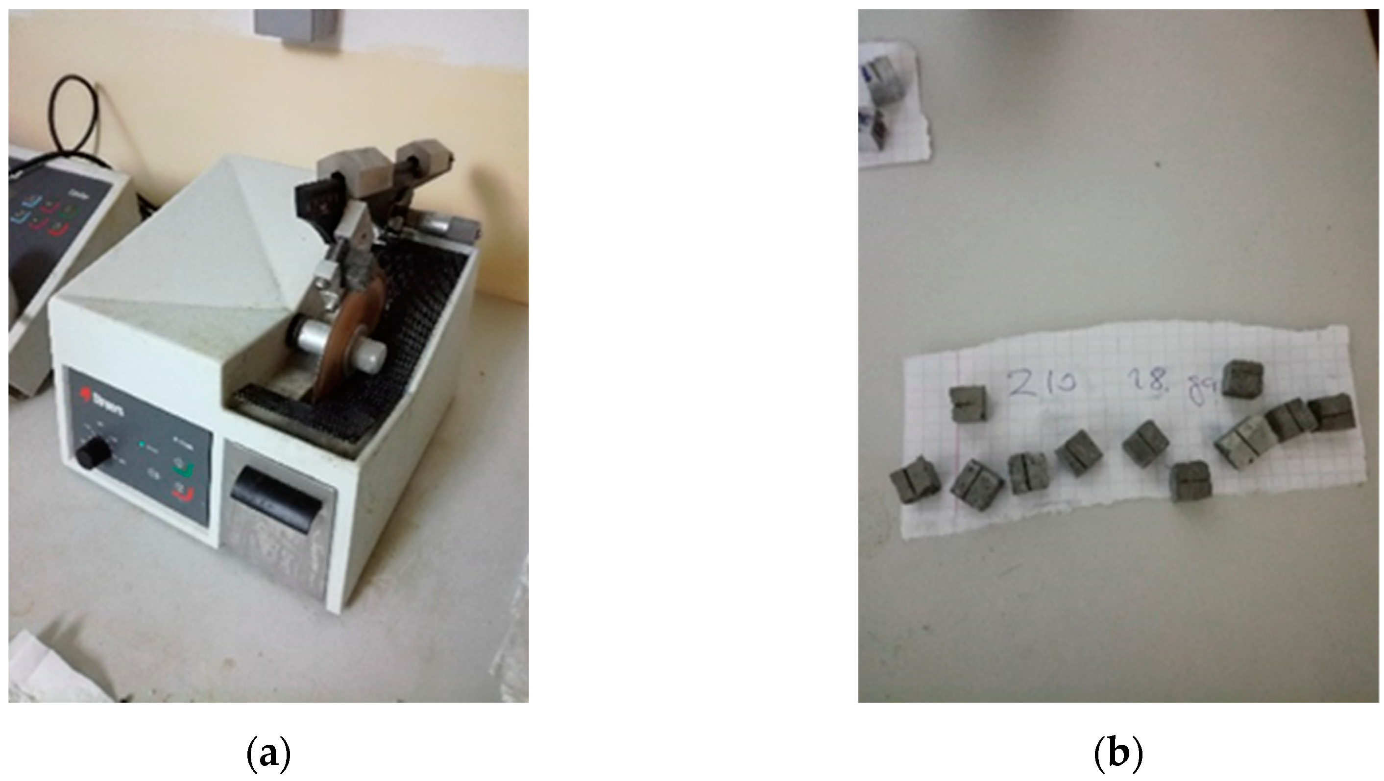
Determination of the strengths, setting time and chemical composition of the new mortar type was followed by the preparation of laboratory sample prisms for the bacterial bio-stimulated healing experiment. After preparation and water curing for 28 days, sample prisms of laboratory dimensions were cut with a diamond knife (Figure 1(a)) to 10x10 mm for easier manipulation, and a groove was artificially made on each sample as a real crack simulation (Figure 1(b)). In this way, enough samples were prepared for the needs of further experiments.
Figure 1.
Sample preparation: (a) applied laboratory equipment (diamond knife); (b) appearance of the prepared cracked sample.
Figure 1.
Sample preparation: (a) applied laboratory equipment (diamond knife); (b) appearance of the prepared cracked sample.
Considering that the selected bacterial strain S. pasteurii DSM 33 is highly sensitive to environmental conditions [29], the pH value had to be reduced to a value below 10, which was achieved by alternating immersion in distilled water and drying in a dryer for 2 hours each. After 20 washing cycles, the pH value was lowered from 14 to 9.
According to the established experiment program, 45 samples were singled out. The system was divided into five groups that were treated under different conditions, as shown in Table 2. Conditions 2 to 4 are control.
Table 2.
Conditions for systems.
| Groups | Conditions | Days |
|---|---|---|
| 1 | bacterial suspension, nutrient medium, sterile demineralized water | 7,14,28 |
| 2 | nutrient medium, sterile demineralized water | 7,14,28 |
| 3 | sterile demineralized water | 7,14,28 |
| 4 | Danube water | 7,14,28 |
| 5 | bacterial suspension, nutrient medium, Danube water | 7,14,28 |
The samples were placed in Petri dishes so that the crack was on the upper side of the sample, for easier healing agent application, with three repetitions in each group. Petri dishes with samples were sterilized for 1 h at 160 °C to eliminate any possibility of contamination. After sterilization, bacteria were applied in a laboratory at constant temperature of 25 °C, which favors bacterial growth.
The bacterial suspension was freshly prepared with sterile demineralized water. The nutrient medium was also freshly prepared from urea, NaHCO3, NH4Cl and sterile demineralized water.
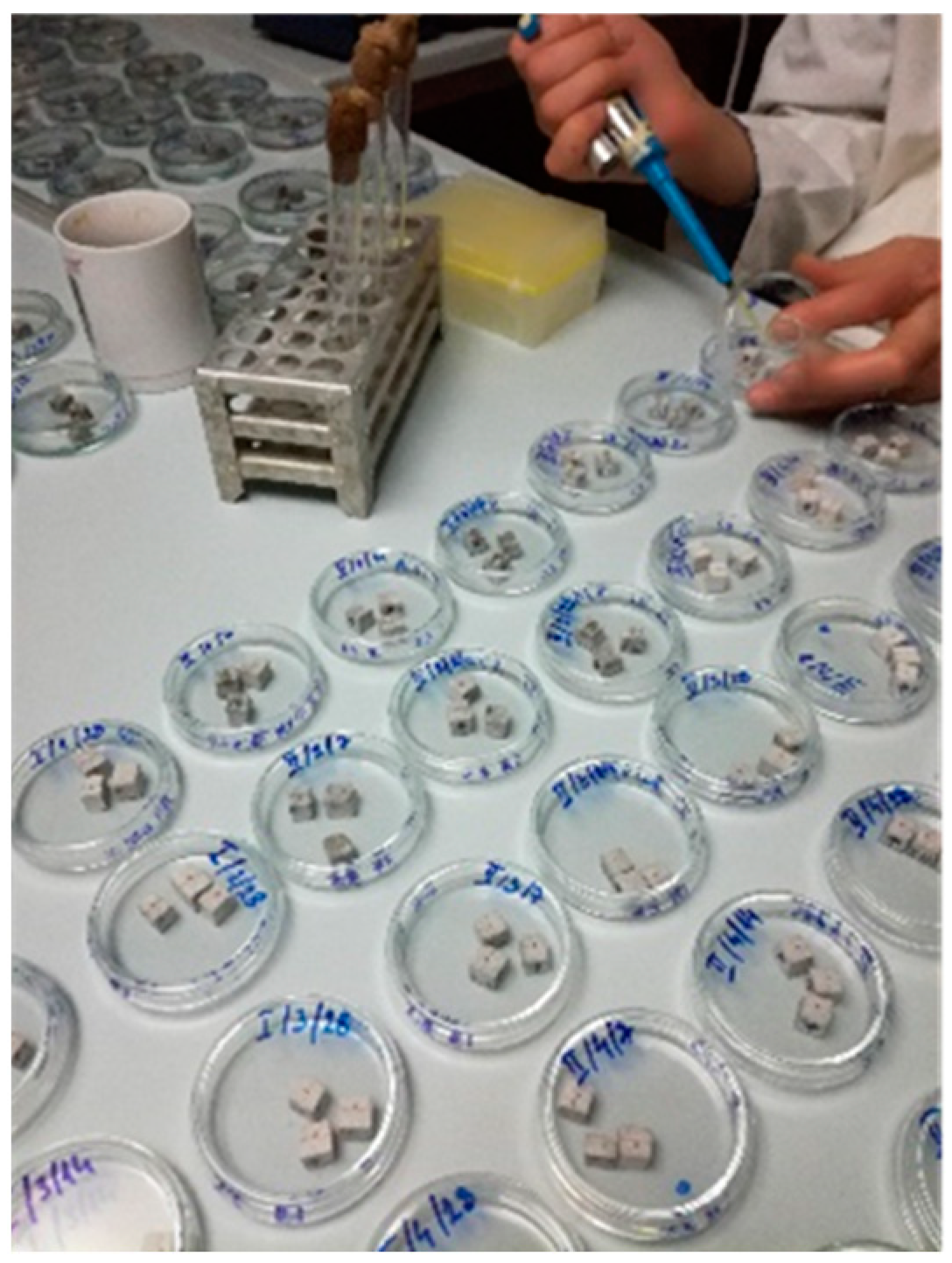
The nutrient medium and bacterial suspension were applied using a sterile pipette in the crack mid-line. Each sample of the first, second and fifth group was first given 50 μl of nutrient medium. After absorbing of nutrient medium, 50 μl of bacterial suspension was applied to each sample of the first and fifth group (Figure 2). Finally, the sterile demineralized water was added with a sterile pipette up to 1/3 of the sample height in the first, second and third group, while the fresh Danube water was added also up to 1/3 of the sample height in the fourth and fifth group (10 ml for smaller 6 cm diameter Petri dishes and 15 ml for larger 10 cm diameter Petri dishes). This amount of water was optimal for maintaining system humidity. After setting up the system, the Petri dishes with the samples were transferred to the Binder Climate Chamber KBWF 240. In the climate chamber, the systems were kept under controlled conditions of a temperature of 30 °C and humidity of 70% until testing.
The tests duration was 7, 14 and 28 days after the experiments setup. Non-destructive methods were selected to monitor changes in the bio-stimulated healing process, portable microscope imaging (described below – chapter 2.5) and SEM analysis, already described in chapter 2.1.
Figure 2.
Setup of bio-stimulated healing process.
2.5. Indentification of cracks
Cracks were indentified and non-destructively recorded using a portable Vitiny PRO10-3 microscope, which can operate at 10 to 30 x magnifications. The crack width was measured with the existing integrated microscope software.
2.6. Image classification
Image classification was performed in the MATLAB 2023A programming language using the convolutional neural networks methodology - ResNet 50, which has already been pretrained to extract features from digital images based on the rgb model.
Basic characteristics of the Convolutional neural networks (CNN) model
Convolutional neural networks are an extended model of multi-layer artificial neural networks, which were developed by adding a new type of layer used for image analysis (recognition and classification) [30].
Convolutional neural networks mimic the human visual system and may recognize complicated image features gradually. In the first layers of this network, simple attributes such as edges are detected. Based on what was detected in the previous, contours are recognized in the next layer. Contour detection is followed by the recognition of specific parts of the object so that the object can be classified in the final layer [31].
The principle behind convolutional neural networks is reflected in the direct input of image data in raw pixels since the image consists of pixels as the smallest element in a digital image (shown as the image having, for example, a width of 32, a height of 32 and a depth of 3). The first task of a convolutional neural network model is to transform the image it receives into a computer-understandable format. More precisely, the input data is represented as a two-dimensional pixel intensity matrix in the case of a single-channel image or as a multi-dimensional matrix in the case of a multi-channel image. So, in the input layer, the image data is entered into the network, and each entered pixel represents an input characteristic. Each pixel is described by its color as a color imaging system. There are many color spaces in which images exist and one of the most often used is RGD with three color channels: red, green and blue. Thus, for example, white is presented as (0,0,0), while black is (255,255,255) [32,33].
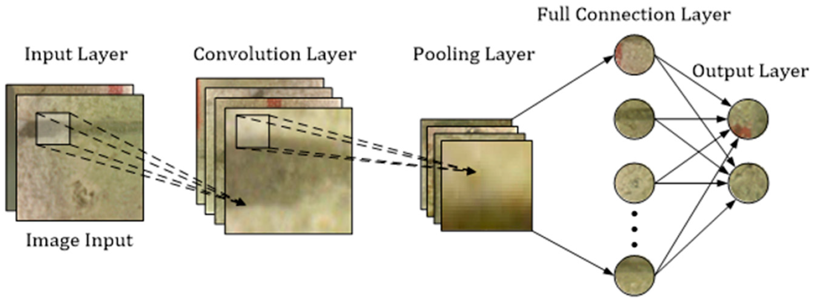
Data entry is followed by several alternating convolutional layers and pooling layers, which alternation reduces their dimensions. The end result is images very small in size, each representing one matrix. The matrix values are arranged into a vector that represents the input to the fully connected network [30,31,34,35]. A schematic representation of the basic convolutional neural network on the example of a cement prism crack image is shown in Figure 3.
Figure 3.
Simplified schematic representation of a convolutional neural network on the example of a crack image [adapted from 36].
Figure 3.
Simplified schematic representation of a convolutional neural network on the example of a crack image [adapted from 36].
Convolutional layer
The convolutional layer serves to extract the features of the input data using the filters located inside the convolutional layer. The input image size is larger than the filter size, but their depth is the same. Convolutional neural networks understand images in parts, so it is necessary to move the filter several times to complete the entire processing and obtain the value for the whole image [34].
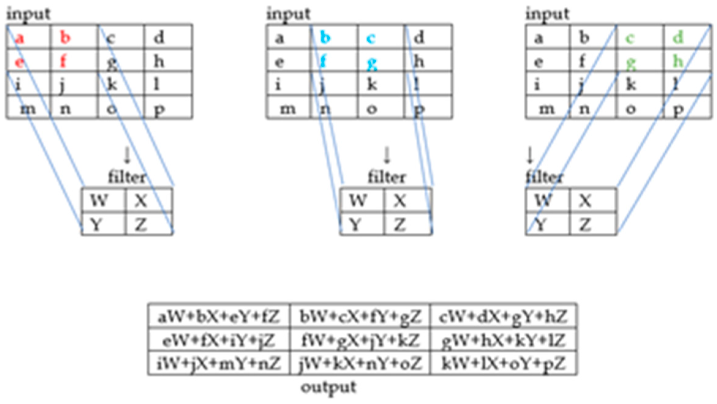
The filter window moving starts from the upper left corner and goes to the right by the same value. When we reach the edge, we move it downward, repeating the process. The filter is moved to multiply and add up each position of the starting pixel. That is, the filter scans subsamples of the initial images to detect localized features. The size of the subsample depends on the size of the filter. Each convolutional layer has a filter displayed as a two-dimensional matrix 3 × 3 (an example of m × n is shown in Figure 4) with an increment of 1. The output volume is obtained based on several filters that make up this layer and are grouped along the axis [34,35,36,37,38].
Figure 4.
Simplified schematic representation of the convolutional layer operation [adapted from 35].
Figure 4.
Simplified schematic representation of the convolutional layer operation [adapted from 35].
ReLu layer
The ReLu layer is introduced after the convolutional layer as an additional layer to increase image non-linearity and reduce calculation time. This layer serves to break the linearity imposed by passing the image through the convolutional layer [34,35].
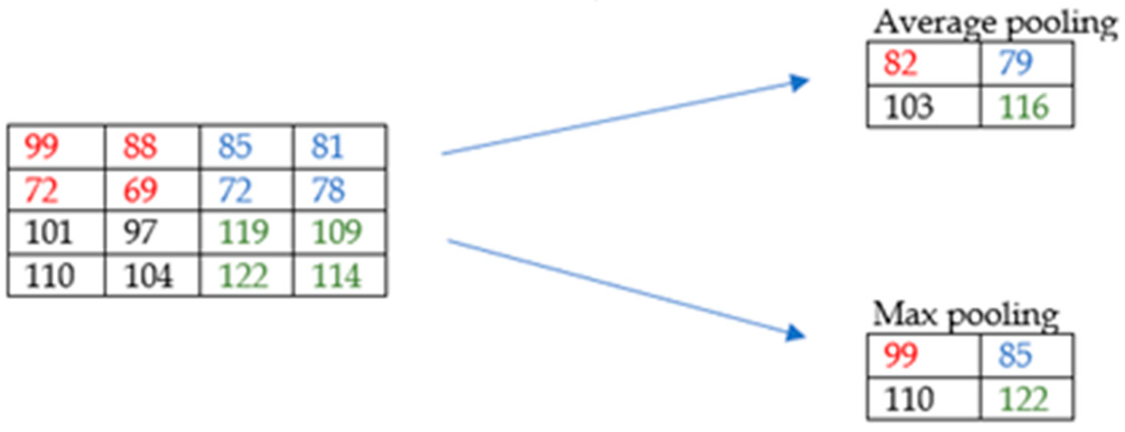
Pooling layer
The convolutional layer is followed by the pooling layer, in which the data dimension is reduced. This layer also has filters, but they have no weight here, unlike in the convolutional layer. Here, the role of the filter is to select the pixel that is within the dimensions covered by this layer in a given way. The maximum is often used as it works better in practice, although medium values are also acceptable (Figure 5). The pooling layer reduces the dimension of the feature maps while retaining the most important sample information. In this way, excessive overlaps are prevented. For maximum pooling, a 2 × 2 matrix is adopted. After pooling, the image feature map is aligned in one column, resulting in a vector. The long vector obtained in this way serves as the input to the artificial neural network, which is also the final step. An artificial neural network consists of an input, output and fully connected layer (network) [36,37,39].
Figure 5.
Simplified representation of the pooling layer operation [35].
Figure 5.
Simplified representation of the pooling layer operation [35].
The purpose of the convolutional neural network is to combine features from the input data to form a wide range of attributes in image classification [31].
Validation success can also be shown computationally through a precision expression adapted from[40]:
wherein:
TP – True Positive
FP – False Negative
TN – True Negative
FN – False Negative
F1-score and accuracy are used to precisely assess model performance, where F1-score takes into account precision and recall, and is calculated for both classes while accuracy represents the proportion of correct recognition of the entire sample.
3. Results and Discussion
3.1. Physical - chemical characteristics of slag
By control particle distribution check in the microsizer, 72.15% of the -0.045 mm size class was found for the slag sample after crushing, which corresponds to the standard requirements and can be used for mortar preparation. The results are shown in Figure 6.
Figure 6.
Particle size distribution in the slag sample graph.
The chemical composition is given in Figure 7.
Figure 7.
Chemical composition of the slag sample.
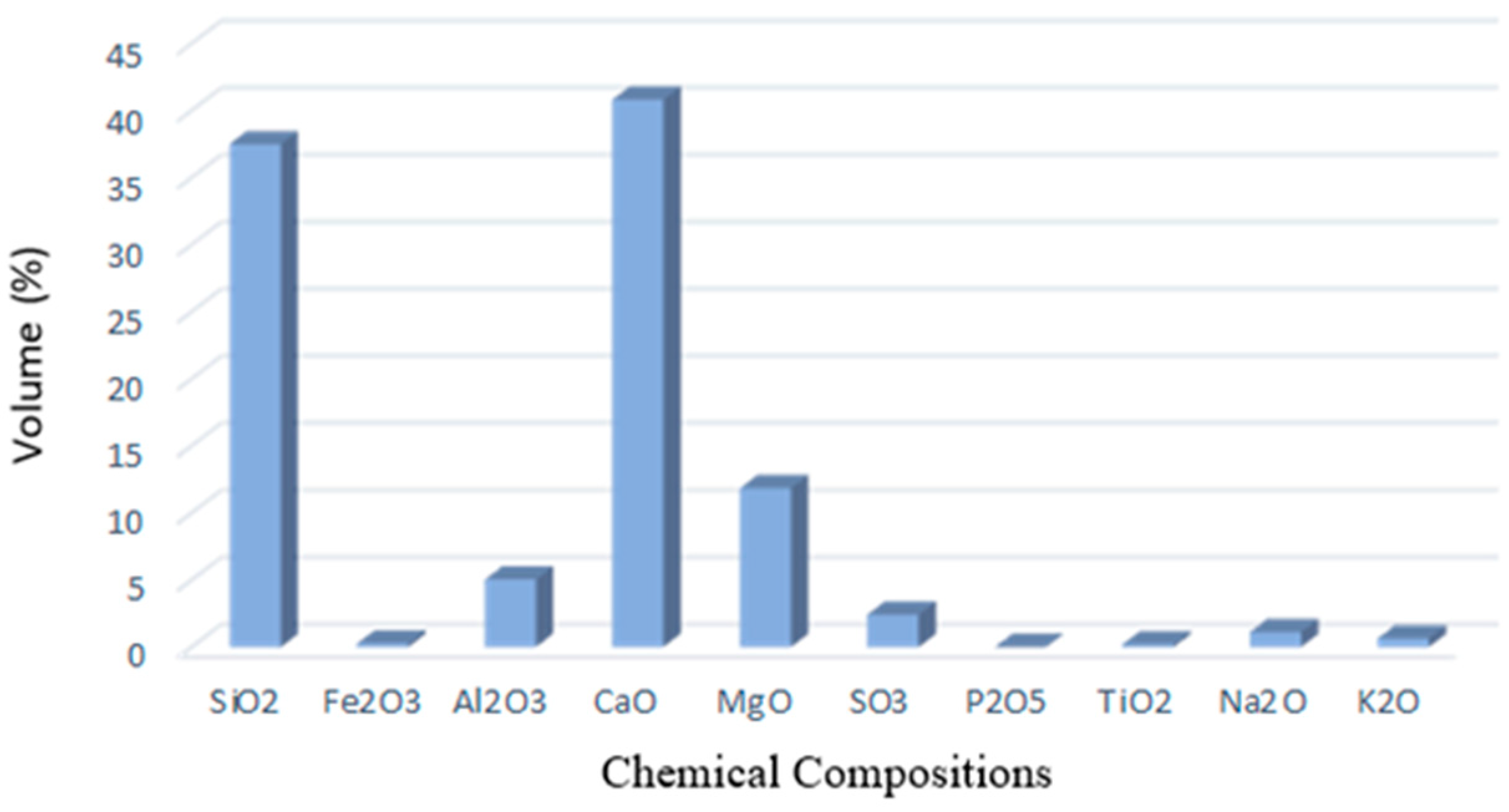
The slag sample is dominated by the contents of SiO2 and CaO, which affects their chemical activity and volume constancy. The alkali content is low, which is advantageous as their presence is undesirable in cement production. The share of MgO in the slag is increased compared to the allowed 5%. A higher quantity of MgO can affect, in addition to volume instability, the appearance of cracks [41] in mixtures with cement, which should be paid special attention to in experimental work. The measured slag pH value is 8.
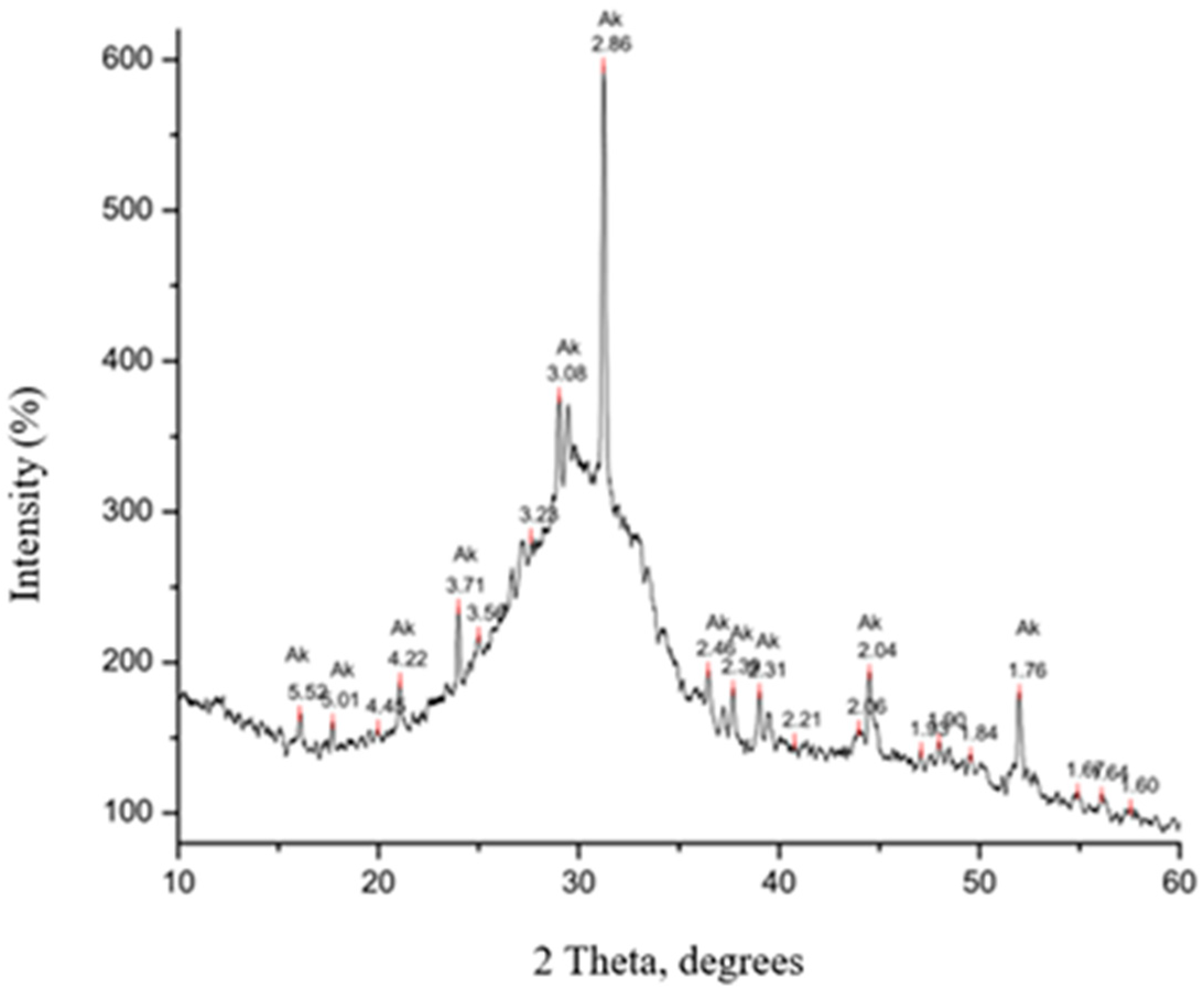
In addition to the high quantities of non-crystallized material, a smaller amount of akermanite (Ak) mineral was identified. The powder diffractogram is shown in Figure 8.
Figure 8.
Diffractogram of the slag sample.
SEM microphotographs of the initial slag sample are shown in Figure 9. A typical slag appearance can be explained by a porous structure with open pores, on the surfaces of which certain crystals can be observed, which, according to the available literature, can be classified as akermanites [42,43].
Figure 9.
SEM image of the slag sample (a) magnification 50x, (b) magnification 200x, (c) magnification 500x and (d) magnification 1000x.
Figure 9.
SEM image of the slag sample (a) magnification 50x, (b) magnification 200x, (c) magnification 500x and (d) magnification 1000x.
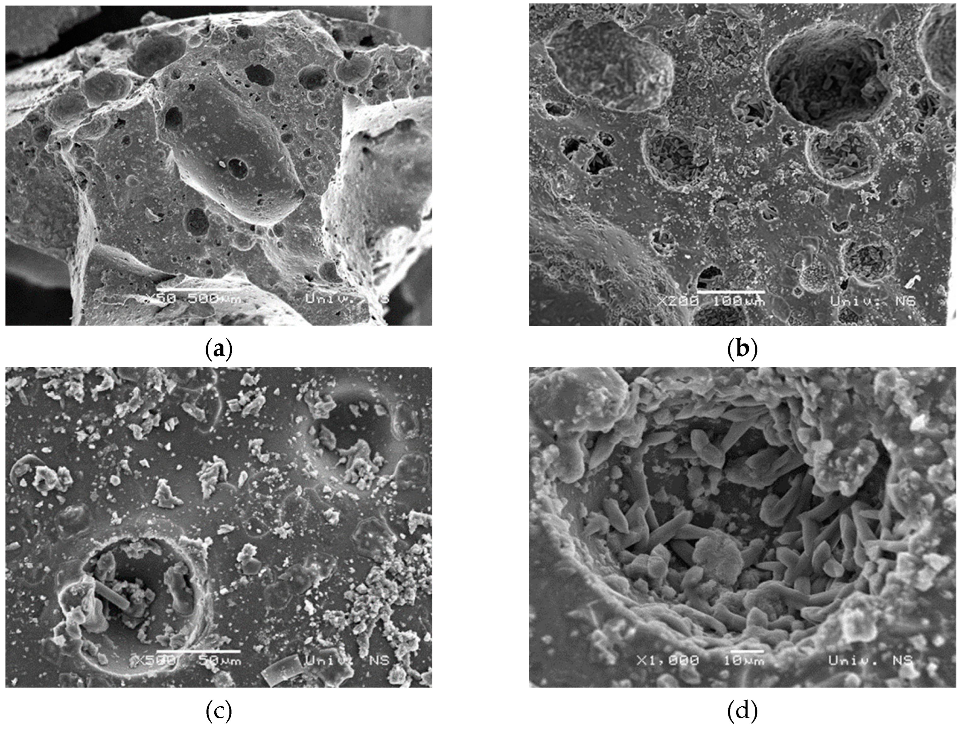
Based on the detailed sample characterization and the obtained results, it was concluded that the tested slag sample can be used as an additive for cement mortars after micronization.
3.2. Physical - chemical characteristics of mortar
A new type of cement was prepared with added 10 mas% slag. After the preparation and curing, with and without slag, in a period of 2, 28 and 240 days, the mortar samples were tested for flexural and compression strength. In addition, the setting time of both cement mixtures was determined and their chemical composition was analyzed. The results of geomechanical tests of standard and laboratory sample prisms of the new mortar system are given in Table 3 and Figure 10.
Table 3.
Mechanical characteristics of standard and laboratory prisms.
| System/ strength | Flexural 2 days, MPa | Compressive 2 days, MPa | Flexural 28 days, MPa | Compressive 28 days, MPa | Flexural 240 days, MPa | Compressive 240 days, MPa |
|---|---|---|---|---|---|---|
| A* standard | 5 | 30.63 | 6.47 | 59.33 | 8.01 | 61.42 |
| Az10 standard | 3.44 | 24.22 | 6.39 | 58.61 | 8.23 | 59.71 |
| A laboratory | 11.44 | 68.90 | 9.58 | 66.29 | ||
| Az10 laboratory | 7.94 | 41.08 | 9.10 | 53.07 |
* Legend: A - CEM I, Az10 -CEM I with the addition of 10 mas% slag, standard 40x40x160 mm and laboratory 10x10x60 mm.
Figure 10.
Mechanical characteristics of standard and laboratory prisms.
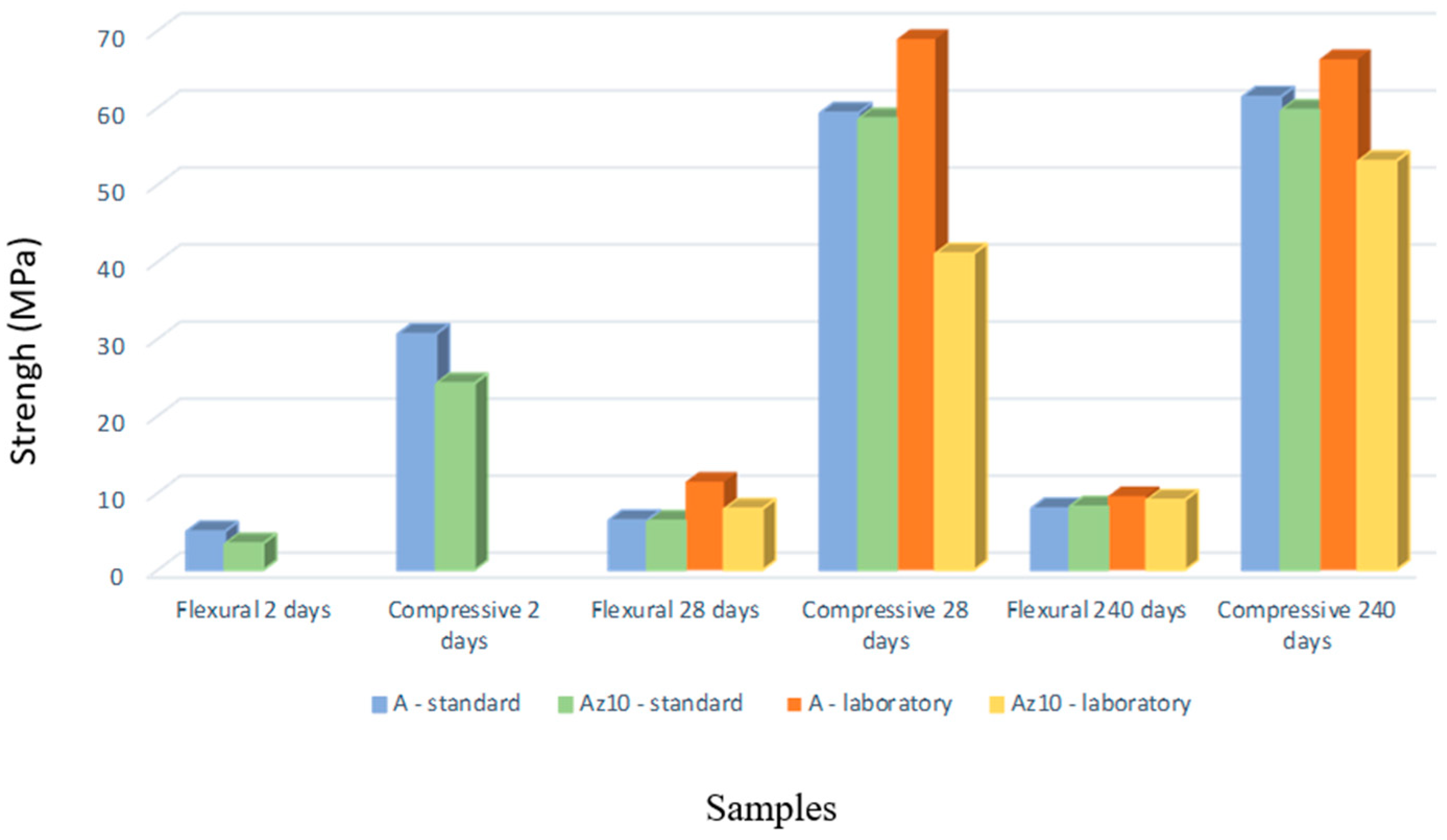
The standard does not prescribe flexural strength values, but they are always given in reports, while compressive strength values are an important parameter that is tested and defined by the standard or based on the Rulebook on Cement Quality [44]. The compressive strength decreases with the addition of slag, but in both systems, the strength increases with the hydration time. By comparing the values obtained for standard and laboratory prisms, it can be concluded that the compressive strength results for standard prisms fully follow the compressive strength values for the laboratory prisms. Thus, the results are comparable. This conclusion is a good indicator that the following experiments can fully rely on laboratory samples and raw materials saving.
The setting time is shown in Table 4.
Table 4.
Alite systems setting time.
| System/ Setting time | Setting to start time, min | Setting to finish time, min | Total setting time, min |
|---|---|---|---|
| A | 86 | 212 | 126 |
| Az10 | 115 | 223 | 108 |
The new slag mortar system has a total setting time of 108 minutes which is shorter than the setting time of CEM I (alite) mortar which is 126 minutes, but takes longer for the setting to start.
The chemical composition of the alite and the new mortar system is shown through silicate analysis given in Table 5.
Table 5.
Chemical composition of the alite and the new mortar system.
| Content, % | |||||||||||
|---|---|---|---|---|---|---|---|---|---|---|---|
| System | SiO2 | Fe2O3 | Al2O3 | CaO | MgO | SO3 | P2O5 | TiO2 | Na2O | K2O | Annealing loss |
| A | 22.10 | 1.57 | 4.45 | 36.16 | 2.11 | 3.15 | 0.10 | 0.28 | 0.55 | 0.65 | 3.85 |
| Az10 | 22.80 | 1.36 | 4.66 | 50.37 | 2.73 | 3.62 | 0.09 | 0.26 | 0.46 | 0.82 | 3.63 |
The chemical composition of the alite and the new mortar system (Az10) is shown based on silicate analysis given in Table 5. The results of the silicate analysis show that the annealing loss in both systems is below the value prescribed by the Rulebook [44]. The sulfate content (as SO3) is below the limit value for both types of cement, so there is no possibility of subsequent sulfate corrosion. The content of CaO is much higher in the slag system, which originates from the slag itself in which it is present with 40.82% and can negatively affect the volume stability of this cement system. The total alkali content expressed as Na2O+K2O is rather high, but these values do not exceed the limit (<1.5). The presence of alkali in the cement can lead to a later reaction with the aggregate in the concrete, causing a decrease in the structure strength [45].
3.3. Chemical characteristics of Danube river water
Danube water used in the experiments was tested for pH, total nitrogen, total phosphorus, total organic carbon, ammonia, nitrates, nitrites, chlorides, COD (Chemical Oxigen Demand), BOD5 (Biochemical Oxigen Demand), sulfates, phosphates, dissolved oxygen, fluorides, hexavalent chromium, calcium, magnesium, manganese, lead, zinc, total chromium, cadmium, copper, mercury, arsenic, iron (Table 6) [46].
Table 6.
Analysis of Danube river water.
| parameter | pH | total nitrogen | total phosphorus | total organic carbon | ammonia | nitrates | |
| measured value | 8.47 | 1.35 | 0.047 | 1.89 | <0.078 | 1.317 | |
| reference value | 6.5-8.5 | 2.0 | 0.2 | 5.0 | 0.3 | 3.0 | |
| parameter | nitrites | COD | BOD5 | sulfates | phosphates | dissolved oxygen | |
| measured value | 0.019 | 8.0 | 1.2 | 37.38 | 0.044 | 8.86 | |
| reference value | 0.03 | 15 | 5.0 | 100 | 0.1 | 7.0 | |
| parameter | fluorides | hexavalent chromium | calcium | manganese | manganese | lead | |
| measured value | <0.5 | <0.1 | 53.0 | 12.86 | 0.01 | <0.01 | |
| reference value | - | 0.1 | - | - | 0.1 | 0.05 | |
| parameter | zinc | total chromium | cadmium | copper | mercury | arsenic | iron |
| measured value | <0.03 | <0.006 | 0.0009 | <0.02 | <0.0003 | <0.01 | 0.122 |
| reference value | 0.7 | 0.05 | 0.005 | 0.022 | 0.001 | 0.01 | 0.5 |
The analysis determined the presence of all tested parameters in values below the maximum allowed, i.e. reference values, so that no negative influence of water was expected in further experiments of the bacterial healing process.
3.4. Bio-stimulated healing of cracks
After setting up the bacterial experiments, the changes in the cracks were monitored with a portable microscope after 7, 14 and 28 days (Table 7 shows the changes after 7 days under three characteristic conditions). In Table 7, all mean values of the change in cracks are shown tabularly (Table 8) and graphicaly (Figure 11).
Table 7.
Changes in the new mortar sample after 7 days under controlled conditions, optical microscopy.
Table 7.
Changes in the new mortar sample after 7 days under controlled conditions, optical microscopy.
| Conditions/days | 0 days | 7 days |
|---|---|---|
| First group/condition | 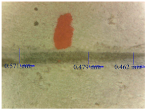 |
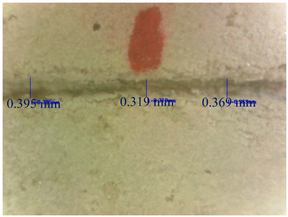 |
| Third group/condition | 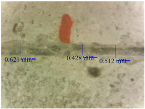 |
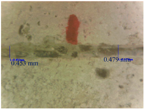 |
| Fifth group/condition | 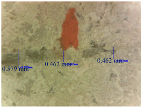 |
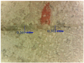 |
Table 8.
Mean crack width of the new mortar system with healing efficiency by conditions.
| Group/condition | |||||
|---|---|---|---|---|---|
| Healing | First | Second | Third | Fourth | Fifth |
| Initial width, mm | 0.504 | 0.466 | 0.567 | 0.567 | 0.569 |
| Width after 7 days, mm | 0.361 | 0.336 | 0.466 | 0.508 | 0.445 |
| Efficiency, % | 28.12 | 27.37 | 16.75 | 9.96 | 22.88 |
| Initial width, mm | 0.542 | 0.659 | 0.638 | 0.487 | 0.588 |
| Width after 14 days, mm | 0.347 | 0.468 | 0.529 | 0.357 | 0.330 |
| Efficiency, % | 32.02 | 29.04 | 16.90 | 26.73 | 42.74 |
| initial width, mm | 0.447 | 0.722 | 0.517 | 0.571 | 0.506 |
| Width after 28 days, mm | 0.346 | 0.483 | 0.407 | 0.399 | 0.357 |
| Efficiency, % | 22.39 | 33.68 | 20.99 | 29.99 | 27.80 |
Figure 11.
Efficiency of the new mortar system by days and conditions.
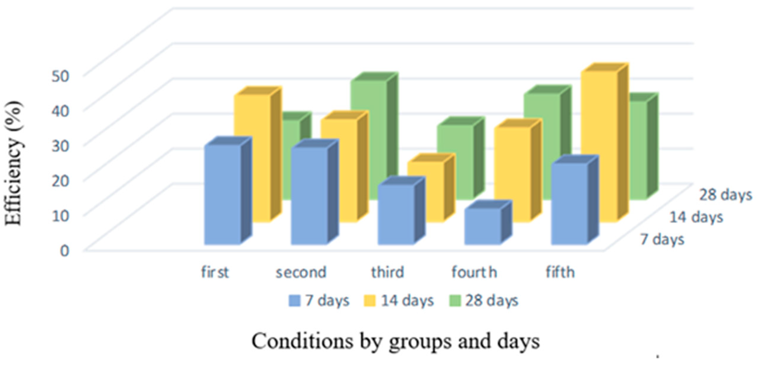
Although, according to literature data, bacteria reach their precipitation maximum after 7 days [29], when they can create a sufficient amount of calcium carbonate to close a 0.5-0.8 mm wide crack [47], the most favorable healing values were recorded with the new slag mortar system after 14 days in both waters, with efficiency being 32.02% and 42.74% for sterile demineralized and Danube water, respectively.
Bio-stimulated healing rates after 7 and 28 days range between 22.39% and 28.12%, respectively. Healing was also recorded under bacteria-free conditions, namely, in sterile demineralized water 20.99% and Danube water 29.99% with initial cracks of about 0.5 mm, which can be explained by the process of autogenous healing due to unreacted mortar and slag grains [13,15].
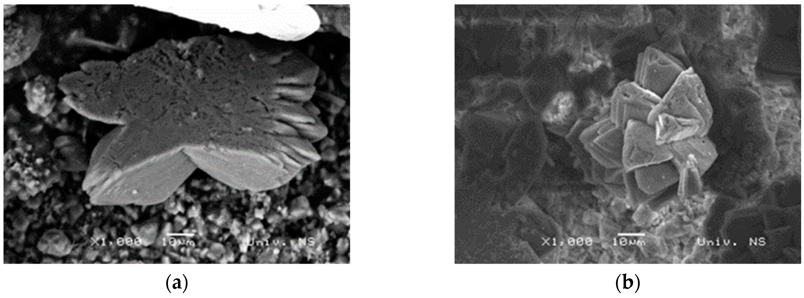
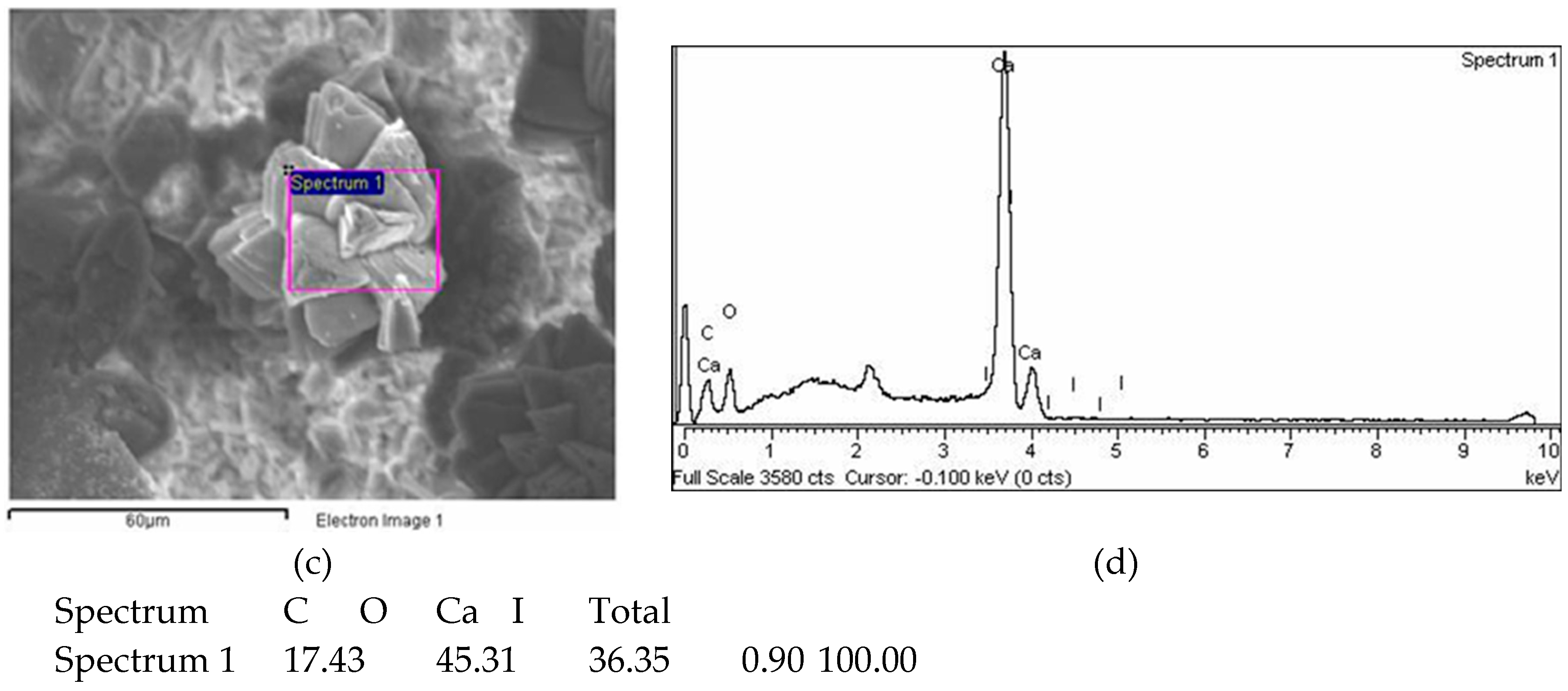
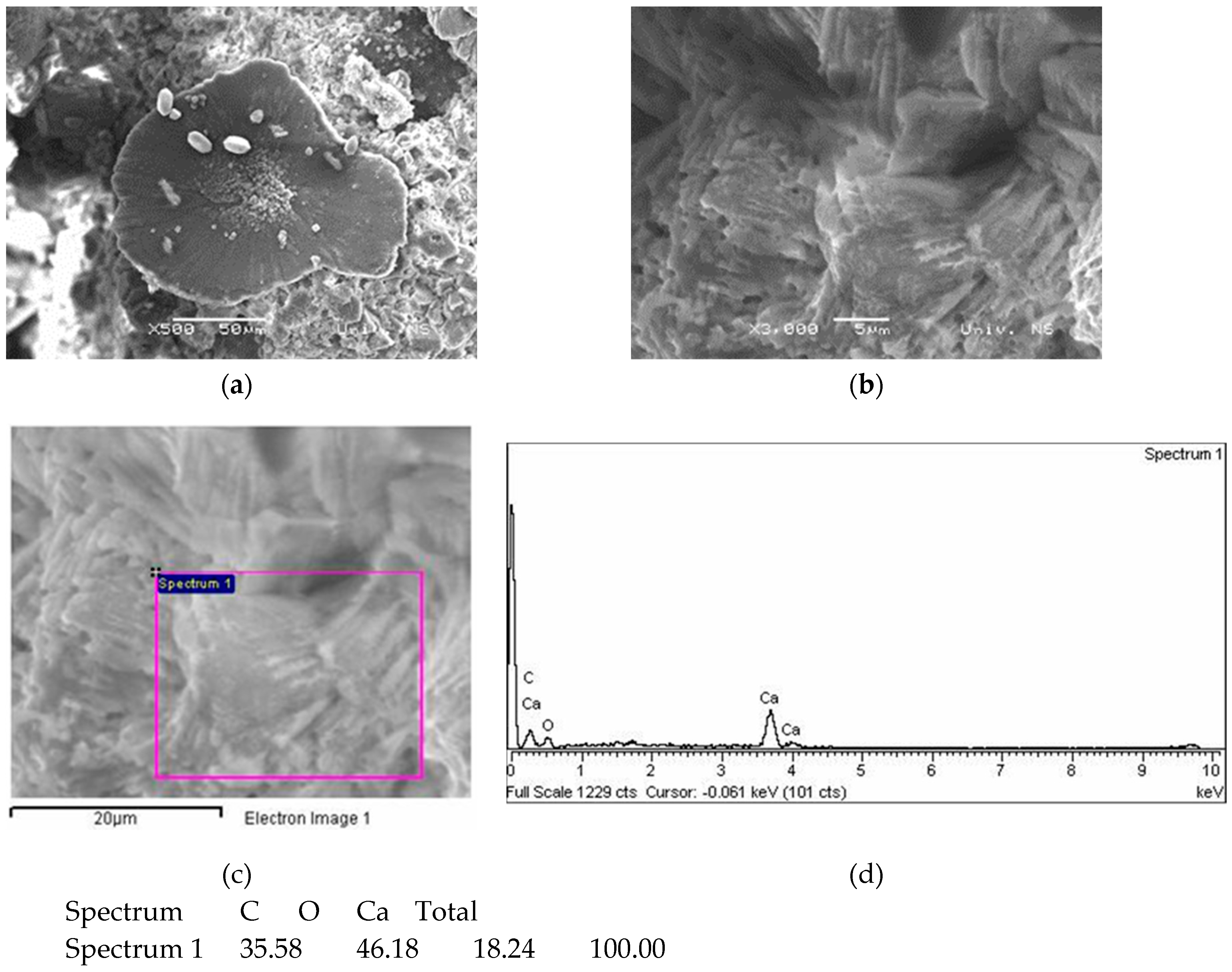
Figure 12 (a) and (b) shows SEM images of the sample with bacteria in sterile demineralized water at 1000 x magnifications and the characteristic morphology of calcite crystals that started the process of bio-stimulated healing in the cracks as the result of bacterial precipitation. The appearance of the crystals is confirmed by the previous studies [48]. The EDS spectrum in Figure 12 (c) and (d) confirms the presence of calcium, oxygen and carbon, which once again indicates that it is calcium carbonate. Previously published studies show that the main healing product is also calcium carbonate [17], which was confirmed in this research.
Figure 12.
SEM, EDS results of the sample with bacteria in sterile demineralized water (a) and (b) 1000x magnification, (c) and (d) EDS spectrum at 1000x magnification.
Figure 12.
SEM, EDS results of the sample with bacteria in sterile demineralized water (a) and (b) 1000x magnification, (c) and (d) EDS spectrum at 1000x magnification.
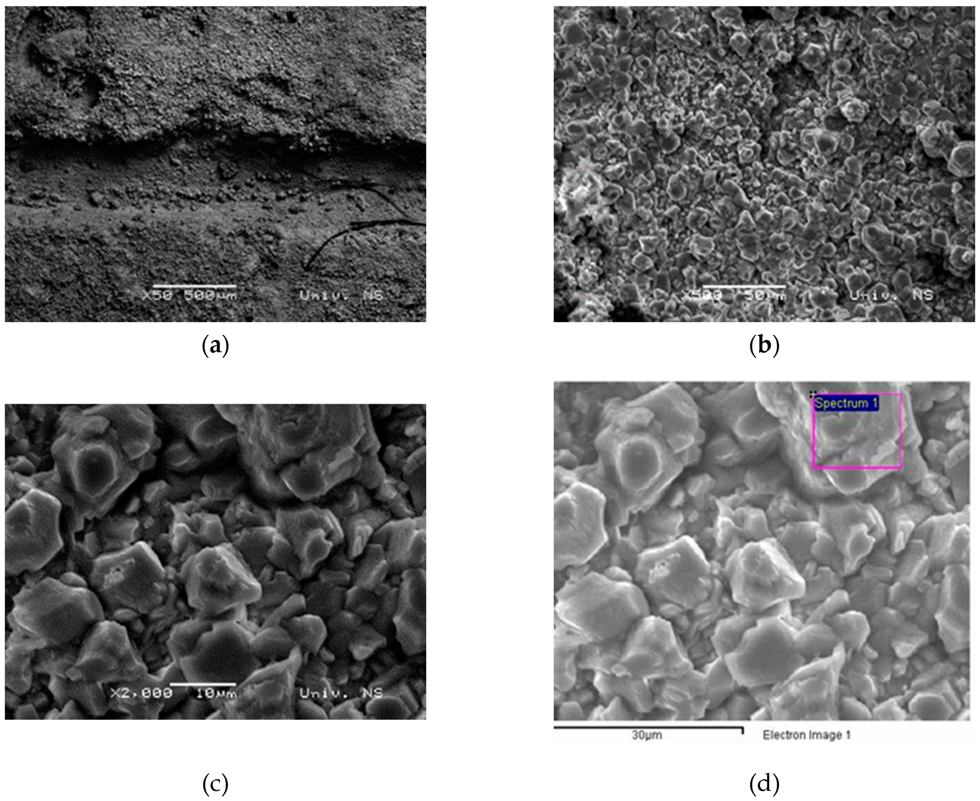
SEM images of the sample (Figure 13 (a)) in the sterile demineralized water without nutritient and bacterial culture show that the crack has not self-healed and the crystals at 500x and 2000x magnifications (Figure 13 (b) and (c)) are characteristic of slag mortars and are in line with previously published studies [49].
Figure 13.
SEM, EDS images of the sample without bacteria in sterile demineralized water (a) 50x magnification, (b) 500x magnification, (c) 2000x magnification, (d) and (e) EDS spectrum at 2000x magnification.
Figure 13.
SEM, EDS images of the sample without bacteria in sterile demineralized water (a) 50x magnification, (b) 500x magnification, (c) 2000x magnification, (d) and (e) EDS spectrum at 2000x magnification.
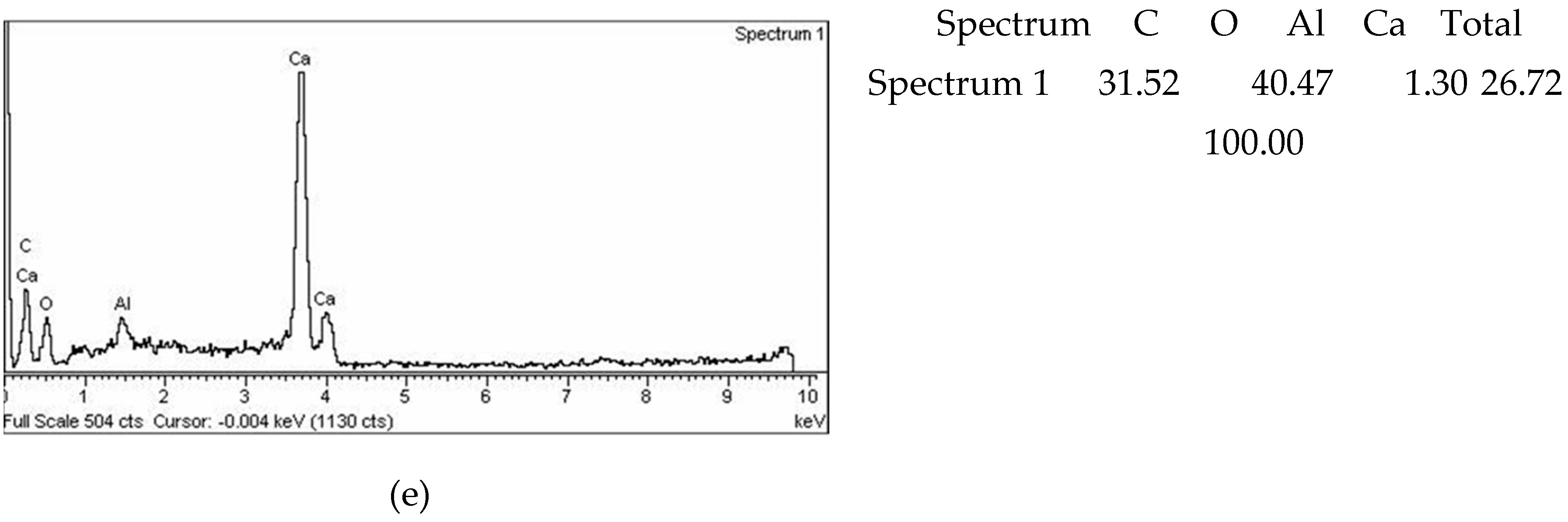
The SEM images and EDS of the sample treated with bacteria in Danube water (Figure 14) also confirmed the precipitation of calcium carbonate as the main compound that fills the cracks and leads to healing process. Calcium carbonate crystals are larger with clear rosettes, unlike crystals formed in sterile demineralized water where the crystals are smaller and more uniform.
Figure 14.
SEM, EDS results of the sample with bacteria in Danube water a) 500x magnification, b) and c) EDS spectrum at 3000x magnification.
Figure 14.
SEM, EDS results of the sample with bacteria in Danube water a) 500x magnification, b) and c) EDS spectrum at 3000x magnification.
3.5. The success of crack image classification using CNN
ResNet50 program package within Matlab2023A was used to classify images of cracks in the new slag mortar system after a period of bacterial treatment in sterile demineralized and Danube water.
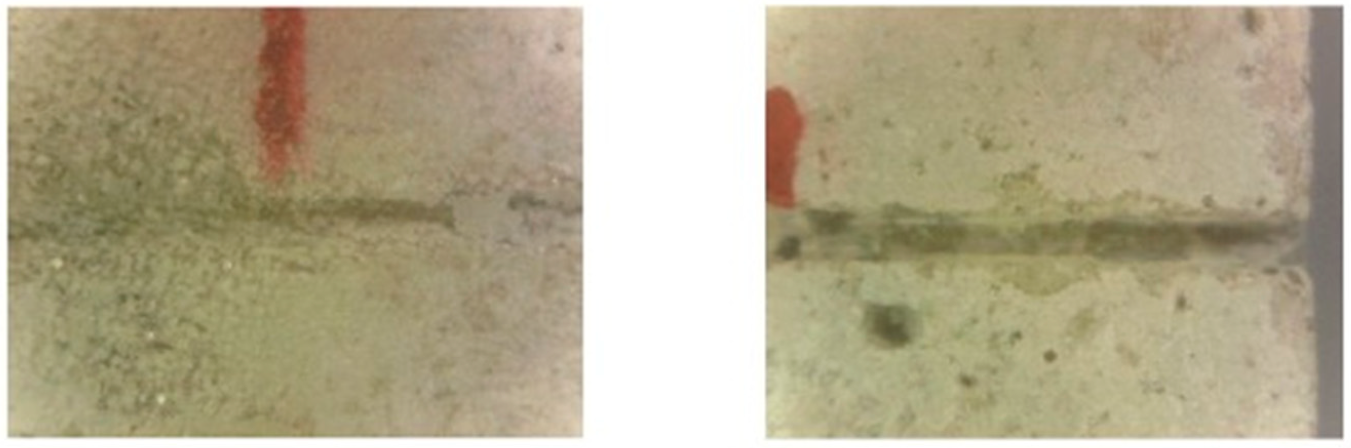
The microscopic images showing bacterial healing in sterile demineralized water and in Danube water are visually very similar and can be classified into the same data set (Class 1). For the second data set (Class 2), images from mortar samples with demineralized water without nutritient and bacterial culture, were selected.
Each group had 102 input images. After entering the input data into the network, the program extracts one image from each group as shown in Figure 15.
Figure 15.
Typical image of a sample from the group left) with bacteria and right) without bacteria.
Figure 15.
Typical image of a sample from the group left) with bacteria and right) without bacteria.
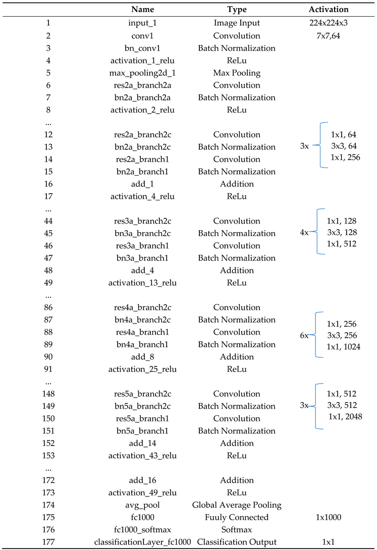
The CNN had 177 nodes with 192 connections classified into input, convolutional, pooling, fully connected, ReLu and output layers. Figure 16 shows the simplified architecture of convolutional neural network 50-layer ResNet while the network architecture is broken down by layers as given in Table 9.
Figure 16.
Simplified architecture of convolutional neural network 50-layer ResNet, showing convolutional layers (C1,1, C2,1, … C5,9), pooling layers (P1 and P2) and a fully connected layer (FC1).
Figure 16.
Simplified architecture of convolutional neural network 50-layer ResNet, showing convolutional layers (C1,1, C2,1, … C5,9), pooling layers (P1 and P2) and a fully connected layer (FC1).
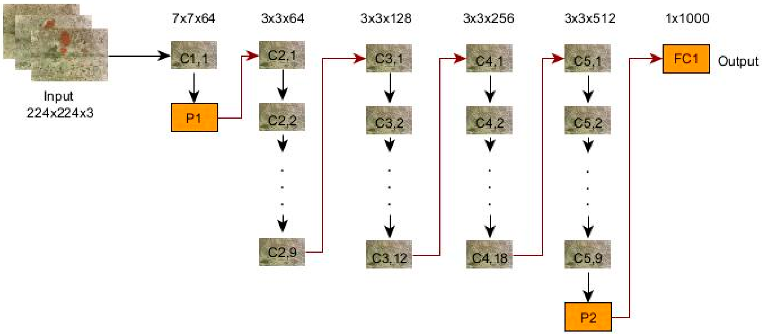
Table 9.
Architecture of the resulting network.
For network training and for the test, the program selected 62 (30 %) and 142 (70 %) input images, respectively. The first covolutional matrix with the number of images obtained by the test is:
| 59 | 12 |
| 11 | 60 |
After reprocessing the data through the network, a generated matrix was obtained, shown with accuracy in relation to the number of images from the test (Figure 17):
Figure 17.
Generated matrix.
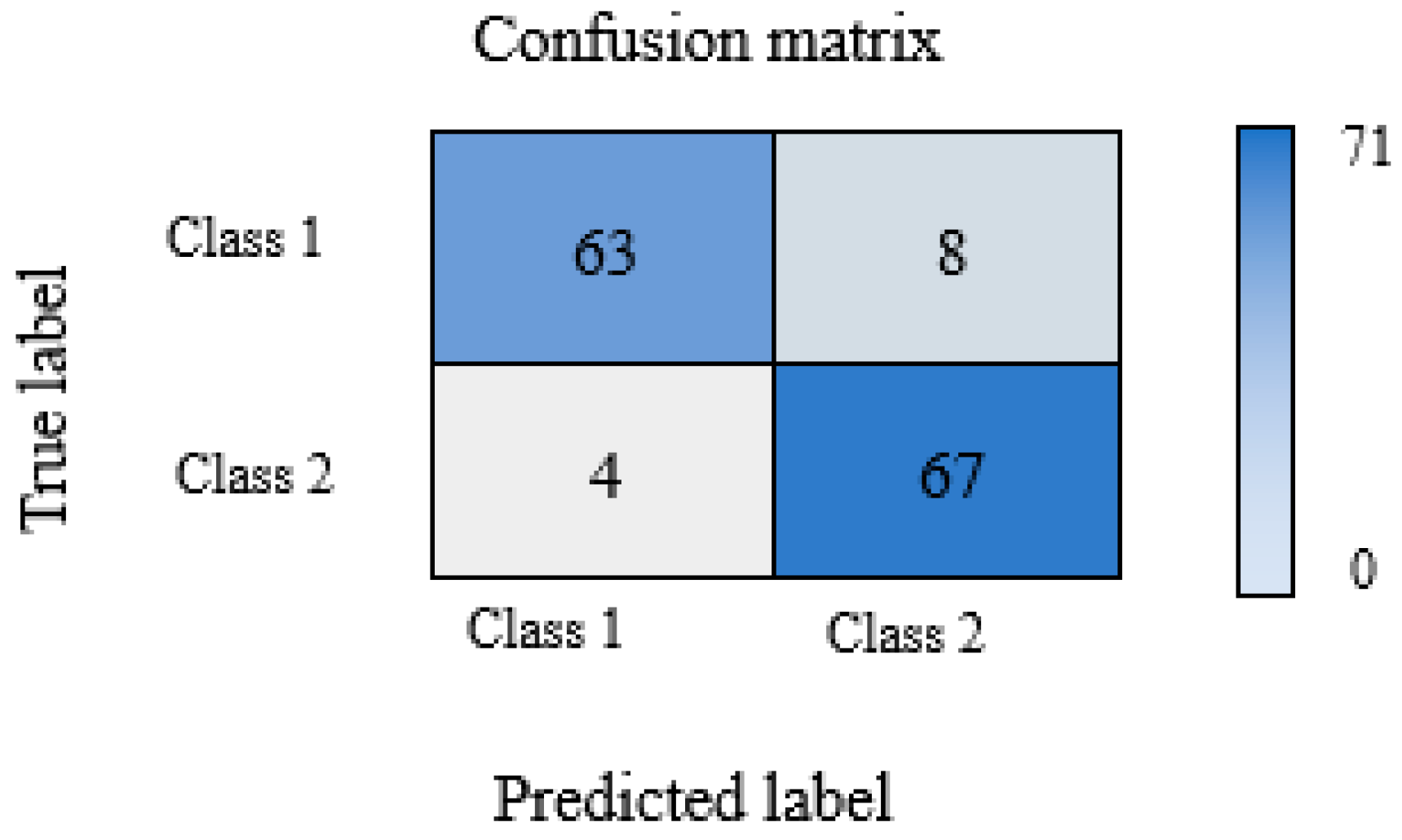
The final classification accuracy using this deep learning model is 91.55%.
To validate the classification results, a new data set with 18 images for each group was selected. After validation, a deviation was obtained in the group with bacteria for one input image (5.5 %), while in the group without bacteria the deviation for two input images was (11 %).
Validation success is also obtained from Equations (1) to (4) and the results are given in table 10.
Table 10.
Indicators for each class.
| Indicators | Precision | Recall | F1 - score | Accuracy |
|---|---|---|---|---|
| Class 1 | 0.94029 | 0.88732 | 0.91303 | 0.91549 |
| Class 2 | 0.89333 | 0.94366 | 0.91781 |
The characteristics obtained in this way confirmed the obtained validation values and amount to 91.55%.
Based on the obtained CNN network data, it can be concluded that the model is suitable for the classification of images of changes in mortar sample cracks.
4. Conclusion
This complex research concludes that up to 10 mas% of blast furnace slag can be successfully added to cement mortars without compromising the geomechanical and chemical properties of the mortar. Further research on the bio-stimulated healing process confirmed that this quantity of slag is optimal as, in combination with bacteria, it promotes autogenous healing. For the bio-stimulated healing process, the S. pasteurii DSM 33 strain was selected, which is characterized by a high capacity of continuous production of carbonate and bicarbonate ions through ureolysis [11,29]. Although the bacteria reach their precipitation maximum after 7 days, current research has proven that in controlled conditions of humidity and temperature, greater healing efficiency can be achieved with a longer aging time (14 and 28 days). According to the knowledge of the authors of this work, such research for the first time included Danube river water which, based on SEM images, has a favorable effect on the formation of calcium carbonate crystals, making healing efficiency about 10% higher compared to the conditions of bacteria in sterile demineralized water. The beginning of autogenous healing was recorded in control conditions, mortar samples in demineralized water without bacteria and nutritient. Here, the efficiency ranged from 16.75% to 20.99%. Considering the success of the experiments and the multitude of recorded microscopic changes, images were also classified by convolutional neural networks. Convolutional neural networks are widely used in practice for the classification of various types of images, but according to the available literature, such an approach is not recorded for images of crack bio-stimulated healing in new types of mortar. As a result of the classification, a high percentage of accuracy of 91.55% was obtained, while during validation, the deviation was as low as 5.5% in the group with bacteria and 11% in the group without bacteria
Author Contributions
Conceptualization, J.N., J.R., M.T. and S.V.; Methodology, J.N., J.R. and S.V.; Formal analysis and investigation, J.N., I.J., S.M., S.V.; Sampling, dating and analysis J.N. and I.J. Writing—original draft J.N, J.R., M.T., I.J. and S.V. All authors have read and agreed to the published version of the manuscript.
Funding
The authors would like to acknowledge the support from Ministry of Science, Technological Development and Innovations (Serbia), project No. 451-03-47/2023-01/200134, No. 451-03-47/2023-01/200131 and No. 451-03-47/2023-01/200035.
Data Availability Statement
The data presented in this study are available on request from the corresponding author.
Acknowledgments
The authors are particularly grateful to Laboratory for materials in cultural heritage (Faculty of Technology Novi Sad), Laboratory of Crystallography (Faculty of Mining and Geology Belgrade), University Center for Electron Microscopy in Novi Sad (University of Novi Sad), Mining institute Belgrade, Thermal Power Plant Kostolac B, Ministry of Education, Science and Technological Development of the Republic of Serbia.
Conflicts of Interest
The authors declare no conflict of interest.
References
- Mahmod, A. K.; Al-Jabbar, L.A.; Salman M. M. Bacteria Based Self-Healing Concrete : A Review, 2 nd online Scientific conference for Graduate Engineering Students, Journal of Engineering and Sustainable Development, 2021, 43-56.
- Suleiman, A. R.; Zhang, L. V.; Nehdi, M. L. Quantifying Crack Self-Healing in Concrete with Superabsorbent Polymers under Varying Temperature and Relative Humidity, Sustainability 2021, 13, 13999. [CrossRef]
- Termkhajornkit, P.; Nawa, T.; Yamashiro, Y.; Saito, T. Self-healing ability of fly ash–cement systems, Cement and Concrete Composites 31, 2009, 195–203. [CrossRef]
- Van Breugel, K. Is there a market for self-healing cement-based materials, Proceedings of the First International Conference on Self Healing Materials, Noordwijk aan Zee, The Netherlands, 2007. 1-9.
- Van Tittelboom, K.; De Belie, N. Self-Healing in Cementitious Materials—A Review, Materials, 2013, 6, 2182-2217. [CrossRef]
- Mors, R. M.; Jonkers, H. M. Bacteria-Based Self-Healing Concrete – Introduction, Second International Conference on Microstructural-related Durability of Cementitious Composites, Amsterdam, The Netherlands, 2012, 1-7.
- Mauludin, L. F.; Oucif, C. Modeling of Self-Healing Concrete: A Review, Journal of Applied Computational Mechanics, 5, 3, 2019, 526-539.
- Zhuang, X.; Zhou, S. The Prediction of Self-Healing Capacity of Bacteria-Based Concrete Using Machine Learning Approaches CMC, 2019, vol. 59, no. 1, 57-77.
- Huang, X.; Sresakoolchai, J.; Qin, X.; Fan Ho, Y.; Kaewunruen, S. Self-Healing Performance Assessment of Bacterial-Based Concrete Using Machine Learning Approaches, Materials, 2022, 15, 4436. [CrossRef]
- Zhutovsky, S., Nayman, S. Modeling of crack-healing by hydration products of residual cement in concrete, Construction and Building Materials, 340, 2022, 127682. [CrossRef]
- Van der Bergh, J. M.; Miljević, B.; Šovljanski, O.; Vučetić, S.; Markov, S.; Ranogajec, J.; Bras, A. Preliminary approach to bio-based surface healing of structural repair cement mortars, Construction and Building Materials, 248, 2020, 118557.
- Roy, R. Bacteria-based self-healing mortar with bio-plastic healing agents, Kth Royal Institute of Technology School of Architecture And The Built Environment, 2020, 176.
- Grubišić, I. Samozacjeljivanje betona autogenim i autonomnim postupkom s naglaskom na metodu bakterija, Diplomski rad, Sveučilište u Splitu, Fakultet građevinarstva, arhitekture i geodezije, 2020. in Serbian.
- Zhang, W.; Zheng, Q.; Ashour, A.; Han, B. Self-healing cement concrete composites for resilient infrastructures: A review, Composites Part B 189, 2020, 107892. [CrossRef]
- Guzlena, S.; Sakale, G. Self-healing concrete with crystalline admixture – a review, IOP Conf. Series: Materials Science and Engineering 660, 2019, 012057. [CrossRef]
- Van der Bergh, J. M.; Miljević, B.; Vučetić, S.; Šovljanski, O.; Markov, S.; Riley, M.; Ranogajec, J.; Bras, A. Comparison of Microbially Induced Healing Solutions for Crack Repairs of Cement-Based Infrastructure, Sustainability 2021, 13, 4287.
- Li, G.; Liu, S., Niu, M.; Liu, Q.; Yang, X.; Deng, M. Effect of granulated blast furnace slag on the self-healing capability of mortar incorporating crystalline admixture, construction and building materials 239, 2020, 117818. [CrossRef]
- Šovljanski, O.; Tomić, A.; Markov, S. Relationship between Bacterial Contribution and Self-Healing Effect of Cement-Based Materials, Microorganisms 2022, 10, 1399. [CrossRef]
- Sagripanti, J. L.; Bonifacino, A. Comparative Sporicidal Effects of Liquid Chemical Agents, Applied and Environmental Microbiology, Vol. 62, No. 2, 1996, 545–551. [CrossRef]
- Algaifi, H. A.; Abu Bakar, S.; Sam, A. R. M.; Abidin, A. R. Z.; Shahir, S.; AL-Towayti, W. A. H. Numerical modeling for crack self-healing concrete by microbial calcium carbonate, Construction and Building Materials, 189, 2018, 816-824. [CrossRef]
- Althoey, F.; Amin, M. N.; Khan, K.; Usman, M. M.; Ali Khan, M.; Javed, M. F.; Sabri, M. M. S.; Alrowais, R.; Maglad, A. M. Machine learning based computational approach for crack width detection of self-healing concrete, Case Studies in Construction Materials, 17, 2022, e01610. [CrossRef]
- Technical documentation of the Department of Carbohydrate Foods of the Faculty of Technology in Novi Sad.
- Documentation of the Mining Institute.
- Documentation of the Faculty of Mining and Geology in Belgrade.
- Documentation of the University Center for Electron Microscopy in Novi Sad (Department of Biology and Ecology, Faculty of Science).
- Standard SRPS EN 196-3:2017.
- Standard SRPS EN 196-1:2017.
- Žarković, D. B. Jonska hromatografija – razvoj metode za analizu i kontrolu kvaliteta vode u proizvodnji papira, doktorska disertacija, Tehnološko–metalurški fakultet, Univerzitet u Beogradu, 2011. in Serbian.
- Šovljanski, O. Mikrobiološka precipitacija karbonata –od odabira induktora do ispitivanja bioprocesnih parametara, doktorska disertacija, Tehnološki fakultet Novi Sad, 2021. in Serbian.
- Ševo, I. Specijalizovana neuronska mreža za klasifikaciju i segmentaciju aero-snimaka, doktorska disertacija, Elektrotehnički fakultet, Univerzitet u Banjoj Luci, 2020. in Serbian.
- Neuronske mreže i duboko učenje Mašinsko učenje 2020/21. Matematički fakultet Univerzitet u Beogradu, in Serbian.
- Matoš, I. Klasifikacija prometnih znakova korištenjem konvolucijskih neuronskih mreža, diplomski rad, Fakultet elektrotehnike, računarstva i informacijskih tehnologija, Sveučilište Josipa Jurja Strossmayera u Osijeku, 2020. in Croatian.
- Shang, K. FSA, CFA, PRM, SCJP, Applying Image Recognition to Insurance, Society of Actuaries Research Expanding Boundaries Pool, 2018.
- Repić, M.; Ralević, N. Primena konvolucionih neuralnih mreža kod prepoznavanja slika u osiguranju, Zbornik radova Fakulteta tehničkih nauka, Novi Sad, UDK: 517.98 DOI: https://doi.org/10.24867/13JV01Repic. [CrossRef]
- Zariea, M.; Jahedsaravania, A.; Massinaeib, M. Flotation froth image classification using convolutional neural networks Minerals Engineering, 155, 2020, 106443.
- Lu, F.; Liang, Y.; Wang, X.; Gao, T.; Chen, Q.; Liu, Y.; Zhou, Y.; Yuan, Y.; Liu, Y. Prediction of amorphous forming ability based on artificial neural network and convolutional neural network, Computational Materials Science, 210, 2022, 111464. [CrossRef]
- Nakhaei, F.; Rahimi, S.; Fathi, M. Prediction of Sulfur Removal from Iron Concentrate Using Column Flotation Froth Features: Comparison of k-Means Clustering, Regression, Backpropagation Neural Network, and Convolutional Neural Networ, Minerals 2022, 12, 1434. [CrossRef]
- https://hashdork.com/sr/neural-network/.
- Dabović, M. M.; Tartalja, I. I. Duboke konvolucijske neuronske mreže – koncepti i aktuelna istraživanja, Zbornik 61. Konferencije za elektroniku, telekomunikacije, računarstvo, automatiku i nuklearnu tehniku, ETRAN 2017, ISBN 978-86-7466-692-0, VI1.1.1-6. in Serbian.
- Gao, X.; Tang, Z.; Xie, Y.; Zhang, H.; Gui, W. A layered working condition perception integrating handcrafted with deep features for froth flotation, Minerals Engineering 170, 2021, 107059. [CrossRef]
- Bušatlić, I.; Bušatlić, N.; Merdić, N.; Haračić, N. Osnove hemije i tehnologije portland cementa, Zenica, 2020, ISBN 978-9958-17-168-0, p. 385. in Bosnian.
- Duana, P.; Shuia, Z.; Chena, W.; Shenb, C. E nhancing microstructure and durability of concrete from ground granulated blast furnace slag and metakaolin as cement replacement materials, J. Mater. Res. Technol. 2013, 2, 1, 52-59.
- Han, Z.; Feng, P.; Gao, C.; Shen, Y.; Shuai, C.; Peng, S. Microstructure, mechanical properties and in vitro bioactivity of akermanite scaffolds fabricated by laser sintering, Materials Science, DOI:10.3233/BME-141017,. [CrossRef]
- Pravilnik o kvalitetu cementa ("Sl. glasnik RS", br. 34/2013 i 44/2014) in Serbian.
- Ilić, I. Mogućnost primene mikroniziranog i klasiranog elektrofilterskog pepela kao aditiva za proizvodnju građevinskih materijala, Magistarska teza, Rudarsko–geološki fakultet, Univerzitet u Beogradu, 2009. in Serbian.
- Archive of technical documentation of Thermal Power Plant Kostolac.
- Grubišić, I. Samozacjeljivanje betona autogenim i autonomnim postupkom s naglaskom na metodu bakterija, Diplomski rad, Sveučilište u Splitu, Fakultet građevinarstva, arhitekture i geodezije, 2020. in Croatian.
- Vučetić, S.; Čjepa, D.; Miljević, B.; van der Bergh, J. M.; Šovljanski, O.; Tomić, A.; Nikolić, E.; Markov, S.; Hiršenberger, H.; Ranogajec, J. Bio-Stimulated Surface Healing of Historical and Compatible Conservation Mortars, Materials 2023, 16, 642.
- Schneider, N.; Stephan, D. Reactivation of a Retarded Suspension of Ground Granulated Blast-Furnace Slag, Materials 2016, 9, 174. [CrossRef]
Disclaimer/Publisher’s Note: The statements, opinions and data contained in all publications are solely those of the individual author(s) and contributor(s) and not of MDPI and/or the editor(s). MDPI and/or the editor(s) disclaim responsibility for any injury to people or property resulting from any ideas, methods, instructions or products referred to in the content. |
© 2023 by the authors. Licensee MDPI, Basel, Switzerland. This article is an open access article distributed under the terms and conditions of the Creative Commons Attribution (CC BY) license (http://creativecommons.org/licenses/by/4.0/).
Copyright: This open access article is published under a Creative Commons CC BY 4.0 license, which permit the free download, distribution, and reuse, provided that the author and preprint are cited in any reuse.


