Submitted:
07 June 2023
Posted:
08 June 2023
You are already at the latest version
Abstract
A novel simplifying Volterra structure algorithm is proposed for intensity modulation direct detection (IM-DD) optical fiber short distance communication system by using the decision feedback equalization algorithm (DFE). Based on this algorithm, the signal damage for four-level pulse amplitude modulation signal (PAM-4) is compensated, which is caused by device bandwidth limitation and dispersion during transmission. Experiments have been carried out using a 25GHz Electro-absorption Modulated Laser (EML), showing that PAM-4 signals can transmit over 10km in standard single-mode fiber (SSMF). The 112Gbps and 128Gbps signals can reach the error rate threshold of KP4-FEC (BER=2*10-4) and HD-FEC (BER=3.8*10-3), respectively. The simplified principle and process of proposed Volterra-based equalization algorithm are presented. Experimental results show that the algorithm complexity is greatly reduced by 75%, which provides an effective theoretical support for the commercial application of this algorithm.
Keywords:
optical fiber data communication system
; EML
; PAM4
; Volterra
; DFE
1. Introduction
In recent years, with the emergence of 5G, 4k/8k HD video, cloud computing and other new applications, as well as the massive demand for data from artificial intelligence, the traffic of short-distance optical transmission has shown explosive growth. A large number of connections within and between data centers urgently require a larger capacity of short-range optical transmission systems to support this part of traffic [1]. At present, the transmission rate of data centers has basically realized the commercial scheme of 400Gbit/s, and is moving towards 800Gbit/s or even 1.6Tbit/s [2]. Different from long distance optical communication systems, short distance transmission systems are very sensitive to cost, power consumption, complexity and other factors. Therefore, in the design of the system, the transmission efficiency, device cost and signal processing scheme need to have a comprehensive consideration.
IM-DD (intensity modulation and direct detection) systems are usually adopted in the scenario of optical interconnection of data centers. In order to control transmission costs, short-range transmission systems are often limited by device bandwidth. In recent studies, various high-order modulation formats have been proposed to improve the spectral efficiency of signals such as PAM (pulse amplitude modulation), discrete multi-tone (DMT), carrier-free amplitude and phase modulation (CAP, carrier-less amplitude and phase), etc. [3,4], among which four-level pulse amplitude modulation (PAM-4) is favored for its simple implementation and high spectral efficiency. The IEEE802.3 research team has also proposed various implementation schemes for 400Gbit/s and 800Gbit/s. However, in IM-DD system, there will still be various limitations, such as inter-signal crosstalk (ISI) caused by insufficient system bandwidth, frequency selective fading effect caused by laser chirp and dispersion and signal distortion caused by receiver square rate detection [4].
In order to further improve the transmission rate and distance of the system, especially to break through the transmission limit under the condition of keeping low-cost components, DSP (digital signal processing) technology has become a new research hot spot. Feed Forward Equalizer (FFE) and Decision Feedback Equalization (DFE) are two widely used equalization techniques. These two equalizers are simple in structure and can eliminate the linear distortion of the signal at the receiving end. But in IM-DD system, nonlinear distortion is inevitable, including frequency power fading effect caused by laser chirp and dispersion as well as signal-signal beat noise (SSBN) caused by receiver square law detection. In this case, the equalizer with Volterra structure can effectively eliminate the nonlinear damage of signal. In [4], a 50km transmission of 50 Gb/s PAM4 signal is demonstrated using a direct modulated laser with a bandwidth of 10GHz, in which a 275-tap Volterra equalizer is used. The transmission achieved -6dBm at a bit error rate of 4.7×10⁻³. There is also an 80km transmission with 50Gbps PAM4 using C-Band DML, in which a Volterra-DFE post-equalizer is used. The BER finally reaches SD-FEC limit (2.2×10⁻²) [5]. In addition, equalization algorithms using maximum likelihood sequence estimation (MLSE) have also been studied recently. A transmission of 56Gb/s PAM-4 signals over 26.4km SSMF single-mode fiber has been demonstrated using 23GHz MZM and PIN-TIA detectors [6]. There are also researchers achieving a 112Gbps C-band transmission by using transmitter-side Tomlinson-Harashima precoding (THP) and MLSE [7]. Although there is a relatively good compensation for signal transmission damage, the structure of Volterra equalizer and maximum likelihood sequence estimation algorithm is complex and requires large memory and power consumption, which will increase the operation cost of the system, so there is still a long distance to go before the commercialization.
In this paper, the Volterra structure is simplified by the derivation of signal transmission and the absolute value operation is proposed to replace the square operation, by which a simplified second-order Volterra-DFE equalizer is realized. The complexity of this equalizer is compared with other related equalizers. Finally, in our experiments based on a 25GHz-bandwidth electrical absorption modulated laser (EML), 112Gbit/s and 128Gbit/s PAM-4 signals can transmit over 10km. By comparing the equalization effects of different equalizers, the feasibility of the algorithm proposed is proved.
2. Principle of simplified second-order Volterra-DFE equalizer
2.1. Volterra transmission model for EML-IMDD systems
Considering the nonlinear damage of signals in short-range transmission systems, such as the nonlinear effect of optical fiber, the frequency fading effect caused by the interaction of laser chirp and dispersion, and the signal-signal beat noise (SSBN), the nonlinear equalizer with Volterra structure has been widely used and studied by researchers. The traditional second-order Volterra equalizer can be expressed as
where and denote input and output signal; and represent the first and second Volterra kernel coefficients; and are the corresponding memory length. It should be noted
that the first and second terms in equation (1) are dedicated to deal with
linear distortion and SSBN noise. The computational complexity is mainly
determined by the second kernel, whose number are . During equalization
process, the kernels coefficients can be obtained at the training stage by
algorithm.
The DFE equalizer can be represented as a transverse filter [7]. Unlike the FFE equalizer, the DFE equalizer combines the feedforward portion and the portion of the symbol value that has been decided together to produce an estimate of the current symbol. The use of feedback equalizer makes the DFE equalizer nonlinear, which can effectively reduce the crosstalk of the previously sent symbol sequence to the currently decided symbols. The principle of decision feedback equalizer can be expressed as
2.2. Second-order Volterra transmission model for EML-IMDD systems
In order to simplify the Volterra-DFE equalizer, we derive the second-order Volterra transmission model for the IMDD system based on the physical model of the photoelectric device used in practice. The transmission model shows that in the second-order beat noise term of the received signal, the coefficient of the signal square term is much larger than that of the delayed signal product term.
First, the normalized optical field of EML output is expressed as
where and represent the normalized current signal of the modulated laser and optical phase. The optical phase is determined by the frequency chirp of the EML laser, which can be expressed as [8]
Where is the linewidth enhancement factor of EML. From the formula , the phase can be written as
Here, the first term on the right has nothing to do with data modulation and can be eliminated in derivation. We only consider the second term and put it into equation (3). The normalized optical field expression can be written as
Since the fiber channel can be modeled as a linear time-invariant system, the optical signal can be expressed as after transmission through the fiber, where is the pulse response of the fiber and is the convolution operator. After direct detection or called square law detection at the receiver, the discrete received signal at the time exponent n can be expressed as , that is, the signal multiplied by its conjugate. If and are converted into discrete time form and , can be expressed as
where means taking the real part. The impulse response of fiber channel in discrete time domain is given by the following formula [9]
where is the dispersion coefficient of the fiber, is the wavelength of the optical carrier, is the length of the fiber, and is the sampling period. The value range of is
Where is the down operation of integer. And if we simplify this further, we get
The linear and nonlinear parts of can be obtained by combining the first-order and second-order terms about with similar terms respectively
Where linear kernels and nonlinear kernels can be expressed as
In the nonlinear kernel described in the formula, the second-order term mainly represents the beat noise caused by the square law detection at the receiver.
In order to study the nonlinear kernels, optical fiber parameters are substituted into equations (12) ~ (14), and the kernel values of signal square terms and non-square terms can be obtained, as shown in . The values of the parameters are dispersion , wavelength , fiber length and EML chirp coefficient ,respectively.
As can be seen from the Figure 1, for EML laser, when , that is, when the corresponding beat terms are the signal square terms, its kernel coefficients are much larger than the nonlinear kernel coefficients when . This indicates that in the second-order nonlinear terms, the signal square terms have a greater influence on the received signal than other nonlinear terms. This is because in the O-band, the crosstalk between the signal numbers caused by fiber dispersion is small. After the detection by the square law in the receiver, the beating noise is dominated by the signal square terms. According to this result, Volterra's nonlinear kernels can be deleted to remove unnecessary second-order nonlinear terms to simplify the structure of the equalizer.
2.3. The Construction of Simplified Equalizer
For the traditional Volterra structure, the second-order kernel coefficient of Volterra can first be written into the matrix structure as shown in Figure 2, whose memory size is N=5, which represents the product term between the signal itself and the five symbols before and after it. We can see that the main diagonal represents the square term of the signals, and the other diagonal represents the product term of the neighboring signals, where there are 15 kernel coefficients, which correspond to 15 different product terms.
As the length of signal memory increases, the number of kernels increases dramatically, which increases the cost and complexity of computation. According to the above simulation in Figure 1, the SSBN noise brought by the signals with a longer distance in the square detection is much smaller than that brought by the signal itself. Therefore, the matrix can be simplified by setting the second order kernel coefficients away from the main diagonal to 0 and keeping only the square term represented by the main diagonal, thus reducing the number of taps. As shown in Figure 3, if only the main diagonal is retained, then there are only 5 second-order kernel coefficients, which will greatly reduce the complexity of the equalizer.
In an equalizer, the total number of taps and multiplications can be used as indicators to measure the algorithm complexity. In the IM-DD system based on EML, the receiver carries out square detection and the sampled signal is a real signal. Therefore, in order to reduce the number of multiplications, on the basis of the deletion in Figure 3, the square operation of the second-order kernels can be converted into a relatively simple absolute value operation, thus changing the second-order equalizer to a first-order equalizer. Since the absolute value of real signal can contain the information after square operation, this simplification will only change the value of tap coefficient, but will not affect the process of coefficient matrix convergence and equalization.
The structure of the simplified second-order Volterra-DFE equalizer based on Equation (1) ~ (2) can be expressed as
According to (15), we analyze the algorithm complexity of the three equalizers. Table 1 shows the comparison of the complexity of the three equalizers, including the number of taps and multiplications. When , the number of taps required for the second order Volterra-DFE combined equalizer before and after simplification is 181 and 82, respectively, which is reduced by 55%. The number of multiplications required was 300 and 82, respectively, a reduction of more than 70%. Compared with the traditional DFE equalizer, which requires 62 taps and multiplications, the simplified second-order Volterra-DFE adds 20 nonlinear kernels to reduce nonlinear damage during signal transmission.
3. Experiment Setup and Results
3.1. Experiment Setup
In order to verify the effect of the proposed equalizer, an experimental transmission system of 112Gbit/s and 128Gbit/s based on EML laser was built. The system construction is shown in Figure 5. DSP of transmitter and receiver are completed offline.
First, a pseudo-random binary sequence (PRBS) is generated and encoded into a PAM-4 signal. The signal is then pulse-shaped by a root-rise cosine filter. The generated signal is resampled and loaded into the arbitrary waveform generator (AWG, Keysight M8196A) with a sampling rate of 92GSa/s and a 3dB bandwidth of 32GHz. The generated electrical signal then modulates an EML module, which has a 3dB bandwidth of 25GHz.
After transmitting through a standard single mode fiber (SSMF, standard single mode fiber), the receiving power of the signal is adjusted by a variable optical attenuator (VOA, variable optical attenuator). After the PAM-4 signal is detected and received by a PIN-PD, it is amplified using an RF amplifier and then sampled using an oscilloscope with a 3dB bandwidth of 36GHz at 160GSa/s. Finally, the captured waveforms are processed offline. The digital signal process (DSP) after detection includes resampling, matched-filtering, equalization and PAM-4 decoding. Bit error rate (BER) measurements are performed by a direct error counting against symbols.
3.2. Result
Figure 5 and Figure 6 show the bit error rate (BER) curves of signals with different transmission rates under back-to-back conditions. The feedforward taps and feedback taps in DFE equalizer are 31 and 17 respectively. The number of first-order and second-order taps in the feedforward part of Volterra-DFE is 31 and 45, respectively, and the number of taps in the feedback part is 17 and 15, respectively. The number of taps in the simplified Volterra-DFE is composed of 31 and 9 taps in the feedforward part and 17 and 5 taps in the feedback part. In the second-order part, the absolute value operation is used instead of the square operation, which significantly reduces the complexity. After simplification, the number of taps is reduced from 108 to 62, which is reduced by 42%. As can be seen from Figure 5, when the transmission rate is 112Gbit/s, the main factor affecting the transmission BER is device bandwidth. The signal is not damaged by dispersion thus the BER level is low. Using proposed simplified Volterra-DFE equalizer, BER can reach the KP4-FEC threshold (2*10-4) at -1dBm received optical power. When the transmission rate is 128Gbit/s, the HD-FEC BER threshold (3.8*10-3) can be reached using each equalizer. The simplified Volterra-DFE equalizer has a 1dBm improvement over the traditional DFE equalizer. In addition, the results also show that the effect of Volterra-DFE equalization is similar before and after simplification, which means the simplification is effective.
Figure 7 and Figure 8 show the BER curves of different equalizers after signals with different transmission rates after transmitting through 10.8km standard single-mode fiber (SSMF). The feedforward taps and feedback taps in DFE equalizer are 41 and 21 respectively. The number of first-order and second-order taps in the feedforward part of Volterra-DFE is 41 and 91, and the number of taps in the feedback part is 21 and 28, respectively. After simplification, the number of taps is consist of 41 and 13 feed-forward taps with 21 and 7 feed-back taps. After simplification, the number of taps is reduced from 181 to 82, which is reduced by 55%. Figure 7 shows the transmission with a bit rate of 112Gbps. It can be seen that the equalization effect of traditional Volterra-DFE and simplified Volterra-DFE is close to each other, and both can reach the threshold of KP4-FEC bit error rate (2*10-4), while the equalization effect of ordinary DFE equalizer is poor. Figure 8 shows the transmission with a bit rate of 128Gbps. It can also be seen that the traditional Volterra-DFE and the simplified Volterra-DFE have similar equalization effects, and the received optical power reaching the HD-FEC BER threshold (3.8*10-3) is 1.5dBm lower than that of the ordinary DFE.
4. Conclusions
Based on the chirp model of EML laser, the second-order Volterra transmission model of EML-IMDD system is deduced in this paper. It is found that in the second-order nonlinear terms, the signal square terms have greater influence on the received signal than other nonlinear terms. According to this model, Volterra's nonlinear kernel matrix is simplified, at the same time the absolute value operation is used instead of the square operation to reduce the number of multiplications required by the equalizer. Through the simplification, a DFE equalization algorithm based on the simplified second-order Volterra structure is proposed. Compared with the traditional Volterra-DFE equalizer, the simplified equalizer greatly reduces the number of taps and multiplications. The proposed equalizer is verified by 112Gbit/s and 128Gbit/s IM-DD system transmission using EML laser. The complexity of the simplified equalizer is greatly reduced, thus the operation time is also reduced to a great extent.
Using the simplified Volterra-DFE equalizer proposed in this paper, the BER of 112Gbps PAM-4 signal can reach the threshold of KP4-FEC (BER=2*10-4) after 10.8km standard single-mode fiber transmission. The 128Gbps PAM-4 signal can reach the HD-FEC (BER=3.8*10-3) threshold, which has a 1dBm sensitivity improvement over traditional DFE equalizer. At the same time, its equalization effect is basically the same as the Volterra-DFE equalizer before simplification in the EML-IMDD system, which also proves the derivation in this paper. Above all, the proposed equalization scheme can provide an effective and low-complexity choice for signal equalization in the EML-IMDD system in data communication.
Author Contributions
Conceptualization, Y.X., P.H., W.L.; methodology, Y.X., P.H.; validation, P.H., N.L.; investigation, Y.X., P.H.; resources, W.L.; data curation, P.H., N.L.; writing—original draft preparation, Y.X., P.H.; writing—review and editing, Y.X., P.H., W.L.; supervision, W.L. All authors have read and agreed to the published version of the manuscript.
Acknowledgments
The authors are grateful to those who provide technical support for experiments in this paper. Hua Zhang and Chaonan Yao provide the photoelectric devices and parameters used in the experiments representing Hisense Broadband Multimedia Technologies Co., Ltd; Qianggao Hu provides transmission fibers and DEMO board representing Accelink Technologies Co., Ltd.; Ming Luo provides test equipment and test site representing State Key laboratory of optical communication Technologies and Networks.
References
- Chagnon, M. Optical Communications for Short Reach. J. Light. Technol. 2019, 37, 1779–1797. [Google Scholar] [CrossRef]
- IEEE 802.3bs 400Gb/s ethernet task force, http://www.ieee802.org/3/bs/.
- Zhong, K.; Zhou, X.; Huo, J.; Yu, C.; Lu, C.; Lau, A.P.T. Digital Signal Processing for Short-Reach Optical Communications: A Review of Current Technologies and Future Trends. J. Light. Technol. 2018, 36, 377–400. [Google Scholar] [CrossRef]
- Zhang, J.; Liu, Q.; Zhu, M.; Lin, H.; Hu, S.; Yi, X.; Qiu, K. EML-based 200-Gbit/s/λ DMT Signal Transmission over 10-km SSMF Using Entropy Loading and Simplified Volterra Equalization. Optical Fiber Communication Conference & Exhibition. 2021, W6A.32.
- Lin, Y.-H.; Lin, H.-S.; Wu, W.-L.; Tsai, C.-T.; Cheng, C.-H.; Shih, T.-T.; Lin, G.-R. 100-Gbit/s/λ EML Transmitter and PIN-PD+TIA Receiver-Based Inter-Data Center Link. J. Light. Technol. 2020, 38, 2144–2151. [Google Scholar] [CrossRef]
- Jing, Z.; Ye, T.; Yi, X.; Yu, C.; Qiu, Y. ; An Efficient Hybrid Equalizer for 50 Gb/s PAM-4 Signal Transmission Over 50 km SSMF in a 10-GHz DML-Based IM/DD system. Conference on Lasers and Electro-Optics, OSA Technical Digest. 2017, SF1L.1.
- Xiang, M.; Fu, S.; Xu, O.; Li, J.; Peng, D.; Gao, Z.; Wang, Y.; Qin, Y. Advanced DSP Enabled C-Band 112 Gbit/s/λ PAM-4 Transmissions With Severe Bandwidth-Constraint. J. Light. Technol. 2021, 40, 987–996. [Google Scholar] [CrossRef]
- Chen, C.; Tang, X.; Zhang, Z. ; Transmission of 56-Gb/s PAM-4 over 26-km Single Mode Fiber Using Maximum Likelihood Sequence Estimation. Optical Fiber Communications Conference & Exhibition. 2015, TH4A.5.
- Xin, H.; Zhang, K.; Li, L.; He, H.; Hu, W. 50 Gbps PAM-4 Over Up to 80-km Transmission With C-Band DML Enabled by Post-Equalizer. IEEE Photon- Technol. Lett. 2020, 32, 643–646. [Google Scholar] [CrossRef]
- Zhang, K.; Zhuge, Q.; Xin, H.; Hu, W.; Plant, D.V. Performance comparison of DML, EML and MZM in dispersion-unmanaged short reach transmissions with digital signal processing. Opt. Express 2018, 26, 34288–34304. [Google Scholar] [CrossRef] [PubMed]
- Seb, J.S. Digital filters for coherent optical receivers. Opt. Express 2008, 16, 804–817. [Google Scholar]
Figure 1.
nonlinear kernel coefficient when w=0~3.
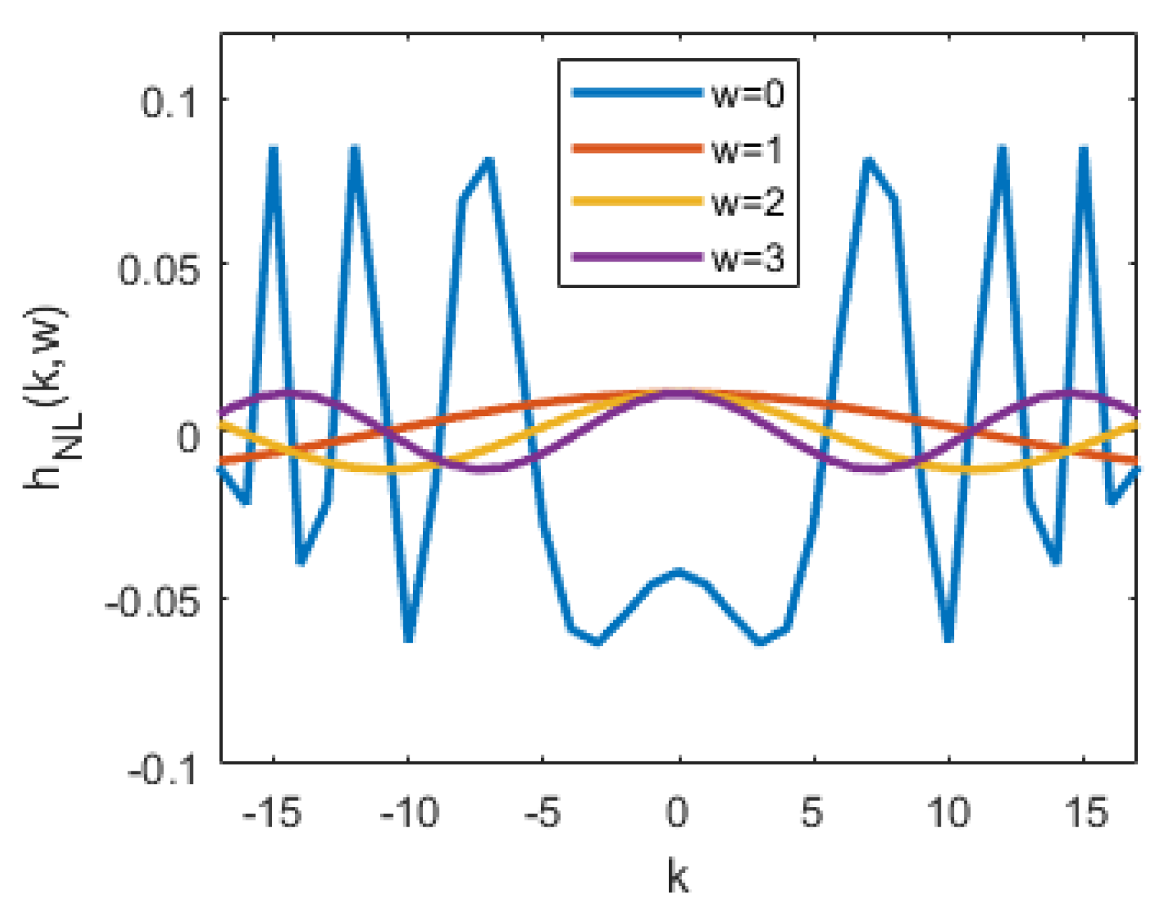
Figure 2.
Second-order Volterra kernel coefficients.
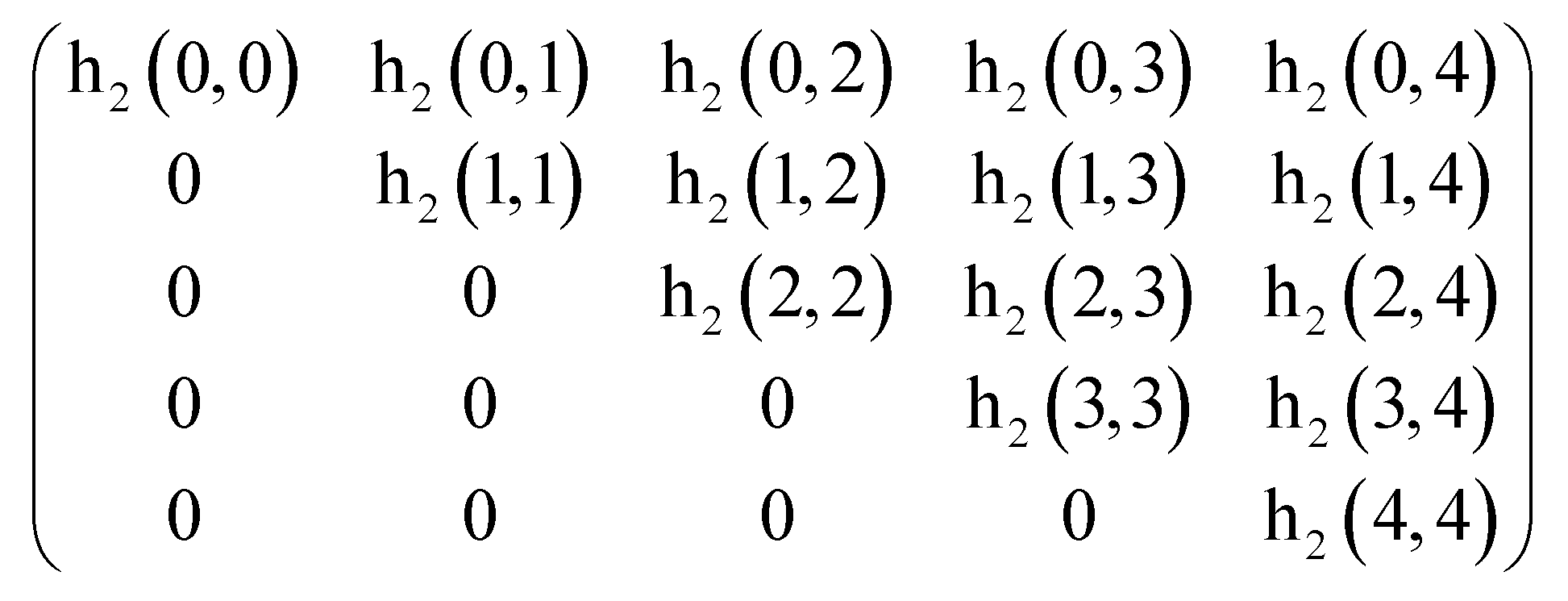
Figure 3.
Simplified Second-order Volterra kernel coefficients.
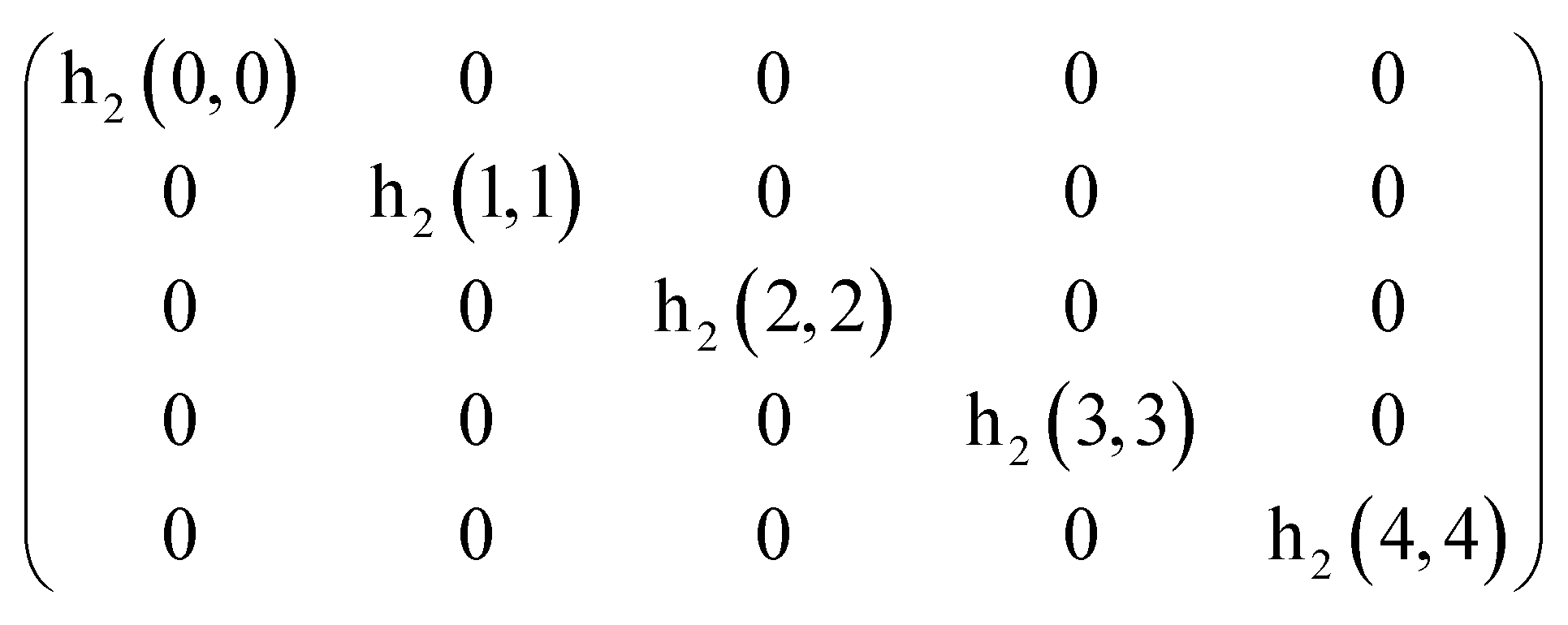
Figure 4.
Experiment Setup.
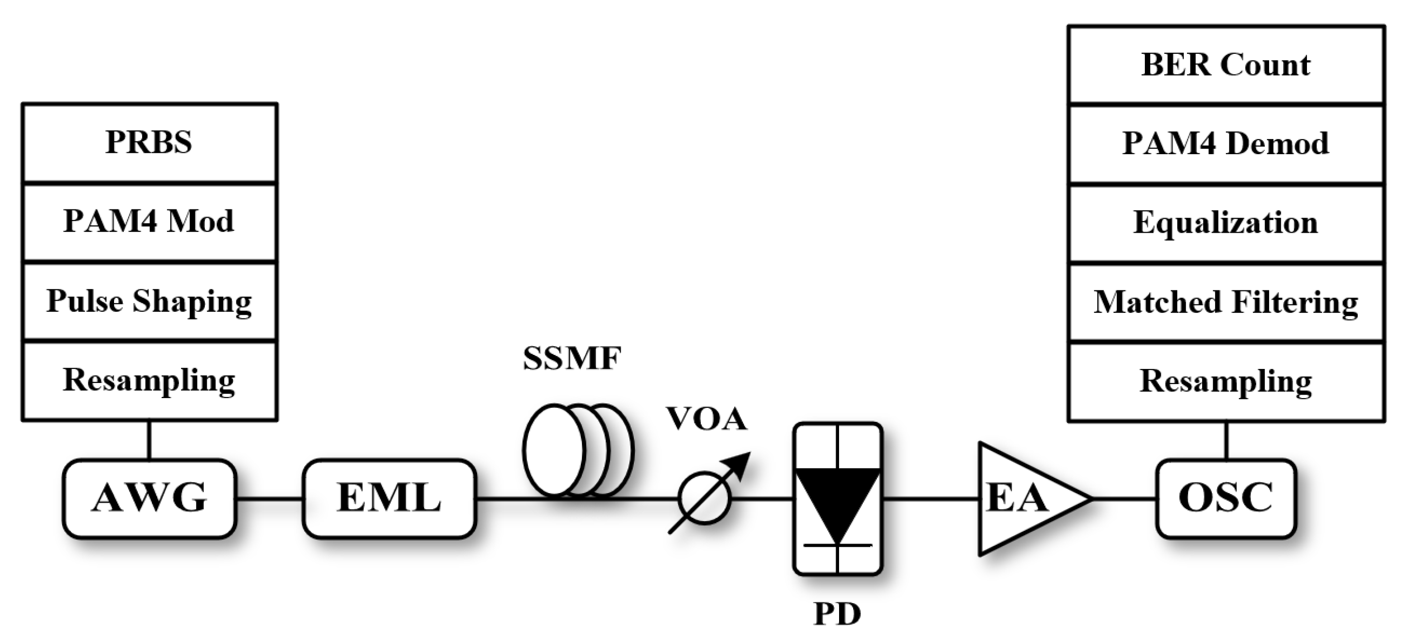
Figure 5.
BER Performance of 112Gbit/s PAM4 after B2B Transmission.
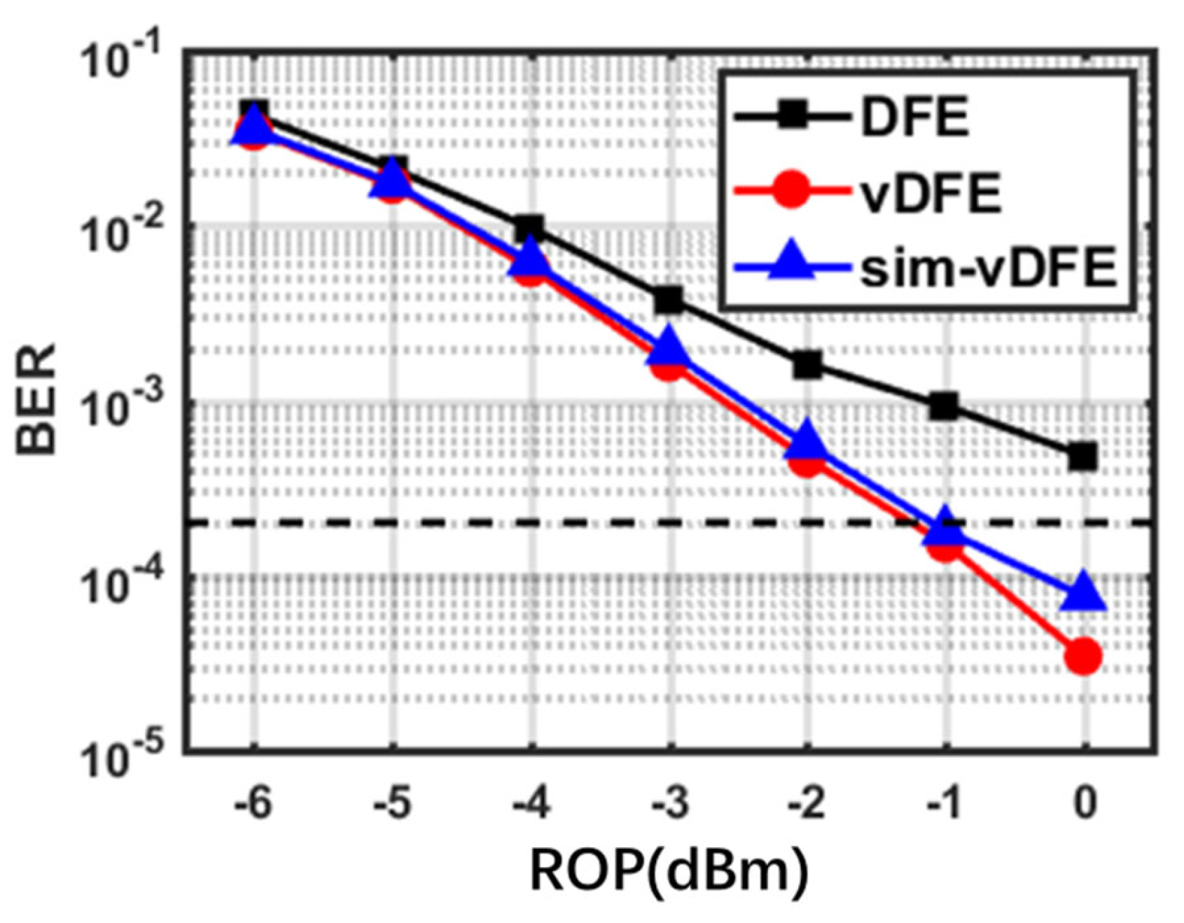
Figure 6.
BER Performance of 128Gbit/s PAM4 after B2B Transmission.
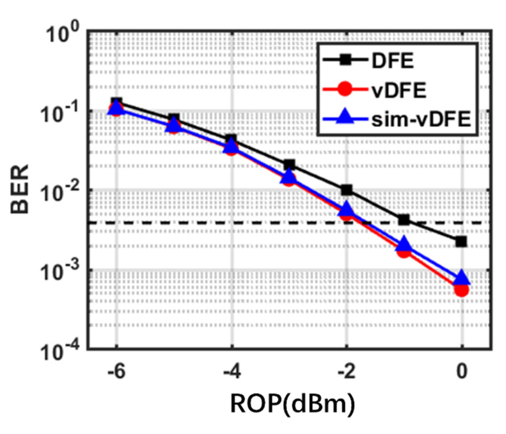
Figure 7.
BER Performance of 112Gbit/s PAM4 after 10km Transmission.
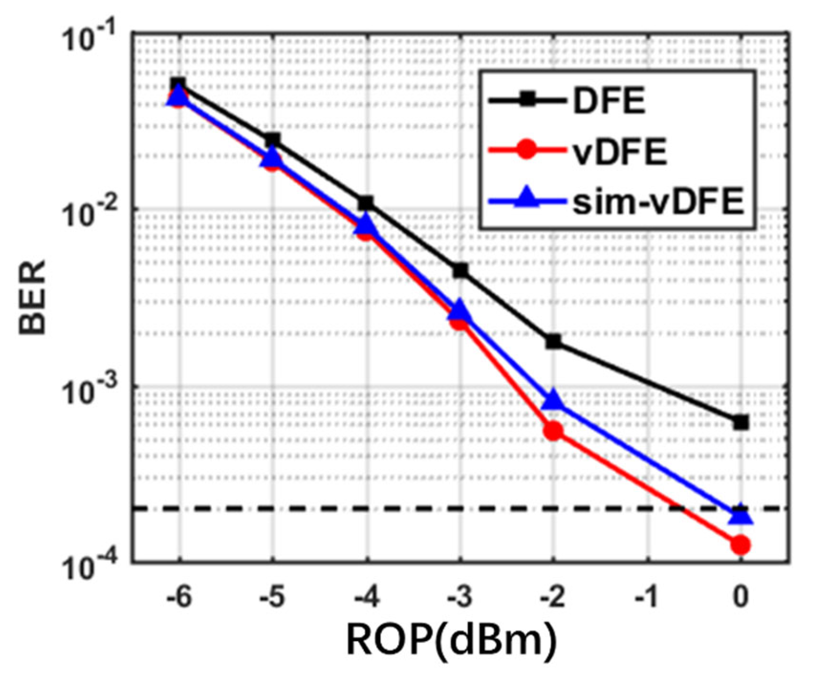
Figure 8.
BER Performance of 128Gbit/s PAM4 after 10km Transmission.
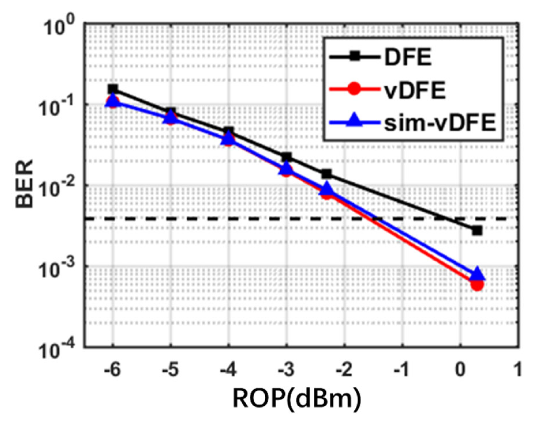

Table 1.
Equalizer complexity comparison.
| Equalizer | Taps | Multiplication |
|---|---|---|
| DFE | ||
| Volterra-DFE | ||
| Simplified Volterra-DFE |
Disclaimer/Publisher’s Note: The statements, opinions and data contained in all publications are solely those of the individual author(s) and contributor(s) and not of MDPI and/or the editor(s). MDPI and/or the editor(s) disclaim responsibility for any injury to people or property resulting from any ideas, methods, instructions or products referred to in the content. |
© 2023 by the authors. Licensee MDPI, Basel, Switzerland. This article is an open access article distributed under the terms and conditions of the Creative Commons Attribution (CC BY) license (http://creativecommons.org/licenses/by/4.0/).
Copyright: This open access article is published under a Creative Commons CC BY 4.0 license, which permit the free download, distribution, and reuse, provided that the author and preprint are cited in any reuse.


