Submitted:
05 June 2023
Posted:
06 June 2023
You are already at the latest version
Abstract
Background: There is a growing interest in TKA components alignment, especially around the kinematic technique, which aims at reestablishing the alignment of the native knee. However, the practical application of this technique has some limitations; (2) Methods: A series of consecutive full weight-bearing lower limbs radiographs performed in our Hospital without signs of osteoarthritis, post-traumatic deformities, and any previous surgical procedure (e.g. any joint replacement , osteotomy, anterior cruciate ligament reconstruction) were included. Several radiological parameters as the bisector line were measured by three members of our orthopedic unit and were then used to assess the inter-observer reliability.; (3) Results: 110 radiographic images belonging to 59 patients (both legs for 51 patients and one leg for 8 patients) were finally included in the present analysis. The bisector of the trochelar groove was perpendicular to the femoral joint line (mean 89.4°).; (4) Conclusions: The main finding of the current study was that the new anatomic landmark investigated, the bisector of the trochlear groove, was perpendicular to the femoral joint line viewed in the AP weight-bearing radiograph of the entire lower limbs of the healthy knee and therefore could potentially simplify the achievement of the kinematic alignment during a TKA procedure.
Keywords:
Knee
; alignment
; radiographs
; TKA
1. Introduction
Mechanical alignment has been historically used by orthopedic surgeons to implant prosthetic components in Total Knee Arthroplasty (TKA). In mechanically aligned TKA the distal femur and proximal tibia are cut perpendicularly to the femoral and tibial mechanical axes respectively to obtain a neutral 180° hip-knee-ankle angle (HKA) of the limb in the coronal plane [1]. The purpose of this alignment is to achieve a symmetric balanced load distribution between the medial and the lateral compartments to minimize wear and loosening [2,3]. However, the mechanical alignment of the component’s implants can alter the constitutional alignment of the limb and knee, because only a few limbs have a native neutral axis [4,5]. Although a mechanically aligned TKA improves the patient’s function, about 20% of patients are dissatisfied [6,7]. Furthermore, it may change knee kinematics due to variations in the physiological angles of the distal and posterior femoral condyles and tibial joint line. Changing joint lines alters the described tibiofemoral kinematics of the natural knee that occurs around two fixed axes [8,9,10]. For these reasons, a new kinematic alignment was introduced in TKA, with the aim of restoring more natural, not neutral, alignment to obtain a more natural knee kinematics and improve clinical results [11]. According to Kinematic studies of the natural knee, the posterior femoral condyles have a circular profile from 20° to 120° with a single radius of curvature and a single axis of rotation, the cylindrical axis, that is equidistant from the surface of both posterior femoral condyles [8,9,12,13]. Knee motion is described as rotations about fixed axes: knee flexion and extension around an axis fixed in the femur, the cylindrical or primary femoral axis; tibial internal and external rotation around a longitudinal axis fixed in the tibia, the longitudinal tibial axis; patella flexion and extension around an axis fixed in the femur, which is parallel, proximal and anterior to the primary femoral axis, i.e. the secondary femoral axis. The basic concept of kinematically aligned TKA is to restore the natural patient’s pre-arthritic joint lines. Therefore, it is fundamental to implant femoral component aligning its distal and posterior joint lines to the primary femoral axis of the knee [11,14]. The purpose of this study was to describe a new anatomical landmark for kinematically alignment of femoral component in TKA, the bisector of trochlear groove. The hypotheses were that the bisector is: 1) perpendicular to the femoral joint line and 2) parallel to the primary femoral axis. Therefore, performing the distal femoral cut perpendicular to this bisector allows the implantation of the femoral component aligned to the primary femoral axis, as proposed by kinematic alignment.
2. Materials and Methods
All consecutive full weight-bearing lower limbs radiographs in anteroposterior (AP) view performed in our Hospital between January 2021 and December 2022 were acquired from our digital repository. All patients had given their written consent for the use of anonymized data for scientific purpose. No ethical committee board approval was requested since the study was a radiographic study with no clinical data and all the imaging data were anonymized. Furthermore, no additional radiographic projections were required. The radiographic images in AP view of the entire lower limbs were in all cases taken with the knee in full extension with the patella facing forward, keeping the beam centered on the knee joint. The x-rays images were excluded from analysis if they presented signs of osteoarthritis, post-traumatic deformities, and any previous surgical procedure (e.g., any joint replacement, osteotomy, anterior cruciate ligament reconstruction). Furthermore, another exclusion creiterium was the incorrect limb rotation during x-ray acquisition. This was evaluated by checking the position of the patella and the profile of the lesser trochanter on the radiographic images. Once collected, the images were evaluated by three members of our orthopedic unit to assess the inter-observer reliability: one senior orthopedic surgeon (F.I.), one junior orthopedic surgeon (M.D.M.) and one orthopedic resident (A.I.). In addition, the same senior surgeon evaluated the same radiographic images at three different time points 2 weeks apart, to assess the intra-rater reliability. In each case, each investigator assessed the following parameters as described in the literature [15]: the hip-knee-ankle (HKA), which was expressed as a deviation from 180° with a negative value for varus and positive value for valgus alignment; the medial femoral mechanical angle (mFMA) and the mechanical medial tibial angle (mMTA) [15]. Then, the bisector of the trochlear groove (TGB) was defined as the bisector of the angle between two lines drawn from the radiographic apical midpoint of the intercondylar notch and tangential to the medial and lateral side of the radiographic notch respectively (Figure 1). The bisector angle (BA) was then defined as the medial angle between the TGB and the distal femur joint line.
The statistical analysis was performed with IBM SPSS version 25.0. The intra-rater, and inter-rater reliability analyses were based on the extended Bland and Altman plot and the intraclass correlation coefficient calculated by Two-way random effects, absolute agreement, multiple measurements/ raters. The extended Bland and Altman plot has on the axes the difference from the mean versus the mean of the raters (inter-raters) or the measurements (intra-raters) with limits of agreement of the mean for multiple observers and multiple measurements per observer [16]. The inter subjects Repeatability Coefficient (RC) was based on the algorithm according to Bland and Altman (1986) [16].
3. Results
110 radiographic images belonging to 59 patients (both legs for 51 patients and one leg for 8 patients) were finally included in the present analysis. The mean age of the included patients was 28.9 (range 19-38) and the male to female ratio was 37:22. The mean BA measurements performed by the three observers are summarized in Table 1, whereas the ones of the same observer at 3 different time points are presented in Table 2.
Regarding the other knee alignment parameters, the mean HKA was 180° (SD 2.48°), the mean mFMA was 92.4 (SD 1.88°) and the mTMA was 88 (SD 2.2°). Regarding the inter- observer analysis, the limits of agreement of the Extended Bland and Altman plot were ±1.3°, the intraclass correlation with two-way random effects model was 0.677 (95%CI 0.556-0.769) as shown in Figure 2.
For the intra- observer analysis, the limits of agreement of the Extended Bland and Altman plot were ±1.5°; the intraclass correlation at 3 time points with two-way random effects model was 0.823 (95% CI 0.757-0.873) as shown in Figure 3.
The Inter subject repeatability of ±2.5° is higher than the limit of agreement of the inter and intra observer analysis.
4. Discussion
The main finding of the current study is that the new anatomic landmark investigated, the bisector of the trochlear groove, is perpendicular to the femoral joint line viewed in the AP weight-bearing radiograph of the entire lower limbs of healthy knees. An additional finding is the high reproducibility of the measurement: indeed, among the three observers, an inter-reader agreement of 67.7% was found and among timely-spaced observations of the same observer an intra-reader agreement of 82.3%. Moreover, one of the three observer was a second-year resident, who clearly has not yet a trained eye for X-ray analysis, but nevertheless showed a good agreement with the other two senior observers. Furthermore, the inter-subject repeatability of ±2.5° is higher than the limit of agreement of the inter and intra observer analysis and it is quite small in general terms, meaning that the results have overall a little variability. This implies that not only the bisector of the trochlear groove is a potential new useful landmark for the knee alignment but is also an easily reproducible measurement. The mean measurements of the HKA, mFMA and the mTMA were in line with data reported in the literature [17]. Since the confidence interval was +/- 2° for all the 3 above-mentioned measurements, this variability in the limb alignment further confirms the theory of high heterogeneity in knee “physiological” alignment as described by Bellemans et al. [18]. Based on the data of current study, the trochlear bisector may be used for femoral distal cut in TKA according to kinematic alignment in patients affected by osteoarthritis. In fact, trochlear groove cartilage is usually less consumed by osteoarthritis since it is a non-weightbearing area and therefore the bisector of the trochlear groove is likely to remain unchanged through the years and therefore could be used as a potential landmark to restore the native pre-arthritic alignment during TKA procedure [19]. Employing the bisector of the trochlear groove as reference for the distal cut during surgery may restore the native pre-arthritic alignment as the kinematical alignment approach, thus avoiding any intra-operative error in the identification of the most worn side of the femur and avoiding relying on the assumption of 2 mm of cartilage consumption originally postulated by Howell when he firstly described the kinematic alignment technique [20]. The implant alignment may be calculated pre-operatively on standard full weight-bearing radiographs, as shown in Figure, 1 and then the femoral intramedullary guide can be easily set intra-operatively to match the pre-op planning, thus making this method fully appliable during surgery employing the standard surgical tools for TKA. Being this newly identified landmark easily identifiable and reproducible, it can streamline the implants positioning workflow and decrease the time required for implant alignment. This could potentially lead to shorter operating times, reduced anesthesia exposure for patients, and improved overall surgical efficiency. To measure this newly identified landmark we decided to employ the pre-operative radiographic images since it is the most common and the easiest tool in orthopedic practice. It is not the first time that the trochlear groove has been proposed as a useful tool for TKA alignment. Since the intercondylar notch is not considered to undergo pathological osteoarthritic changes, it has been recently described as a useful landmark for resection depth during the distal cut [21]. Nevertheless, according to the author knowledge, this work describes the first attempt in literature to employ the bisector of such trochlear groove to align the distal cut during a TKA procedure. Some limitations of the current study must be acknowledged: first, the fact that we performed our measures on patients without OA, which may have an impact on knee anatomy and therefore might potentially interfere with the measurement the bisector angle. Anyway, as stated above, this aspect should not play a relevant role since this region is usually poorly influenced by OA [19], secondly an intraoperative analysis is underway to observe if this landmark is preserved also in the arthritic knee. Another limitation is the absence of CT scans analysis, which might have strengthened our findings. A future study collecting CT data might provide stronger evidence to support this novel anatomical landmark for the distal femoral cut, even if acquiring CT scans of the hip-knee segment arises an ethical issue, since the exposure to significant number of radiations for research purposes might be questionable. Furthermore, CT scans are not routinely performed in patient’s candidate to TKA, so standard radiographs’ measurement is much easier to be implemented in routine clinical practice. Moreover, it is well documented in the literature the low reliability of lower limbs’ assessment on plain radiographic imaging given its two-dimensional nature; for example, for every 5° change in internal or external rotation of the lower limb a modification of 0.2° on the hip-knee-ankle angle was calculated [22]. We tried to overcome this limitation by standardizing the x-ray acquisition according to the guidelines described by Varatojo R. et al. [17]. Concerning the possible future development of this newly described alignment technique, until now the bisector of the trochlear grove was employed only to assist the distal cut during TKA surgery to determine the final varus-valgus alignment of the femoral component, however the introduction of a CT-based study in the preoperative planning could introduce an application of this landmark also in the definition of internal and external rotation and flexion-extension angle of the component. Moreover, if this newly introduced approach in TKA alignment will be proven effective by rigorous scientific evidence and validated through clinical studies, its application will be facilitated by robotic assisted surgery. Since these newly introduced robotic approaches have been found to improve the accuracy of implant positioning according to a precise pre-operative planning [23].
5. Conclusions
The current study provides a new radiographic reference system, i.e. the bisector angle, that could potentially simplify the achievement of the kinematic alignment during a TKA procedure. In accordance with our observations, this could be accomplished by per-forming the distal cut perpendicularly to the bisector of the trochlear groove, achieving a natural mFMA and positioning the femoral prosthetic component according to a kinematic alignment: an in-vivo surgical study is currently ongoing to verify whether the BA method is truly effective in achieving a kinematic alignment in patients undergoing TKA.
Author Contributions
Conceptualization, F.I. and M.M..; methodology, F.M.G. and T.B.; software, A.I and F.I. validation, M.M.; formal analysis, F.I.; investigation, F.M.G. A.I. and T.B.; resources, A.I and F.I..; data curation, A.I and F.I..; writing—original draft preparation, F.M.G. and F.I. writing—review and editing, B.D..; visualization, B.D.; supervision, M.M..; project administration, M.M. All authors have read and agreed to the published version of the manuscript.
Funding
This research was funded by the Italian Ministry of Health, grant number CO-2019-12370947”.
Institutional Review Board Statement
The study was conducted in accordance with the Declaration of Helsinki and approved on 30.03.2022 by the Institutional Review Board of Humanitas Research Hospital.
Informed Consent Statement
Informed consent was obtained from all subjects involved in the study.
Data Availability Statement
We are currently in the process of updating our database on Zenodo.
Conflicts of Interest
The authors declare no conflict of interest.
References
- Insall, J.; Scott, W.N.; Ranawat, C.S. The Total Condylar Knee Prosthesis. A Report of Two Hundred and Twenty Cases. J Bone Joint Surg Am 1979, 61, 173–180. [Google Scholar] [CrossRef] [PubMed]
- Berend, M.E.; Ritter, M.A.; Meding, J.B.; Faris, P.M.; Keating, E.M.; Redelman, R.; Faris, G.W.; Davis, K.E. Tibial Component Failure Mechanisms in Total Knee Arthroplasty. Clin. Orthop. Relat. Res. 2004, 26–34. [Google Scholar] [CrossRef]
- Ritter, M.A.; Faris, P.M.; Keating, E.M.; Meding, J.B. Postoperative Alignment of Total Knee Replacement. Its Effect on Survival. Clin Orthop Relat Res 1994, 153–156. [Google Scholar] [CrossRef]
- Eckhoff, D.G.; Dwyer, T.F.; Bach, J.M.; Spitzer, V.M.; Reinig, K.D. Three-Dimensional Morphology of the Distal Part of the Femur Viewed in Virtual Reality. J Bone Joint Surg Am 2001, 83-A Suppl 2, 43–50. [Google Scholar] [CrossRef] [PubMed]
- Luyckx, T.; Vanhoorebeeck, F.; Bellemans, J. Should We Aim at Undercorrection When Doing a Total Knee Arthroplasty? Knee Surg Sports Traumatol Arthrosc 2015, 23, 1706–1712. [Google Scholar] [CrossRef]
- Baker, P.N.; van der Meulen, J.H.; Lewsey, J.; Gregg, P.J.; National Joint Registry for England and Wales The Role of Pain and Function in Determining Patient Satisfaction after Total Knee Replacement. Data from the National Joint Registry for England and Wales. J Bone Joint Surg Br 2007, 89, 893–900. [Google Scholar] [CrossRef] [PubMed]
- Bourne, R.B.; Chesworth, B.M.; Davis, A.M.; Mahomed, N.N.; Charron, K.D.J. Patient Satisfaction after Total Knee Arthroplasty: Who Is Satisfied and Who Is Not? Clin Orthop Relat Res 2010, 468, 57–63. [Google Scholar] [CrossRef]
- Churchill, D.L.; Incavo, S.J.; Johnson, C.C.; Beynnon, B.D. The Transepicondylar Axis Approximates the Optimal Flexion Axis of the Knee. Clin Orthop Relat Res 1998, 111–118. [Google Scholar] [CrossRef]
- Eckhoff, D.; Hogan, C.; DiMatteo, L.; Robinson, M.; Bach, J. Difference between the Epicondylar and Cylindrical Axis of the Knee. Clin Orthop Relat Res 2007, 461, 238–244. [Google Scholar] [CrossRef]
- Hollister, A.M.; Jatana, S.; Singh, A.K.; Sullivan, W.W.; Lupichuk, A.G. The Axes of Rotation of the Knee. Clin Orthop Relat Res 1993, 259–268. [Google Scholar] [CrossRef]
- Nisar, S.; Palan, J.; Rivière, C.; Emerton, M.; Pandit, H. Kinematic Alignment in Total Knee Arthroplasty. EFORT Open Rev 2020, 5, 380–390. [Google Scholar] [CrossRef]
- Coughlin, K.M.; Incavo, S.J.; Churchill, D.L.; Beynnon, B.D. Tibial Axis and Patellar Position Relative to the Femoral Epicondylar Axis during Squatting. J Arthroplasty 2003, 18, 1048–1055. [Google Scholar] [CrossRef]
- Elias, S.G.; Freeman, M.A.; Gokcay, E.I. A Correlative Study of the Geometry and Anatomy of the Distal Femur. Clin Orthop Relat Res 1990, 98–103. [Google Scholar] [CrossRef]
- Howell, R.; Kumar, N.S.; Patel, N.; Tom, J. Degenerative Meniscus: Pathogenesis, Diagnosis, and Treatment Options. World J Orthop 2014, 5, 597–602. [Google Scholar] [CrossRef]
- Marques Luís, N.; Varatojo, R. Radiological Assessment of Lower Limb Alignment. EFORT Open Rev 2021, 6, 487–494. [Google Scholar] [CrossRef]
- Christensen, H.S.; Borgbjerg, J.; Børty, L.; Bøgsted, M. On Jones et al.’s Method for Extending Bland-Altman Plots to Limits of Agreement with the Mean for Multiple Observers. BMC Medical Research Methodology 2020, 20, 304. [Google Scholar] [CrossRef]
- Luís, N.M.; Varatojo, R. Radiological Assessment of Lower Limb Alignment. EFORT Open Reviews 2021, 6, 487–494. [Google Scholar] [CrossRef] [PubMed]
- Bellemans, J.; Colyn, W.; Vandenneucker, H.; Victor, J. The Chitranjan Ranawat Award: Is Neutral Mechanical Alignment Normal for All Patients? The Concept of Constitutional Varus. Clin Orthop Relat Res 2012, 470, 45–53. [Google Scholar] [CrossRef]
- Mullaji, A.B.; Padmanabhan, V.; Jindal, G. Total Knee Arthroplasty for Profound Varus Deformity: Technique and Radiological Results in 173 Knees with Varus of More than 20 Degrees. J Arthroplasty 2005, 20, 550–561. [Google Scholar] [CrossRef] [PubMed]
- Howell, S.M.; Howell, S.J.; Kuznik, K.T.; Cohen, J.; Hull, M.L. Does A Kinematically Aligned Total Knee Arthroplasty Restore Function Without Failure Regardless of Alignment Category? Clinical Orthopaedics and Related Research 2013, 471, 1000. [Google Scholar] [CrossRef] [PubMed]
- Liu, D.W.; Martinez Martos, S.; Dai, Y.; Beller, E.M. The Femoral Intercondylar Notch Is an Accurate Landmark for the Resection Depth of the Distal Femur in Total Knee Arthroplasty. Knee Surg Relat Res 2022, 34, 32. [Google Scholar] [CrossRef] [PubMed]
- Oswald, M.H.; Jakob, R.P.; Schneider, E.; Hoogewoud, H.M. Radiological Analysis of Normal Axial Alignment of Femur and Tibia in View of Total Knee Arthroplasty. J Arthroplasty 1993, 8, 419–426. [Google Scholar] [CrossRef] [PubMed]
- Kayani, B.; Konan, S.; Ayuob, A.; Onochie, E.; Al-Jabri, T.; Haddad, F.S. Robotic Technology in Total Knee Arthroplasty: A Systematic Review. EFORT Open Reviews 2019, 4, 611–617. [Google Scholar] [CrossRef] [PubMed]
Figure 1.
Weight-bearing x-ray AP view of a 31-years old female. Section A represents the original acquisition. Section B represents a zoomed version of section A and shows how the bisector of the trochlear groove (green line) was identified. In section C is shown the bisector angle (BA), defined as the angle between the bisector of the trochlear groove (measured in section B) and the joint line of the distal femur.
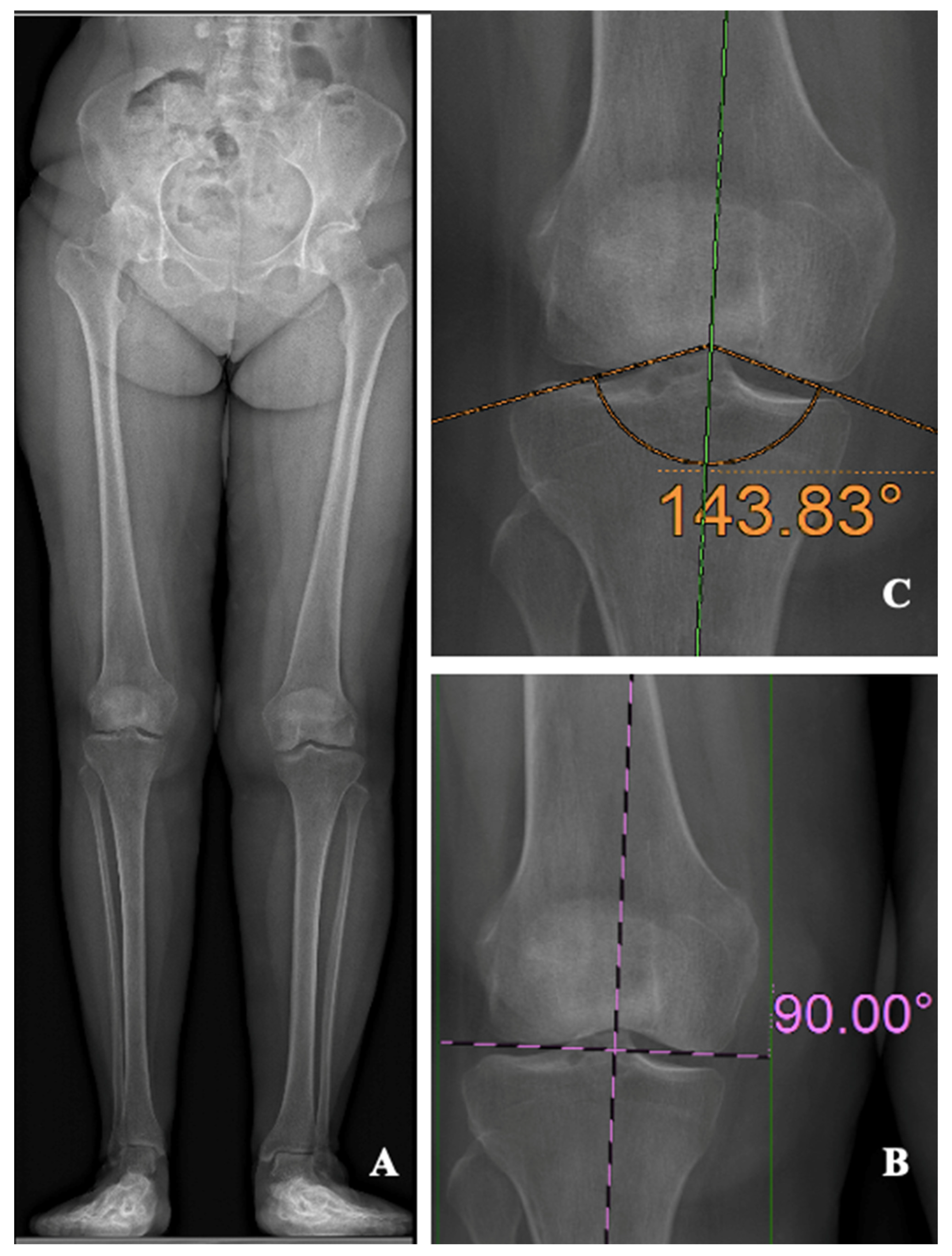
Figure 2.
Extended Bland and Altman plot for the inter-observers agreement.
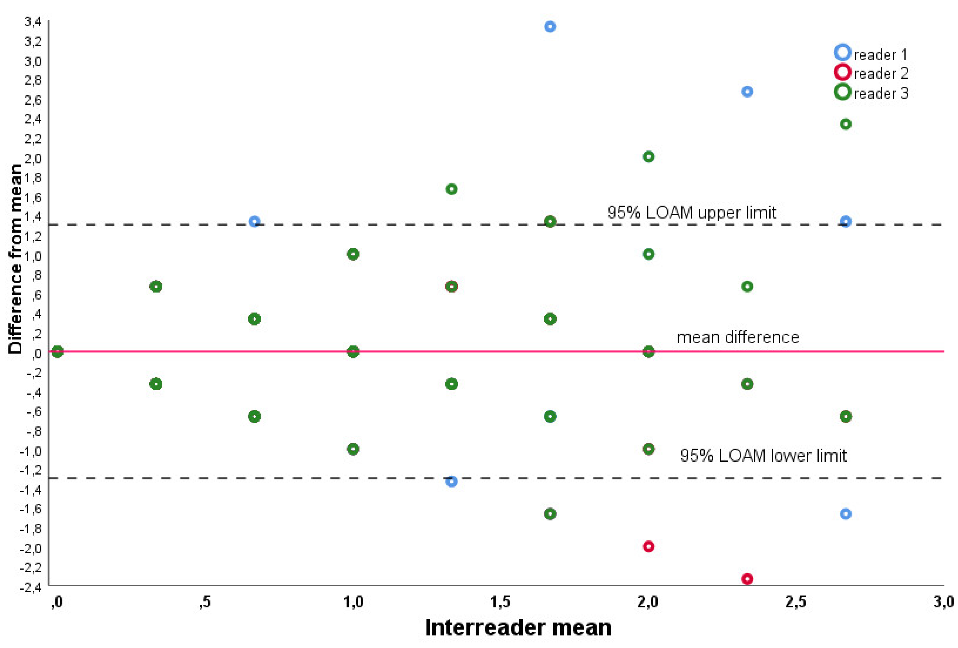
Figure 3.
Extended Bland and Altman plot for the intra-observer agreement. .
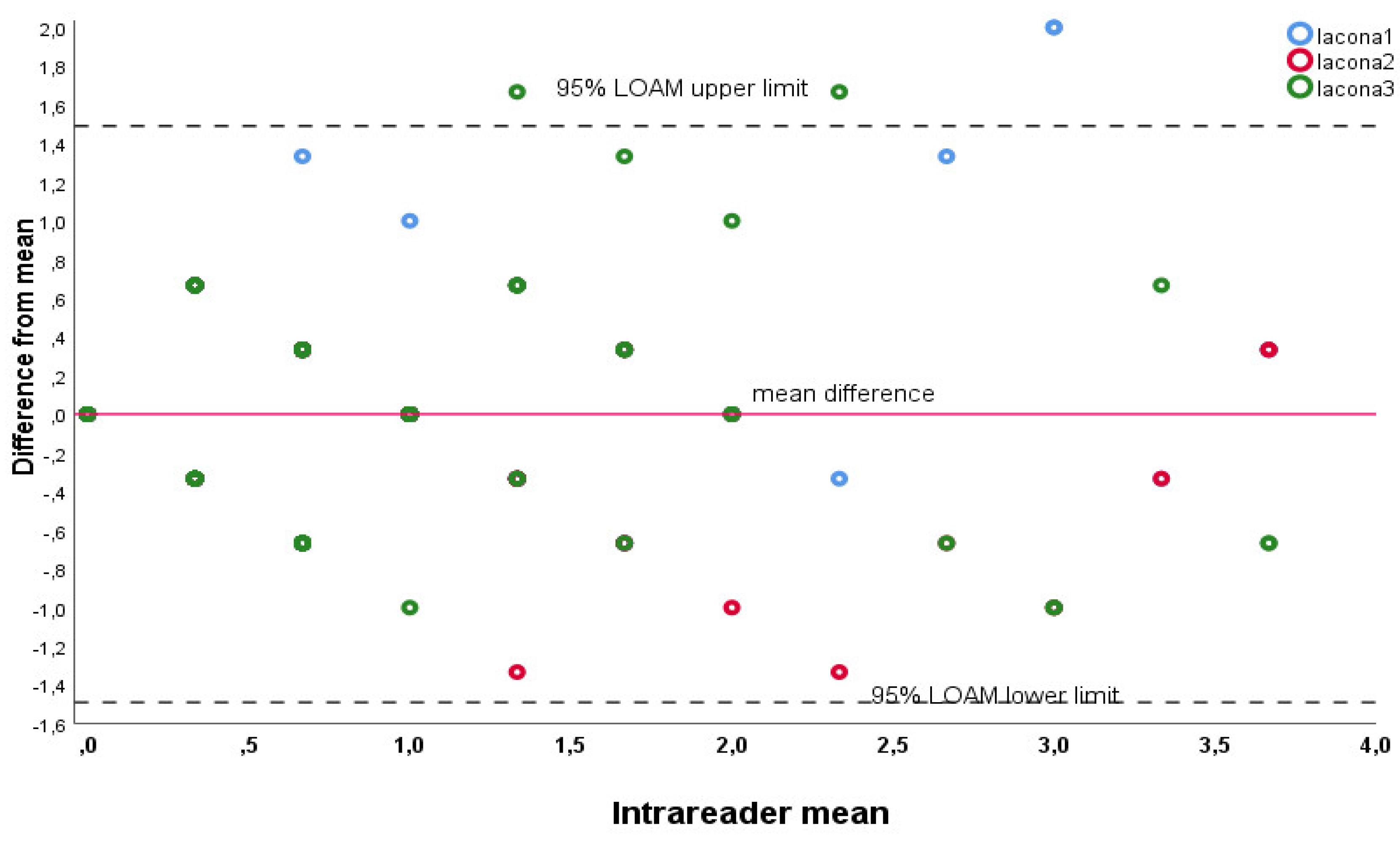

Table 1.
Mean BA values obtained by the 3 observers. Legend: BA = Bisector angle, SD = standard deviation.
Table 1.
Mean BA values obtained by the 3 observers. Legend: BA = Bisector angle, SD = standard deviation.
| Observer 1 | Observer 2 | Observer 3 | |
|---|---|---|---|
| BA (SD) | 89.5° (±1.25) | 89.3 (± 0.96) | 89.2 (± 1.1) |
Table 2.
BA values obtained at 3 different time points (each 2 weeks apart) by the senior observer. Legend: BA = Bisector angle, SD = standard deviation.
Table 2.
BA values obtained at 3 different time points (each 2 weeks apart) by the senior observer. Legend: BA = Bisector angle, SD = standard deviation.
| Observer 1- time 1 | Observer 1- time 2 | Observer 1- time 3 | |
|---|---|---|---|
| BA (SD) | 89.6° (± 1) | 89.5 (± 0.96) | 89.5 (± 1.1) |
Disclaimer/Publisher’s Note: The statements, opinions and data contained in all publications are solely those of the individual author(s) and contributor(s) and not of MDPI and/or the editor(s). MDPI and/or the editor(s) disclaim responsibility for any injury to people or property resulting from any ideas, methods, instructions or products referred to in the content. |
© 2023 by the authors. Licensee MDPI, Basel, Switzerland. This article is an open access article distributed under the terms and conditions of the Creative Commons Attribution (CC BY) license (http://creativecommons.org/licenses/by/4.0/).
Copyright: This open access article is published under a Creative Commons CC BY 4.0 license, which permit the free download, distribution, and reuse, provided that the author and preprint are cited in any reuse.


