1. Introduction
The engagement of the arresting hook with the arresting cable is a precise maneuver that requires coordination and timing between the pilot and the deck crew. The aircraft must approach the cable at the correct angle and speed to ensure that the hook engages the cable properly[
1]. The primary focus in the study of aircraft carrier-based landing dynamics is whether the arresting hook can engage the arresting cable, as well as the loads experienced by the arresting hook and the stress conditions on its structure.
Due to the complexity of aircraft carrier arresting systems and the unique operational environment, it is challenging to accurately measure real-time loads during experiments. Moreover, conducting such experiments poses significant difficulties and risks[2-5]. During the development stage of carrier-based aircraft, the primary technical approach currently employed is to analyze the fundamental landing performance through theoretical analysis and simulation methods. This analysis is then integrated with the actual operational environment to facilitate appropriate optimization and design.
Thomlinson[
6] conducted a research on the motion of the aircraft arresting hook within the plane of symmetry after impacting the deck. In the paper, it was assumed that the carrier-based aircraft has no yaw deviation during the arresting process. By analyzing the mechanical relationships among the aircraft, the deck, and the arresting hook, a set of motion differential equations was established. Jones[
7] obtained a fitting equation and curve for the arresting force based on statistical data from the arresting system. Zhu[
8] considered the influence of frictional forces on the collision between the arresting hook and the deck, and established a more accurate model for the arresting hook and deck collision. The enhanced model provides a better understanding of the dynamics and interaction between the arresting hook and the deck during the collision process. The researches extends Thomlinson's work by incorporating collision theory for theoretical calculations. However, it is acknowledged that the model assumptions in these studies are idealized making it difficult to accurately reflect the actual conditions during aircraft landing.
The aircraft landing arresting process involves multiple dynamic processes, such as the collision rebound of the arresting hook and the engagement of the hook with the arresting cable. These complexities pose challenges to the research on the safety of aircraft landing arresting. Research in this field employs the construction of virtual prototype models of the aircraft arresting system to achieve accurate prediction and analysis of the arresting process. Multibody dynamics software can be used to perform simulations for the performance analysis of aircraft landing and arrest[
9].
Deng[
10] developed a 2D non-material variable-domain co-rotational element to perform a nonlinear dynamic analysis of arresting gears, and the nonlinear equation of the hydraulic damper subsystem is formulated. The propagation mechanism of longitudinal waves and kink waves is investigated. Shen[
11] established a full-scale dynamic model of MK7 type arresting gear system based on multi-body dynamics method. Zhang[
12] adopted Arbitrary Lagrangian Eulerian formulation to efficiently simulate the hook/pulley-cable moving contact in arresting cable systems. Zhang[
13] developed a dynamic model for the rebound of the arresting hook during collision, using a numerical iterative approach to obtain the longitudinal safety envelope of the aircraft during landing and arresting process. However, it is important to note that this approach is predicated upon a set of assumptions and simplifications, thereby imposing limitations on its capacity to accurately depict the intricate stress-strain dynamics inherent in the hook and cable engagement during the arresting process. As a result, the applicability of the model is limited. Peng[
14] conducted an impact rebound test for the arresting hook and subsequently refined the coefficient of restitution for the deck coating based on the test results. By incorporating Hertz contact theory, a more precise simulation model was established.
The precise analysis of the arresting hook engaging cable process requires a holistic examination encompassing the effects of landing gear shock absorbers, flexible tires, as well as the geometric dimensions and mechanical characteristics of the arresting cable and hook. In this paper, an high accurate dynamic model of the arresting engagement is established. A dynamic model of the landing gear tires, arresting cable, and pulley assembly, as well as the arresting hook, is established using the FEM-MBD method. Considering the effect of aerodynamic load and engine thrust, the research presented aims to rigid-flexible coupling dynamic modeling method of the hook engagement process during the arresting process. The dynamic model was verified through a comparison between simulation results and experiment obtained from reference. The simulation model accurately captures the process of aircraft hook engagement, including the rebound motion of the hook upon deck impact, the oscillations of the cable during the engagement process, and the stress distribution on the arresting hook.
2. Dynamic model of carrier-based aircraft landing and engage with cable
2.1. Interactions between elements
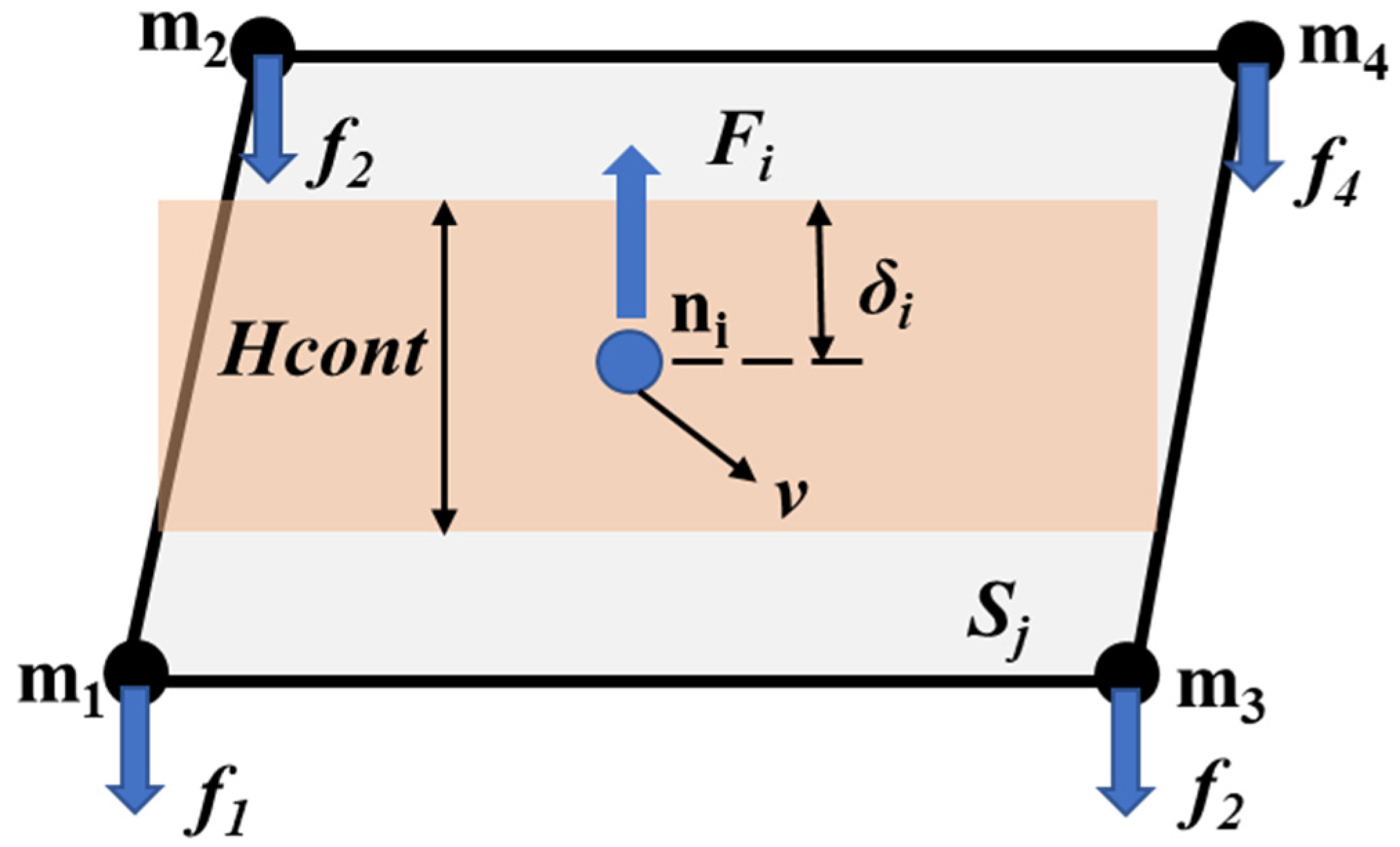
The finite element method employs primarily 8-node hexahedral elements and 4-node shell elements to describe the structural components. The contact force model between elements is illustrated in
Figure 1.
represents the slave node,
represents the master surface,
represents the master surface node,
represents contact thickness,
represents the penetration between elements,
represents relative sliding velocity at the contact point with respect to the master surface,
represents the contact force acting on the slave node
,
represents the equivalent force acting on the master node.
The interaction forces
between elements can be resolved into the normal component
and tangential component
, which are determined by Equations (1)-(3).
where,
is the normal elastic force,
is the normal viscous force,
is the tangential elastic,
is the coefficient of friction,
is the unit vector in the normal direction of contact,
is the unit vector in the tangential direction of contact.
The nonlinear normal elastic force
and normal viscous force
between elements are given by Equations (4) and (5) respectively.
where
is the local contact stiffness,
is proportionality factor of contract force,
is the internal damping, and
is the contact damping coefficient,
is the mass of slave node,
is the relative velocity in the normal direction at the contact point.
The tangential elastic force
and tangential friction force
between elements are as follows.
where
is the tangential stiffness,
is the tangential relative displacement,
is Poisson's ratio,
is the tangential relative velocity.
2.2. Dynamic model of a carrier-based aircraft
In the research, the deformation and stress of the arrested aircraft frame is not the main concern. Therefore, it is modeled using rigid bodies. Notice that a common technique to simplify system dynamic equations and reduce computational costs is adopted in this paper, where multiple rigid bodies are connected through fixed joints.
The aircraft is modeled by a fuselage rigid body and other elastic parts.
2.1.1. Configuration of aircraft
The dynamic model in this paper consists of the arresting hook, nose landing gear(NLG), main landing gear(MLG) and fuselage as shown in
Figure 2. Aerodynamic forces are applied as 6 degree-of-freedom load on the rigid fuselage, with the point of application converted to the center of gravity. The influence of engine rotational torque is neglected, and the engine thrust is decoupled into three-axis force acting at a point inside the rigid body of aircraft. The relative positions of aerodynamic forces and thrust with respect to the aircraft body are depicted in
Figure 2(b).
2.1.2. Dynamic model of landing gear
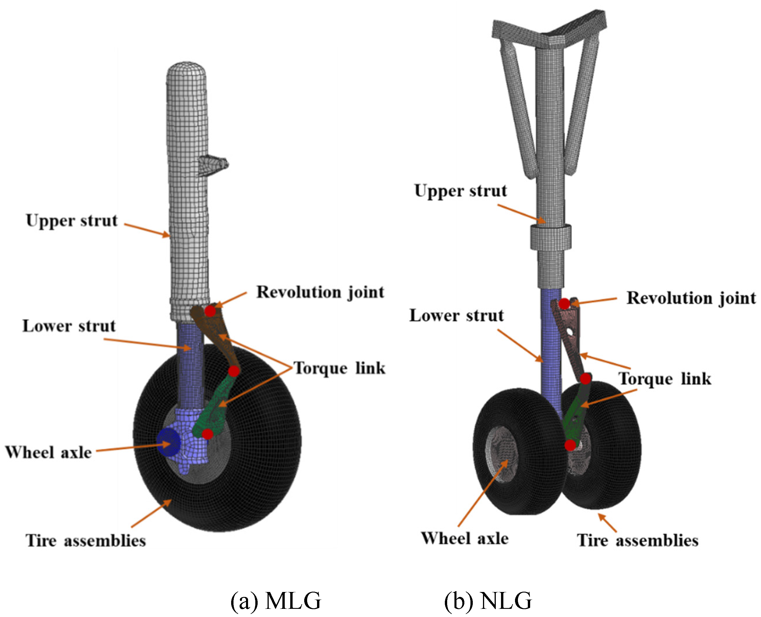
The landing gear is the ground support system of aircraft and plays a crucial role as an energy-absorbing component during the landing process. As shown in
Figure 3, the dynamic model of landing gear consists of upper strut, lower strut, torque link, wheel axle and tire assemblies.
The displacement of the shock absorber is determined by relative motion of the upper and lower struts. The hydraulic force
can be expressed as
where
is the air spring force,
is the hydraulic damping force.
The air spring force
can be represented as
where
is the initial pressure area of the low-pressure air chamber.,
is the pressure area of the high-pressure air chamber,
is the initial pressure in the low-pressure air chamber.
is the initial pressure in the low-pressure air chamber.
is the atmospheric pressure,
is the stroke of the damper,
is the initial stroke of the high-pressure chamber.
is the initial volume of the low-pressure chamber,
is the initial volume of the high-pressure chamber,,
is the polytropic exponent.
The air spring force is different between the low-pressure chamber and the high-pressure chamber. When compression occurs within the low-pressure chamber, only the air spring force generated by the low-pressure chamber absorbs energy. However, when the compression stroke reaches the initial stroke of the high-pressure chamber, both the high-pressure and low-pressure chambers generate air spring forces that simultaneously contribute to the absorption of energy. The hydraulic damping force can be expressed as follows,
where
is the oil density,
is stroke velocity,
is the effective area of the buffer,
is the main oil cavity oil hole area,
and
are the flow coefficient of main oil hole at forward and reverse stroke,
is the effective area of the back oil hole,
and
are effective flow area of oil return hole at compression and reverse stroke,
and
are flow coefficient of back oil hole at compression and reverse stroke.
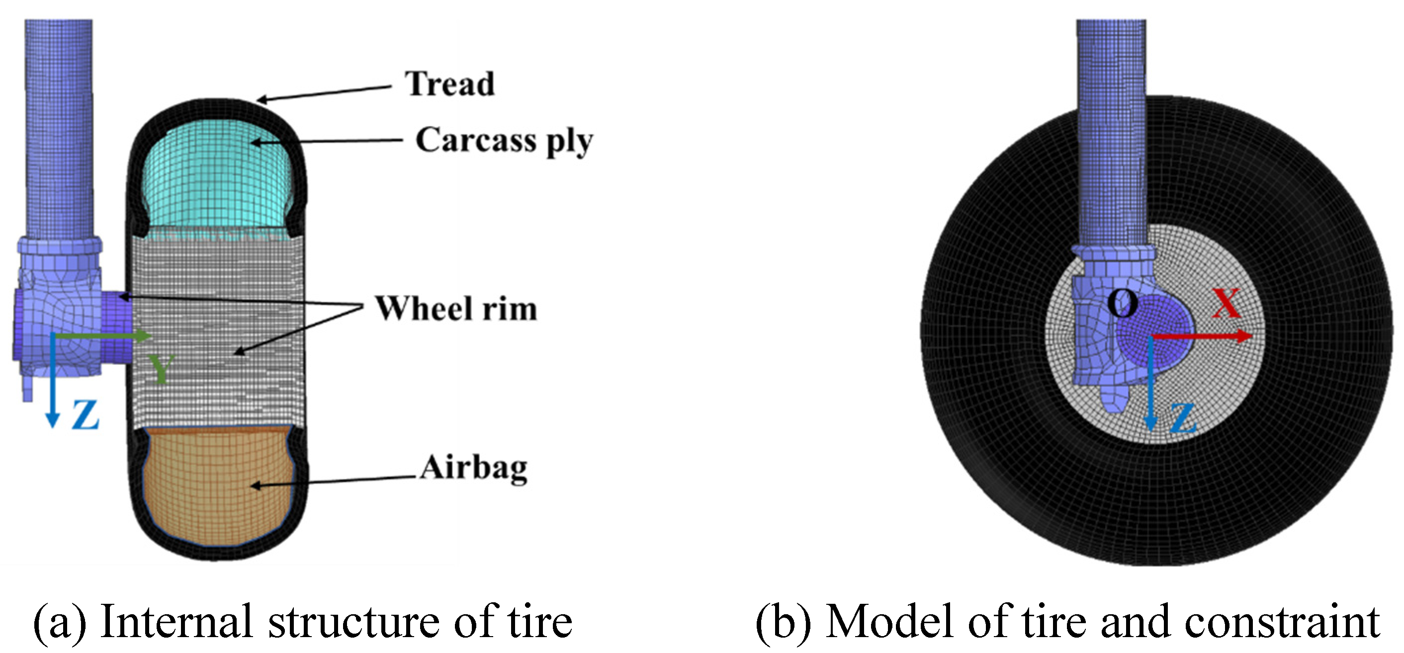
In addition to the load of shock absorber, the flexibility of the tire also contributes significantly to the impact load during aircraft landing. The compression of tire under impact load is a significant proportion of the overall compression stroke of the landing gear damping system. The internal structure of the tire is depicted in
Figure 4(a), where the inner layer of the tire is defined as the fabric material and the volume surrounded by the wheel rim and the inner fabric layer of the tire is filled with gas.
The tread and the wheel rim share common nodes on the adjacent surface, and the rotational constraints of the tire are defined using a coordinate system O-XYZ located at the center of the wheel rim as shown in
Figure 4(a). The rubber material of the tire is modeled using 8-node hexahedral elements, employing the Mooney-Rivlin material model. The constitutive equation for this model is given by
where
,
, A and B is the Rivlin constants determined through uniaxial tensile testing.
is the Poisson's ratio,
,
and
Green-Lagrange strain tensor constants.
2.1.3. Arresting hook
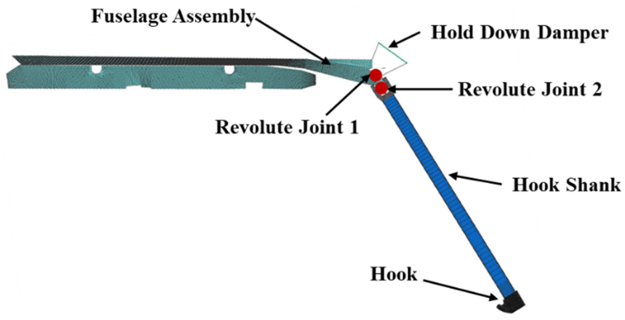
The dynamic model of arresting hook is shown in
Figure 5. Dynamic model of arresting hook contains fuselage assembly, hold down damper, hook shank, hook and two revolute joint. By defining revolute joints 1 and 2, the longitudinal and transverse rotations of the arresting hook are respectively determined.
Prior to engaging the arresting cable, the arresting hook collide with the deck and rebound with a certain velocity. The rebound height of the arresting hook is limited by the hold down damper to ensure successful engagement of the arresting hook with cable. Therefore, the hold down damper of the arresting hook plays a critical role in determining the height of the rebound [
12].
2.3. Dynamic model of arresting system
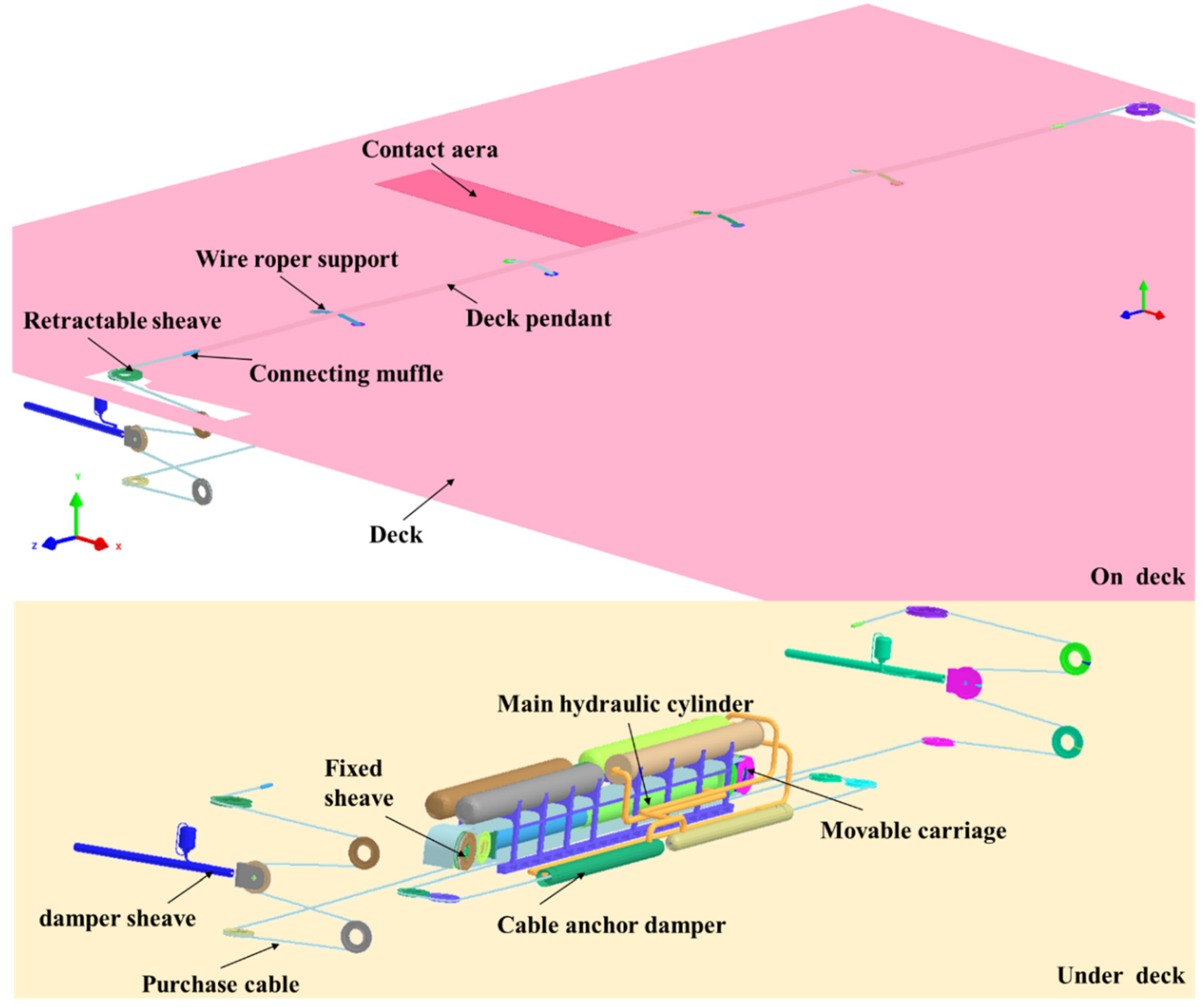
The simulation model of arresting system is composed of deck, wire roper support and arresting gear system. The deck is divided into arresting hook contact area and non-contact area as shown in
Figure 6. And the arresting gear system in this paper is based on the MK7-3 hydraulic arresting gear system[
5]. The entire hydraulic arresting gear system model is divided into three components: the pulley system, the hydraulic system and arresting cable system. The pulley system consists of fixed pulleys, moving pulleys, and steering pulleys. The hydraulic system is composed of damper sheave, main hydraulic cylinder and cable anchor damper system, which are modeled by shell element and spring-damper beam. In our research, the deformation and stress of pulley, piston and cylinder system are not the main concern. Therefore, they are modeled using rigid bodies.
2.2.1. Modeling of rigid bodies in the arresting cable system and constraints
The arresting hook of a carrier-based aircraft engages with the arresting cable, resulting in the cable being pulled out during the arresting process. The cable is threaded through the arresting gear system that are forming a block-and-tackle mechanism. This mechanism is designed to transfer the load from the aircraft to the hydraulic machine. Within the hydraulic machine, the kinetic energy of the aircraft is converted into heat and subsequently dissipated.
The arresting gear system is a complicated mechanical-hydraulic system. In this paper, the arresting gear system is modeled using three arresting cables (one deck pendant and two purchase cables), block and tackles (48 sheaves), and five hydraulic dampers (two damper sheave installations, two cable anchor dampers, and one hydraulic cylinder). The fixed sheave assembly is merged into the deck, which avoids unnecessary fixed joints between the deck and itself. Consider other rigid body shown in
Figure 6, which undergoes translation and rotation simultaneously.
2.2.2. Arresting cable
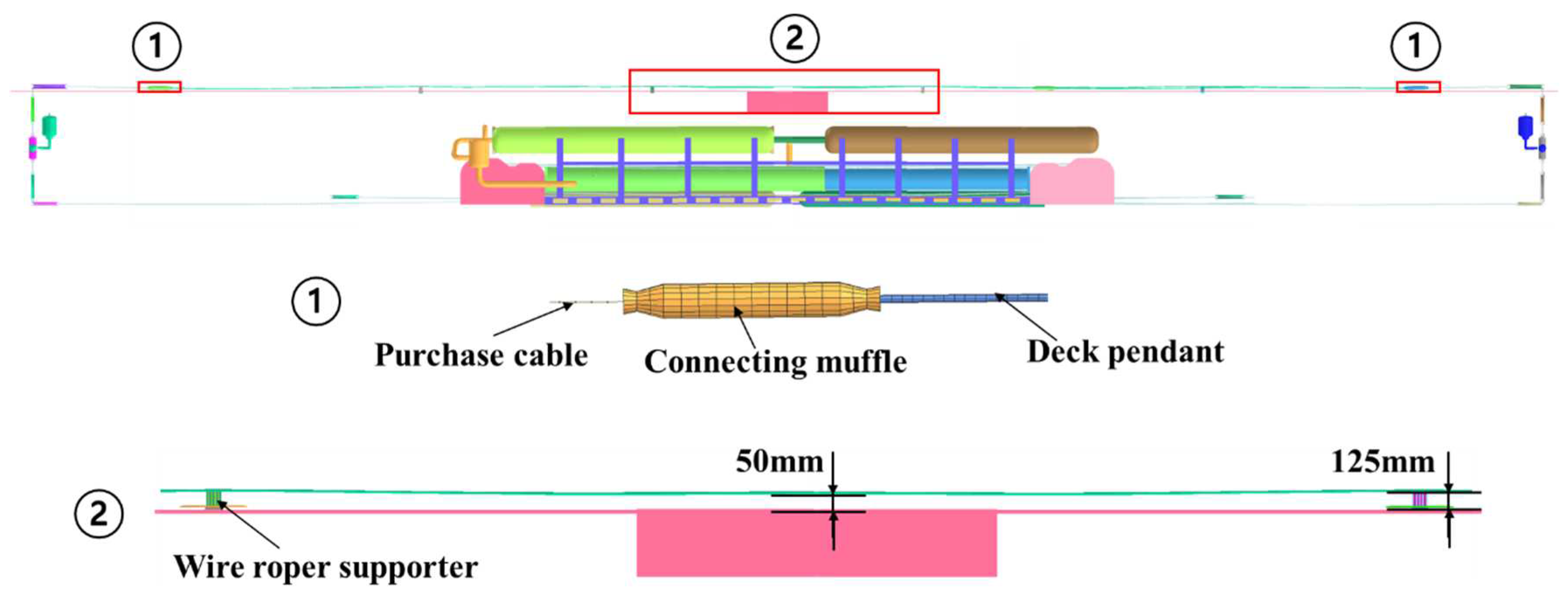
The configuration of pendant and wire roper support is shown in
Figure 7. To improve computational efficiency, the arresting cable is divided into two parts based on the connecting muffle: the pendant and the purchase cable as shown in
Figure 7. The purchase cable is modeled using a nonlinear tension bar. This modeling approach considers the nonlinear dynamic characteristic of the cable under tension by accounting for factors such as material properties, cable diameter and applied tension forces. The pendant is modeled using a 6 degree of freedom(DOF) spring beam. The model accounts for translational and rotational motions of cable, allowing for a more detailed analysis of its dynamic behavior during aircraft arrestment.
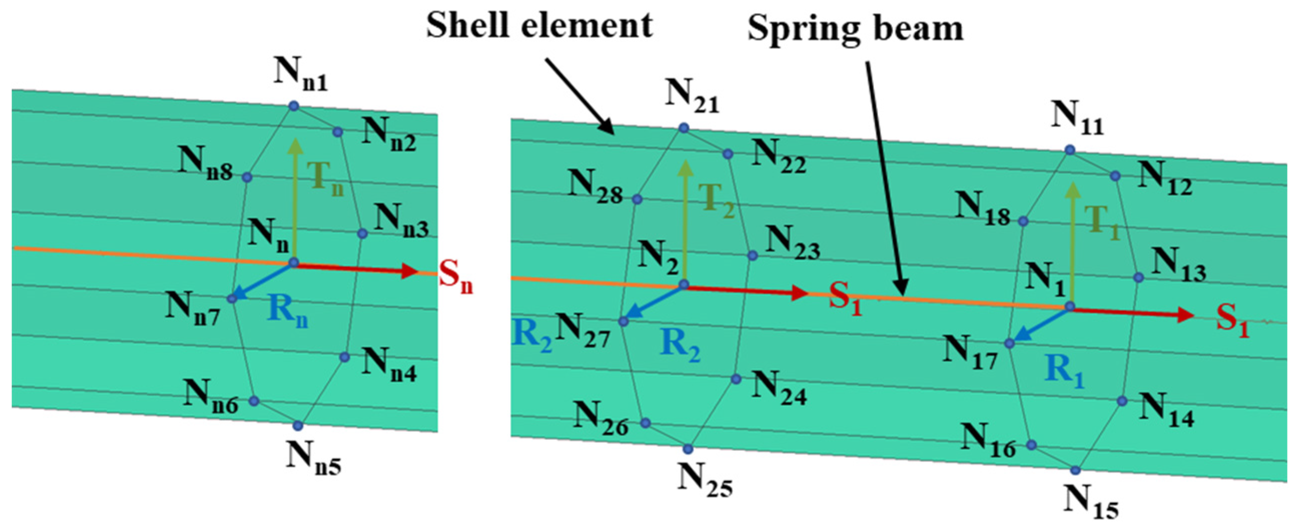
The dynamic model of pendant is modeled by shell and spring beam element with 6 DOF as shown in
Figure 8. The beam element is connected to the shell element at the nodes N
i and the nodes N
i1-N
i8 of the shell element. These nodes collectively form a rigid body. In the local coordinate system (N
i-S
iR
iT
i), N
i represents the origin point of the coordinate system, S
i denotes the direction vector along the beam axis, R
i represents the direction vector along the cross-sectional plane of the beam, and T
i represents the direction vector perpendicular to both R
i and S
i. By defining the constitutive characteristics of beam in the local coordinate system, it allows for an accurate representation of the beam's deformation and response to applied loads. This approach facilitates the analysis and simulation of the beam element within the larger structural system.
2.2.3. Wire roper supports
The wire supports serve as a means of elevating the cable above deck to guarantee the engagement of the arresting cable on the incoming arresting hook. The four wire supports are equidistant across the deck, and maintain a cross-deck cable height of 0.5 meter minimum, measured from the bottom of the cable to deck at its lowest point (
Figure 7). Each wire roper support is mounted directly to the deck[
16].
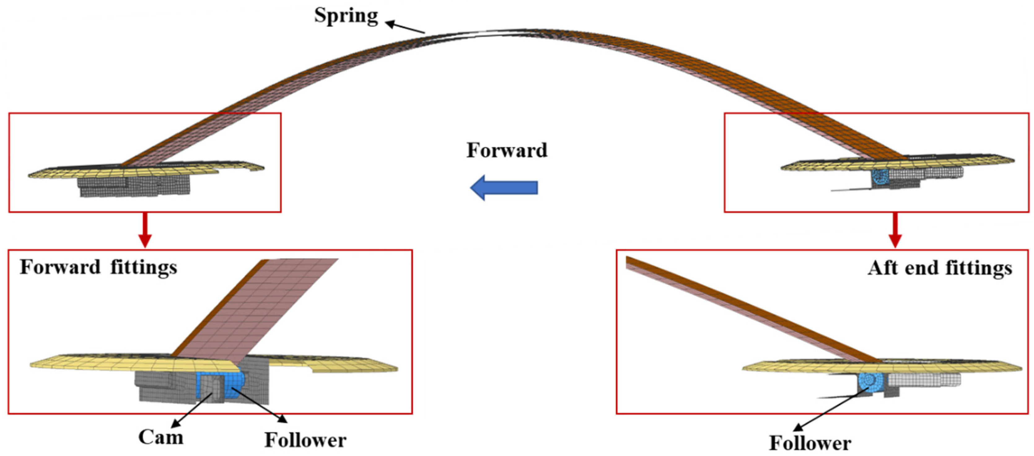
As shown in
Figure 9, the model of the wire support is established in this paper based on 4 node shell element. The forward end of the wire support spring is rigidly secured by use of a cam mounted in a deck recess and a follower pinned at the end of the wire support. The aft end of the wire support is also pinned, and set between adjustable forward stops as required.
3. Verification of the dynamic model of the collision and rebound of the arresting hook
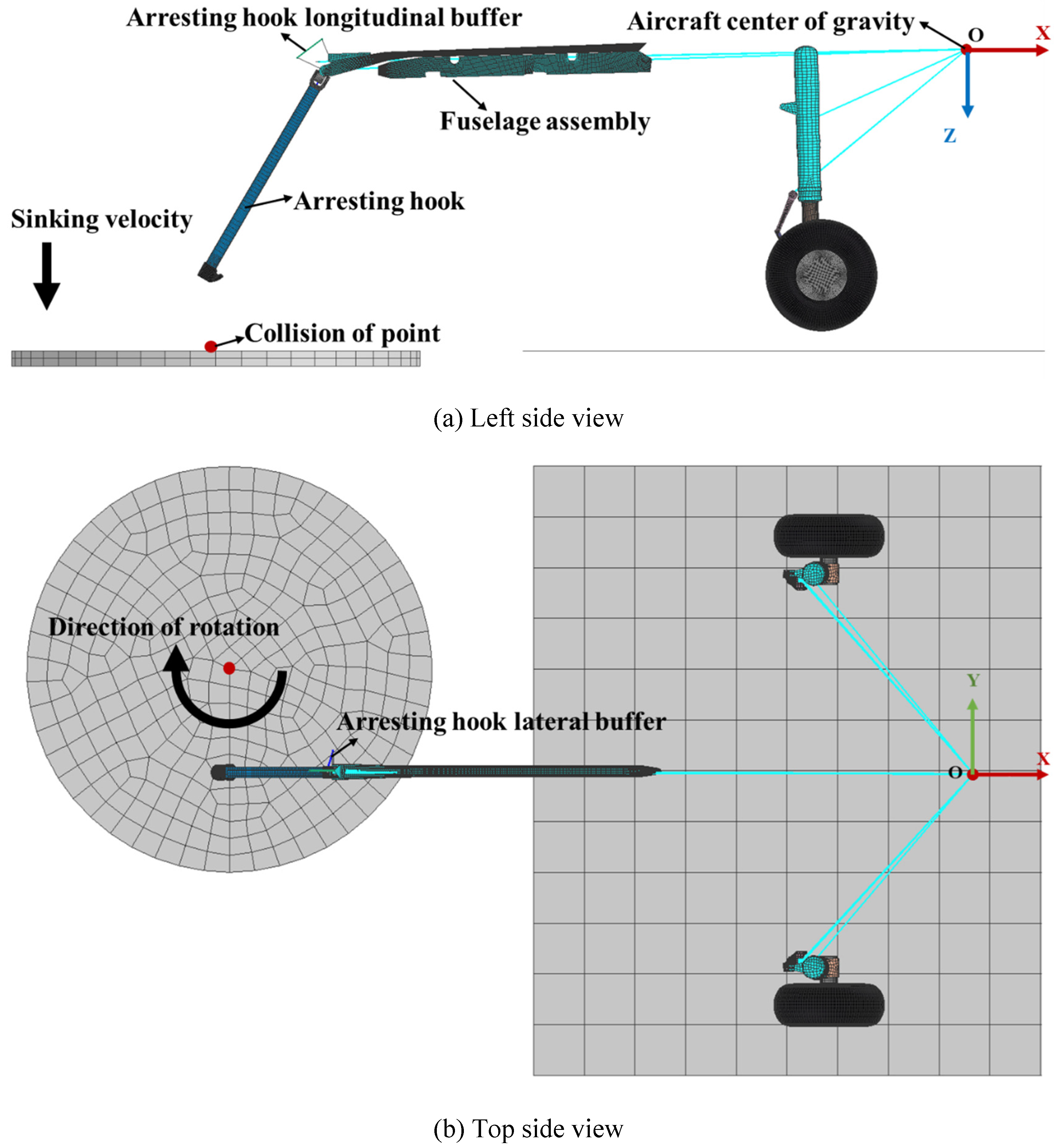
A dynamic simulation is performed to verify the collision rebound of the arresting hook. As shown in
Figure 10(a), fuselage assembly and main landing gear sleeve are defined as a rigid body. Below the arresting hook is a rotating disc, and the collision point between the hook and disc is located at the edge of the disc. The rotation direction of the disc is shown in
Figure 10(b). At the collision point, the relative linear velocity between the hook head and the disc is equal to the velocity of the aircraft. The simulation conditions, including the sinking velocity, horizontal velocity and arresting hook configuration are consistent with the collision rebound test in reference[
14]. By adjusting the nonlinear spring and damping parameters of arresting hook longitudinal buffer, the collision rebound height and distance are matched to the test.
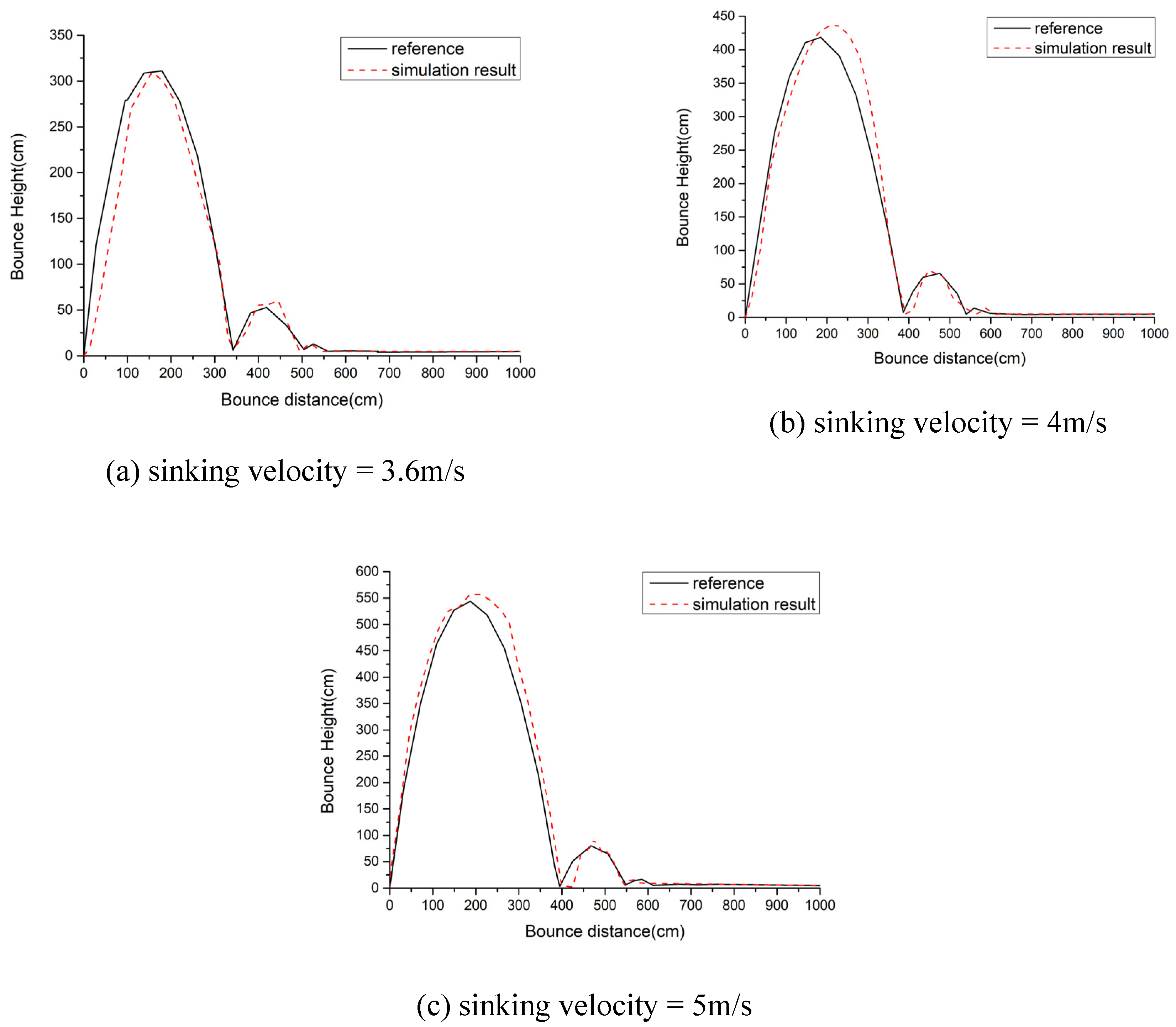
The simulation results for the collision rebound height of the arresting hook, corresponding to sinking velocities of 3.6 m/s, 4 m/s, and 5 m/s, are presented in
Figure 11. With the requirements of increased sinking velocity, the bounce height on aircraft hook increase correspondingly. The satisfactory agreement observed between the simulated and experimental data regarding the rebound height and rebound span of the arresting hook demonstrates the accuracy of the dynamic model established in this paper for the collision rebound process.
4. Numerical simulation and results
4.1. Setting of carrier-based aircraft attitude
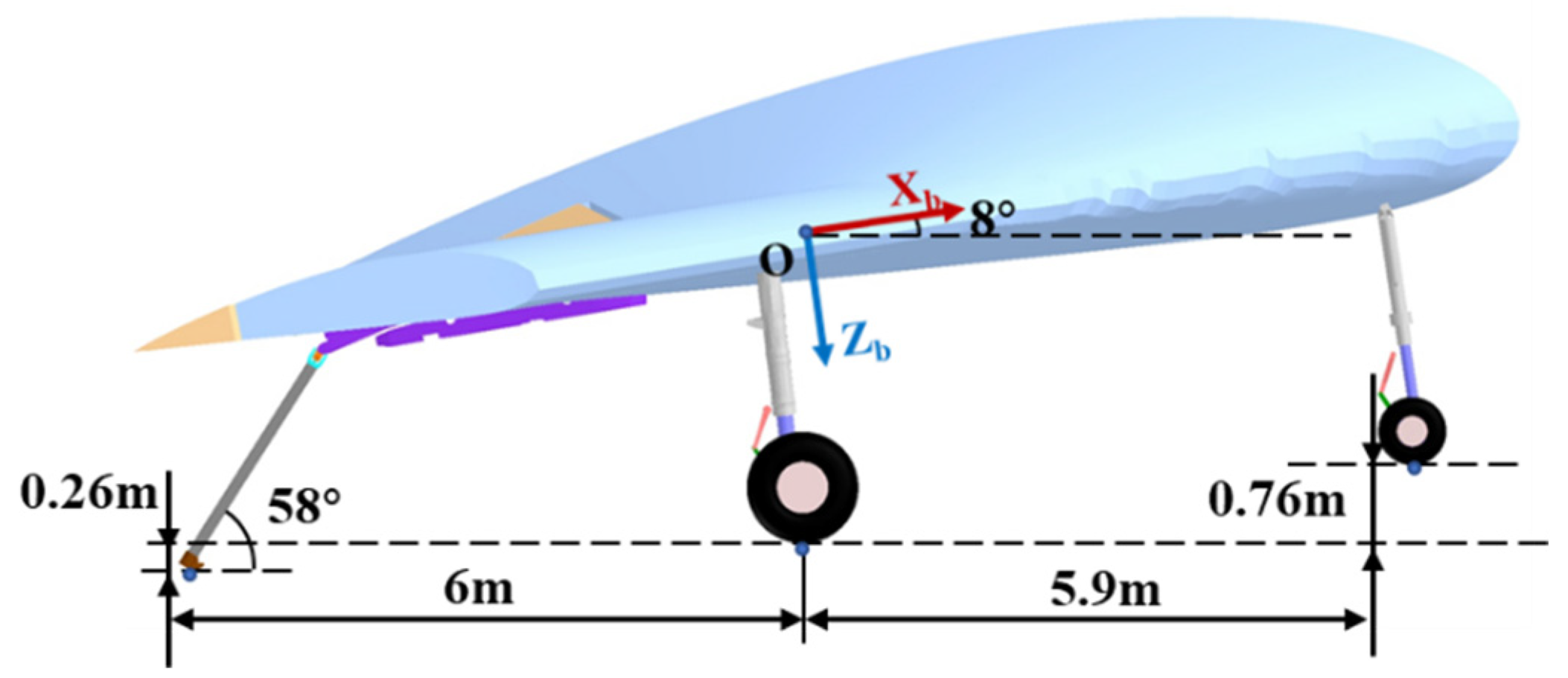
Figure 12 illustrates the initial condition of aircraft. The sinking and horizontal velocity of the carrier-based aircraft at the moment the hook touches deck are same in the following cases. Position of aerodynamic force and thrust is same as described in
Section 2.1.1. The control of variables is conducive to the comparative study of the similarities and differences between different touchdown point and roll angles of aircraft.
4.2. Analysis of hook engaging cable with different touchdown point
The hook engages with the arresting cable after the aircraft hook touches down the carrier deck. And the aircraft starts to slow down under the action of the arresting gear system. In this section, the influence of touch point distance on engagement process is studied. In the numerical simulation calculation, the initial condition of aircraft is represented in
Figure 12, and the distance between touchdown point and cable are respectively set at 0, 2m, 4m 6m, 8m and 10m.
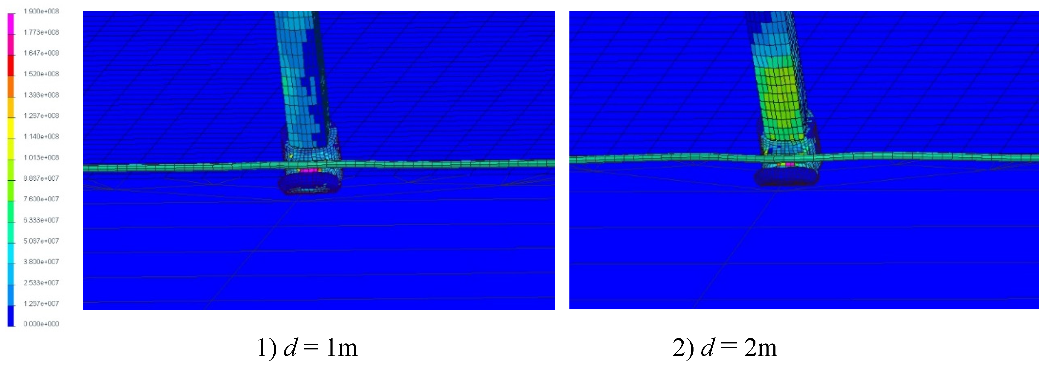
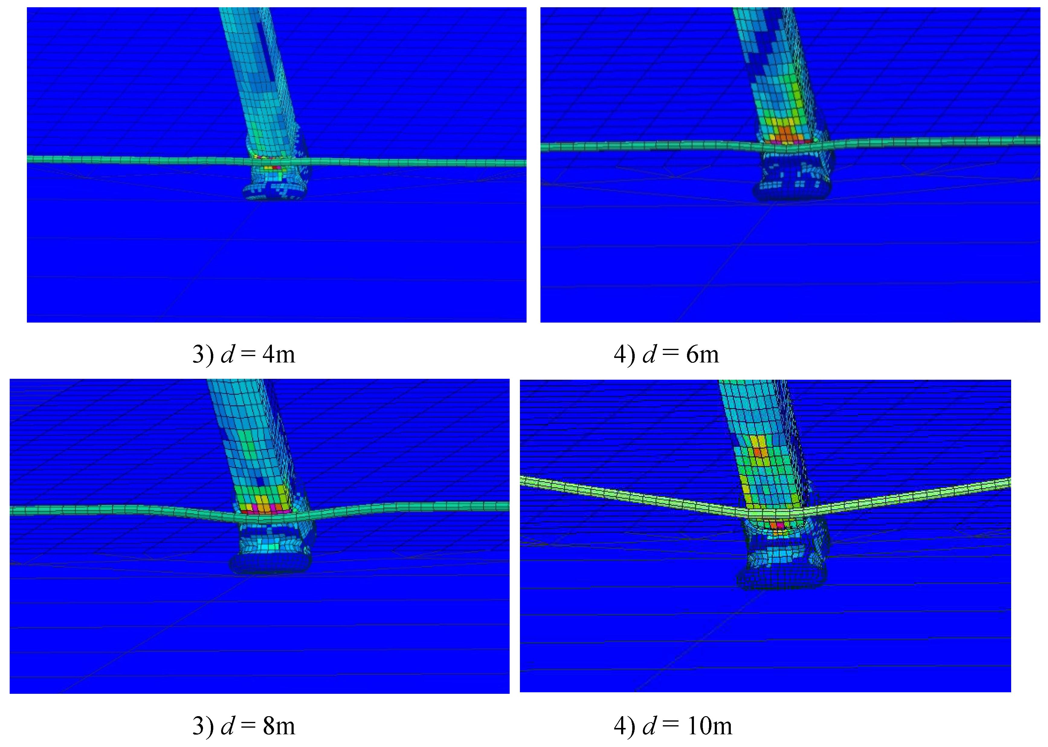
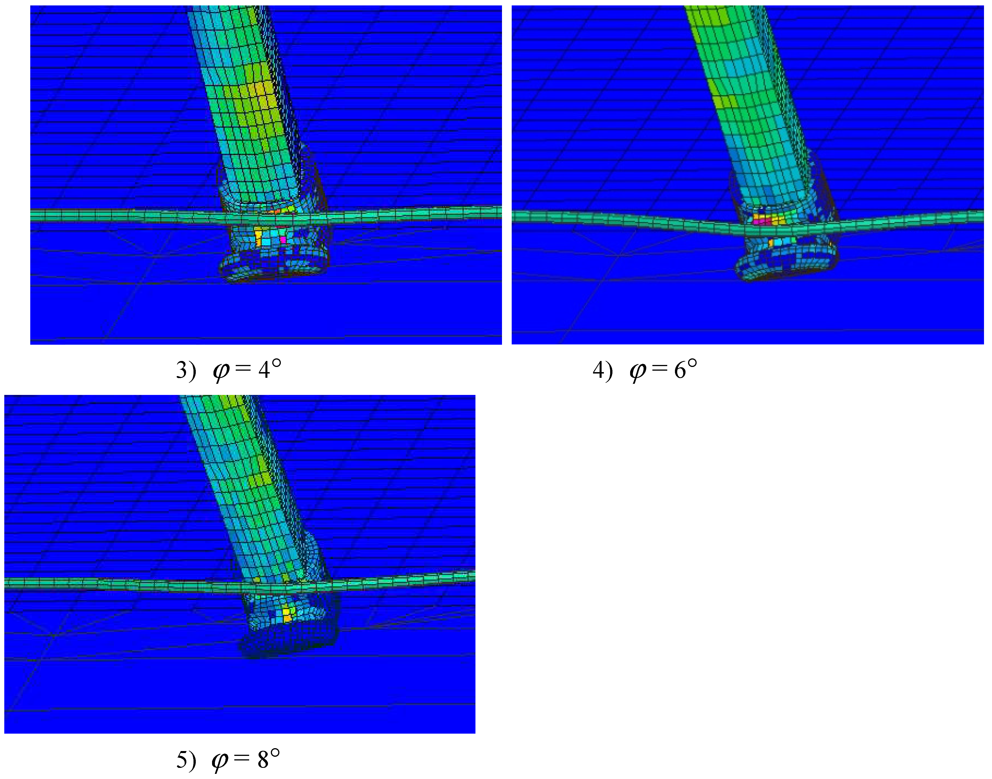
The distance between the touchdown point and the cable determines the rebound height of the arresting hook at the moment of engagement. The engagement location of the arresting cable with the arresting hook varies depending on the touchdown point position. The stress-strain situation of the arresting hook is depicted in
Figure 13.
The contact forces between arresting hook and cable is nearly equal, approximately 54 kN at different touchdown point positions. However, the location of maximum stress on the arresting hook is different. When the touchdown point position is at 1m, the arresting hook rebounds and engages with the cable during the upward phase of the first rebound phase. The maximum stress occurs at the groove of the arresting hook, reaching 187 MPa. When the touchdown point position is at 2m, the arresting hook rebounds and engages with the cable during the downward phase of the first rebound phase. The maximum stress is 179 MPa. When the touchdown point location is at 4m, the arresting hook engages with the cable during the second rebound phase. The engagement location is in the upper part of the hook, resulting in a maximum stress of 172 MPa. When the touchdown point position is at 6m, the arresting hook engages with the cable during the third rebound phase. The engagement location is at the connection between the hook head and the hook shank, leading to a larger high-stress area. And the maximum stress in this case is 184 MPa. When the touchdown point location is at 8m, the arresting hook engages with the cable during the deck drag phase. The engagement location is at the connection between the hook head and the hook shank. And the maximum stress is 188 MPa. When the touchdown point location is at 10m, the arresting hook engages with the cable during the deck drag phase. However, there is an occurrence of the cable being crushed by the wheel, which significantly affects the location of the cable engagement. The location of maximum stress in this case is at the point where the hook shank and the cable engage, with a maximum stress of 165 MPa.
At a descent speed of 4 m/s, the bounce height of the arresting hook remains below the height of the arresting cable. Therefore, under the mentioned conditions, no failures in engaging the cable were observed during aircraft arrestment. The optimal touchdown point for the aircraft on the carrier deck is at a distance of 4 meters from the arresting cable. At this point, the arresting hook undergoes a secondary collision with the deck before engaging the cable, resulting in a low bounce height and a high success rate of engagement.
After the engagement of the arresting hook and the arresting cable, the cable is pulled out under the impact load generated during aircraft arrestment. The tension in the cable is transmitted to the aircraft fuselage through the arresting hook. At the same time, the arresting hook quickly lifts up under the traction force provided by the cable. It takes approximately 0.27 seconds for the arresting hook to reach its maximum position during the lifting process.
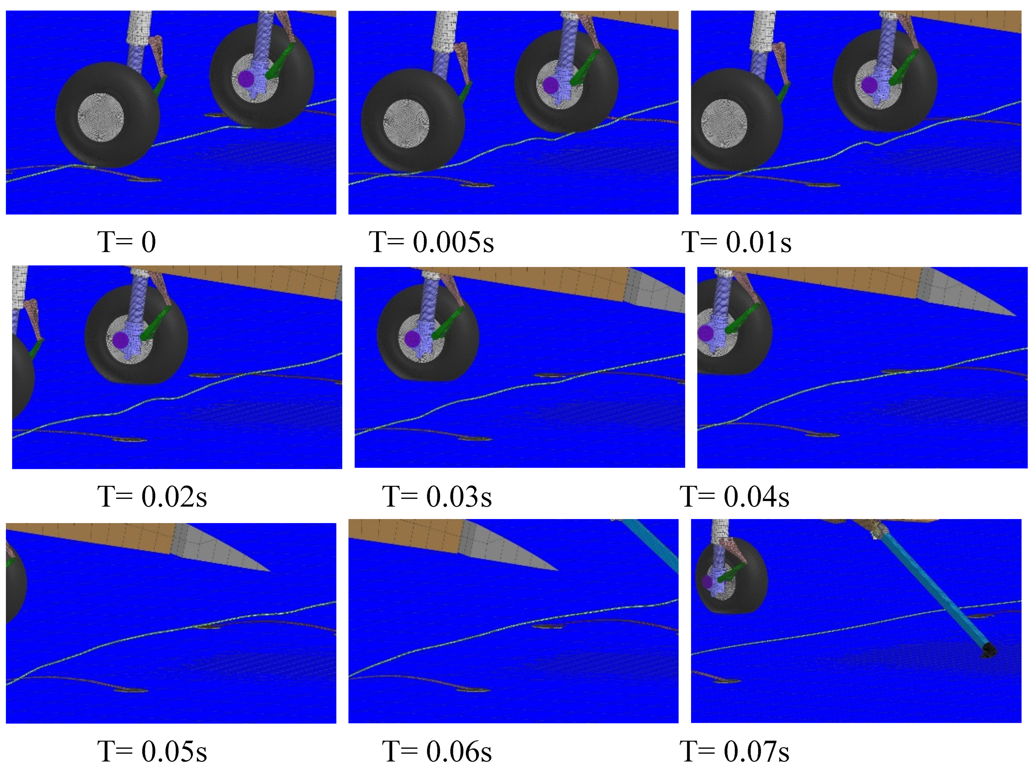
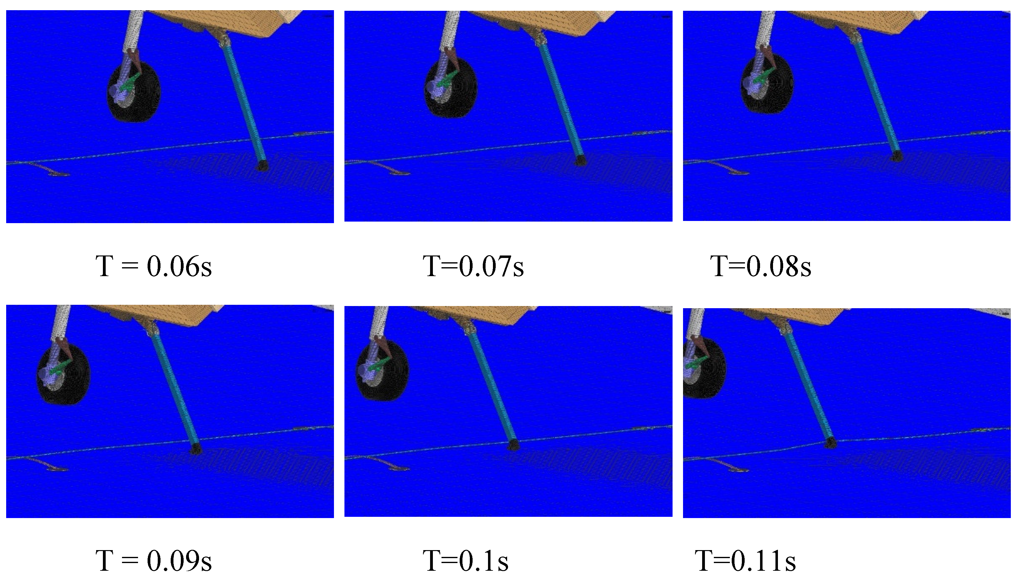
The process of the arresting cable being run over by the tire is depicted in
Figure 14. The cable undergoes bending at the point of tire contact and transmits the bending waves to both sides. The bending wave that is transmitted to the middle of the arresting cable causes the cable to make contact with the deck, resulting in rebound of the cable.
4.3. Influence of aircraft roll angle on the engagement of hook with cable
In this section, the influence of roll angle on the engagement process is studied. In the numerical simulation calculation, the initial condition of aircraft is represented in
Figure 12, and the rolling angle
are respectively set at 0, 2°, 4° and 6°.
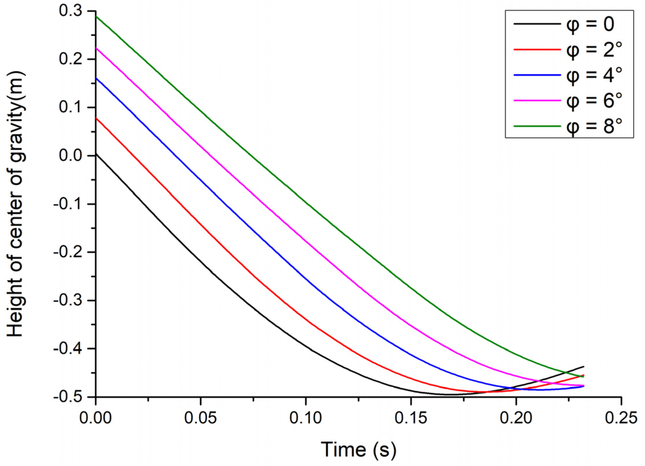
Figure 15 depicts the change in the height of the aircraft's center of gravity after the tire makes contact with the deck. One side of the landing gear touches down earlier, resulting in a higher altitude of the aircraft's center of gravity at the moment of touchdown point compared to the situation without any roll angle. The greater the roll angle, the larger the distance of the center of gravity descent.
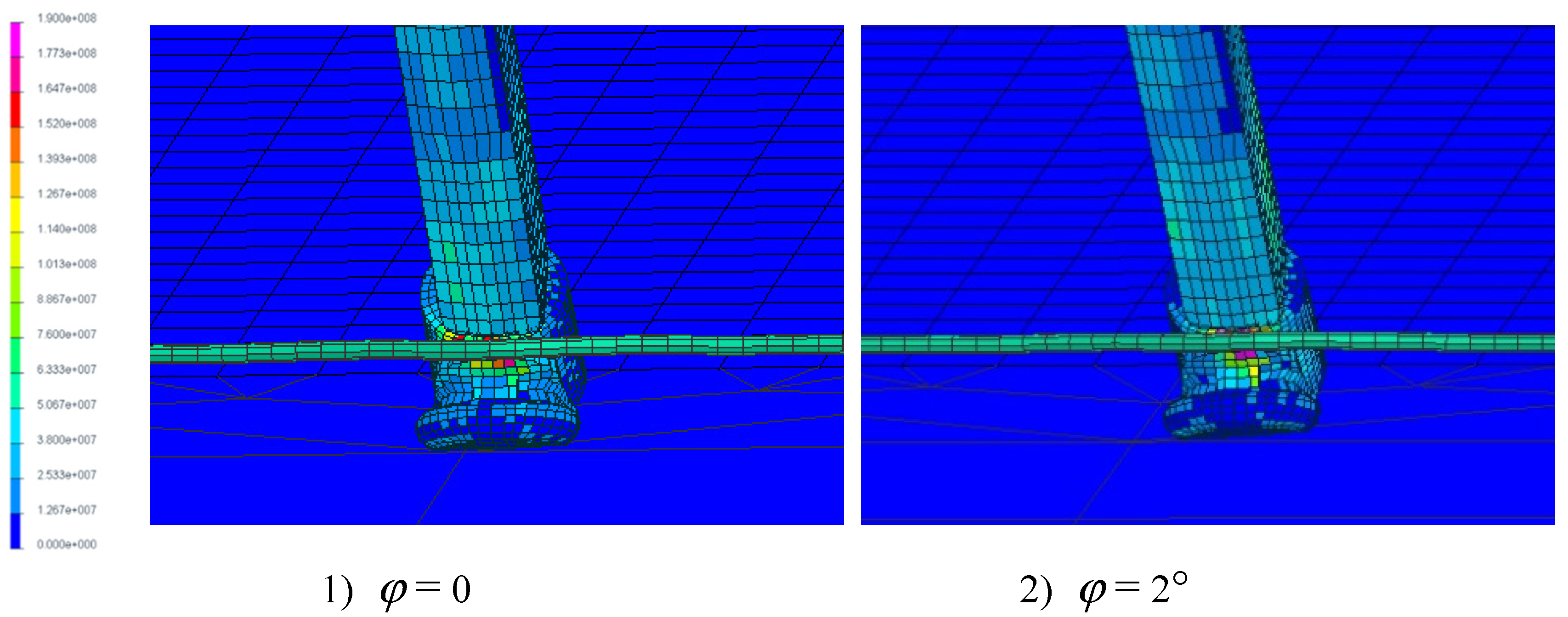
The stress distribution at the moment of hook engaging cable is shown in
Figure 16. It can be observed that the roll angle has a minor influence on the contact force during cable engagement, which remains around 54 kN. However, the roll angle affects the contact area of the hook, resulting in an increased high-stress region in the arresting hook.
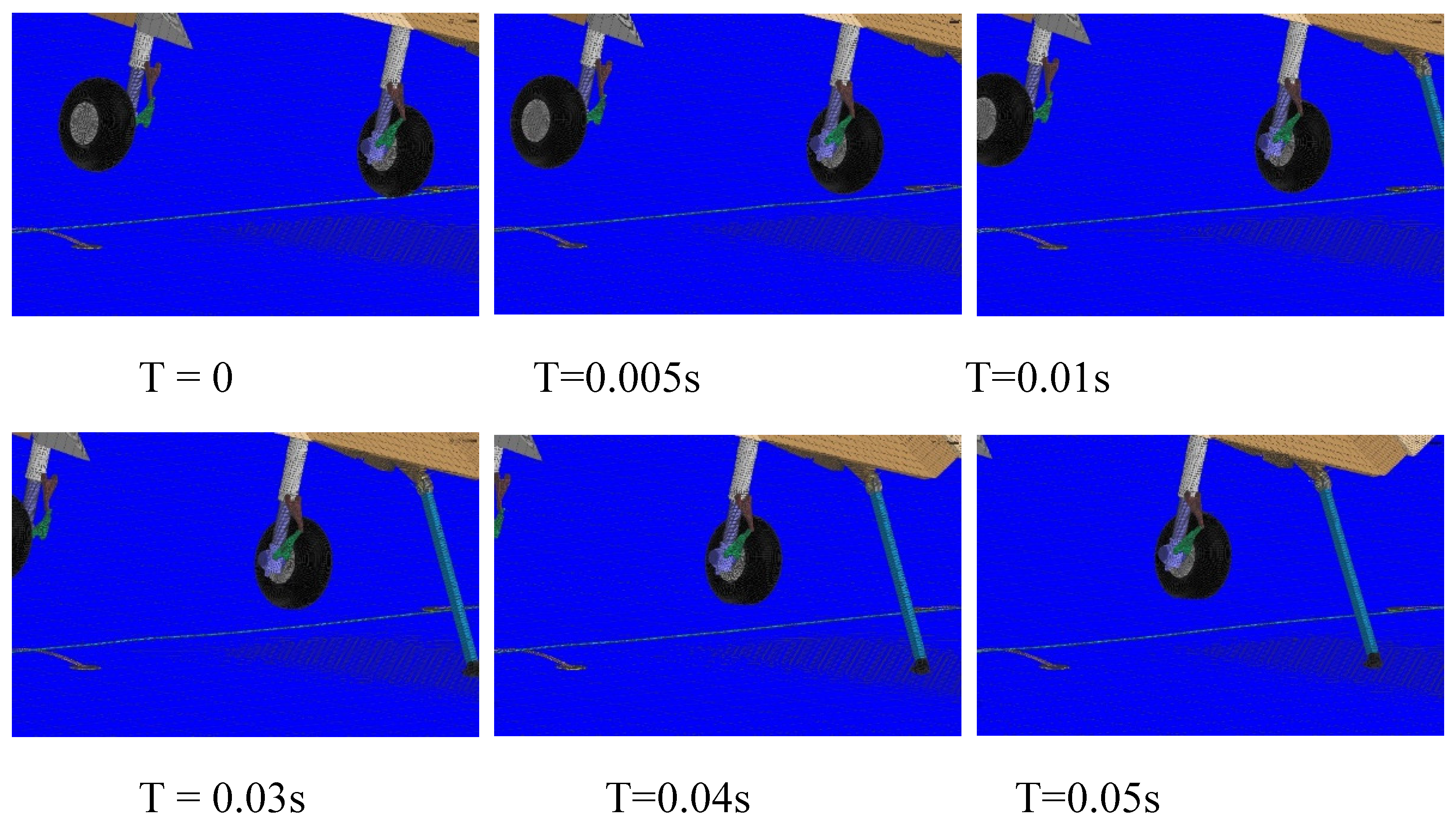
It is worth noting that at a roll angle of 8°, the contact area occurs specifically at the connection between the hook and hook shank, indicating a single-wheel interaction. The process of tire contacting the cable is illustrated in
Figure 17. After one side of the tire makes contact with the arresting cable, the cable bends and transfers the force to the wire roper support on both sides. Subsequently, the cable exhibits vertical movements, oscillating up and down, until the hook successfully engages with the cable.
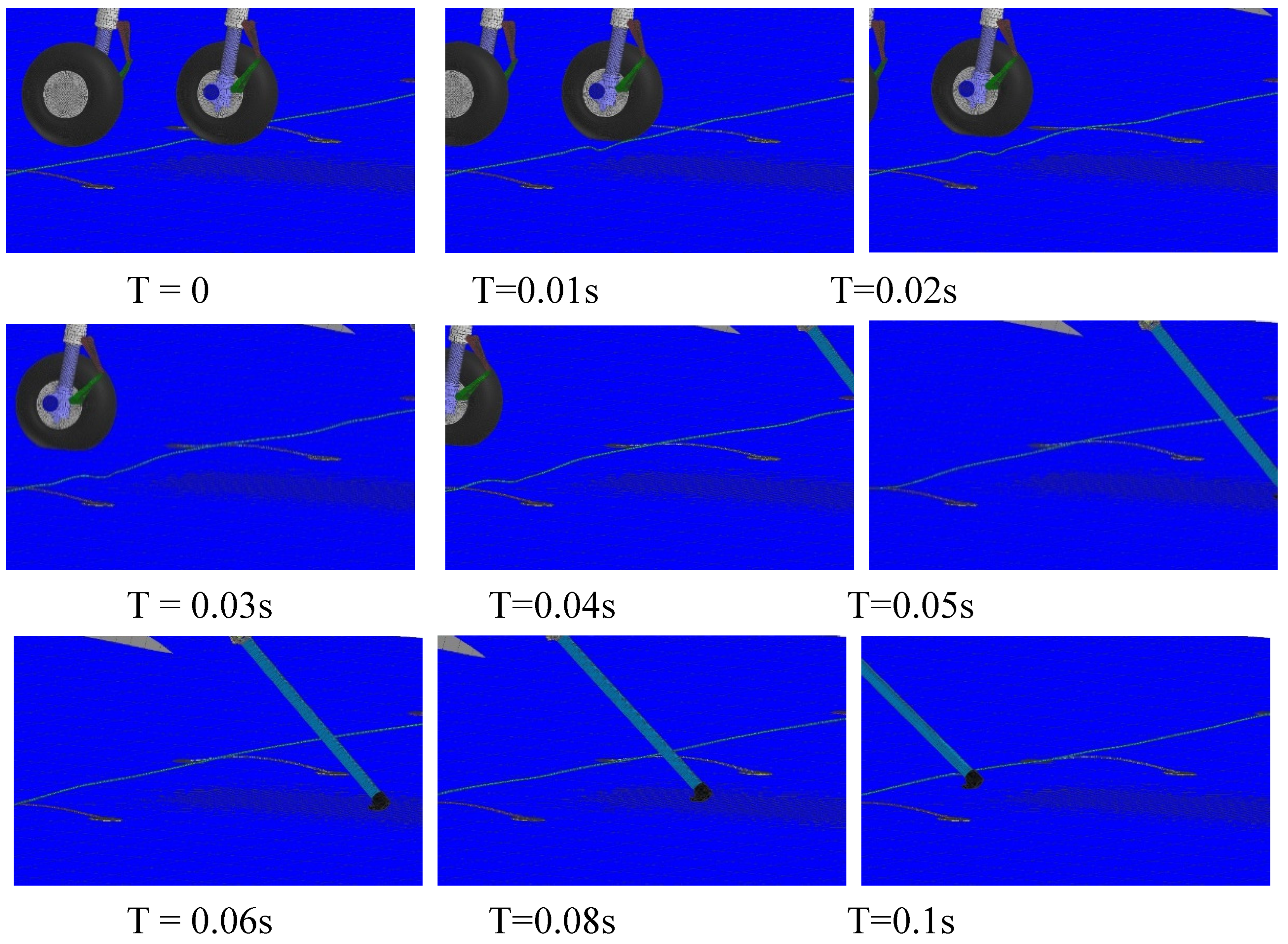
In addition, a scenario of single-side tire roll over the cable occurs when the distance between the touchdown point and the cable is 8 meters and the aircraft experiences a roll angle of 4 degrees.
Figure 18 illustrates the condition 0.1 seconds after the tire touches cable. The interference caused by tire rollover on the motion of the arresting cable is significantly greater than that of tire touches cable. After a single-side tire rolls over the arresting cable, the cable undergoes bending. And the bending is transmitted to the wire roper supports on both sides. Simultaneously, the arresting cable moves towards the direction of the tire motion, significantly affecting the engagement location of the hook and the cable.
5. Conclusions
A successful engagement requires careful coordination and attention to detail from the aircraft, hook and arresting cable configuration and aircraft landing point. In this paper, a FEM-MBD numerical method is used to study the dynamic characteristics of the carrier-based aircraft from the perspective of changing the landing point and aircraft rolling angle. The rationality of the finite element model for solving the hook rebound dynamics was validated by comparing it with the results from experiment. Simulation were conducted to investigate the engagement process under different touch down positions and roll angles. Analyses were performed for the scenarios involving cable grazing and cable roll over.
For a certain carrier-based aircraft, a rigid-flexible coupling model of the hook cable engagement process is established using the FEM-MBD method. The dynamic model is compared and validated against experiment of rebound tests from the reference. The results demonstrate the feasibility of the modeling approach described in this paper.
The contact force at hook engaging cable is nearly the same under different distance between touch point and cable. And the touchdown position affects the height of the arresting hook at the moment of hook and cable engagement, leading to variations in the maximum stress location on arresting hook. When the touchdown point is 10m away from the arresting cable, the cable is rolled over by the tires of aircraft. The arresting cable gets bent at the location where it comes into contact with the tires, and this bending effect is transmitted to both sides of the cable. At the same time, the arresting cable moves rapidly in the direction of tire roll-over. The propagation of bending waves along the cable leads to its contact with the deck and subsequent rebound. In the cases in the paper, due to the high pitch angle maintained by the aircraft, the touchdown point of the hook is far from the arresting cable when the tires roll over it. The hold down damper on the hook contributes to reducing the rebound height of the hook during the engagement with the cable. This low rebound height helps to prevent hooking failure during the engagement process.
Roll angle of aircraft causes one side of the landing gear to touch the deck, resulting in a higher center of gravity at touchdown compared to no roll. As the roll angle increases, the downward displacement of the center of gravity also increases. The roll angle has a minimal effect on the contact force at the moment of cable engagement, but it influences the location of cable contact at the moment of engagement. A larger roll angle increases the high-stress area of the arresting hook during the engagement process.
Under a roll angle of 8° and distance between touch point and cable of 4m, tire touches cable occurs. The cable undergoes bending at the point of contact with the tire and the cable, and the bending leads to small-scale vertical movements of the arresting cable. These vertical movements have an impact on the engagement of the hook and the cable, affecting the hook and cable engagement location. Under the condition of a 4° roll angle and an 8m distance between touchdown point and cable, single-wheel tire rolling over the arresting cable occurs. The interference caused by the tire roll over is greater than that of tire touches pendant. Due to the single-wheel rolling over the arresting cable, the cable rapidly moves towards the direction of tire motion and transmits forces to the wire roper support on both sides. Simultaneously, the forward movement of the arresting cable amplifies the uncertainty associated with cable engagement.
References
- Lawrence, J.T. Milestones and developments in US naval carrier aviation-part Il: AlAA-2005-6120. In Reston: AIAA. In Proceedings of the AIAA Atmospheric Flight Mechanics Conference and Exhibit, San Francisco, CA, USA, 15–18 August 2005.
- NPFC. MIL-A-8863C Airplane strength and rigidity ground loads for navy acquired airplanes [S]. Washington: Naval Air Systems Command, 1993.
- NPFC. MIL-A-8870C Airplane strength and rigidity vibration, flutter, and divergence[S]. Washington: Naval Air Systems Command, 1993.
- NPFC. MIL-A-18717C Arresting hook installations[S].Washington: Naval Air Systems Command, 1993.
- Naval Air Engineering Center. Military Standard: Catapulting and Arresting Gear Forcing Functions for Aircraft Structural Design; MIL-STD-2066 (AS); Navy Air Systems Command: Lakehurst, NJ, USA, 1981.
- Thomlinson J. A study of the aircraft arresting-hook bounce problem, No. 2980[R]. The Principal Director of Scientific Research (Air), Ministry of Supply, 1954.
- Jones L. W. Development of curves for estimating aircraft arresting hook loads: ADA119551[R]. California: Edwards Air Force Base, 1982.
- Zhu Q D, Meng X, Zhang Z. Simulation research on motion law of arresting hook during landing [J]. Applied Mechanics and Materials, 2013,300-301: 997-1002. [CrossRef]
- Mikhaluk D, Voinov I, Borovkov A. Finite element modeling of the arresting gear and simulation of the aircraft deck landing dynamics[C] European LS-DYNA Conference. Petersburg, Russia, 2008. 31-35.
- Deng L, Zhang Y. Nonlinear dynamic analysis of arresting gears using 2D non-material variable-domain corotational elements[J]. Mechanism and Machine Theory. 2021, 163: 104377. [CrossRef]
- Shen W , Zhao Z , Ren G , et al. Modeling and Simulation of Arresting Gear System with Multibody Dynamic Approach[J]. Mathematical Problems in Engineering,2013,(2013-11-10), 2013:1-12. [CrossRef]
- Zhang H , Guo J , Liu J P , et al. An efficient multibody dynamic model of arresting cable systems based on ALE formulation[J]. Mechanism and Machine Theory, 2020, 151. [CrossRef]
- Zhang Z., Peng Y., Wei X. et al. Research on longitudinal dynamics safety boundary of carrier-based aircraft arresting[J]. Aerospace Science and Technology, 2022. [CrossRef]
- Peng Y., Yin Y., Xie P., et al. Reliability analysis of arresting hook engaging arresting cable for carrier-based aircraft influenced by multifactors[J]. Chinese Journal of Aeronautics, 2022. [CrossRef]
- M, ZHANG Z, WEI XH, et al. Dynamics influence analysis of structural parameters on collision rebound of arresting hook[J].Acta Aeronautica et Astronautica Sinica, 2021, 42(7): 224406 (in Chinese).
- Johnny Eggleston. US Navy Aviation Boatswain's Mate E NAVEDTRA 14310: Chapter 3[M]. Naval Education And Training Professional Development and Technology Center, 2001, 33-34.
|
Disclaimer/Publisher’s Note: The statements, opinions and data contained in all publications are solely those of the individual author(s) and contributor(s) and not of MDPI and/or the editor(s). MDPI and/or the editor(s) disclaim responsibility for any injury to people or property resulting from any ideas, methods, instructions or products referred to in the content. |
© 2023 by the authors. Licensee MDPI, Basel, Switzerland. This article is an open access article distributed under the terms and conditions of the Creative Commons Attribution (CC BY) license (http://creativecommons.org/licenses/by/4.0/).
