Submitted:
13 May 2023
Posted:
15 May 2023
You are already at the latest version
Abstract
In the current paper, we present our work towards developing a solution combining computer vision and AI to support footrest design customization in the wheelchair industry. Wheelchairs and postural systems are complex and often user centric in the design process. Those products require a wide range of adjustments to adapt to the various anthropometries and disabilities of patients. Most commercial products, dedicated to severe disability, also include a series of additional elements, designed to keep the patient in a comfortable but “fixed” position. Such systems do not allow to “fix and maintain” the position of patient foot, especially for patients who have no control over their lower limbs. For that reason, it becomes essential to supply wheelchairs with specific elements to hold patient's shoe in place. Commercial foot supports are typically developed on standard sizes and do not always cover the entire population. In addition, those designs are based on standard shoes, thus they do not lend themselves well to adapting to special shoes or orthopedic shoes. Feet final position therefore becomes a key element in correct postural management. In this paper, we investigate the use of computer vision and AI to correctly define customization parameters of the footrest. The proposed design has been developed based on the specifications received from the Pro Medicare S.r.l orthopedic technicians. We present suitable algorithms, design principles and well defined components towards the implementation of our proof of concept. We also present the testing activities we have undertaken and the obtained performance results.
Keywords:
Additive manufacturing
; Artificial intelligence
; Design customisation
; Wheelchair
; Footrest
; Kyklos 4.6
; Circular economy
1. Introduction
Additive manufacturing (AM), also known as 3D printing or rapid prototyping, is one of the most appealing aspects in industry 4.0 since it promises a radical transformation to industrial production by enabling the creation of lighter, stronger parts and systems 1. AM is expected to gain more and more momentum in the future thanks to the advantages that it offers over traditional manufacturing. Cost reduction, time efficiency, and customization of products with complex geometries seem to be the main aspects driving the rapid deployment of AM in production environments 2. Unfortunately, variability in products quality and process reliability remain a big challenge that needs to be addressed 2. The use of AI in the context of additive manufacturing is still being explored by academia and industry. The related use cases cover the entire production life cycle and range from design recommendation, through defect detection, to predictive maintenance.
Designing and producing wheelchairs is a big challenge since it is expected that this wheelchair will offer appropriate seating and postural support without compromising important aspects such as strength and safety2. Wheelchairs are composed of a series of elements designed to be adjusted and adapted to the various anthropometries and disabilities of patients. Most commercial products, dedicated to severe disability, also include a series of additional elements, designed to keep the patient in a comfortable but “fixed” position. Postural pads and belts are typical elements used on cushion backrest. Feet final position therefore becomes a key element in correct postural management. Most wheelchairs have fixed or foldable planar footrests as showed in the following picture.
Figure 1.
(left) Standard footrest design, (right) Footrest design example. Alt Text: This figure shows a standard footrest as well as a new one that will be designed by Kyklos 4.0.
Figure 1.
(left) Standard footrest design, (right) Footrest design example. Alt Text: This figure shows a standard footrest as well as a new one that will be designed by Kyklos 4.0.
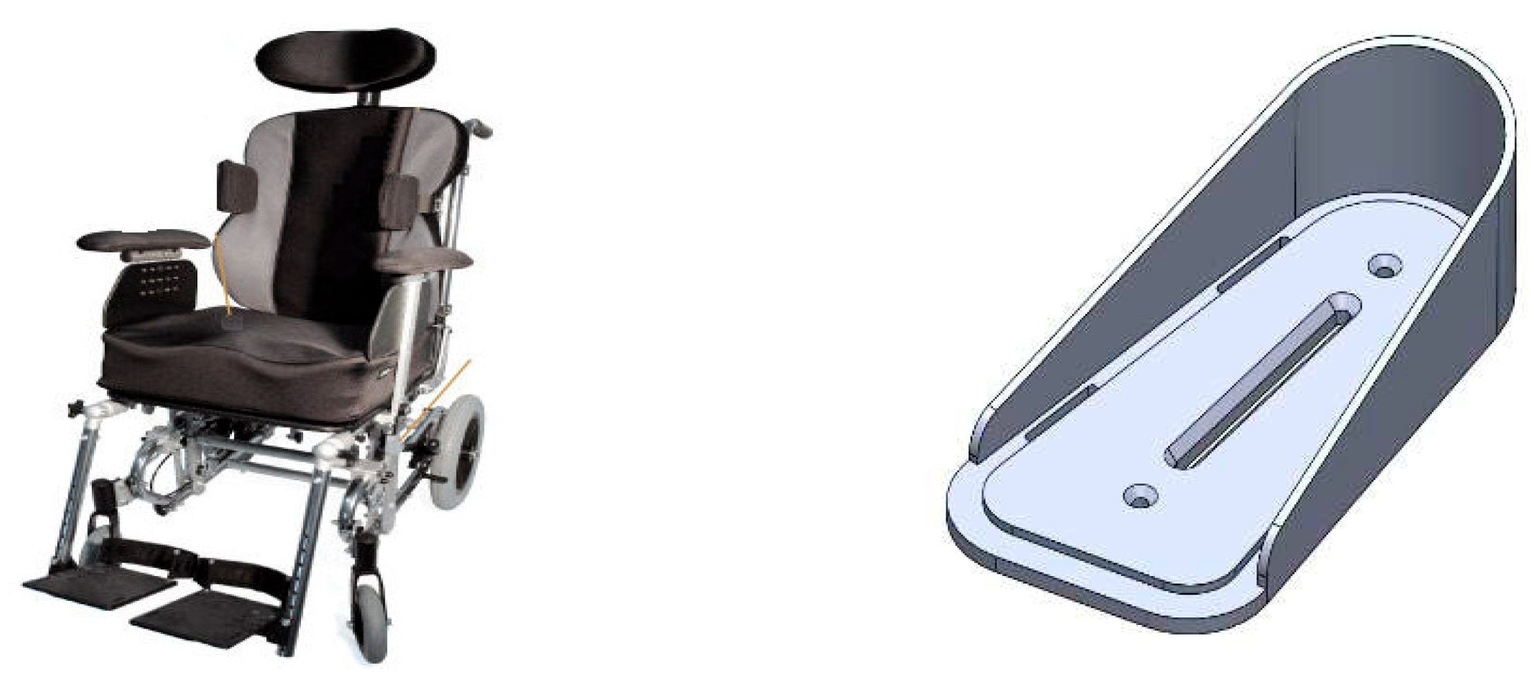
Such systems do not allow to “fix and maintain” the position of patient foot, especially for patients who have no control over their lower limbs. For that reason, it becomes essential to supply wheelchairs with specific elements to hold patient’s shoe in place. Commercial foot supports are typically developed on standard sizes and do not always cover the entire population. In addition, those designs are based on standard shoes, thus they do not lend themselves well to adapting to special shoes or orthopedic shoes.
Based on these considerations, we decided to exploit Artificial Intelligence to correctly define customization parameters of the footrest. The proposed design has been developed on the basis of the specifications received by orthopedic technicians from the company Pro Medicare S.r.l3. The system consists of a base that can be fixed by screws to standard footrests already provided in the wheelchair, and its design provides two vertical walls, conformed to the shape of the shoe, which stabilize and firmly maintain the heel and sides of the shoe.
Once the customization parameters are computed, this information will be communicated to a 3D modelling engine that will adapt the CAD model and consequently to the 3D printer to produce the footrest. The main goal of this new approach is to simplify the procedure to obtain best fitting design,
2. Related Work
Although the use of AI in the context of additive manufacturing is still in an exploratory phase, the use cases that have been demonstrated so far by academia and industry seem to be promising. The manufacturing stages where the AI applications were proposed cover the entire AM life cycle.
The AI research company EMERJ 3 has explored the potential use of AI in additive manufacturing and found that the related applications span the following four segments 4,
- Improving efficiency in the prefabrication stage: Here, a user willing to manufacture a given part, takes the CAD files describing this part as well as the desired output and check whether AM is suitable for processing the production. In the context of generative design, machine learning can be in particular used for generating and evaluating digital models that will be used in the 3D printing production
- Defect detection: An AM technology, like any other, is prone to defects. This means the part that was produced from 3D printing could reveal some aberrations. In order to detect such failures and discard the concerned parts, computer vision and AI can be utilized. Here, the printing process will be inspected through high-resolution cameras, and suitable machine leaning algorithms will be used to match the recorded patterns to well-known defects in the AM technology
- Real-time build control: The idea here is to take defect detection using computer vision and dynamically control 3D printers to compensate for the defects. This approach will certainly help in limiting waste of time and materials
- Predictive maintenance: According to Fortune Business Insights 5, the 3D printing industry market size that was US$ 10,41 billion in 2019, could reach US$ 54,96 billion by 2027. An important segment in this market is the spare parts industry 6. Concretely, 3D printing is offering many benefits to this industry including less production costs, 3D digital inventory (printing parts on demand), and faster delivery time. Machine learning and predictive maintenance will also play a crucial role in the expansion of this segment. For instance, applying machine learning to predict in an accurate way the remaining useful life of a certain part can help in scheduling an appointment for the part replacement.
The authors of 7 reviewed machine learning (ML) methods used in AM and divided the different approaches into three categories: geometrical design, process parameter configuration and anomaly detection. In the area of geometric design, AM enables the construction of complex lattice structures with different material distributions that meet the requirements of the respective application. In the part process parameter configuration, the authors address the work that uses ML methods to influence the quality of the final printed products through the choice of process parameters. In addition, justifications for the use of ML are provided, as well as recent literature such as 8 and 9 on the application of ML to optimize and interpret the analytical relationship between process parameters and product quality. Finally, the authors address the approaches (computer vision methods, improved test setups and novel simulation approaches) that deal with the detection of anomalies in the manufacturing process (detection of defective ones). These methods aim to assess the printing condition and product quality efficiently and accurately.
The use of machine learning in AM was also discussed in detail in 10. The authors analysed fifty papers, identified where and how machine learning techniques were applied to AM, and organized in an easy way the obtained findings. The approach followed by the authors partially overlaps with the one discussed previously by EMERJ. Here, the use of machine learning was explored through all the production lifecycle stages, namely, design, process planning, building, post processing, and testing and validation (10, 11). Within each stage, a variety of functions can be implemented using machine learning techniques as it is shown in Table 1, the implemented techniques are used for instance for prediction, performance optimization, defect detection, classification, regression, or forecasting (10, 12).
In this paper, the use of machine learning for AM falls within the “design” stage and under the “design recommendation” function (see Table 1). However, the context is completely different. In 13, machine learning was used to assist inexperienced AM designers by offering them an automated AM design feature recommendation method. The latter combines hierarchical clustering (unsupervised learning) and support vector machine (SVM) (supervised learning). Other researchers (14, 15) have used various neural networks techniques to help designers estimate build time factors for instance. In KYKLOS 4.0, a machine learning based solution was developed to predict some anthropometric measurements needed for the design of the footrest of the wheelchair. The solution is customer/user friendly since it only requires a picture of the contour of the shoe of this person. Here, computer vision and Neural Networks (NN) are combined to predict the length, top width, and the bottom width of the footrest. The generated information is sent then to the 3D modelling component to further design this part.
3. Wheelchair design support: The Kyklos 4.0 Approach
To be able to accomplish the proposed workflow to produce personalized products using Additive Manufacturing, the collaboration of various components is required. The functionality introduced by the DL Toolkit, a Data Analytics Enabler component in its essence, is leveraged to support the functionality of the KYKLOS 4.0 Smart Design Enablers.
In fact, a specific part of Kyklos 4.0 Project is focused on mass customization through the development of a product parametric design methodology able to collect input data from anthropometric measures, design constraints and producer expertise, and to automatically process and translate them for using as design inputs for dimensioning a 3D parametric model of the customized product. The entire workflow includes the best definition of variables (dimensions) that should be used as inputs for the final product configuration; the usage of a 3D parametric model in order to create a custom part, and the introduction of specific tool to simplify procedure and measure of custom parameter. Specific components developed within this project, as listed below, are closely connected to the DL Toolkit an allows the definition of customizable products such as the footrest design:
- Parametric Design Methodology by CETMA: This component was specifically developed in order to transform anthropometric dimensions into custom parameters for the wheel chair production. This methodology also defines which are the main important dimensions that should be extracted by the DL Toolkit through the image contour analysis. The output of this approach will be a solution that could be applied to create product parametric design engine. The analyzed workflow includes the best definition of variables (dimensions) that should be used as inputs for the final product configuration; the usage of a 3D parametric model in order to create a custom part, or a custom assembly, based on provided inputs. Thanks to this methodology, and guided by Pro Medicare technicians, we were able to define a set of variable to determine the footrest correct parametrization. This approach could be used for mass customization thanks to the use of both the DL Toolkit as well as the Web 3D Modelling Component.
- Web 3D Modelling Component by TWI: The Web 3D Modelling component receives the extracted dimensions as input. Using the functionalities provided by the Web 3D Modelling component, a watertight CAD model of the footrest is automatically generated. This tool is based on scripting modelling that is able to drive the design of a 3D model, using a set of independent variables. In this case, these variables are the extracted dimensions presented in this paper. The footrest design is built in a way to be able to be automatically exported in a watertight 3D printable format, and pushed for manufacturing via AM by just receiving input from the DL toolkit. This can be done rapidly to provide different configurations of the footrest template and conform to a variety of patient characteristics (i.e. different shoe size, shape, etc.). An example of generated footrests can be seen in Figure 2.
The footrest models presented in the above figure are exported in both .stl and .step format to be either directly 3D printable or editable in other CAD software. A key factor to enable the generation of highly personalized models is the utilization of web collaboration tools. The Web 3D Modelling Component has been developed in a way that it can be accessible through the web. The patients are able to access the tool, upload a picture of their shoe contour traced in a piece of A4 paper and then further process the generated 3D model. The overall workflow for the AI driven design of the footrest is presented in Figure 3.
By using the design principles dictated by the Parametric Design Methodology, we developed a framework for providing personalized products such as the footrest component. In the heart of this framework lies the scripting modelling language CADQuery. The footrest component has been designed following an algorithmic approach that enables the generation of the footrest component as an output of a constraint driven function. The CADQuery script receives as input the independent variables of the design and generates the corresponding personalized design according to the input received.
The constraints set by the anthropometry of each specific patient regarding his/her shoe can be summarized by the following two parameters, (i) Shoe Length, and (ii) Shoe Width. Therefore, our design would need to accurately cover each combination of the aforementioned parameters. To be able to implement the above constraints in our design, the following parameters to use as independent design variables are received as input from the Parametric Design Methodology, the (i) Heel Radius – r, the (ii) Shoe Length – L, and the (iii) Footrest Angle – φ. The anthropometry of the patient, as well as the design variables, are presented in Figure 5.
The user input (i.e. shoe contour), inspection of the generated model, further processing, and export for 3D printing are all implemented inside the Web 3D Modelling Component of the KYKLOS4.0 project. The interconnections between the front-end interface, DL Toolkit, and CADQuery script enable the generation of virtually infinite number of personalized products through a user-friendly interface. An example of generated footrest, as well as further processing controls is presented in Figure 6.
4. Footrest Design Support
4.1. Overview
The footrest design is supported by using a streamlined dimension extraction of the footrest. This is done by using a computer vision component to extract the dimensions of the contours of the shoe on an A4 sheet of paper, followed by using a machine learning component trained to rectify the computer vision biases as opposed to the dimensions measured by hand.
- Contours of a patients’ shoe are drawn on an A4 sheet on paper and photographed.
-
The model extracts the dimensions of an object using OpenCV (OpenCV is a computer vision library with which we can extract the dimensions of an Object from an image if a reference object with known dimensions exists in the image)
- Computer vision-based extraction of shoe length from an image
- Computer vision-based extraction of top shoe width from an image
- Computer vision-based extraction of bottom shoe width from an image
- It uses the dimensions found by OpenCV and feeds them into a ML-model, which predicts the anthropometric measurements of the patient’s shoe.
The following figure (Figure 7) gives an overview of the overall structure of the implementation.
4.2. Computer Vision Component for the Footrest Design Support
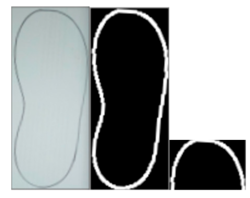
The second step described in Figure 7 requires a step wherein an A4 sheet is detected within an image and cropped out. The current implementation draws the contours of the image and then extracts the largest A4 sheet shaped object in the image as shown in Figure 8. The A4 sheet extraction takes place to be able to have a reference when attempting to evaluate the shoe contour dimensions.
The Computer vision component also has three extraction respective methods with which the three individual shoe contour dimensions are evaluated:
- Length extractor: the length extractor is a function that fits a linear line to the contour, finds its intersections with the shoe contour and evaluates the pixel distance between the top and the bottom pixels. This value is then divided by the density of the image (Pixels Per Millimetre Square), which can be calculated when one considers the dimensions of the A4 sheet.
- The top width extraction crops the contours of the show using a minimum area rectangle. It then crops the top 30% of the resulting contour and then evaluated its width. This method has proven to be highly effective in that the estimations and the true labels correlated heavily.
Figure 10.
Top width extraction. Alt text: This figure shows how the top width is computed.
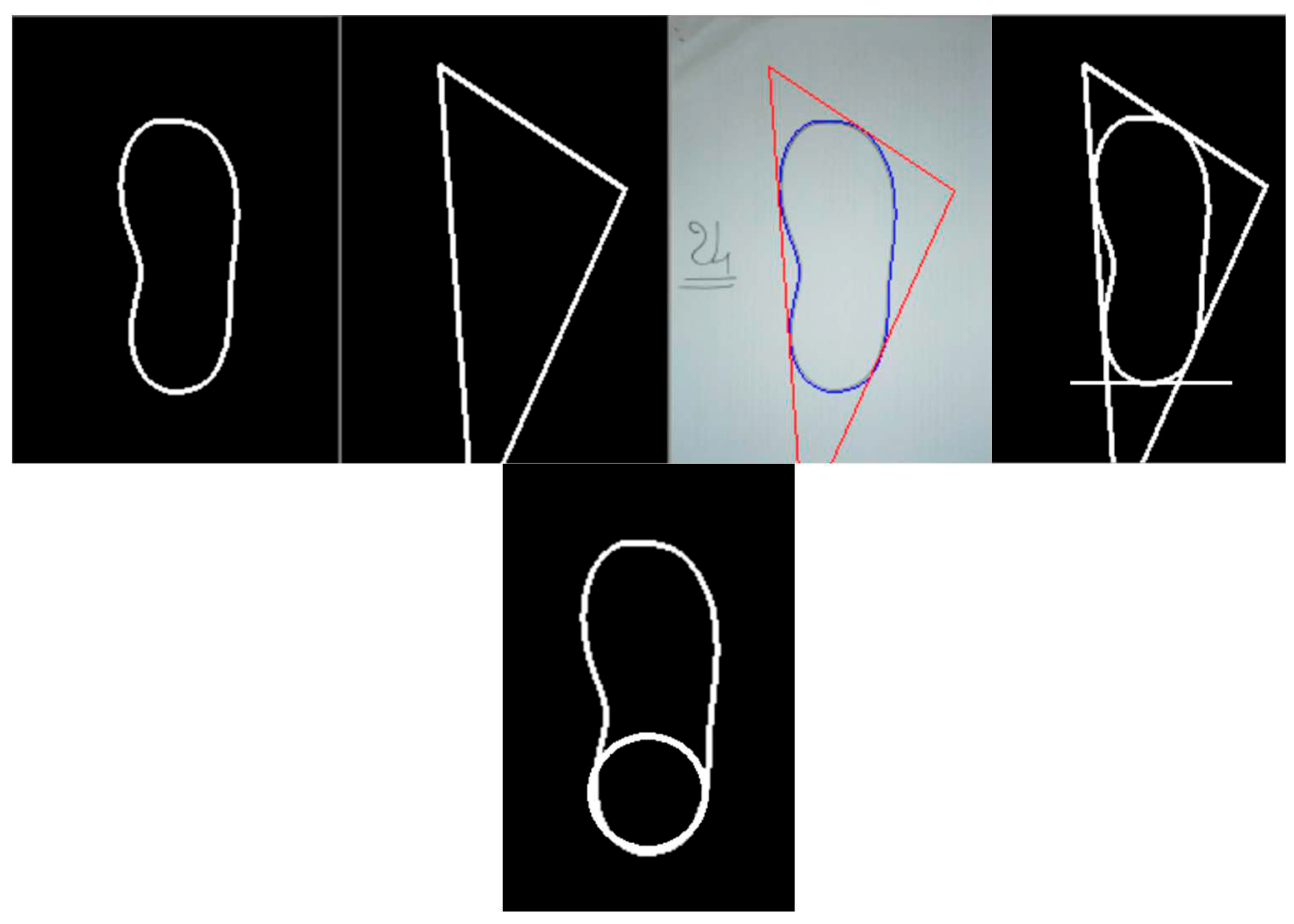
- Bottom width extractor is the more complicated algorithm of the three; it draws a minimum area triangle around the shoe, which due to the shape of the shoe will always have a vertex underneath the shoe and two towards the upper parts. Due to the orientation of the triangle two of its edges will intersect with the circle forming the back part of the shoe. We draw a straight line from the lowest most point in the contour as a line that passed through there must necessarily form a constant function. Every three lines can form a circle, so we use the information we have about the three lines and evaluate the value of the diameter of the circle formed between them above the constant line. This diameter appears to correlate with the measured bottom width labels. The following graph depicts the process under consideration.
Figure 11.
Bottom width extraction. Alt Text: This figure shows how the bottom width is extracted.
4.3. Deep Learning for the Footrest Design Support
The extracted values of the computer vision algorithm can have some constant imbedded biases. The algorithm could always overestimate or underestimate certain values.
To deal with this the value estimations of the computer vision algorithm are feed into a machine learning algorithm which rectifies any error or bias shown by the computer vision component. The machine learning algorithm constitutes a simple Multilayer perceptron with 1 hidden layer of size 2 nodes. We elected to use a smaller model due to training data size constraints. Every dimension has its own trained model, meaning that 3 models are trained for the length, the top width, and the bottom width respectively.
Note that we used Adam optimizer 16 and we found that a learning rate of 0.01 works well with our limited data.
5. Experiments
5.1. Data Overview
The data that has been used in this work is labelled training data composed of the A4 sheet scan or image in accordance with the image taking guide -said guide can be found in the appendix.
The data includes the hand-made measurements of the shoe, which are only used during training, as the actual use case involves streamlining the dimension measurement by outsourcing it to the algorithm. Shoe samples collected so far have the following features.

Table 2.
Shoes samples.
| (No. samples = 24) | length | Top width | Bottom width |
|---|---|---|---|
| Max | 275 mm | 110 mm | 85 mm |
| Min | 135 mm | 65 mm | 48 mm |
| Average | 216 mm | 86 mm | 64 mm |
| Median | 222 mm | 88 mm | 65 mm |
5.2. Data Structure
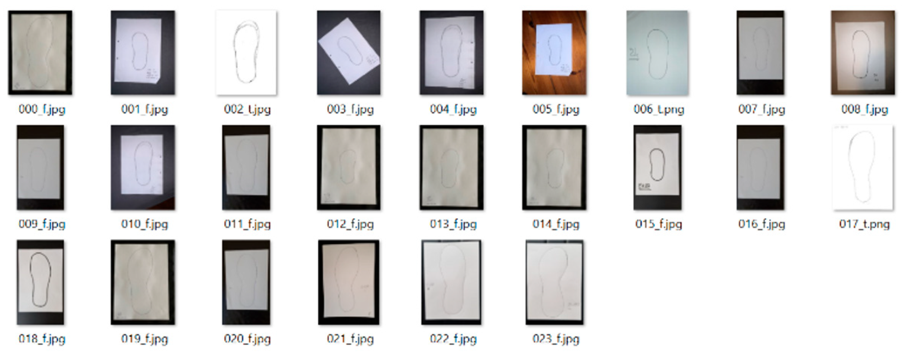
The raw data is composed of an images folder that contains all the images stored whose title is best described using the following regular expression:
[0-9]{3}_[ft].jpg
Example figure that shows an example raw images directory. The letters f and t at the end of the name refer to true and false as an answer to the question of whether the image constitutes a scan or a photographed image of an A4 sheet of paper.
Figure 12.
Samples of shoes’ contours. Alt Text: Some samples of shoes’ contours used in the experiments.
Figure 12.
Samples of shoes’ contours. Alt Text: Some samples of shoes’ contours used in the experiments.
The labels are stored in a numpy file which contains a single numpy array with the shape nX3, where n is the number of traces.
5.3. Data Collection Procedure
This paragraph simply gives an overview of how the data (mainly pictures) is being collected in the promedicare use case.
5.3.1. Basic Idea
Taking shoe image
- Place the shoe in the center of the A4 sheet
- trace the outline of the shoe around the sheet with a pen/marker
- Take an image of the outline or scan it
Measure actual shoe dimensions
Motivations: Only relying on the picture can make our software overestimate the actual shoe sizes. So it’s very helpful to measure the actual shoe dimensions by hand.
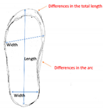
- Needed measurements: The top width, the bottom width and the length as shown in the picture.
5.3.2. Thing to take into account when taking the picture
1. Blank non-white Background: If you don’t send a scan, please make sure that the background has no visible patterns. Also make sure that there is a visible contrast between the background and the the sheet of paper (Please don’t place sheet on a white background)
2. No Folds: Please make sure that the A4 sheet is not folded and is completely visible
3. No shadows: Images without shadows and ones that are evenly lit are sure to work in the program
4. Pens/Marker: Use a pen or marker when marking the outline and not a pencil
5. Naming: We would greatly appreciate it if you titled the image as in the example in millimeters
For example: shoe_180_77_65.png, where the length=180mm, top width=77mm, and bottom width=65mm
Examples:
Here are good and bad example of images we’ve received or taken so far,
Table 3.
Examples of good and bad taken images.
| Example | Taken Image | Description |
|---|---|---|
| 1 | 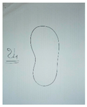 |
Scan image is perfect. The Shoe is placed up straight in the center of the image. It was taken with a scanning device, the lines are clean and visible. Name: img_174_75_60_t.png |
| 2 | 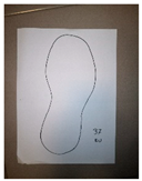 |
Image is very good. The background shows a good contrast, the entire A4 sheet is visible and the shoe is properly marked. The shoe isn’t perfectly lit, but that’s okay. Name: example_276_115_88_f.jpg |
| 3 | 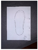 |
Image is very good. The background shows a good contrast and the entire A4 sheet is visible. The lines were drawn with a pen. Name: example_276_115_88_f.jpg |
| 4 | 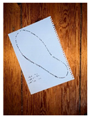 |
The image is not good. We took this image with a noisy background. It interferes with the current implementation of the software. The image does have good lighting, which is good. |
| 5 | 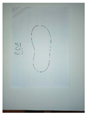 |
The image is not good. The drawing is great, but there is no contrast between A4 sheet and the white background. |
5.4. Performance
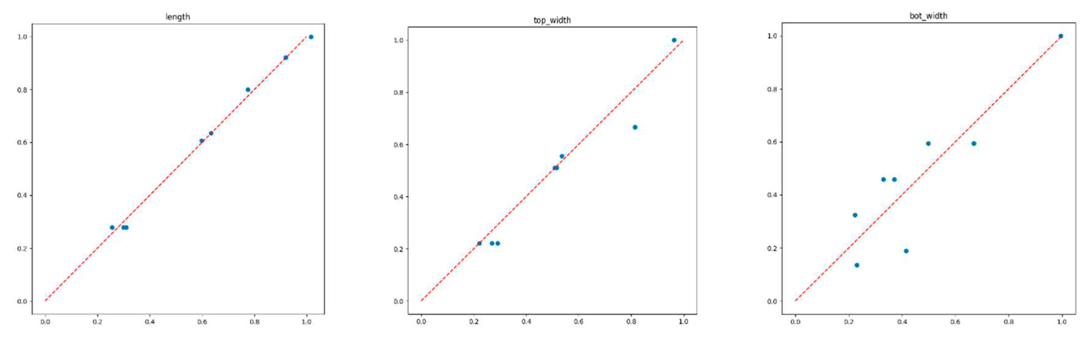
Here are graphs showing the performance of the computer vision component. Due to the small size of samples (N=24) that were collected, the machine learning component showed negligible advantage over the pre-processed data. The values were scaled using a Min Max Scaler 17, a transform that scales each feature to the range between 0 and 1, where the minimal number is mapped to 0 and maximum value to one.
The length shows a very tight correlation, which indicates
that our length estimation heuristic was very accurate when used with our
training data. The same can be said to a lesser extent regarding the top width
estimations and even less so about the bottom width estimations. We did however
see a high correlation between the bottom width the other values, which
indicates that the other values can with enough training contribute to the
estimation of the bottom width.
Figure 13.
Anthropometric measurements evaluation. Alt Text: This figure provides some performance results.
Figure 13.
Anthropometric measurements evaluation. Alt Text: This figure provides some performance results.
Another thing to consider is the fact that we refrained from utilizing the contours in our training, this is mainly due to training data size constraints. With enough data, a machine learning algorithm would have no need for the shoe dimension estimations and would be able to evaluate the shoe dimensions only using the contours and the pixel density (The pixels per metric discussed earlier in this section).
6. Declarations
This work has been undertaken in the context of the European H2020 project KYKLOS 4.0 18, Grant agreement no 872570).
The authors have no relevant financial or non-financial interests to disclose.
All authors contributed to the conception and design of the solution as well as the paper writing. The wheelchair design was undertaken by Luca Rizzi and Ilias Zournatzis. The specifications of the computer vision and machine learning parts were provided by Yacine Rebahi and Mahmoud Gharra. The implementation of the algorithms was done by Mahmoud Gharra. All authors read and approved the final manuscript.
In the context of the Kyklos 4.0 project, some data related to the shoes’ contours was collected in order to be used for the implementation and validation of the deep learning algorithm. This data will be made available from the corresponding author (Yacine Rebahi) on request. However, the implementation code will not be made available.
On behalf of all authors, the corresponding author states that there is no conflict of interest.
On behalf of all authors, the corresponding author states that the conducted research does not involve human participants and animals.
7. Conclusion and Future Work
The main goal of this work, whose end-user is ProMedicare, is to simplify the entire workflow of customization process. In standard procedure, the possibility to introduce human errors during measure taking is quite high due to: acquisition of measurements, manual writing of values, manual redesign of each component of the product based on data manually reported on the order form. From the point of view of the innovations introduced, it is highlighted how the methodology enables the introduction of an automated procedure that is effective in reducing human error as well as the evident reduction of product delivery times. The methodology developed has also been effective in implementing the product platform concept, even on existing products, by-passing the necessity of expert designer involved in the customization design activity.
This paper started by discussing how additive manufacturing and 3D printing can be a key factor in optimizing the design and production of wheelchairs. It also presented the tangible benefits that this approach brings especially when combined with artificial intelligence and machine learning techniques. After having given an overall architecture of the solution, the focus was more on the design of the footrest component and the use of deep learning techniques and computer vision to generate appropriate anthropometric measurements. The solution was also validated through experiments based on real data. Although the amount of data used in the experiments is small, the obtained results are promising and will be improved in the near future by considering larger datasets.
Acknowledgments
This work has been undertaken in the context of the European H2020 project KYKLOS 4.0 18, Grant agreement no 872570). Special thanks go to our colleagues from Fraunhofer Fokus: Ramon Barakat, Faruk Catal, Benjamin Hilliger, our colleagues from TWI: Dimitra Mavroforaki, Nikolaos Stolis, George Chryssinas, Antonis Porichis and from CETMA: Sarah De Cristofaro for their support in achieving this work. Special thanks also to our partners Rosaria Caforio ed Antonio Zurlo from Pro Medicare, supporting us in the definition of use case application.
| 1 | |
| 2 | |
| 3 |
References
- https://www.ge.com/additive/additive-manufacturing.
- W. Gao, Y. Zhang, D. Ramanujan, K. Ramani, Y. Chen, C. B. Williams, C. C. L. Wang, Y. C. Shin, S. Zhang and P. D. Zavattieri, "The Status, Challenges, and Future of Additive Manufacturing in Engineering," Comput.-Aided Des., 69, p. 65–89, 2015. [CrossRef]
- https://emerj.com/.
- https://emerj.com/ai-sector-overviews/artificial-intelligence-applications-additive-manufacturing-3d-printing/.
- https://www.fortunebusinessinsights.com/industry-reports/3d-printing-market-101902.
- https://amfg.ai/2018/05/29/3d-printing-transforming-spare-parts-industry/.
- Z. Jin, Z. Zhang, K. Demir and G. X. Gu, “Machine learning for advanced additive manufacturing,” Matter, 3(5), pp. 1541-1556, 2020. [CrossRef]
- M. Fera, F. Fruggiero, A. Lambiase, R. Macchiaroli and V. Todisco, “A modified genetic algorithm for time and cost optimization of an additive manufacturing single-machine scheduling,” International Journal of Industrial Engineering Computations 9, pp. 423-438, 2018. [CrossRef]
- Y. Zhang, A. Bernard, R. Harik and K. Karunakaran, “Build orientation optimization for multi-part production in,” Journal of Intelligent Manufacturing volume 28, pp. 1393-1407, 2017.
- S. S. Razvi, P. Witherell and A. Narayanan, “A review of Machine Learning Applications in Additive Manufacturing,” ASME 2019 International Design Engineering Technical Conferences and Computers and Information in Engineering Conference, pp. S. Saadia Razvi, P. Witherell, A. Narayanan, “A review of Machine Learning Applications in Additive Manufacturing”, ASME 2019 International Design Engineering Technical Conferences and Computers and Information in Engineering Conference, DOI: 10.1115/DETC, August 2019.
- D. B. Kim, P. Witherell, R. Lipman and S. C. Feng, "Streamlining the Additive Manufacturing Digital Spectrum: A Systems Approach," Addit. Manuf., 5, p. 20–30, 2015. [CrossRef]
- T. Wuest, D. Weimer, C. Irgens and K.-D. Thoben, “Machine Learning in Manufacturing: Advantages, Challenges, and Applications,” Prod. Manuf. Res., 4(1), p. 23–45, 2016.
- X. Yao, S. K. Moon and G. Bi, “A Hybrid Machine Learning Approach for Additive Manufacturing Design Feature Recommendation,” Rapid Prototyp. J., 23(6), p. 983–997, 2017. [CrossRef]
- C. Murphy, N. Meisel, T. W. Simpson and C. McComb, "Predicting Part Mass, Required Support Material, and Build Time via Autoencoded Voxel Patterns," 2018. [Online]. Available: engrxiv.org/8kne7. [Accessed July 2021].
- L. Di Angelo and P. Di Stefano, "A Neural Network-Based Build Time Estimator for Layer Manufactured Objects," Int. J. Adv. Manuf. Technol., 57(1–4), p. 215–224., 2011. [CrossRef]
- Adam: A Method for Stochastic Optimization https://arxiv.org/abs/1412.6980.
- https://scikit-learn.org/stable/modules/generated/sklearn.preprocessing.MinMaxScaler.html.
- The Kyklos 4.0 Project, Link: https://kyklos40project.eu/.
Figure 2.
Web 3D Modelling Component - Footrest iterations. Alt Text: This figures shows a series of footrests generated by the 3D modelling component.
Figure 2.
Web 3D Modelling Component - Footrest iterations. Alt Text: This figures shows a series of footrests generated by the 3D modelling component.
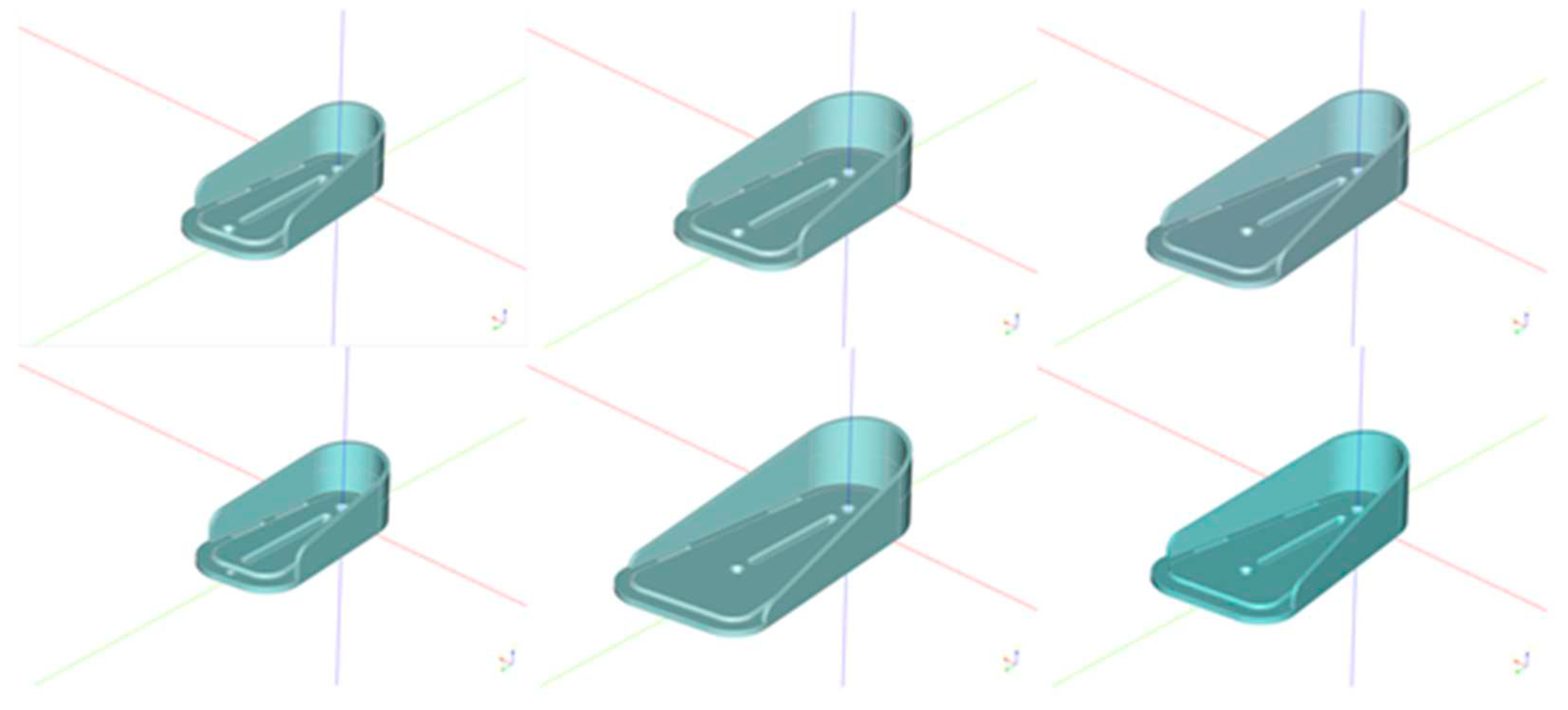
Figure 3.
Personalised footrest value chain. The design process begins with a contour of the patient’s show, the associated anthropometric dimensions are extracted which then drive the design of a parametric footrest CAD model. Alt Text: This figure summarizes the steps undertaken for the design of footrests.

Figure 4.
Running in the back, a Python script running in the environment of CADQuery library receives as input the extracted dimensions and generates a watertight 3D model of the footrest component. Alt text: This figures shows how the 3D model I generated from the received anthropometric measurements.
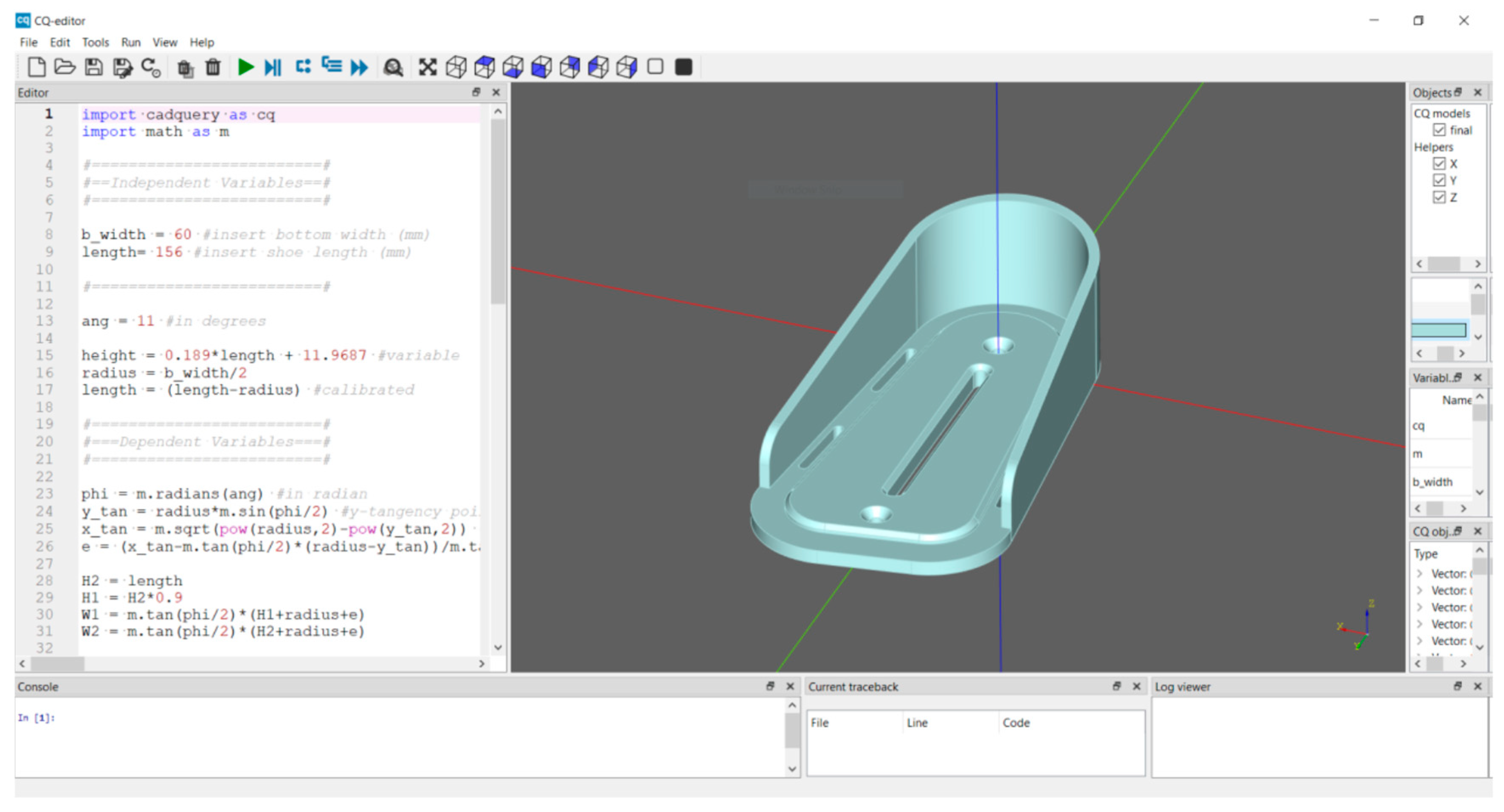
Figure 5.
Principle dimensions and independent design variables extracted by the patient’s anthropometry. Alt text: The figure shows the measurements that need to be computed to be able to design the footrest.
Figure 5.
Principle dimensions and independent design variables extracted by the patient’s anthropometry. Alt text: The figure shows the measurements that need to be computed to be able to design the footrest.
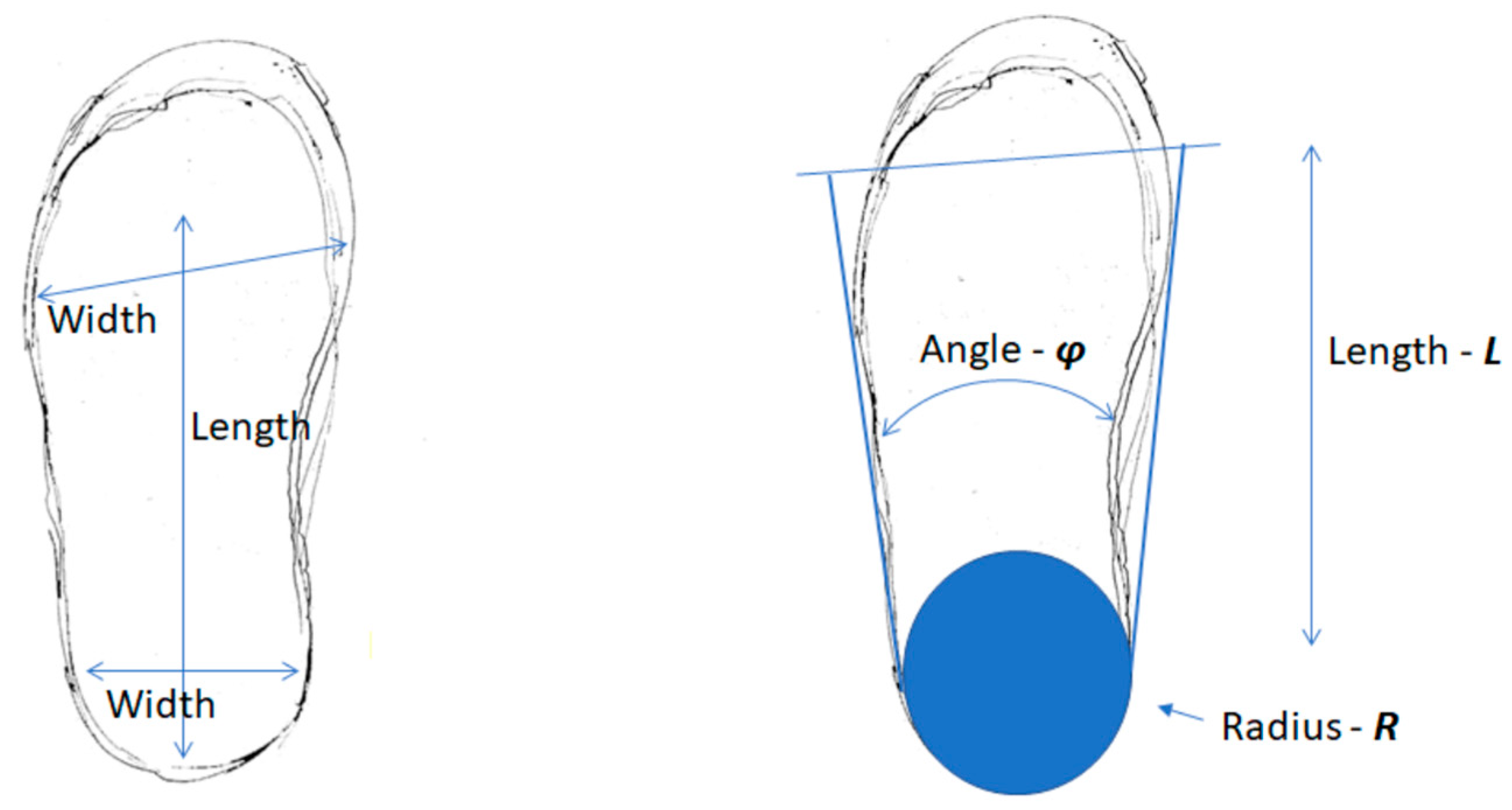
Figure 6.
The Web 3D Modelling Component can be accessed through the web. The interconnections with the core components have been put in place and the tool can be used to provide manufacturable models of the footrest component. Alt Text: This figure shows the web interface for accessing the 3D modelling component.

Figure 7.
Footrest design customisation implementation. Alt Text: This figures shows how computer vision and machine learning are combined to extract the antropometric measurements.
Figure 7.
Footrest design customisation implementation. Alt Text: This figures shows how computer vision and machine learning are combined to extract the antropometric measurements.
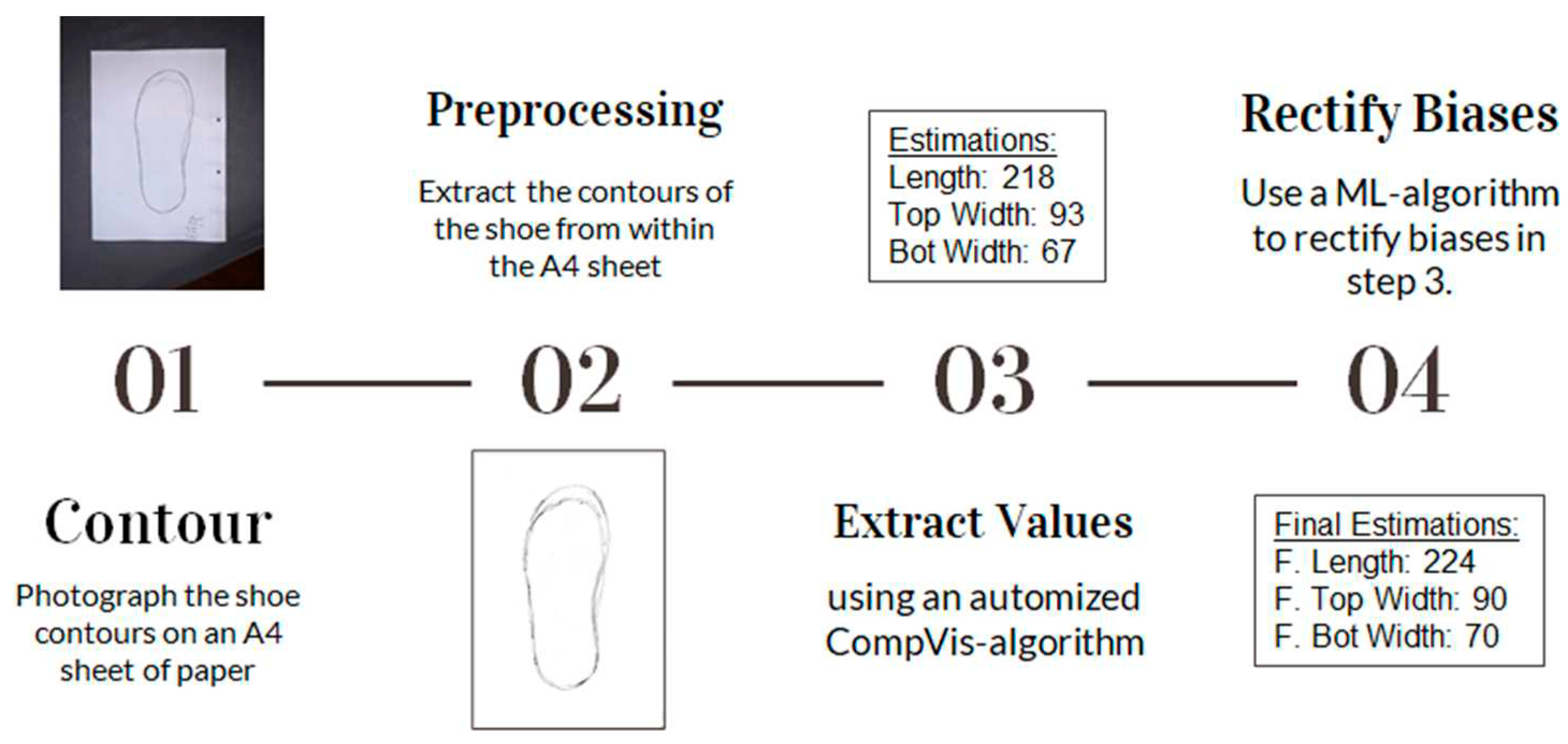
Figure 8.
Shoe’s contour detection. Alt text: Examples of shoes’ contours used in the footrest design.
Figure 8.
Shoe’s contour detection. Alt text: Examples of shoes’ contours used in the footrest design.
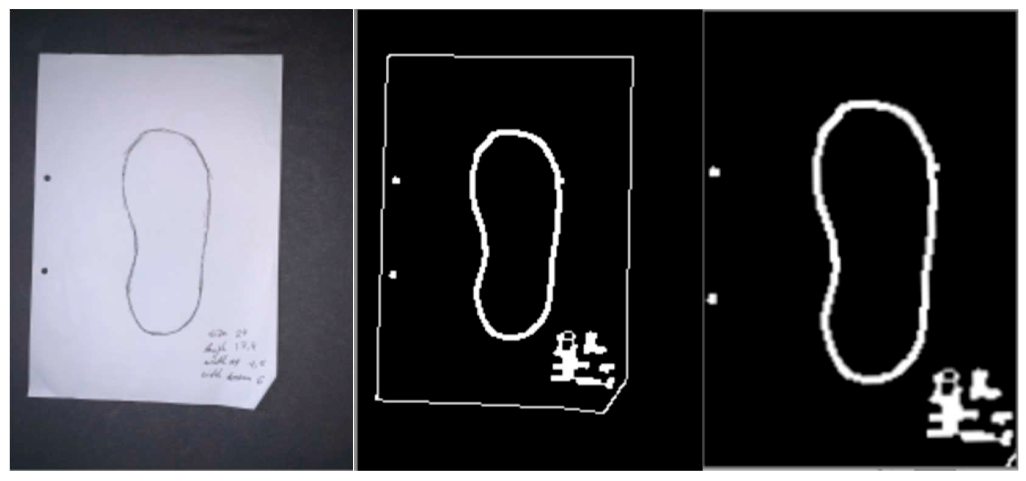
Figure 9.
Shoe length extraction. Alt Text: These figures show how the shoe length is extracted.
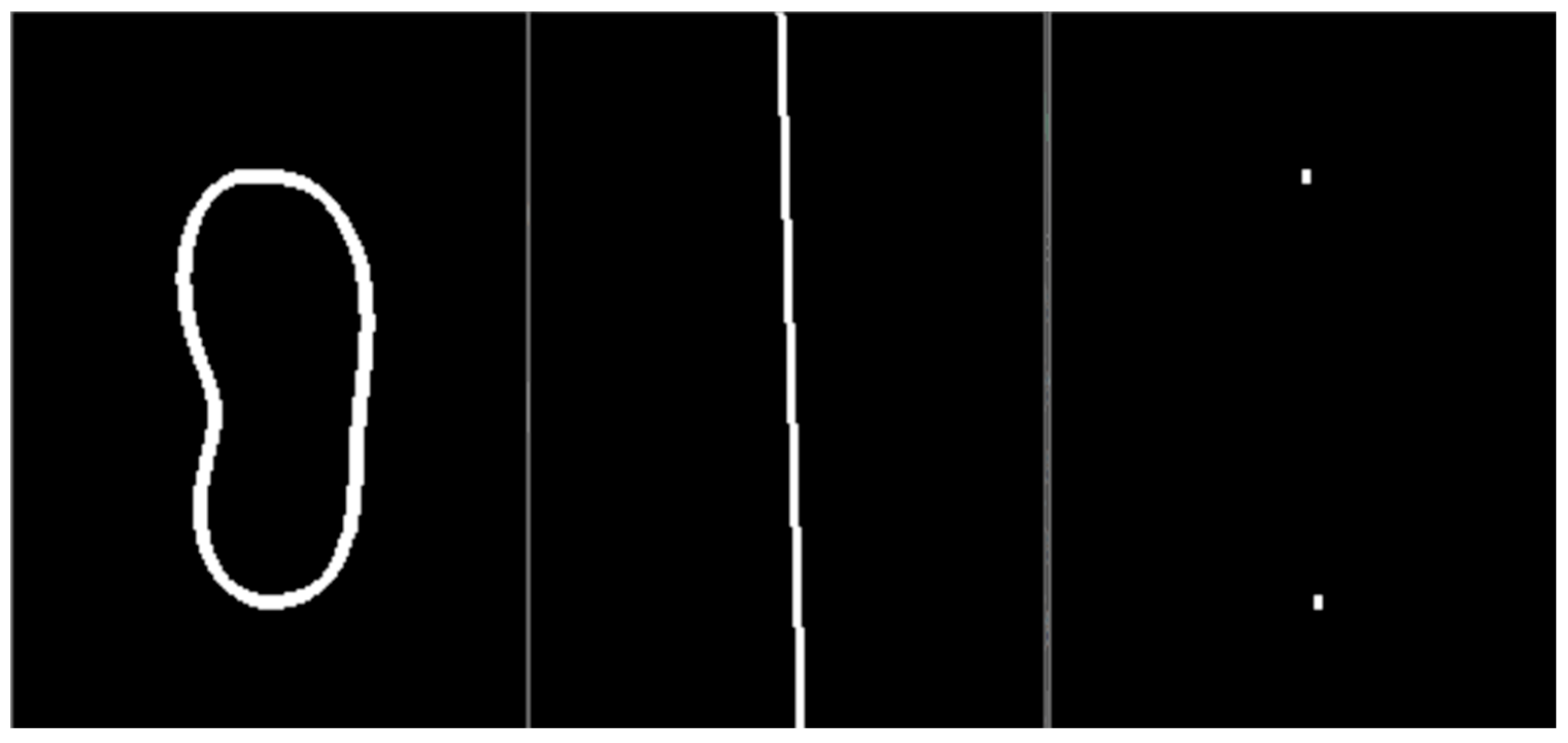
Table 1.
Overview of ML Algorithms used in AM applications.
| Production Stage | Implemented Functions | Examples of ML techniques used |
|---|---|---|
| Design |
|
Hierarchical clustering, SVM, NNs, genetic algorithms |
| AM process and performance optimisation |
|
Self-organizing maps, Back propagation NN, Gaussian process regression, polynomial regression |
| IN-SITU process monitoring and control Post-process monitoring and control |
|
KNN, Bayesian classifier, PCA, SVM, Spectral CNN |
| Quality assessment |
|
KNN, Decision tree, Augmented layerwise spatial log Gaussian Cox process (ALS-LGCP) |
Disclaimer/Publisher’s Note: The statements, opinions and data contained in all publications are solely those of the individual author(s) and contributor(s) and not of MDPI and/or the editor(s). MDPI and/or the editor(s) disclaim responsibility for any injury to people or property resulting from any ideas, methods, instructions or products referred to in the content. |
© 2023 by the authors. Licensee MDPI, Basel, Switzerland. This article is an open access article distributed under the terms and conditions of the Creative Commons Attribution (CC BY) license (http://creativecommons.org/licenses/by/4.0/).
Copyright: This open access article is published under a Creative Commons CC BY 4.0 license, which permit the free download, distribution, and reuse, provided that the author and preprint are cited in any reuse.


