Submitted:
11 May 2023
Posted:
12 May 2023
You are already at the latest version
Abstract
In this paper, we have proposed an effective metasurface design to accomplish cloaking of equilateral patch antennas and their array configuration. As such, we have exploited the concept of electromagnetic invisibility, employing the mantle cloaking technique with the intention to eliminate the destructive interference ensuing between two distinct triangular patches situated in a very congested arrangement (sub-wavelength separation is maintained between the patch elements). Basically, we demonstrate that implementation of the planar coated metasurface cloaks onto the patch antenna surfaces compels them to become invisible to each other, at the intended frequencies. In effect, an individual antenna element does not sense the presence of the other, in spite of being in a rather close vicinity. We also exhibit that the cloaks successfully reinstate the radiation attributes of each antenna in such a way that it emulates their respective performance in an isolated environment. Moreover, we have extended the cloak design to an interleaved one dimensional array of the two patch antennas and it is shown that the coated metasurfaces assure efficient performance of each array in terms of their matching as well as radiation characteristics, in turn, enabling them to radiate independently for various beam-scanning angles.
Keywords:
cloaking
; decoupling
; metasurfaces
; mutual interference
; patch antennas
1. Introduction
The idea of invisibility has never ceased to amaze the human society and thanks to the incessant efforts and multiple decades’ worth work of the scientific community, ‘invisibility’ is no longer a fictional concept. In particular, the advancement of metamaterials and metasurfaces led to the emergence of electromagnetic invisibility, as one of its most alluring applications. Consequently, several approaches were developed in the last few decades, to achieve electromagnetic cloaking. Primarily, the objective of a cloaking device is to make an object undetectable to the external sensors over a desired frequency range. Although, each of the reported eminent cloaking methods serve the purpose of inducing electromagnetic invisibility for the intended object, they come with their own set of advantages and limitations. As such, they should be properly selected, keeping the application of interest in mind. For example, one of the acclaimed techniques, transformation-based cloaking [1,2,3,4], uses the principle of bending and rerouting electromagnetic waves around the concealed object. The fact that the object does not interact with the propagating electromagnetic energy, no scattering is produced by the object, meaning it is truly invisible. Despite being an exquisite way of cloaking, it suffers from several constraints, such as narrow bandwidths [5], inhomogeneous and anisotropic permittivity and permeability distributions and inherent sensitivity to small fabrication tolerances. Another prevalent approach called transmission-line networks method [6,7,8], guides the incident electromagnetic field through a network of transmission lines that is designed to be impedance-matched to free space. Although, in principle, the cloaks can be made extremely broadband, the main drawback of this cloaking technique is that the cloaks are inherently bulky and massive. Another important limitation of the cloaking methods mentioned so far is that they are impractical for sensing and antennas applications, owing to the electromagnetic isolation of the concealed object, i.e., it is unable to transmit or receive electromagnetic energy. In this regard, radically different cloaking methods, exploiting the scattering cancellation principle, are utilized, like plasmonic cloaking and mantle cloaking. Plasmonic cloaking [9,10,11,12,13,14] utilizes bulk isotropic and homogeneous low- or negative-index materials to suppress the dominant scattering mode of the object to be cloaked and is best suited for applications at optical frequencies. Since it relies on bulk volumetric metamaterials, often comparable with the size of the object to be cloaked, it may prove impractical in applications that employ dense environments with many closely spaced objects. At microwave frequencies, the mantle cloaking approach is preferred [15,16,17,18,19,20] and is implemented by using ultrathin conformal metasurfaces made of patterned, yet simple, metallic surfaces. A comprehensive review of the most compelling works in the field of electromagnetic invisibility is presented in [21]. With mantle cloaks, invisibility is induced by the ultrathin metasurfaces by cancelling out the fields scattered by the object to be concealed. This means that the object is not isolated from the surrounding environment, which makes mantle cloaking method suitable for sensing and antenna applications at microwave frequencies. As shown in in [22,23], mantle cloaks have been utilized to remove the mutual blockage between tightly spaced antennas. Moreover, the development of mantle cloaks for the cylindrical configurations eventually facilitated cloaking of popular antenna structures, such as freestanding dipole antennas [24], planar microstrip monopole antennas [25,26], and also simple slot antennas [27]. The uniquely modeled mantle cloaks are also known to bring about cloaking effect among the neighboring antennas in a way that they do not perceive each other [28,29]. Recently, mantle cloaking approach has also been implemented at low-terahertz (THz) frequencies using graphene-based metasurfaces [30,31,32,33]. In a typical fashion, even at low-THz frequencies, graphene-based mantle cloaks are used to reduce the destructive interferences between the planar antennas [34] and strip dipole antennas [35]. Additionally in [36,37], wideband cloaking using mantle cloaks has been achieved for microstrip monopoles. In [38,39,40], design of circuit-loaded metasurfaces to achieve waveform-selective invisibility is presented, in which waveform-selective cloaking devices enable to make an antenna invisible/visible for either short pulses or continuous waves; leading to new invisibility devices characterized by advanced functionalities. As a part of recent works, at microwave frequencies, mantle cloaking method has been used to decouple and cloak interleaved arrays of two monopole antennas [41,42,43,44], and in [45], a solution for minimizing the electromagnetic interference among multiple monopole antennas in a restricted space is presented. It is further protracted to 1D and 2D configurations of microstrip dipole arrays [46]. A method to improve the cloaking performance of a wideband mantle cloak is presented in [47]. The mantle cloaking method has also been used for cloaking of electrically large objects [48]. Very recently, a novel cloaking technique for bow-tie antenna and its array configurations was proposed [49], wherein the surface of the bow-tie antennas are coated with specific metasurfaces to ensure efficient performance of the closely arranged bow-tie antennas.
Motivated by the cloak design in [49], we put forth a metasurface cloak structure for the equilateral triangular patch antennas to reduce the electromagnetic interference arising due to the close proximity of two distinct patches, operating at neighboring frequencies. In this paper, through various simulation results, we manifest that when the top surface of each triangle patch is coated with our proposed metasurface, they are decoupled from each other in the near-field. Besides this, the far-field radiation patterns are also rehabilitated as if each antenna were operating in an isolated environment. We have further extended the cloak design to one-dimensional interleaved array configuration of the aforementioned triangular patches, wherein we demonstrate efficient performance of each array, thereby claiming that a fixed array dimension commonly assigned for only one array is now adept at accommodating two different phased arrays, which can conceivably lead to practical applications with space restrictions. The uniqueness of our cloak design stems from the fact that it utilizes a simple planar structure (in contrast to the more complicated elliptical or circular cloaks that have been employed in the reported literature [22,23,24,25,26,27,28,29]) coated directly onto the antenna surface and brings about cloaking of an electrically large area (side length of the triangular patches is equivalent to approximately a third of the wavelength corresponding to the resonance frequency within dielectric medium). The modeling of the antennas and cloak designs as well as all the numerical full-wave simulations presented in this paper are obtained with the CST Microwave Studio [50].
2. Design of Coated Metasurfaces for Triangular Patch Antennas
In our analysis, we take into consideration two independent simple equilateral triangular patch antennas–Patch I and II, designed such that they radiate at frequencies GHz and GHz, respectively (see Figure 1). These coaxially fed patch antennas are devised on a substrate with thickness mm and dielectric permittivity. From Figure 1, the side lengths for the triangular patch antennas are mm and mm. These two isolated triangular antennas are investigated individually and their radiation characteristics are recorded; this scenario is represented as the isolated case in our analysis.
The triangular patches are then placed in an extremely close proximity on a single dielectric substrate (see Figure 1 (c), length mm and width mm) to manifest the destructive interference effects as a direct consequence of mutual coupling between the two patches. Notice that the patches are not cloaked and are located at a sub-wavelength separation of mm, where is the free space wavelength for the frequency. As expected, the mutual interference deteriorates the radiation properties of both the patches in the near-field as well as the far-field (demonstrated in the simulation results in section 3). For reference, we name this instance as the uncloaked coupled case. Now, we endeavor to eliminate the destructive effects of mutual coupling by implementing the corresponding coated metasurface cloaks onto each of the triangular patches; this is referred to as the cloaked decoupled case (see Figure 2 for the conceptualized schematic diagrams). To begin with the design of these metasurfaces, we first cover the entire top surface of each antenna with a supporting dielectric material; from Figure 2 (b), thickness mm and mm, and permittivity and, for Patch I and Patch II, respectively.
Next, we place a perfect electric conductor (PEC) patch directly on top of these dielectric materials. Observe that there are thin slots cut into the PEC surface, making it appear like a slotted structure (slot widths are mm, and the spacing between the slots are set as mm, mm and mm). For our design, the optimum values for each of the cloak parameters was chosen by conducting extensive parametric analysis (i.e., by varying one parameter at a time within a certain acceptable range). It was also revealed through the parametric analysis that among the numerous cloak parameters, the thickness of the dielectric materials and the placement of the slots on the PEC play a crucial role in bringing about the cloaking effect at the desired frequencies. From our observations of the simulation results, it is our understanding that this particular cloak construct induces the surface currents on the metasurface in the direction opposite to the that of the currents on the patch antenna surface; this indicates the presence of anti-phase surface currents on the metasurface, which is responsible for the cancellation of the scattered fields generated by each antenna at their respective cloaking frequency. We would like to emphasize an important trait of our cloak design. The metasurface cloak coating a particular triangular patch does not perturb the matching and radiation aspects of the antenna at its resonance frequency; instead its ability to suppress electromagnetic interference is reflected at the cloaking frequency of the antenna (in our cases, cloaking frequency for a respective antenna refers to the resonance frequency of the neighboring antenna). For instance, let us consider the characteristics of the uncloaked and cloaked configurations of Patch I in the isolated scenario. To support our abovementioned claim, we have presented the plots for total efficiencies and the cross-sectional electric field (E-field) distribution plots in Figure 3. Note that the resonance frequency for Patch I is GHz and the cloaking frequency is GHz (which is the resonance frequency of Patch II). From Figure 3 (b), we can see that the total efficiency of the cloaked Patch I remains exactly equal to that of the uncloaked case at its resonance frequency ( GHz), whereas it drops to zero at the cloaking frequency ( GHz), indicating that the cloak allows efficient performance of Patch I at its own frequency but makes it a poor radiator at the frequency of the neighboring antenna. Through the E-field distributions in Figure 3 (c) and (d), we establish that the radiation patterns of the uncloaked and cloaked Patch I at GHz are very much similar, thus corroborating the fact that the coated metasurfaces do not interfere with the radiation aspect of the antenna at its resonance frequency. Similar observations can be made for Patch II.
In the next section, we document several results obtained through CST simulation software to showcase the decoupling and cloaking effects of the coated metasurfaces for the closely packed triangular patches.
3. Simulation results for Decoupling and Cloaking of two Triangular Patch Antennas
First off, we demonstrate the scattering cancellation action of our proposed cloak design. Let’s consider the cloak structure for each patch antenna, e.g., Patch I in the presence of a transverse magnetic (TM) polarized plane wave propagating normally to the cloak surface (the schematic is shown in Figure 4 (a)). The total radar cross-section (RCS) plot depicted in Figure 4 (b) shows a remarkable reduction in the magnitude of the scattering width for the cloaked triangular Patch I (magnitude decrement of 9 dB is recorded) as compared to that of its uncloaked counterpart at the cloaking frequency, i.e., GHz. This basically indicates that the cloaked Patch I is forced to become invisible at GHz. Moreover, through the snapshots of the E-field distributions, we see tremendous scattering around the edges of Patch I at its resonance frequency, i.e., at GHz (evident by the distortion of the fields around the patch edges, see Figure 4 (c)); whereas at its cloaking frequency ( GHz), the metasurfaces seemingly eliminate the field scattering around the edges of Patch I (evident by undisturbed passage of the fields through the patch in Figure 4 (d)). An analogous behavior is observed for the case of cloaked Patch II; however the results have not been shown here for the sake of brevity.
The S-parameter plots are shown in Figure 5 (a) and (b), along with the total efficiencies plotted in Figure 5 (c) and (d) to emphasize on the decoupling action of the metasurface cloaks, and the E-field distribution contours (see Figure 6) serve to further validate this claim. It is apparent from Figure 5 (a), that magnitudes of the mutual coupling parameters (denoted by and ) are greater than dB at both and, for the uncloaked coupled case, indicating a very strong coupling between Patch I and II. We also clearly see that the matching characteristics for Patch I is severely degraded, even at its resonance frequency, i.e., at 4.5 GHz (observe the black curve in Figure 5 (a)). For the cloaked decoupled case however, there is a marked reduction in the mutual coupling magnitude (see Figure 5 (b), where a decrement of almost 15 dB in both and is observed at as well as). Also in Figure 5 (b), note that dB at frequency (clear implication that Patch I is decoupled at), and dB at frequency (implying that Patch II remains decoupled at). Likewise, we have also compared the plots for total efficiencies of each of the triangular patches in the isolated, uncloaked and cloaked scenarios, as depicted in Figure 5 (c) and (d). The total efficiency in CST is computed using the following expression: ηtotal = η, where ηtotal denotes total efficiency, Γ is the reflection coefficient ( or) and η signifies the radiation efficiency. A remarkable drop in total efficiencies is recorded for both the patches in their uncloaked configurations (examine the red curves in Figure 5 (c) and (d), the total efficiency reduces by 20% and 25% approx. for Patch I and II, respectively). Nevertheless, the total efficiencies of each patch antenna are evidently restored for the cloaked case (observe the blue curves in Figure 5 (c) and (d)); the recovered efficiencies being comparable to the total efficiencies of their respective isolated counterparts. Another highlighting behavior is that even though the total efficiency of a cloaked patch stays unchanged at its own resonance frequency, it is significantly lowered at the frequency of the neighboring patch antenna.
Along with this, we have presented a cross-sectional view of the E-field distributions in Figure 6, to serve as a comparison between the radiation behavior of the uncloaked and cloaked triangular patches, placed in close proximity. In Figure 6 (a) and (b), Patch I (port I) is active and Patch II is kept passive. Let us observe the contours in Figure 6 (a); it is obvious that mutual coupling is rampant due to the considerable power coupling seen from the input port of Patch I (port I) to the neighboring port II (indicated by a high concentration of fields at port II, shown by the red color). On the contrary, it is obvious that the coated metasurfaces eliminate the power coupling from port I to the input port of Patch II (see the cloaked case in Figure 6 (b)), thus accentuating the decoupling capability of the cloak. In a similar fashion, Figure 6 (c) and (d) represents the uncloaked and cloaked cases, respectively, when Patch II is excited and Patch I is inactive and similar deductions can be made for the coated cloak structure. Finally, polar plots for the realized gain is presented in Figure 7 for each triangular patch antenna at two planes of reference- namely (XOZ plane) and . The main lobe gain of both the patches in its isolated scenario is around 7.5 dBi. The gain patterns of both Patch I and II, in the uncloaked coupled scenario, are severely deformed (apparent from the solid red curves in Figure 7). Nonetheless, an apparent total restoration of the realized gain patterns is clearly observed for both the patches at their respective planes of reference, when the patches are cloaked by the proposed metasurfaces (see the cloaked decoupled case shown by the solid blue curves in Figure 7).
Subsequently, we maintain our claim that the metasurface designed for Patch I makes it a poor radiator by eliminating its scattering residual at the designated frequency of Patch II, and vice versa. It follows that the presence of the metasurfaces leads to the suppression of the far-field coupling as well between the antennas. In the next section, we demonstrate the cloaking capability of our coated metasurface design when it is protracted to an interleaved array of the two triangular patches.
4. Decoupling and Cloaking of the Interleaved Triangular Patch Arrays
We extend the cloaking design specified in the above section to an interleaved phased array of the two triangular patch antennas, arranged linearly on a substrate (thickness mm and permittivity) along the x-axis, as shown in Figure 8. As per the design configurations in Figure 8, we have considered four elements each for Patch I and Patch II in the linear array structure. Array I comprises of all Patch I elements, and are spatially separated by a distance of mm, whereas the elements of Array II consists of Patch II antennas, and are positioned in an upside-down fashion, right next to the elements of Array I at distance of . In a typical manner, such close proximity of all these uncloaked patch elements causes a strong destructive interference in the array performance.
It follows that when two arrays are closely packed, the neighboring antenna elements of the arrays are strongly coupled, degrading the total efficiency as well as the realized gain of each participating array. To minimize this detrimental effect, we employ a similar cloaking approach as discussed in section 2 to our array configuration, wherein the array elements are coated by the respective planar metasurface cloaks, explicitly tailored for the individual triangle patches. The schematic for the cloaked array configuration is illustrated in Figure 8 (b). To demonstrate the decoupling effect, we present the total efficiencies plot for each array in Figure 9. Evidently, the total efficiency decreases substantially for the uncloaked arrays (shown by the red curves in Figure 9 (a) and (b), approximately, 30% and 45% reduction in total efficiencies is recorded for Array I and II, respectively). For the cloaked arrays however, the total efficiencies are greatly improved, almost emulating the efficiency of the corresponding array in the isolated scenario. The E-field plots for the array environment, shown in Figure 10, provides an additional proof of the decoupling effect of the metasurface cloaks. Figure 10 (a) and (b) show comparison for different cases of the field plots when Array I is active (ports 1, 3, 5 and 7 are excited) and Array II is inactive. Similarly, comparison for uncloaked and cloaked scenarios of the field plots when Array II is active (ports 2, 4, 6 and 8 are excited), keeping Array I inactive, is shown in Figure 10 (c) and (d). For the uncloaked cases, a distinct coupling between the neighboring elements of the interleaved arrays is visible, which in turn hampers the far-field radiation capabilities of each individual array. The mutual coupling assuredly reduces when the antenna elements are coated by the suitable metasurface cloaks, thereby guaranteeing reduction of the destructive interference between the neighboring elements of two distinct arrays, and ensuring constructive far-field coupling between the elements of a particular array.
Therefore, by coating the specific metasurfaces onto each corresponding patch elements (cloaked scenario), the coupling effects are substantially decreased in the near-field and restoration of radiation patterns is noticed in the far-field, thereby vastly improving the overall radiation characteristics of each array.
4.1. Beam Scanning
The metasurfaces are not only engineered with the intention to improve the properties to be comparable with the isolated array, but also to make all the elements of one array invisible to and decoupled from all the elements of the neighboring array. This ensures that the two arrays can operate as if they were isolated from each other, which in turn would enable efficient beam scanning for various scan angles. Based on the well-known formula for determination of phase shift for each antenna element of an array at their resonance frequency, we calculated the range of beam scanning angles for our array configurations. It follows that both the cloaked Array I and II have the capability of faithfully scanning the angles from to in the XOZ plane. The polar plots of the realized gain at different beam scanning angles for Array I and Array II are depicted in Figure 11 and Figure 12, respectively. It is apparent from the polar plots for both arrays that the metasurface cloaks coating the antenna elements of the arrays rehabilitate the realized gain patterns at all the illustrated scan angles.
5. Conclusions
In conclusion, we assert that the proposed simple planar metasurface design has successfully achieved decoupling and cloaking of the equilateral triangle patch antennas and its interleaved phased arrays, when two patch elements are placed within subwavelength distance (extremely small spatial separation is utilized). We substantiate our claim through the numerous simulation results presented in the paper. Hence, we have strived to put forth a design that will lead to densely packed array configurations with vastly improved performance, high efficiency, and beam scanning capabilities. With regards to continuation of this work, we believe that the cloak construct could be modified to induce electromagnetic invisibility in other printed antenna configurations (or a specific active structure) such that they can be rendered undetectable to external sensors and detecting devices. Also, due to the simplicity of the physical design of the cloak structure, our metasurface design is desirable not only in theory, but also feasible for practical fabrications.
Author Contributions
Conceptualization, Shefali Pawar and Alexander Yakovlev.; design methodology, Shefali Pawar; software simulations, Shefali Pawar; validation, Shefali Pawar, Alexander Yakovlev, Harry Skinner, Seong-Youp Suh; investigation, Shefali Pawar; resources, Shefali Pawar and Alexander Yakovlev; data curation, Shefali Pawar; writing—original draft preparation, Shefali Pawar; writing—review and editing, Shefali Pawar, Alexander Yakovlev, Harry Skinner, Seong-Youp Suh; supervision, Shefali Pawar and Alexander Yakovlev; funding acquisition, Harry Skinner, Seong-Youp Suh, Alexander Yakovlev. All authors have read and agreed to the published version of the manuscript.
Funding
This research was funded by the NSF I/UCRC Grant 1822104 and by the Intel Corporation.
Conflicts of Interest
The authors declare no conflict of interest.
References
- J. Pendry, D. Schurig, and D. Smith, “Controlling electromagnetic fields,” Science, vol. 312, no. 5781, pp. 1780–1782, June 2006.
- J. Li, and J. Pendry, “Hiding under the carpet: A new strategy for cloaking,” Phys. Rev. Lett., vol. 101, p. 203901, 2008.
- H. Chen, C. Chan, and P. Sheng, “Transformation optics and metamaterials,” Nat. Mater., vol. 9, no. 5, pp. 387–396, May 2010. [CrossRef]
- A. Vakil, and N. Engheta, “Transformation optics using graphene,” Science, vol. 332, no. 6035, pp. 1291–1294, 2011. [CrossRef]
- F. Monticone, and A. Alù, “Invisibility exposed: physical bounds on passive cloaking,” Optica, vol. 3, no. 7, pp. 718–724, July 2016. [CrossRef]
- P. Alitalo, O. Luukkonen, L. Jylha, J. Venermo, and S. Tretyakov, “Transmission-line networks cloaking objects from electromagnetic fields,” IEEE Trans. Antennas Propag., vol. 56, no. 2, pp. 416–424, February 2008. [CrossRef]
- S. Tretyakov, P. Alitalo, O. Luukkonen, and C. Simovski, “Broadband electromagnetic cloaking of long cylindrical objects,” Phys. Rev. Lett., vol. 103, p. 103905, 2009. [CrossRef]
- P. Alitalo, J. Vehmas, and S. Tretyakov, “Reduction of antenna blockage with a transmission-line cloak,” Eur. Conf. Antennas Propag. (EuCAP), Rome, Italy, April 2011 pp. 2399–2402.
- A. Alù, and N. Engheta, “Achieving transparency with plasmonic and metamaterial coatings,” Phys. Rev. E, vol. 72, p. 016623, 2005. [CrossRef]
- A. Alù, and N. Engheta, “Plasmonic materials in transparency and cloaking problems: Mechanism, robustness, and physical insights,” Opt. Express, vol. 15, p. 3318, 2007.
- A. Alù, and N. Engheta, “Cloaking and transparency for collections of particles with metamaterial and plasmonic covers,” Opt. Express, vol.15, p. 7578, 2007. [CrossRef]
- B. Edwards, A. Alù, M. Silveirinha, and N. Engheta, “Experimental verification of plasmonic cloaking at microwave frequencies with metamaterials,” Phys. Rev. Lett., vol. 103, p. 153901, 2009. [CrossRef]
- M. Guild, M. Haberman, and A. Alù, “Plasmonic cloaking and scattering cancelation for electromagnetic and acoustic waves,” Wave Mot., vol. 48, pp. 468–482, 2011. [CrossRef]
- D. Rainwater, A. Kerkhoff, K. Melin, J. Soric, G. Moreno, G., and A. Alù “Experimental verification of three-dimensional plasmonic cloaking in free-space,” New J. Phys., vol. 143, p. 013054, 2012.
- A. Alù, “Mantle cloak: Invisibility induced by a surface,” Phys. Rev. B, vol. 80, p. 245115, Dec. 2009. [CrossRef]
- P. Chen, and A. Alù, “Mantle cloaking using thin patterned metasurfaces,” Phys. Rev. B, vol. 84, p. 205110, Nov. 2011. [CrossRef]
- Y. Padooru, A. Yakovlev, P. Chen, and A. Alù, “Analytical modeling of conformal mantle cloaks for cylindrical objects using sub-wavelength printed and slotted arrays,” J. Appl. Phys., vol. 112, no. 3, p. 034907, Aug. 2012. [CrossRef]
- L. Matekovits, and T. Bird, “Width-modulated microstrip-line based mantle cloaks for thin single and multiple cylinders”, IEEE Trans. Antennas and Propag., vol. 62, no. 5, pp. 2606–2615, May 2014. [CrossRef]
- Z. Hamzavi-Zarghani, A. Yahaghi, and L. Matekovits, “Analytical design of a metasurface based mantle cloak for dielectric cylinder under oblique incidence”, Int. Symp. Telecomm., Tehran, Iran, Dec. 2018, pp. 65–68.
- H. Mehrpour Bernety, and A. Yakovlev, “Conformal and confocal mantle cloaking of elliptical cylinders using sub-wavelength metallic meshes and patches,” IEEE APS Int. Symp., Memphis, USA, July 2014, pp. 1433–1434.
- S. Vellucci, A. Monti, M. Barbuto, A. Toscano, and F. Bilotti, “Progress and perspective on advanced cloaking metasurfaces: from invisibility to intelligent antennas,” EPJ Appl. Metamat., vol. 7, 2021. [CrossRef]
- A. Monti, J. Soric, A. Alù, F. Bilotti, A. Toscano, and L. Vegni, “Overcoming mutual blockage between neighboring dipole antennas using a low-profile patterned metasurface,” IEEE Antennas Wireless Propag. Lett., vol. 11, pp. 1414–1417, Dec. 2012. [CrossRef]
- J. Soric, A. Monti, A. Toscano, F. Bilotti, and A. Alù, “Dual-polarized reduction of dipole antenna blockage using mantle cloaks,” IEEE Trans. Antennas Propag., vol. 63, no. 11, pp. 4827–4834, Nov. 2015. [CrossRef]
- H. Mehrpour Bernety, and A. Yakovlev, “Reduction of mutual coupling between neighboring strip dipole antennas using confocal elliptical metasurface cloaks,” IEEE Trans. Antennas Propag., vol. 63, no. 4, pp. 1554–1563, April 2015. [CrossRef]
- H. Mehrpour Bernety, and A. Yakovlev, “Decoupling antennas in printed technology using elliptical metasurface cloaks,” J. Appl. Phys., vol. 119, no. 1, p. 014904, Jan. 2016. [CrossRef]
- S. Pawar et al., “Elliptical Metasurface Cloaks for Decoupling and Cloaking of Microstrip Monopole Antennas at 28 GHz and 39 GHz for 5G Wireless Applications,” IEEE APS Int. Symp., Montreal, Canada, July 2020, pp. 805-806.
- S. Pawar, H. G. Skinner, S. -Y. Suh and A. B. Yakovlev, “Cloaking of Slot Antennas at C-Band Frequencies Using Elliptical Metasurface Cloaks,” IEEE Antennas Wireless Propag. Lett., vol.21, pp. 2171-2175, July 2022.
- Z. Jiang, and D. Werner, “Dispersion engineering of metasurfaces for dual-frequency quasi-three-dimensional cloaking of microwave radiators,” Optics Express, vol. 24, no. 9, pp. 9629–9644, April 2016. [CrossRef]
- A. Monti, et al.: “Mantle cloaking for co-site radio-frequency antennas,” Appl. Phys. Lett., vol. 108, no. 11, p. 113502, Mar. 2016. [CrossRef]
- P. Chen, and A. Alù, “Atomically-thin surface cloak using graphene monolayers,” ACS Nano, vol. 5, no. 7, pp. 5855–5863, June 2011. [CrossRef]
- P. Chen, J. Soric, Y. Padooru, H. Bernety, A. Yakovlev, and A. Alù, “Nanostructured graphene metasurface for tunable terahertz cloaking,” New. J. Phys., vol. 15, p. 123029, Dec. 2013. [CrossRef]
- S. Pawar, H. Mehrpour Bernety, and A. B. Yakovlev, “Cloaking of Cylindrical Objects with Graphene-Metasurface Structures for Low-Terahertz Applications”, IEEE APS Int. Symp., Colorado, USA, July 2022, pp. 1366-1367.
- S. Pawar, H. Mehrpour Bernety, and A. B. Yakovlev, “ Graphene-Metal Metasurface for Cloaking of Cylindrical Objects at Low-Terahertz Frequencies”, IEEE Access., vol.10, pp. 130200-130211, Dec. 2022. [CrossRef]
- J. Ghosh, and D. Mitra, “Mutual coupling reduction in planar antenna by graphene metasurface for THz application”, J. Electromagnetic Waves and App., vol. 31, no. 18, pp. 2036–2045, Jan. 2017. [CrossRef]
- G. Moreno, H.Mehrpour Bernety, and A. Yakovlev, “Reduction of mutual coupling between strip dipole antennas at terahertz frequencies with an elliptically shaped graphene monolayer”, IEEE Antenna Wireless Propag., Lett., vol. 15, pp. 1533–1536, Dec. 2015. [CrossRef]
- G. Moreno et al., “Wideband Elliptical Metasurface Cloaks in Printed Antenna Technology,” IEEE Trans. Antennas Propag., vol. 66, no. 7, pp. 3512-3525, July 2018. [CrossRef]
- E. Shokati and, N. Granpayeh, “Wideband cloaking by using inhomogeneous nanostructured graphene metasurface for tunable cloaking in the terahertz regime,” Int. Conf. Millimeter-Wave and Terahertz Tech. (MMWaTT), Dec. 2016, pp. 9-13.
- S. Vellucci, A. Toscano, F. Bilotti, A. Monti, and M. Barbuto, “Towards waveform-selective cloaking devices exploiting circuit-loaded metasurfaces”, IEEE APS Int. Symp., Boston, USA, July 2018, pp. 1861–1862.
- S. Vellucci, A. Monti, M. Barbuto, A. Toscano, and F. Bilotti, “Recent developments in the design of waveform-selective mantle cloaks for antenna applications”, Int. Cong. Artificial Materials (Metamaterials), Espoo, Finland, August 2018, pp. 421–423.
- S. Vellucci, A. Toscano, F. Bilotti, A. Monti, and M. Barbuto, “Design of waveform-selective mantle cloaks for antenna applications”, IEEE APS Int. Symp., Atlanta, USA, July 2019, pp. 1319–1320.
- H. Mehrpour Bernety, A. Yakovlev, H. Skinner, S. Suh and A. Alù, “Decoupling and Cloaking of Interleaved Phased Antenna Arrays Using Elliptical Metasurfaces,” IEEE Trans. Antennas Propag., vol. 68, no. 6, pp. 4997-5002, June 2020. [CrossRef]
- H. Mehrpour Bernety, S. Pawar, H. G. Skinner, S-Y. Suh, A. Alù and A. B. Yakovlev, “How to Decouple and Cloak Interleaved Phased Arrays?”, Int. Congress on Artificial Materials for Novel Wave Phenomena (Metamaterials), New York, USA, Sept. 2020, pp. 403-405.
- S. Pawar et al., “Cloaking and Decoupling of Interleaved Microstrip Monopole Arrays at 28 GHz and 39 GHz Using Elliptical Metasurfaces for 5G Wireless Applications,” IEEE APS Int. Symp., Montreal, Canada, July 2020, pp. 869-870.
- S. Pawar, H. Mehrpour Bernety, H. G. Skinner, S.-Y. Suh, A. Alù, A. B. Yakovlev, “Mantle cloaking for decoupling of interleaved phased antenna arrays in 5G applications,” AIP Conference Proceedings, vol. 2300, no. 1, p.020095, Dec. 2020. [CrossRef]
- D. Lee, “Metasurface cloaks for decoupling electromagnetic interference within highly dense areas,” AIP Advances, vol. 13, p. 045111, April 2023. [CrossRef]
- D. Lee and A. B. Yakovlev, “Metasurface Cloaks to Decouple Closely Spaced Printed Dipole Antenna Arrays Fed by a Microstrip-to-Balanced Transmission-Line Transition,” IEEE Access, vol. 9, pp. 128209-128219, Sept. 2021. [CrossRef]
- M. Bisht, V. Vinubhai, and K. Srivastava, “Analysis and realization of a wideband mantle cloak with improved cloaking performance” J. Electromagnetic Waves and App., pp. 1–14, January 2020.
- H. Younesiraad, M. Bemani, and S. Nikmehr, “Scattering suppression and cloak for electrically large objects using cylindrical metasurface based on monolayer and multilayer mantle cloak approach”, IET Microwaves, Antennas Propag., vol. 13, pp. 278–285, November 2018. [CrossRef]
- D. Lee, “Study of metasurface coated bowtie antenna to decouple closely coupled arrays,” AIP Advances, vol. 12, p. 115108, Nov. 2022. [CrossRef]
- CST Microwave Studio 2019: https://www.cst.com.
Figure 1.
Schematic diagrams for (a) Isolated Patch I, (b) Isolated Patch II, (c) top-view, and (d) side-view of the uncloaked coupled triangular patches.
Figure 1.
Schematic diagrams for (a) Isolated Patch I, (b) Isolated Patch II, (c) top-view, and (d) side-view of the uncloaked coupled triangular patches.
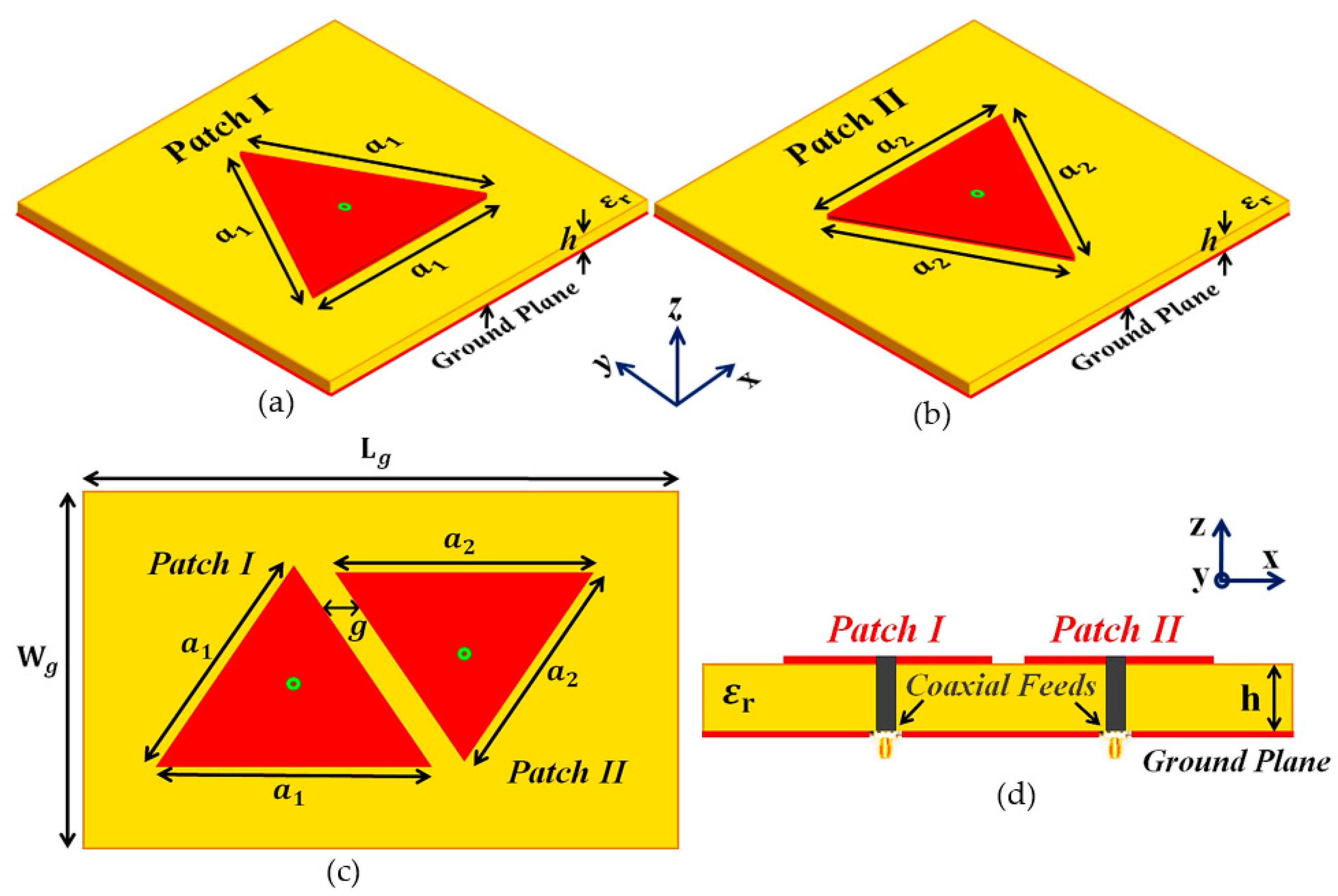
Figure 2.
Schematic diagrams for (a) top-view and (b) side-view of the cloaked decoupled triangular patches.
Figure 2.
Schematic diagrams for (a) top-view and (b) side-view of the cloaked decoupled triangular patches.
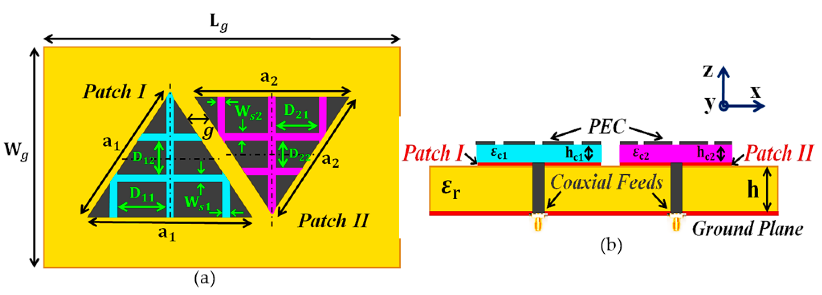
Figure 3.
(a) Cloaked Patch I configuration, (b) plots for total efficiencies, and E-field contours at GHz for (c) uncloaked, (d) cloaked Patch I.
Figure 3.
(a) Cloaked Patch I configuration, (b) plots for total efficiencies, and E-field contours at GHz for (c) uncloaked, (d) cloaked Patch I.
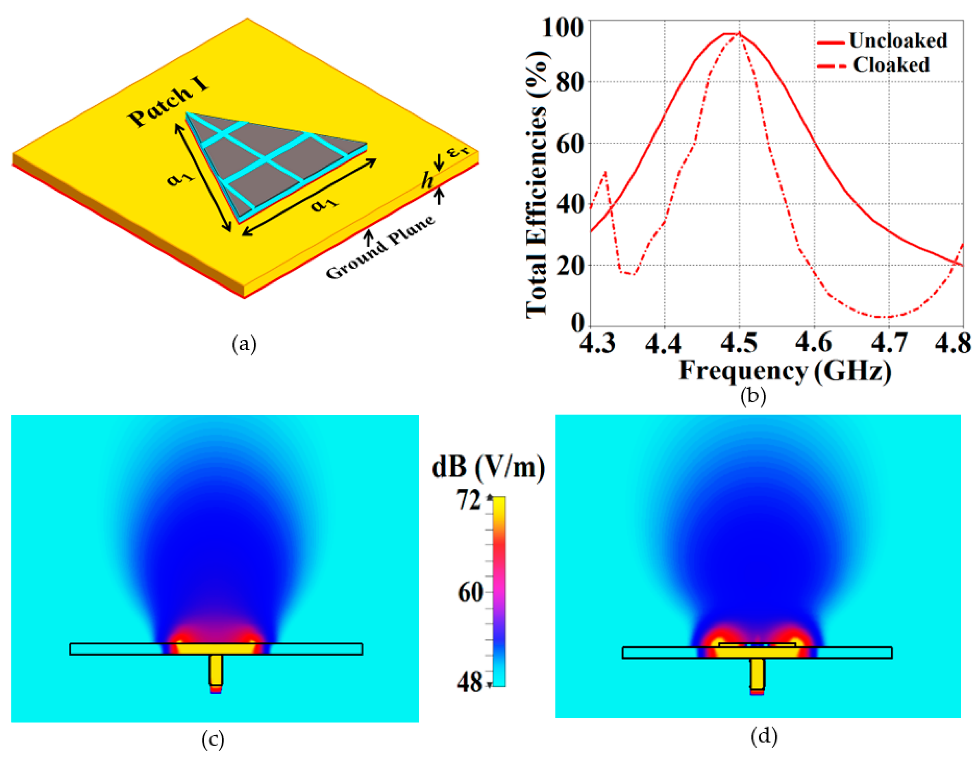
Figure 4.
(a) Cross-sectional view of the cloaked Patch I, (b) Total RCS plot, and E-field distributions for cloaked Patch I (c) at GHz, (d) at GHz for a normally incident TM polarized plane wave.
Figure 4.
(a) Cross-sectional view of the cloaked Patch I, (b) Total RCS plot, and E-field distributions for cloaked Patch I (c) at GHz, (d) at GHz for a normally incident TM polarized plane wave.
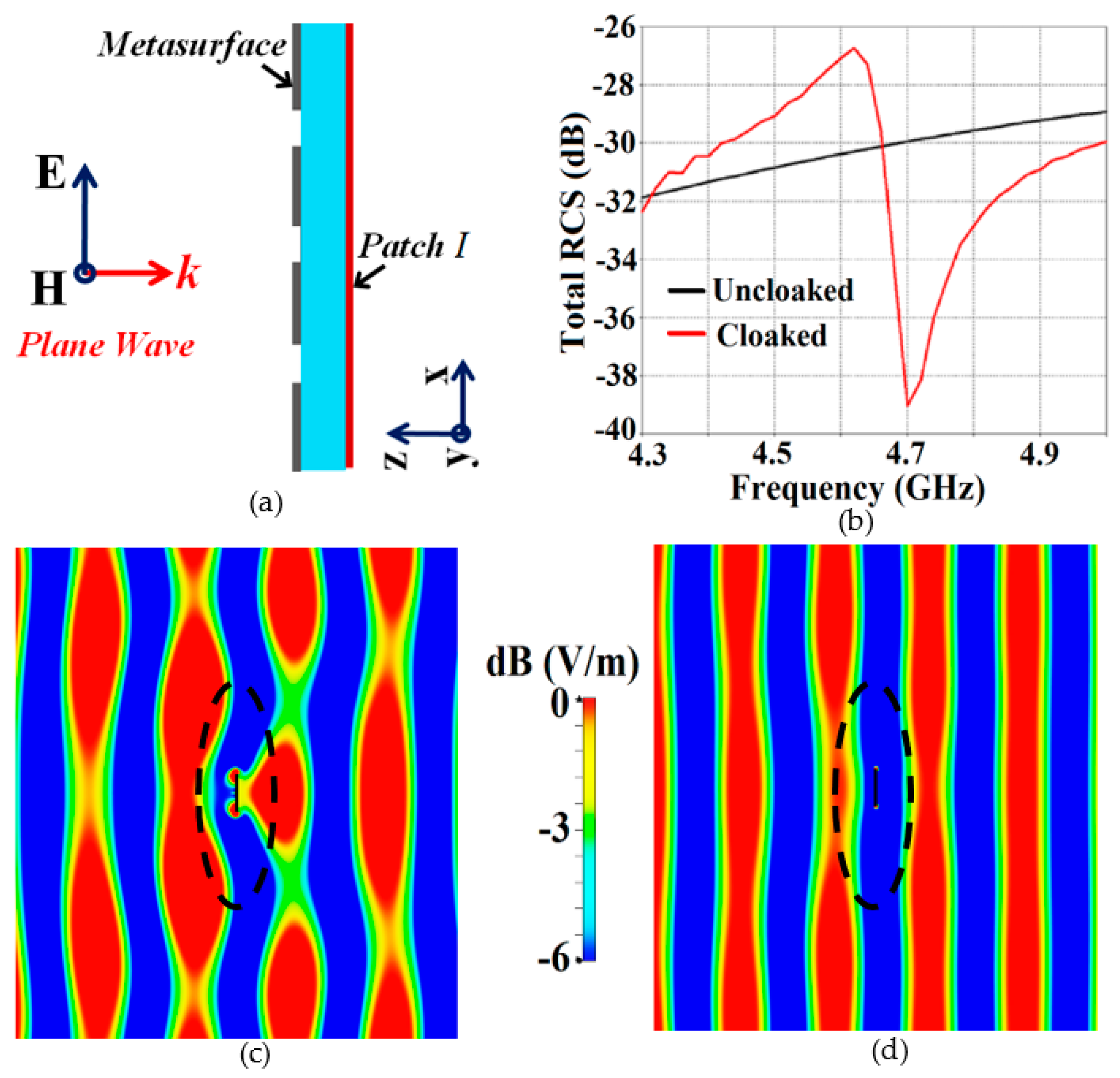
Figure 5.
Plots for S-parameters: (a) uncloaked coupled, (b) cloaked decoupled equilateral triangle patch antennas, and plots for total efficiencies: (c) Patch I is active, (d) Patch II is active.
Figure 5.
Plots for S-parameters: (a) uncloaked coupled, (b) cloaked decoupled equilateral triangle patch antennas, and plots for total efficiencies: (c) Patch I is active, (d) Patch II is active.

Figure 6.
E-field contours for (a) uncloaked, (b) cloaked cases, when Patch I is active, and (c) uncloaked, (d) cloaked cases, when Patch II is active.
Figure 6.
E-field contours for (a) uncloaked, (b) cloaked cases, when Patch I is active, and (c) uncloaked, (d) cloaked cases, when Patch II is active.
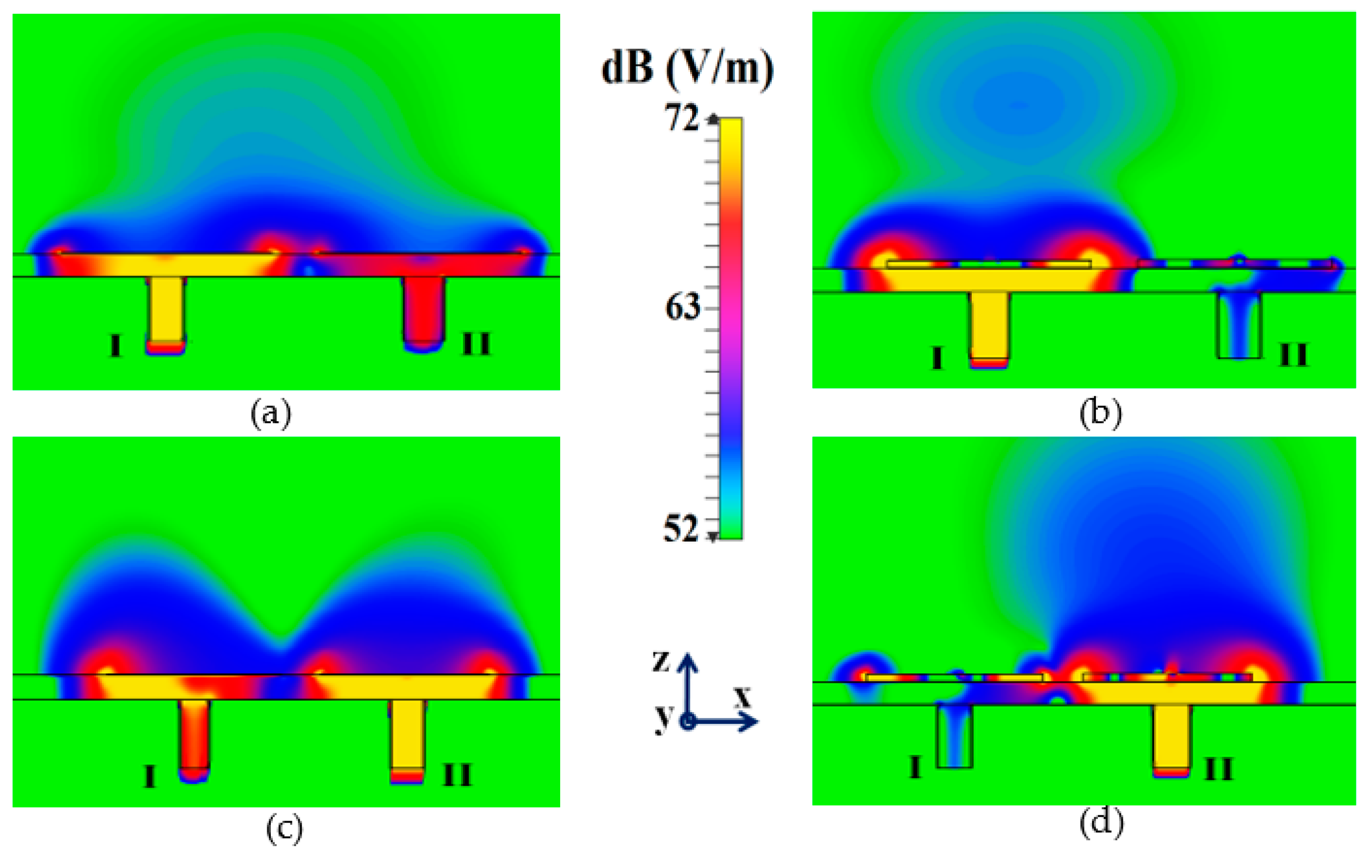
Figure 7.
Realized gain patterns at (a), (b) for Patch I ( GHz), and at (c), (d) for Patch II ( GHz).
Figure 7.
Realized gain patterns at (a), (b) for Patch I ( GHz), and at (c), (d) for Patch II ( GHz).
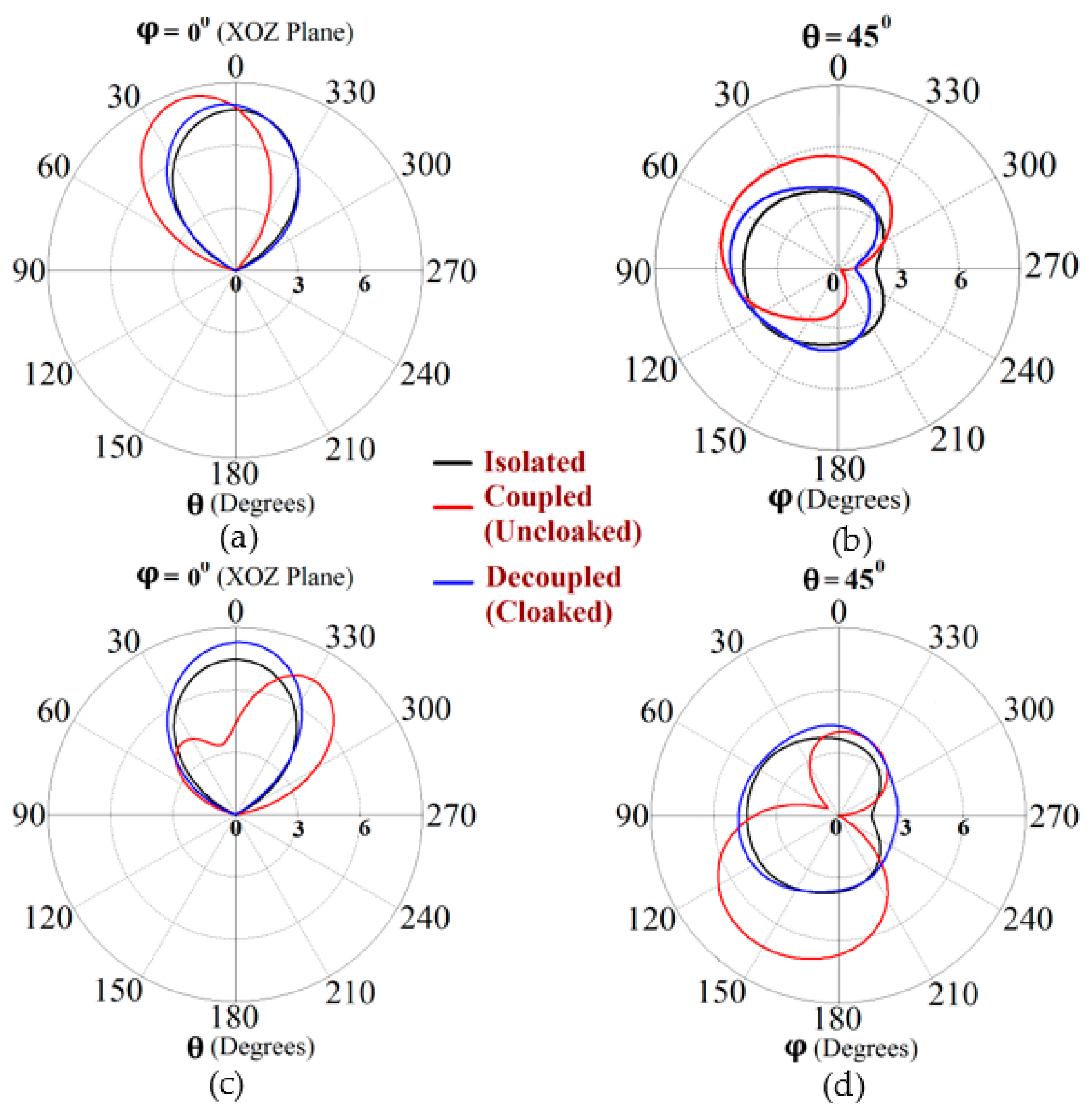
Figure 8.
Conceptualized design configurations of (a) uncloaked and (b) cloaked equilateral triangle patch antenna arrays.
Figure 8.
Conceptualized design configurations of (a) uncloaked and (b) cloaked equilateral triangle patch antenna arrays.
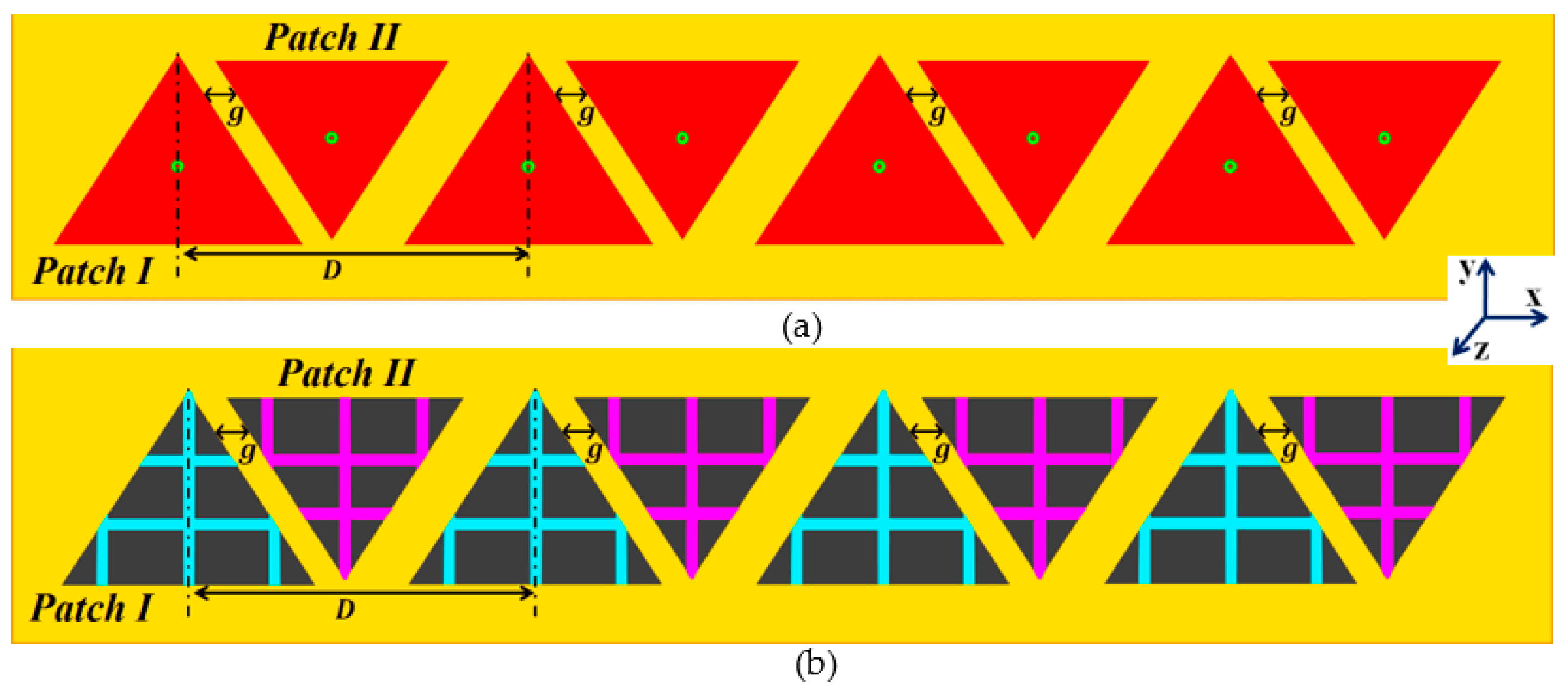
Figure 9.
Plots for total efficiencies: (a) Array I ( GHz) is active and (b) Array II ( GHz) is active.
Figure 9.
Plots for total efficiencies: (a) Array I ( GHz) is active and (b) Array II ( GHz) is active.
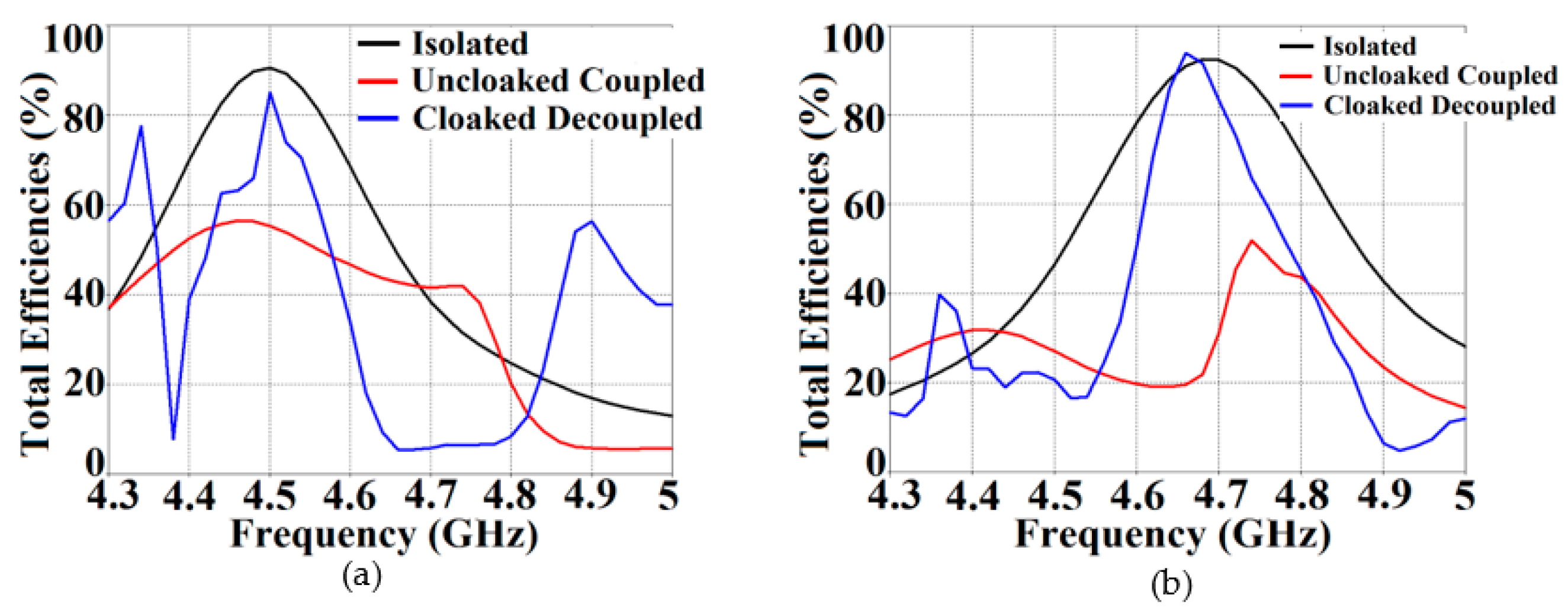
Figure 10.
E-field contours: (a) uncloaked, (b) cloaked patch antenna arrays when Array I is active and (c) uncloaked, (d) cloaked patch antenna arrays when Array II is active.
Figure 10.
E-field contours: (a) uncloaked, (b) cloaked patch antenna arrays when Array I is active and (c) uncloaked, (d) cloaked patch antenna arrays when Array II is active.
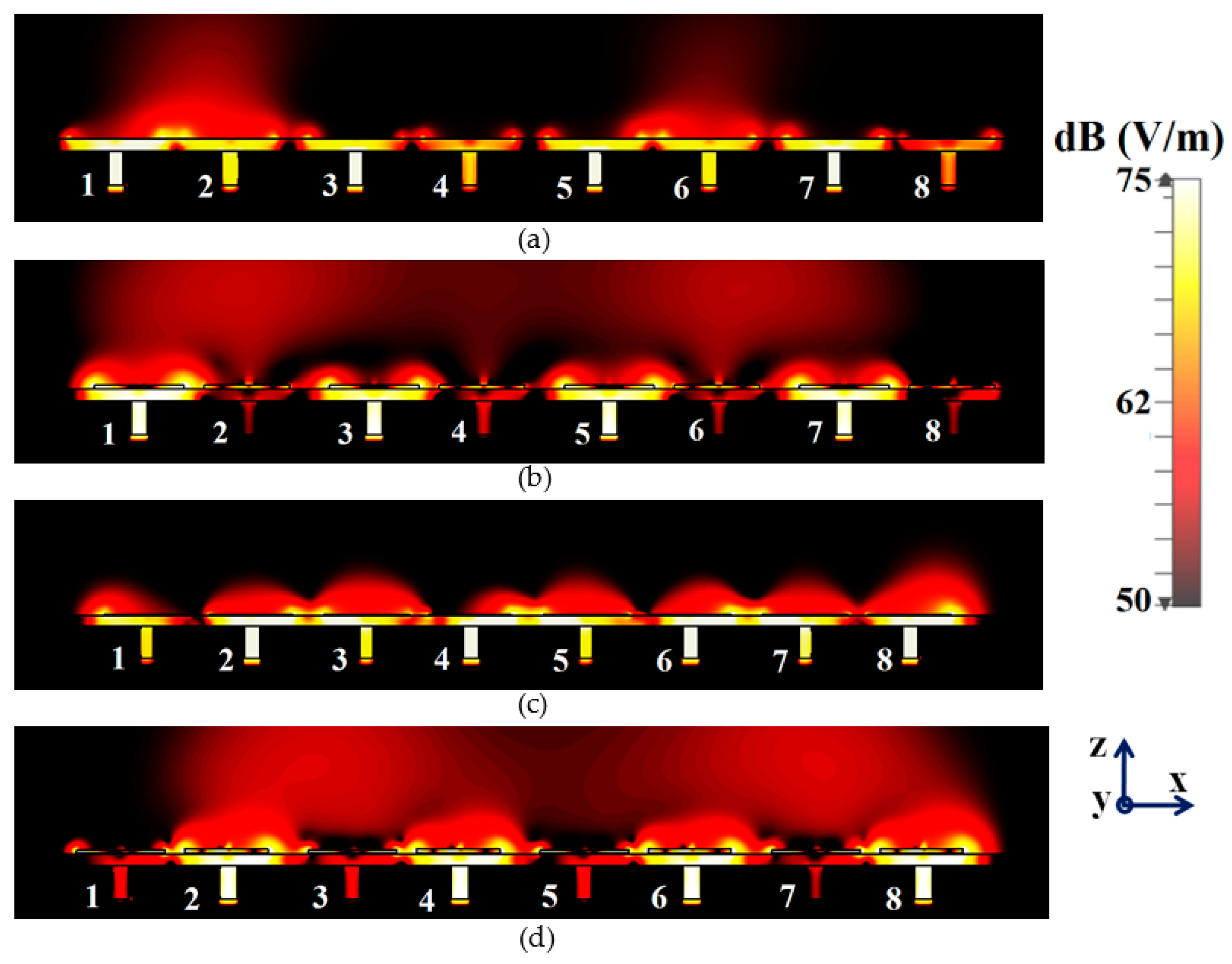
Figure 11.
Realized gain polar plots for Array I ( GHz) at scan angles: (a) , (b) , (c) , and (d) .
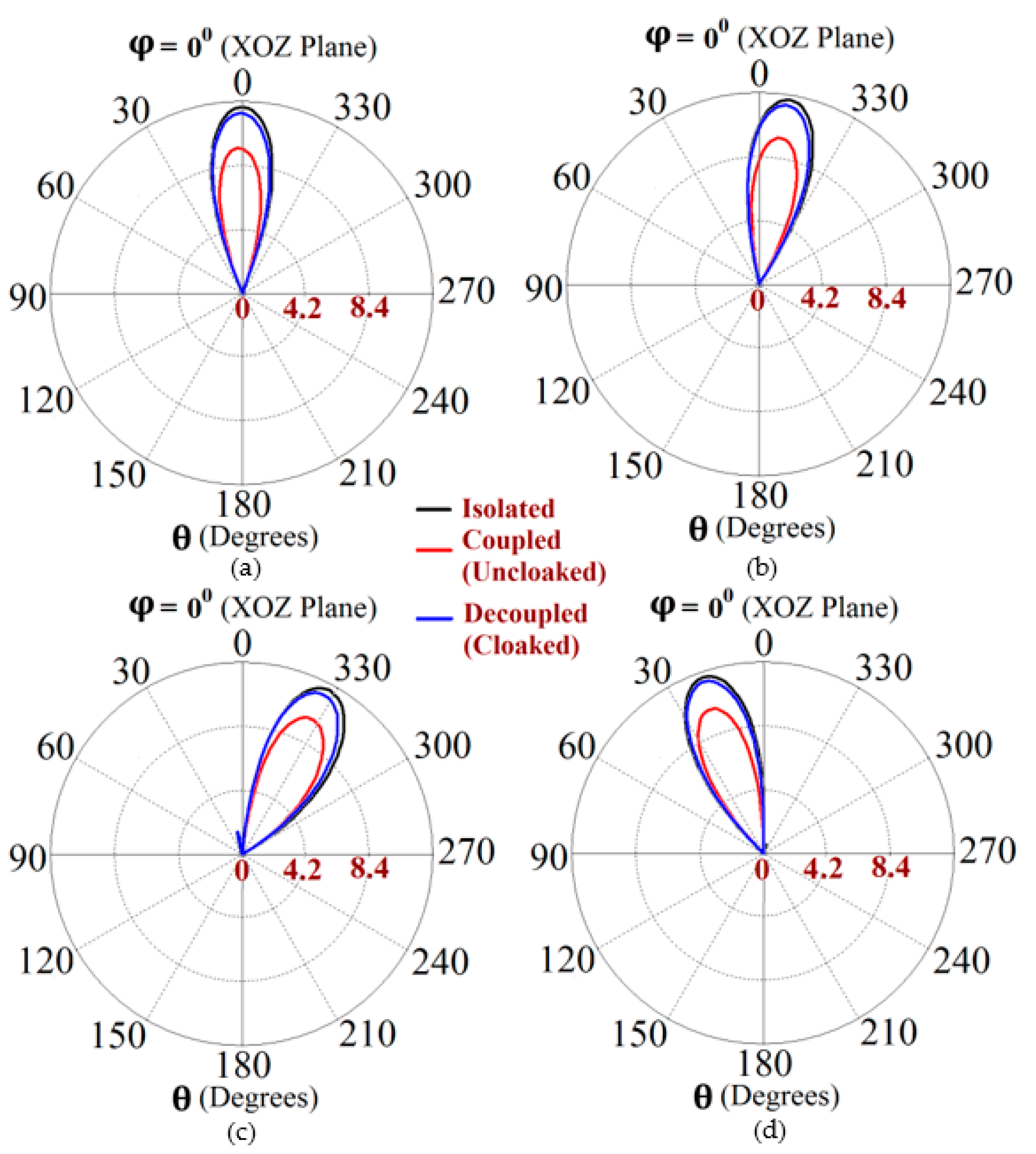
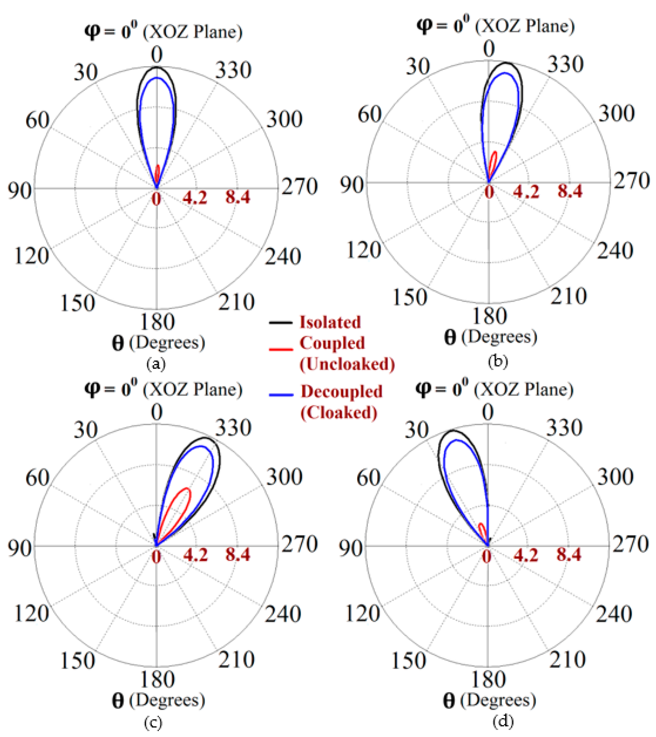
Figure 12.
Realized gain polar plots for Array II ( GHz) at scan angles: (a) , (b) , (c) , and (d) .
Figure 12.
Realized gain polar plots for Array II ( GHz) at scan angles: (a) , (b) , (c) , and (d) .
Disclaimer/Publisher’s Note: The statements, opinions and data contained in all publications are solely those of the individual author(s) and contributor(s) and not of MDPI and/or the editor(s). MDPI and/or the editor(s) disclaim responsibility for any injury to people or property resulting from any ideas, methods, instructions or products referred to in the content. |
© 2023 by the authors. Licensee MDPI, Basel, Switzerland. This article is an open access article distributed under the terms and conditions of the Creative Commons Attribution (CC BY) license (http://creativecommons.org/licenses/by/4.0/).
Copyright: This open access article is published under a Creative Commons CC BY 4.0 license, which permit the free download, distribution, and reuse, provided that the author and preprint are cited in any reuse.


