Submitted:
04 May 2023
Posted:
05 May 2023
You are already at the latest version
Abstract
3D printing with cement-based materials is a promising manufacturing technique for civil engineering applications that already allows for the design and the construction of complex and highly customized structures using a layer-by-layer deposition approach. Usually, in this type of additive manufacturing, a mixture of cement, water, aggregate and additives is extruded through a specific print head and deposited in successive layers to form the desired shape. The extrusion mechanism is one of the most expensive parts of the 3D printer. Also, for low scale 3D printers, based on the shape of the extruder and the geometry limitation of the mixing blade, the 3D mixture is often limited to a narrow range of materials due to the risk of layer splitting or blockage. Therefore, there is a need to develop affordable and feasible alternatives to the current design-fabrication-application approach of 3D printers. In this paper, various new designed mixtures of fiber reinforced mortars that can be 3D printed using only a commercially available screw pump are analyzed based on their fresh properties and mechanical characteristics. The reduced facility requirements in this approach allow 3D-printing to be more available for civil engineering applications. With further innovation in the future, this method and mixtures can be extended for sustainable and economically feasible printing of single-family housing units.
Keywords:
3D printing
; fiber reinforced mortar
; fresh properties
; hardened properties
; additive manufacturing
1. Introduction
Three-Dimensional (3D) printing is a process that enables the manufacture of solid objects, based on a digital model. It involves laying down successive layers of material (e.g., plastic, mortar, clay, metal, ceramic), starting from the base and continuing to the top part of the digital model, until the real object is complete [1]. Nowadays, 3D printing is used in a large variety of industries including civil and mechanical engineering, aerospace and healthcare, transforming the way products are designed and manufactured [2,3,4]. The most notable benefits that this technology may offer are faster prototyping, faster manufacturing, reduced waste, increased quality and high customization [5].
In the civil engineering domain, the most common material suitable for 3D printing is mortar [6,7]. The process usually consists in a mixture of cement, water, and aggregate that is extruded through a custom print head and deposited in a precise manner to form the desired shape [8]. The 3D printed structures can have exceptional strength (compression and tensile) and durability, making them suitable for various uses in construction and infrastructure applications [9,10]. When compared to the traditional construction methods, this technique offers several benefits including the ones mentioned above and the possibility to create unique and intricate designs, as well as the ability to print integrated components like the electrical and plumbing systems directly into the structure [11,12].
The 3D mortar needs to meet certain fresh-state properties of printability, pumpability, buildability, and open time, as well as satisfactory mechanical characteristics when hardened [13,14]. In order to achieve the fresh state properties, various admixtures like plasticizer, thickener and thixotropic agents have been used by researchers to balance the viscosity, shape retention, rheology, fluidity, thixotropy and slumping of the 3D material [15]. On the other hand, in order to ensure the ductility of the 3D printed structures, as well as to fulfill certain conditions referring to the mechanical characteristics, various reinforcement methods have been proposed and analyzed by researchers [16]. Based on the literature review, some of the most investigated reinforcements that are suitable for 3D printed mortars include the polymer fibers (polypropylene, glass, carbon), metallic fibers, steel bars (placed before or during the printing process), polymer or steel meshes (placed before or during the printing process), nails or short rebars (placed perpendicular to at least 2 consecutive layers of the printed material), U-shaped nails (placed in a specific pattern on each layer of material, tensioned strands (similar to the reinforced concrete posttensioned members) and steel cables (capable to follow the printing path), [17,18,19,20,21,22,23,24,25,26,27,28,29,30,31,32,33,34,35,36].
All the above-mentioned methods can be perfectly fitted to certain applications and printing devices but difficult to apply to others cases because of hardware limitations or particular structural requirements. Hence, for now, an optimum solution could be obtained by combining various alternatives and by developing either custom-made 3D mortar for certain printer configuration or new hardware configuration for the existing 3D mortar mixture.
In this paper, various new designed mixtures of fiber reinforced mortars that can be 3D printed using commercially available screw pumps are analyzed based on their fresh properties and mechanical characteristics. These 3D mortars require reduced facility, allowing the 3D-printing technology to be more available for civil engineering applications. With further innovation in the future, this method and mixtures might be extended for sustainable and economically feasible printing of single-family housing units.
2. Materials and mix design
In order to develop a 3D mortar mix with acceptable pumpability, printability and workability firstly, the materials compatibilities should be checked with the printer components and the storing, delivering and printing conditions. A custom-made small scale gantry printer was utilized for the studies presented in this paper. The printer configuration is depicted in Figure 1. Although the small-scale printer was capable of producing high-quality results, future studies will require the use of a larger printer to accommodate bigger print jobs.
For this research, the mixtures were prepared using 3 distinct methods, as indicated in Table 1. The mixtures components are indicated in Table 2. It should be noted that the mixtures were designed so as the 3D mortar be easily poured first through the pump feeder shaft, then to the outlet unit with inside screw pump and further through the hose and nozzle (Figure 2). Thus, the maximum size of the selected ingredients was limited to one-tenth (1 mm) of the nozzle's least dimension.
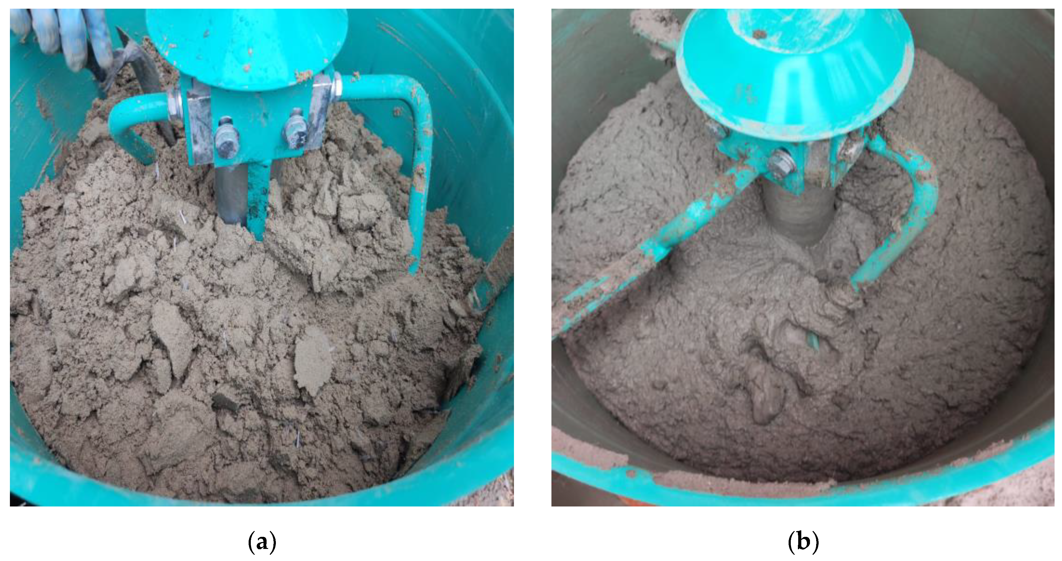
Natural quartz sand 0-1 mm, CEM II/A-S 52.5 R Portland slag cement in line with CP 012-1:2007 [37]; NE 013:2002 [38]; GP 075:2002 [39]; ATE 004-07/1707-2022 [40] and limestone filler from a local quarry basin were used as main components for the preparation of the cementitious mortars. All mixtures were reinforced with 12 mm long monofilament polypropylene fibers with the equivalent diameter of 21-34 microns. The tensile strength of the fibers, according to the manufacturer is ≥ 300 N/mm2 [41]. Two types of additives were used in every mixture, a viscosity modifying agent consisting in an aqueous solution of a high-molecular weight synthetic copolymer and a superplasticizer that enables fast strength development at early ages of hydration at low ambient and heat curing temperatures [42]. The M28 mix appearance and texture before and after the addition of the additive and final mixing are illustrated in Figure 3.
3. Extrudability
Based on the material system and the feeder configuration, there are four types of 3D printers (Figure 4), [43,44,45,46,47,48,49]. In order to supply the mixed mortar to the nozzle two types of feeders may be utilized: remote and local (Figure 4a, b, d). The remote feeder stores the 3D material and sends it to the printing nozzle or the local material bin via a transmitting pipe (Figure 4a, b). On the other hand, the raw extruding systems do not require a material feeder since the extruding mechanism serves as the material bin, as illustrated in Figure 4c.
For the printing of the fiber reinforced mortars described in this work a system composed of a material remote feeder, screw pump, hose and nozzle was utilized (Figure 4a). Even though no extruding mechanism was used, in Table 2 the first analyzing parameter is termed ”extrudability”. The latter is described as the process of deposition of continuous layers of mixture through a nozzle, according to a specific path. The term refers to a printing property being used for the characterization of both configurations (with and without extruding mechanism).
The extrudability issues cannot be adjusted during the printing process. The changes made to a mixture can be quantified only by referring to a looped process between before and after the addition or substitution of components. As a general rule, the mixtures with less stiffness are preferable for a smooth extrusion process (Figure 5). On the other hand, a too viscose mixture causes clogging during printing, like in the case of mixes M1-M16.
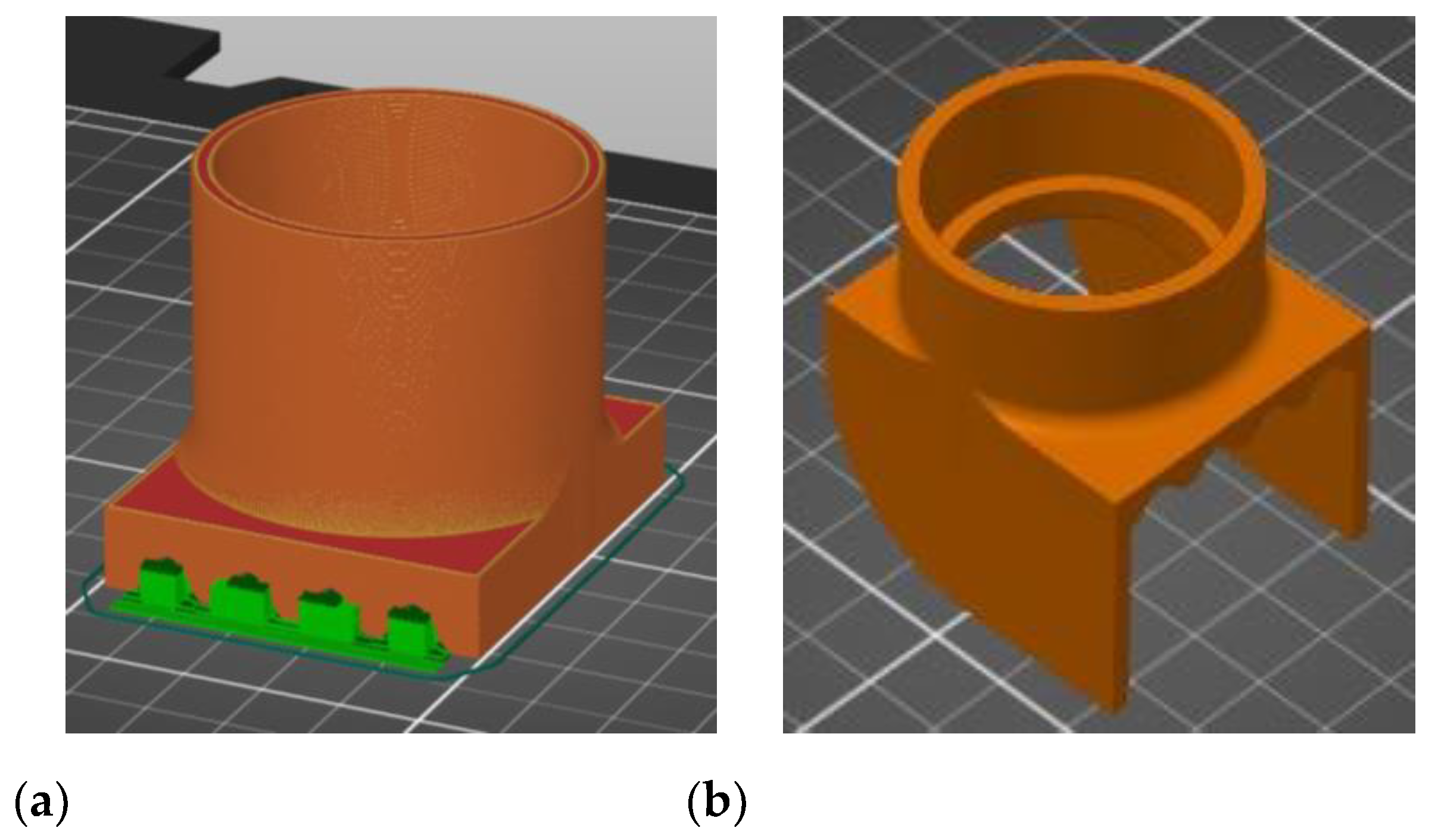
In addition to the mixture viscosity, extrudability is also influenced by the cross-section shape and size of the nozzle, as well as the frictional adhesion stress between the printing material and the rotor, stator and nozzle. In this respect, the rotor and the stator were sprayed with a silicone oil product to enable a lubricated engagement of the gears. As for the nozzles, all the configurations (18-, 20-, 25- and 45-mm) were designed and printed specifically for this work using a commercially available 3D printer loaded with a recycled Polylactic acid (PLA) filament (Figure 6), [50,51]. It was found that only the M27 mix was blocked at the nozzle level (for the diameters of 18-, 20- and 25- mm), the rest of the mixtures exhibited clogging in the pump feeder shaft or in the outlet unit. Two end accessories were designed and manufactured for the nozzles, one that ensures a waved surface between the layers (to increase the layer bonding), (Figure 7a) and one that ensures smooth lateral surfaces for the printed elements (Figure 7b). While the utilization of the second end cap accessory is a matter of choice regarding the finishing texture of the printed element, the utilization of the first one does not significantly improve the overal behavior or the aspect of the printed elements.
Figure 6.
Nozzles: (a) 3D model, (b) printer monitor and control, (c) end products.
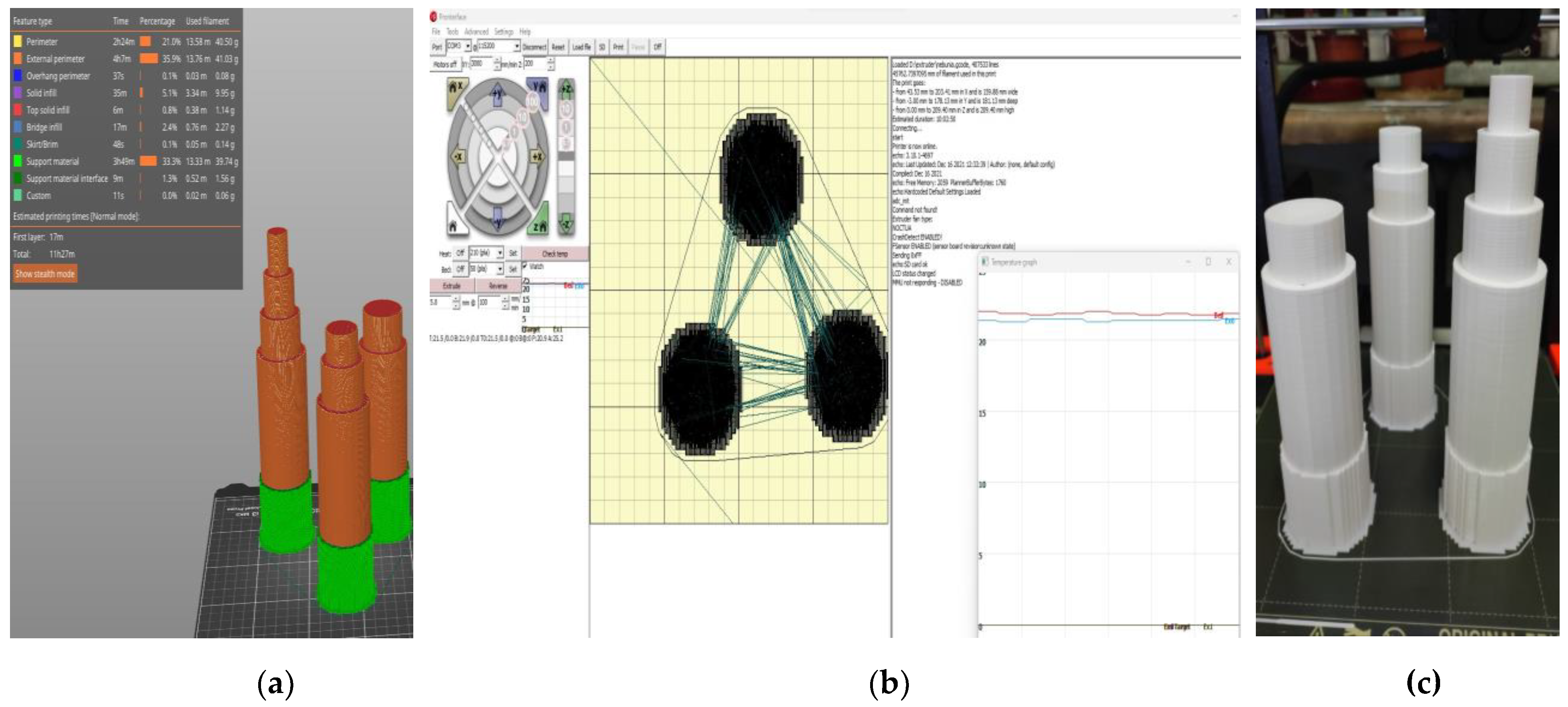
Figure 7.
End accessories for the nozzles: (a) end cap that ensures a waved surface between the layers, (b) end cap that ensures smooth lateral surfaces for the printed elements.
Figure 7.
End accessories for the nozzles: (a) end cap that ensures a waved surface between the layers, (b) end cap that ensures smooth lateral surfaces for the printed elements.
The extrudability is also influenced by the separation of the materials in the hose due to insufficient mixing before the pumping stage is initiated. The mixing methods presented in Table 1 were developed by testing other 30 mixtures that had been prepared by varying the order in which components were added and the mixing speed and time. Since these mixtures were used only for the finetuning of the preparation methods, they are not presented and discussed in the following parts of this paper.
For all the mixtures, it was found that pausing the printing process brings visible changes in materials rheological properties and causes insufficient bonding of the layers due to the lack of surface moisture.
4. Buildability
Buildability is considered to be the paramount parameter for a printable mixture. By definition, a printed material with satisfactory buildability should hold its shape without excessive deformations and should have acceptable settlement at the bottom layers [52]. In order to develop such a material, all the mixtures indicated in Table 2 were slowly pumped through the system so as to visually observe which one has sufficient stiffness and fast green strength gaining to maintain a plane substrate for the upcoming layers. Figure 8 illustrates the difference between a mix (M10) with unsatisfactory buildability (local collapse by layer splitting) and a mix with high buildability (M26).
The buildability test is a common evaluation for the 3D printed materials which allows to determine the maximum number of layers that can be poured above each other without generating the collapse of the structure. For the mixtures with low or no buildability, the printed project collapsed either due to the progressive loss of stability (the bottom layers developed excessive deformation), (Figure 9a) or suddenly, by plastic failure (probably the ultimate stress in the lower third of the structure exceeded the material yield strength. On the other hand, for the mixes with high buildability, the test provided satisfactory results, independently of the nozzle dimension and end cap configuration (Figure 9b, c).
In order to increase the buildability of 3D printed mortars, the mixture can be supplemented with cement or silica powders. However, this solution was not selected for this work due to the fact that the mixture total cost would have significantly increased. On the other hand, the „fine tuning” of the mixture, although more time consuming, may provide a cost-effective solution.
5. Flowability
Flowability is defined as the ability of a material to both flow and fill an available space under its own weight [53,54]. In 3D printing applications, flowability is considered crucial for achieving a consistent manufacturing process, since it contributes to the reduction of print defects and the prevention of blockages. Flowability is influenced by various factors, including the printing process parameters and the rheological properties of the 3D mortar. The latter refers to the viscosity and yield stress, parameters that characterize the flow behavior. Therefore, it is essential to control the flowability of the 3D printed mortar, to optimize the manufacturing process and to achieve high-quality printed objects/structures. In this respect, the slump and the slump flow test are two widely used methods to measure the flowability of 3D printed mortars.
The slump test is a simple and common method to determine the flowability of fresh 3D mortars. The test involves measuring the slump, which is the deformation of the concrete when it is placed in a cone-shaped mold (Figure 10).
The values listed in Table 2 were determined by performing tests in accordance with the European Standard EN 12350-2:2019 [55]. A frustum of a cone made of steel that measures 300 mm in height, and having a top diameter of 100 mm and a bottom diameter of 200 mm was used. The cone was placed on a non-porous steel base plate before the tests were conducted. After that, the cone was half filled with fresh 3D mortar and tamped with 20 strokes of a tamping rod. After that, more material was added to fill the mold and the excess material was removed by performing a sawing motion with a trowel. The cone was then slowly and carefully lifted in a vertical direction, allowing the 3D mortar to flow freely and deform under its own weight. The slump was determined as the difference in height between the original height of the cone and the height of the 3D mortar after deformation (Figure 11). According to previous studies, the mixtures were fine-tuned to obtain values ranging from 40 to 60 mm [56].
The slump test has some limitations, which are particularly related to 3D printed mortars. The test does not account for the shear-thinning behavior of the mortar, which can result in inaccurate measurements [57]. Shear-thinning is a phenomenon in which the viscosity of a material decreases with increasing shear rate or deformation. This behavior is common to 3D printed mortars due to the high shear rates experienced during the printing process. Therefore, the slump test may not accurately represent the flowability of 3D printed mortars under printing conditions. In this respect, the slump flow test is more suitable for characterizing the flowability of 3D mortars since it may account for the shear-thinning behavior [55]. This test set-up is similar to the slump test, but in this case, after the mold is removed, the flow table is dropped 25 times. The distance that the 3D mortar spreads was measured using a measuring tape (Figure 12). This measurement is known as the slump flow, which is the average diameter of the concrete spread. The values were corelated to the ones already imposed for the slump test thus, resulting a slump flow range between 140 and 160 mm. These values were indicated in previous studies as suitable for 3D printed mixtures [56].
6. Flexural strength
Mechanical strength tests were performed on 3D printed specimens made with the mixtures that proved satisfactory properties in the fresh state. The specimens have either been extracted from blocks (case of the elements printed with the 20-mm nozzle) or directly printed into the desired shape (case of the elements manufactured using the 45-mm nozzle) based on the type of test to be conducted. The three-point bending tests were conducted on prism specimens at 24 hours, 7, 14 and 28 days following the standard [58]. For each specific time interval, 5 specimens manufactured with M28 mix and printed with the 10 mm nozzle and 5 specimens manufactured with the M27 mix and printed with the 45 mm nozzle were tested (Figure 13 and Figure 14). The load rate was maintained at 0.1 kN/s during the test. The data were automatically recorded by a data logger and transferred to a computer.
7. Compressive strength
The compressive tests were conducted on cubic specimens at 24 hours, 7, 14 and 28 days following the standard [59]. For each specific time interval, 10 specimens manufactured with M28 mix and printed with the 10 mm nozzle and 5 specimens manufactured with the M27 mix and printed with the 45 mm nozzle were tested (Figure 19 and Figure 20). The load rate was maintained at 0.5 kN/s during the test. The data were automatically recorded by a data logger and transferred to a computer.
It should be noted that the surface quality might contribute to the mechanical performance, as mentioned in [57]. However, in this study, all the surfaces of specimens were carefully polished and flattened before testing. Thus, the effect of the surface irregularities may be ignored. The variations of the compressive strengths at specific time intervals (24 hours, 7, 14 and 28 days) are illustrated in Figure 21, Figure 22, Figure 23 and Figure 24.
7. Discussion
Based on the results presented in Table 2 (extrudability, buildability, and flowability), it was found that the M27 and M28 mixes possessed the most favorable properties for 3D printing. Consequently, mortar specimens were prepared and tested for compressive and three-point bending strengths (Figure 25) using two nozzle dimensions (20 and 45 mm).
Results indicated that the M27 mix printed with a 20mm nozzle had significantly higher values compared to the M28 mix printed with a 45mm nozzle. Moreover, the specimens made with the 45mm nozzle showed a higher susceptibility to eccentricities, leading to significantly lower compressive and flexural strength values compared to the specimens printed with a 20mm nozzle. Also, the compressive failure mechanism of specimens made with M27 mix and printed with a 20mm nozzle was similar to the classic characteristic failure mode of cubic concrete specimens. Overall, the specimens made with M28 mix and printed with the 20 mm nozzle have a flexural strength advantage of approximately 53%, 50%, 36%, and 32% over the specimens made with M27 mix and printed with the 45 mm nozzle at 24 hours, 7 days, 14 days, and 28 days, respectively (Figure 25). On the other hand, the differences recorded for the compressive strengths are even higher. Thus, the specimens made with M28 mix and printed with the 20 mm nozzle have a compressive strength advantage of approximately 145%, 134%, 31%, and 60% over the specimens made with M27 mix and printed with the 45 mm nozzle at 24 hours, 7 days, 14 days, and 28 days, respectively (Figure 25). These findings suggest that the M27 mix with a 20mm nozzle is a better combination for 3D printing applications, as it provides remarkable properties in fresh state and higher compressive and flexural strengths which indicate a better structural stability compared to the specimens made with the M28 mix.
8. Conclusion and future research directions
This paper presents the development of a fiber-reinforced mortar that can be 3D printed without extrusion. The study involved the preparation of 30 mixtures using three distinct preparation methods, and other 28 mixtures after characterizing the preparation methods. The results presented in Table 2 showed that the M27 and M28 mixes have the most favorable fresh properties for 3D printing. The mechanical performance tests indicated that the 3D printed specimens made with the M28 mix and printed through the 20 mm nozzle have considerably higher strengths than the ones made with the M27 mix. Despite the success in developing the M28 mixtures for 3D printing, the study identified some challenges that need further consideration in future research. To address these challenges, the authors plan to print a prototype-scale structure using the M28 mix and the 20 mm nozzle. The prototype will be tested in dynamic/seismic mode, and reinforcing methods will be designed based on the authors' previously developed studies related to fiber-reinforced polymer materials and textile-reinforced mortars (Figure 26), [60,61,62,63,64,65,66].
Overall, this study presents a promising approach to 3D printing fiber-reinforced mortar without extrusion, and the results highlight the potential of using this technology for constructing complex structures with high strength and durability. The future research on this topic could lead to significant advances in the field of construction and infrastructure development. Also, the reduced facility requirements in this approach allow 3D-printing to be more available for civil engineering applications.
Author Contributions
Conceptualization, D.U. and Ș.V.Z.; methodology, D.U. and D.N.I.; validation, N.Ț., C.O. and I.A.S.; formal analysis, D.U. and R.A.P.; investigation, D.U.; resources, Ș.V.Z.; data curation, N.Ț. and C.O.; writing—original draft preparation, D.U.; writing—review and editing, N.Ț. and D.N.I.; visualization, D.U. and I.A.S.; supervision, D.U.; project administration, C.O.; funding acquisition, Ș.V.Z. All authors have read and agreed to the published version of the manuscript.
Funding
This paper was realized with the support of COMPETE 2.0 project nr.27PFE/2021, financed by the Romanian Government, Minister of Research, Innovation and Digitalization.
Data Availability Statement
The data underlying this article will be shared on reasonable request from the corresponding author
Acknowledgments
The materials tested and characterized in this work were provided by Holcim Romania and Master Builders Solutions Romania. Holcim Romania supports and promote the research activities on 3D printed constructions carried out by the Faculty of Construction and Building Services in Iasi.
Conflicts of Interest
The authors declare no conflict of interest.
References
- Alami, A.H.; Olabi, A.G.; Ayoub, M.; Aljaghoub, H.; Alasad, S.; Abdelkareem, M.A. 3D Concrete Printing: Recent Progress, Applications, Challenges, and Role in Achieving Sustainable Development Goals. Buildings 2023, 13, 924. [Google Scholar] [CrossRef]
- Jin, Y.; Gao, C. Hybrid Optimization of Green Supply Chain Network and Scheduling in Distributed 3D Printing Intelligent Factory. Sustainability 2023, 15, 5948. [Google Scholar] [CrossRef]
- Lam, E.H.Y.; Yu, F.; Zhu, S.; Wang, Z. 3D Bioprinting for Next-Generation Personalized Medicine. Int. J. Mol. Sci. 2023, 24, 6357. [Google Scholar] [CrossRef] [PubMed]
- Al-Tamimi, A.K.; Alqamish, H.H.; Khaldoune, A.; Alhaidary, H.; Shirvanimoghaddam, K. Framework of 3D Concrete Printing Potential and Challenges. Buildings 2023, 13, 827. [Google Scholar] [CrossRef]
- Fonseca, M.; Matos, A.M. 3D Construction Printing Standing for Sustainability and Circularity: Material-Level Opportunities. Materials 2023, 16, 2458. [Google Scholar] [CrossRef] [PubMed]
- Quah, T.K.N.; Tay, Y.W.D.; Lim, J.H.; Tan, M.J.; Wong, T.N.; Li, K.H.H. Concrete 3D Printing: Process Parameters for Process Control, Monitoring and Diagnosis in Automation and Construction. Mathematics 2023, 11, 1499. [Google Scholar] [CrossRef]
- Mendřický, R.; Keller, P. Analysis of Object Deformations Printed by Extrusion of Concrete Mixtures Using 3D Scanning. Buildings 2023, 13, 191. [Google Scholar] [CrossRef]
- Dams, B.; Chen, B.; Shepherd, P.; Ball, R.J. Development of Cementitious Mortars for Aerial Additive Manufacturing. Appl. Sci. 2023, 13, 641. [Google Scholar] [CrossRef]
- Bello, N.D.; Memari, A.M. Comparative Review of the Technology and Case Studies of 3D Concrete Printing of Buildings by Several Companies. Buildings 2023, 13, 106. [Google Scholar] [CrossRef]
- García-Alvarado, R.; Moroni-Orellana, G.; Banda, P. Development of Variable Residential Buildings with 3D-Printed Walls. Buildings 2022, 12, 1796. [Google Scholar] [CrossRef]
- Ibrahim, I.; Eltarabishi, F.; Abdalla, H.; Abdallah, M. 3D Printing in Sustainable Buildings: Systematic Review and Applications in the United Arab Emirates. Buildings 2022, 12, 1703. [Google Scholar] [CrossRef]
- Salandin, A.; Quintana-Gallardo, A.; Gómez-Lozano, V.; Guillén-Guillamón, I. The First 3D-Printed Building in Spain: A Study on Its Acoustic, Thermal and Environmental Performance. Sustainability 2022, 14, 13204. [Google Scholar] [CrossRef]
- Chen, M.; Li, L.; Zheng, Y.; Zhao, P.; Lu, L.; Cheng, X. Rheological and mechanical properties of admixtures modified 3D printing sulphoaluminate cementitious materials. Construction and Building Materials 2018, 189, 601–611. [Google Scholar] [CrossRef]
- Al-Noaimat, Y.A.; Ghaffar, S.H.; Chougan, M.; Al-Kheetan, M.J. A review of 3D printing low-carbon concrete with one-part geopolymer: Engineering, environmental and economic feasibility. Case Studies in Construction Materials 2023, 18, e01818. [Google Scholar] [CrossRef]
- Hou, S.; Xiao, J.; Duan, Z.; Ma, G. Fresh properties of 3D printed mortar with recycled powder. Construction and Building Materials 2021, 309, 125186. [Google Scholar] [CrossRef]
- Cao, X.; Yu, S.; Cui, H.; Li, Z. 3D Printing Devices and Reinforcing Techniques for Extruded Cement-Based Materials: A Review. Buildings 2022, 12, 453. [Google Scholar] [CrossRef]
- Asprone, D.; Auricchio, F.; Menna, C.; Mercuri, V. 3D printing of reinforced concrete elements: Technology and design approach. Constr. Build. Mater. 2018, 165, 218–231. [Google Scholar] [CrossRef]
- Katzer, J.; Szatkiewicz, T. Properties of concrete elements with 3-D printed formworks which substitute steel reinforcement. Constr. Build. Mater. 2019, 210, 157–161. [Google Scholar] [CrossRef]
- Salazar, B.; Aghdasi, P.; Williams, I.D.; Ostertag, C.P.; Taylor, H.K. Polymer lattice-reinforcement for enhancing ductility of concrete. Mater. Des. 2020, 196, 109184. [Google Scholar] [CrossRef]
- Xu, Y.; Šavija, B. Development of strain hardening cementitious composite (SHCC) reinforced with 3D printed polymeric reinforcement: Mechanical properties. Compos. Part B Eng. 2019, 174, 107011. [Google Scholar] [CrossRef]
- Volpe, S.; Sangiorgio, V.; Petrella, A.; Coppola, A.; Notarnicola, M.; Fiorito, F. Building Envelope Prefabricated with 3D Printing Technology. Sustainability 2021, 13, 8923. [Google Scholar] [CrossRef]
- Sanjayan, J.G.; Nematollahi, B.; Xia, M.; Marchment, T. Effect of surface moisture on inter-layer strength of 3D printed concrete. Constr. Build. Mater. 2018, 172, 468–475. [Google Scholar] [CrossRef]
- Van Der Putten, J.; Deprez, M.; Cnudde, V.; De Schutter, G.; Van Tittelboom, K. Microstructural Characterization of 3D Printed Cementitious Materials. Materials 2019, 12, 2993. [Google Scholar] [CrossRef] [PubMed]
- Van Der Putten, J.; De Schutter, G.; Van Tittelboom, K. Surface modification as a technique to improve inter-layer bonding strength in 3D printed cementitious materials. RILEM Tech. Lett. 2019, 4, 33–38. [Google Scholar] [CrossRef]
- Li, Z.; Wang, L.; Ma, G. Mechanical improvement of continuous steel microcable reinforced geopolymer composites for 3D printing subjected to different loading conditions. Compos. Part B Eng. 2020, 187, 107796. [Google Scholar] [CrossRef]
- Hambach, M.; Volkmer, D. Properties of 3D-printed fiber-reinforced Portland cement paste. Cem. Concr. Compos. 2017, 79, 62–70. [Google Scholar] [CrossRef]
- Ma, G.; Li, Z.; Wang, L.; Wang, F.; Sanjayan, J. Mechanical anisotropy of aligned fiber reinforced composite for extrusion-based 3D printing. Constr. Build. Mater. 2019, 202, 770–783. [Google Scholar] [CrossRef]
- Ogura, H.; Nerella, V.N.; Mechtcherine, V. Developing and Testing of Strain-Hardening Cement-Based Composites (SHCC) in the Context of 3D-Printing. Materials 2018, 11, 1375. [Google Scholar] [CrossRef]
- Farina, I.; Fabbrocino, F.; Carpentieri, G.; Modano, M.; Amendola, A.; Goodall, R.; Feo, L.; Fraternali, F. On the reinforcement of cement mortars through 3D printed polymeric and metallic fibers. Compos. Part B Eng. 2016, 90, 76–85. [Google Scholar] [CrossRef]
- Baz, B.; Aouad, G.; Leblond, P.; Al-Mansouri, O.; D’Hondt, M.; Remond, S. Mechanical assessment of concrete—Steel bonding in 3D printed elements. Constr. Build. Mater. 2020, 256, 119457. [Google Scholar] [CrossRef]
- Baz, B.; Aouad, G.; Remond, S. Effect of the printing method and mortar’s workability on pull-out strength of 3D printed elements. Constr. Build. Mater. 2019, 230, 117002. [Google Scholar] [CrossRef]
- Bester, F.; Heever, M.V.D.; Kruger, J.; Cho, S.; van Zijl, G. Steel Fiber Links in 3D Printed Concrete; Springer: Cham, The Netherlands, 2020; pp. 398–406. [Google Scholar]
- Wang, L.; Ma, G.; Liu, T.; Buswell, R.; Li, Z. Interlayer reinforcement of 3D printed concrete by the in-process deposition of U-nails. Cem. Concr. Res. 2021, 148, 106535. [Google Scholar] [CrossRef]
- Liu, M.; Zhang, Q.; Tan, Z.; Wang, L.; Li, Z.; Ma, G. Investigation of steel wire mesh reinforcement method for 3D concreteprinting. Arch. Civ. Mech. Eng. 2021, 21, 34. [Google Scholar] [CrossRef]
- Matthäus, C.; Kofler, N.; Kränkel, T.; Weger, D.; Gehlen, C. Interlayer Reinforcement Combined with Fiber Reinforcement for Extruded Lightweight Mortar Elements. Materials 2020, 13, 4778. [Google Scholar] [CrossRef] [PubMed]
- Sun, X.; Gao, C.; Wang, H. Bond performance between BFRP bars and 3D printed concrete. Constr. Build. Mater. 2020, 269, 121325. [Google Scholar] [CrossRef]
- CP 012-1-2007 Cod pentru producerea betonului (in Romanian).
- NE 013 – 2002 Cod de practică pentru execuţia elementelor prefabricatelor din beton, beton armat şi beton precomprimat (in Romanian).
- GP 075:2002 Ghid pentru stabilirea criteriilor de performanță a compozițiilor pentru betoane armate dispers cu fibre metalice (in Romanian).
- ATE 004-07/1707-2022 Procedeu de execuție a îmbrăcăminților rutiere din beton de ciment (in Romanian).
- https://romfracht.com/ro/fibers/?gclid=Cj0KCQjwuLShBhC_ARIsAFod4fLouQv6ihOaNCAF9iAex2c8Y6g90XyG4GRtyNW6kr4-UBAN7HQFLjsaAgUgEALw_wcB (Accesed on 05.04.2023).
- https://www.master-builders-solutions.com/ro-ro/products (Accesed on 05.04.2023).
- Villacis, N.; Gualavisi, M.; Narvaez-Munoz, C.; Carrion, L.; Loza-Matovelle, D.; Naranjo, F. Additive manufacturing of a theological characterized cement-based composite material. In Proceedings of the 2017 European Conference on Electrical Engineering and Computer Science (EECS), Bern, Switzerland, 19 November 2017; pp. 326–331. [Google Scholar]
- Olivas, A.; Helsel, M.A.; Martys, N.; Ferraris, C.; George, W.L.; Ferron, R. Rheological Measurement of Suspensions Without Slippage: Experiment and Model; National Institute of Standards and Technology: Gaithersburg, MA, USA, 2016. [Google Scholar]
- Panda, B.; Singh, G.V.P.B.; Unluer, C.; Tan, M.-J. Synthesis and characterization of one-part geopolymers for extrusion based 3D concrete printing. J. Clean. Prod. 2019, 220, 610–619. [Google Scholar] [CrossRef]
- Nair, S.A.O.; Panda, S.; Santhanam, M.; Sant, G.; Neithalath, N. A critical examination of the influence of material characteristics and extruder geometry on 3D printing of cementitious binders. Cem. Concr. Compos. 2020, 112, 103671. [Google Scholar] [CrossRef]
- Lim, J.H.; Weng, Y.; Pham, Q.-C. 3D printing of curved concrete surfaces using Adaptable Membrane Formwork. Constr. Build. Mater. 2019, 232, 117075. [Google Scholar] [CrossRef]
- Xu, J.; Ding, L.; Cai, L.; Zhang, L.; Luo, H.; Qin, W. Volume-forming 3D concrete printing using a variable-size square nozzle. Autom. Constr. 2019, 104, 95–106. [Google Scholar] [CrossRef]
- Ma, G.; Li, Z.; Wang, L.; Wang, F.; Sanjayan, J. Mechanical anisotropy of aligned fiber reinforced composite for extrusion-based 3D printing. Constr. Build. Mater. 2019, 202, 770–783. [Google Scholar] [CrossRef]
- https://www.prusa3d.com/category/original-prusa-i3-mk3s/?gclid=Cj0KCQjwuLShBhC_ARIsAFod4fIvQM2FeRdV7ojyFYXp7TWApkmqjEaw99pJnRBwk-gt0BsYoD4QKl4aApexEALw_wcB (Accessed on 05.04.2023).
- https://www.pronterface.com/ (Accessed on 05.04.2023).
- Zhang, C.; Nerella, V.N.; Krishna, A.; Wang, S.; Zhang, Y.; Mechtcherine, V. Mix design concepts for 3D printable concrete: a review, Cem. Concr. Compos 2021, 122, 104155. [Google Scholar] [CrossRef]
- G. Ma, Z. Li, L. Wang, Printable properties of cementitious material containing copper tailings for extrusion based 3D printing, Constr. Build. Mater. 2018, 162, 613–627.
- G. Bai, L. Wang, G. Ma et al., 3D printing eco-friendly concrete containing under-utilized and waste solids as aggregates, Cement and Concrete Composites 2021, 1, 104037. [CrossRef]
- EN 12350-2:2019 - Testing fresh concrete - Part 2: Slump test.
- Tay, Y.W.D.; Qian, Y.; Tan, M.J. Printability region for 3D concrete printing using slump and slump flow test, Compos. B Eng. 2019, 174, 106968. [Google Scholar]
- Chen, Y.; Zhang, Y.; Pang, B.; Liu, Z.; Liu, G. Extrusion-based 3D printing concrete with coarse aggregate: Printability and direction-dependent mechanical performance. Construction and Building Materials 2021, 296, 123624. [Google Scholar] [CrossRef]
- SR EN 12390-5:2019 Încercare pe beton întărit. Partea 5: Rezistența la încovoiere a epruvetelor (in Romanian).
- SR EN 12390-3:2002 Încercare pe beton întărit. Partea 3: Rezistenţa la compresiune a epruvetelor.
- Ungureanu, D.; Taranu, N.; Isopescu, D.N.; Lupasteanu, V.; Scutaru, M.C.; Hudisteanu, I. Failure particularities of adhesively bonded joints between pultruded GFRP composite profiles. IOP Conference Series-Materials Science and Engineering 2018, 400, 032011. [Google Scholar] [CrossRef]
- Hudisteanu, I.; Taranu, N.; Isopescu, D.N.; Entuc, I.S.; Oprisan, G.; Ungureanu, D. Numerical analysis of intralaminar damage evolution on various composite laminates. IOP Conference Series-Materials Science and Engineering 2018, 400, 042031. [Google Scholar] [CrossRef]
- Ungureanu, D. ; Taranu, N; Ghiga, D. A.; Isopescu, D.N.; Mihai, P.; Cozmanciuc, R. Diagonal Tensile Test on Masonry Panels Strengthened with Textile-Reinforced Mortar Materials 2021, 14, 7021. [Google Scholar]
- Lupasteanu, V.; Ungureanu, D. ; Taranu, N; Isopescu, D. N.; Lupasteanu, R.; Mihai, P. Structural Response of Bonded Joints between FRP Composite Strips and Steel Plates Materials 2021, 14, 6722. [Google Scholar]
- Oprisan, G.; Taranu, N.; Munteanu, V.; Budescu, M.; Cozmanciuc, C.; Oltean, R. Improvement of concrete strength through confining with composite membranes. Romanian Journal of Materials 2011, 41, 302–315. [Google Scholar]
- Taranu, N.; Oprisan, G.; Entuc, I.; Budescu, M.; Munteanu, V.; Taranu, G. Composite and hybrid solutions for sustainable development in civil engineering. Environmental Engineering and Management Journal 2012, 11, 783–793. [Google Scholar] [CrossRef]
- Oprisan, G.; Taranu, N.; Budescu, M.; Entuc, I. Structural behaviour of reinforced concrete beams strengthened by CFRP plate bonding. Romanian Journal of Materials 2012, 42, 387–398. [Google Scholar]
Figure 1.
Configuration of the 3D gantry printer.
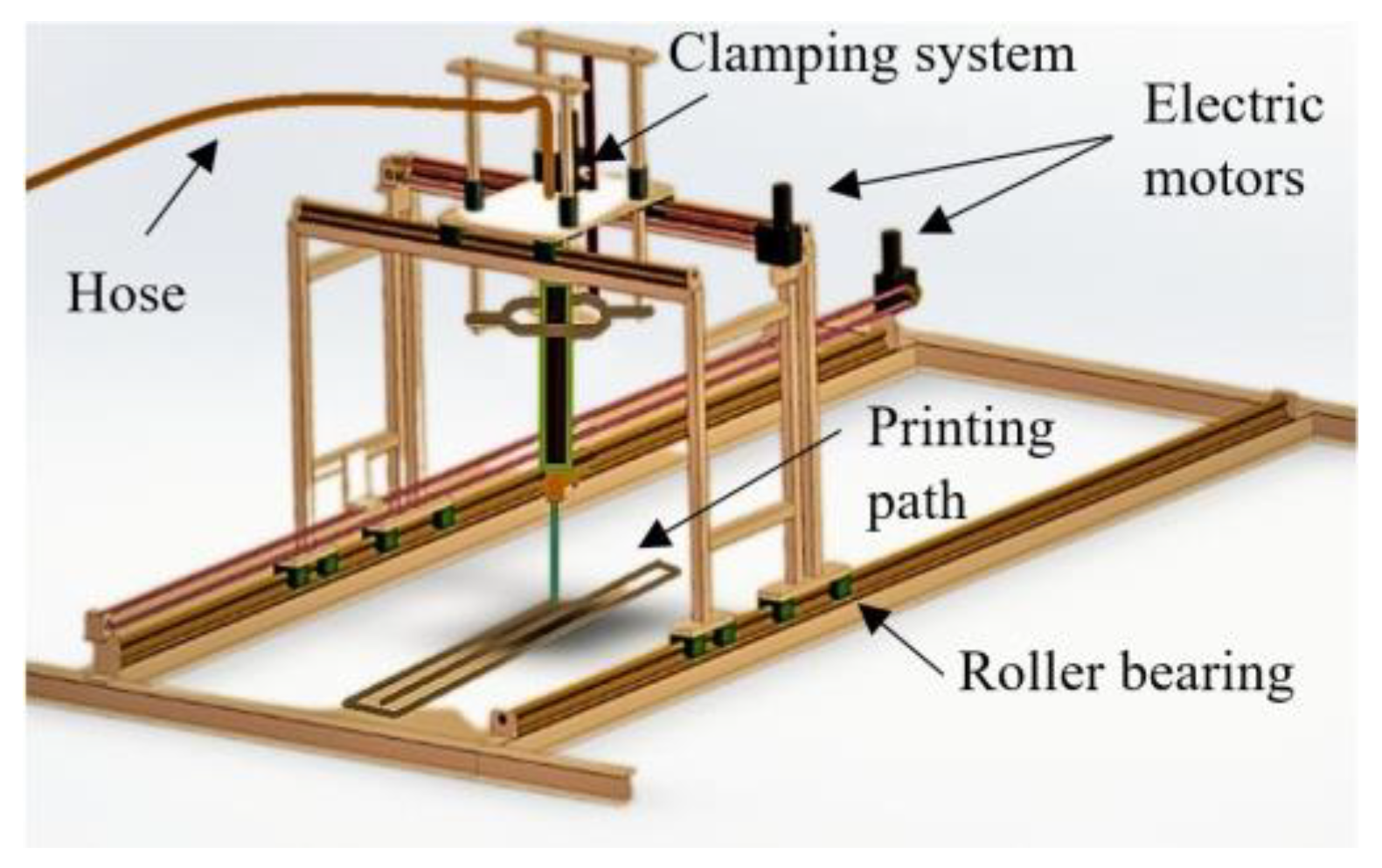
Figure 2.
Mortar pump configuration: 1 – container; 2 – outlet unit with inside screw pump; 3 – pressure gauge; 4 – connection for hose; 5 – rotor; 6 – stator; 7 – outlet unit.
Figure 2.
Mortar pump configuration: 1 – container; 2 – outlet unit with inside screw pump; 3 – pressure gauge; 4 – connection for hose; 5 – rotor; 6 – stator; 7 – outlet unit.
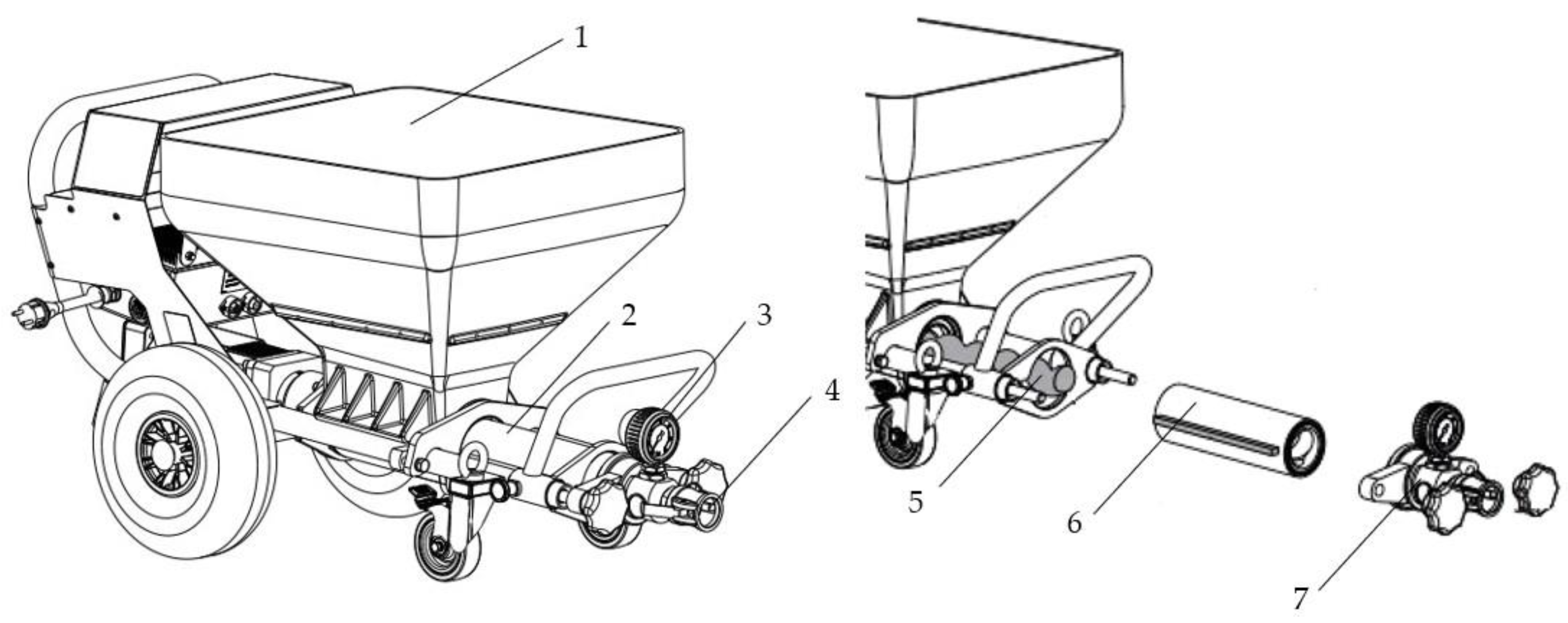
Figure 3.
M28 mix (20l charge) appearance and texture before (a) and after (b) the addition of the additives and final mixing.
Figure 3.
M28 mix (20l charge) appearance and texture before (a) and after (b) the addition of the additives and final mixing.
| Mix | Sand [kg] | Cement [kg] |
Limestone filler [kg] |
Fibers [kg] | Superplasticizer [%] |
Viscosity modifying agent [%] |
Water [l] |
W/C |
| M1 | 1358 | 580 | 200 | 7 | 1.2 | 0.2 | 200 | 0.345 |
| Extrudability | The M1 mix could not be extruded. Blockage occurred in the pump feeder shaft. | |||||||
| Mix | Sand [kg] | Cement [kg] |
Limestone filler [kg] |
Fibers [kg] | Superplasticizer [%] |
Viscosity modifying agent [%] |
Water [l] |
W/C |
| M2 | 1358 | 580 | 200 | 5 | 1.2 | 0.2 | 200 | 0.345 |
| Extrudability | The M2 mix could not be extruded. Blockage occurred in the pump feeder shaft. | |||||||
| Mix | Sand [kg] | Cement [kg] |
Limestone filler [kg] |
Fibers [kg] | Superplasticizer [%] |
Viscosity modifying agent [%] |
Water [l] |
W/C |
| M3 | 1358 | 580 | 200 | 3 | 1.2 | 0.2 | 200 | 0.345 |
| Extrudability | The M3 mix could not be extruded. Blockage occurred either in the pump feeder shaft or in the outlet unit. | |||||||
| Mix | Sand [kg] | Cement [kg] |
Limestone filler [kg] |
Fibers [kg] | Superplasticizer [%] |
Viscosity modifying agent [%] |
Water [l] |
W/C |
| M4 | 1358 | 580 | 200 | 1 | 1.2 | 0.2 | 200 | 0.345 |
| Extrudability | The M4 mix could be extruded but blockages still occurred. Thus, the water quantity was gradually increased starting from a step of 5 l/m3. The final quantity of water (265 l) corresponds to the M17 mix. | |||||||
| Mix | Sand [kg] | Cement [kg] |
Limestone filler [kg] |
Fibers [kg] | Superplasticizer [%] |
Viscosity modifying agent [%] |
Water [l] |
W/C |
| M17 | 1358 | 580 | 200 | 1 | 1.2 | 0.2 | 265 | 0.457 |
| Extrudability | The M17 mix could be extruded without blockages. | |||||||
| Buildability | The M17 mixture cannot be printed as large deformations occurred in the bottom layers. The mix is too fluid, the percentage of viscosity modifying agent was increased by 0.1 %. | |||||||
| Mix | Sand [kg] | Cement [kg] |
Limestone filler [kg] |
Fibers [kg] | Superplasticizer [%] |
Viscosity modifying agent [%] |
Water [l] |
W/C |
| M18 | 1358 | 580 | 200 | 1 | 1.2 | 0.3 | 265 | 0.457 |
| Extrudability | The M18 mix could be extruded without blockages. | |||||||
| Buildability | The M18 mixture cannot be printed as large deformations occurred in the bottom layers. The mix is too fluid, the percentage of viscosity modifying agent was increased by 0.1 %. | |||||||
| Table continued on the next page ↓ | ||||||||
| Mix | Sand [kg] | Cement [kg] |
Limestone filler [kg] |
Fibers [kg] | Superplasticizer [%] |
Viscosity modifying agent [%] |
Water [l] |
W/C |
| M19 | 1358 | 580 | 200 | 1 | 1.2 | 0.4 | 265 | 0.457 |
| Extrudability | The M19 mix could be extruded without blockages. | |||||||
| Buildability | The M19 mixture cannot be printed as large deformations still occurred in the bottom layers. The mix is too fluid, the percentage of viscosity modifying agent was increased by 0.2 %. | |||||||
| Slump flow | 150 mm | |||||||
| Mix | Sand [kg] | Cement [kg] |
Limestone filler [kg] |
Fibers [kg] | Plasticizer [%] |
Viscosity modifying agent [%] |
Water [l] |
W/C |
| M20 | 1358 | 580 | 200 | 1 | 1.2 | 0.6 | 265 | 0.457 |
| Extrudability | The M20 mix could be extruded without blockages. | |||||||
| Buildability | The M20 mixture cannot be printed as large deformations still occurred in the bottom layers. The mix is too fluid, the percentage of viscosity modifying agent was increased by 0.2 %. | |||||||
| Slump flow | 140 mm | |||||||
| Mix | Sand [kg] | Cement [kg] |
Limestone filler [kg] |
Fibers [kg] | Plasticizer [%] |
Viscosity modifying agent [%] |
Water [l] |
W/C |
| M21 | 1358 | 580 | 200 | 1 | 1.2 | 0.8 | 265 | 0.457 |
| Extrudability | The M21 mix could be extruded without blockages. | |||||||
| Buildability | The M21 mixture could be printed. | |||||||
| Slump flow | 110 mm | |||||||
| Printability | The open time of the M21 mix is too high. Thus, the quantity of water was gradually reduced by 5l/m3. The final quantity of water (245 l) corresponds to the M25 mix. Also, the percentage of plasticizer was increased by 0.2 %. | |||||||
| Mix | Sand [kg] | Cement [kg] |
Limestone filler [kg] |
Fibers [kg] | Plasticizer [%] |
Viscosity modifying agent [%] |
Water [l] |
W/C |
| M25 | 1358 | 580 | 200 | 1 | 1.4 | 0.8 | 245 | 0.422 |
| Extrudability | The M25 mix could not be extruded. Blockage occurred either in the pump feeder shaft or in the outlet unit. The quantity of water was gradually increased by 5l/m3. The final quantity of water (255 l) corresponds to the M27 mix. The plasticizer was reduced by 0.2 %. | |||||||
| Slump flow | 135 mm | |||||||
| Mix | Sand [kg] | Cement [kg] |
Limestone filler [kg] |
Fibers [kg] | Plasticizer [%] |
Viscosity modifying agent [%] |
Water [l] |
W/C |
| M27 | 1358 | 580 | 200 | 1 | 1.2 | 0.4 | 255 | 0.440 |
| Extrudability | The M27 mix could be extruded only through the 45 mm nozzle. | |||||||
| Buildability | The M27 mixture could be printed. | |||||||
| Printability | The open time of the M27 mix is around 35 minutes. | |||||||
| Table continued on the next page ↓ | ||||||||
| Mix | Sand [kg] | Cement [kg] | Limestone filler [kg] |
Fibers [kg] | Superplasticizer [%] | Viscosity modifying agent [%] |
Water [l] |
W/C |
| M28 | 1358 | 580 | 200 | 1 | 1.1 | 0.4 | 265 | 0.457 |
| Extrudability | The M28 mix could be extruded through the 18-, 20-, 25- and 45-mm nozzles. | |||||||
| Buildability | It was found that the M28 mix can build more than 100 layers without showing any type of failure. | |||||||
| Printability | The open time of the M28 mix is around 40 minutes. The optimum printing speed was limited to 100 mm/s to print layers with the same width as the nozzle smallest inlet (18 mm). | |||||||
| Slum flow | 160 mm | |||||||
| Slump | 40 mm | |||||||
| Density | 2249 kg/m3 | |||||||
Figure 4.
Material system and feeder configuration: (a) remote feeder, (b) remote and local feeder, (c) ram extruder, (d) local feeder.
Figure 4.
Material system and feeder configuration: (a) remote feeder, (b) remote and local feeder, (c) ram extruder, (d) local feeder.
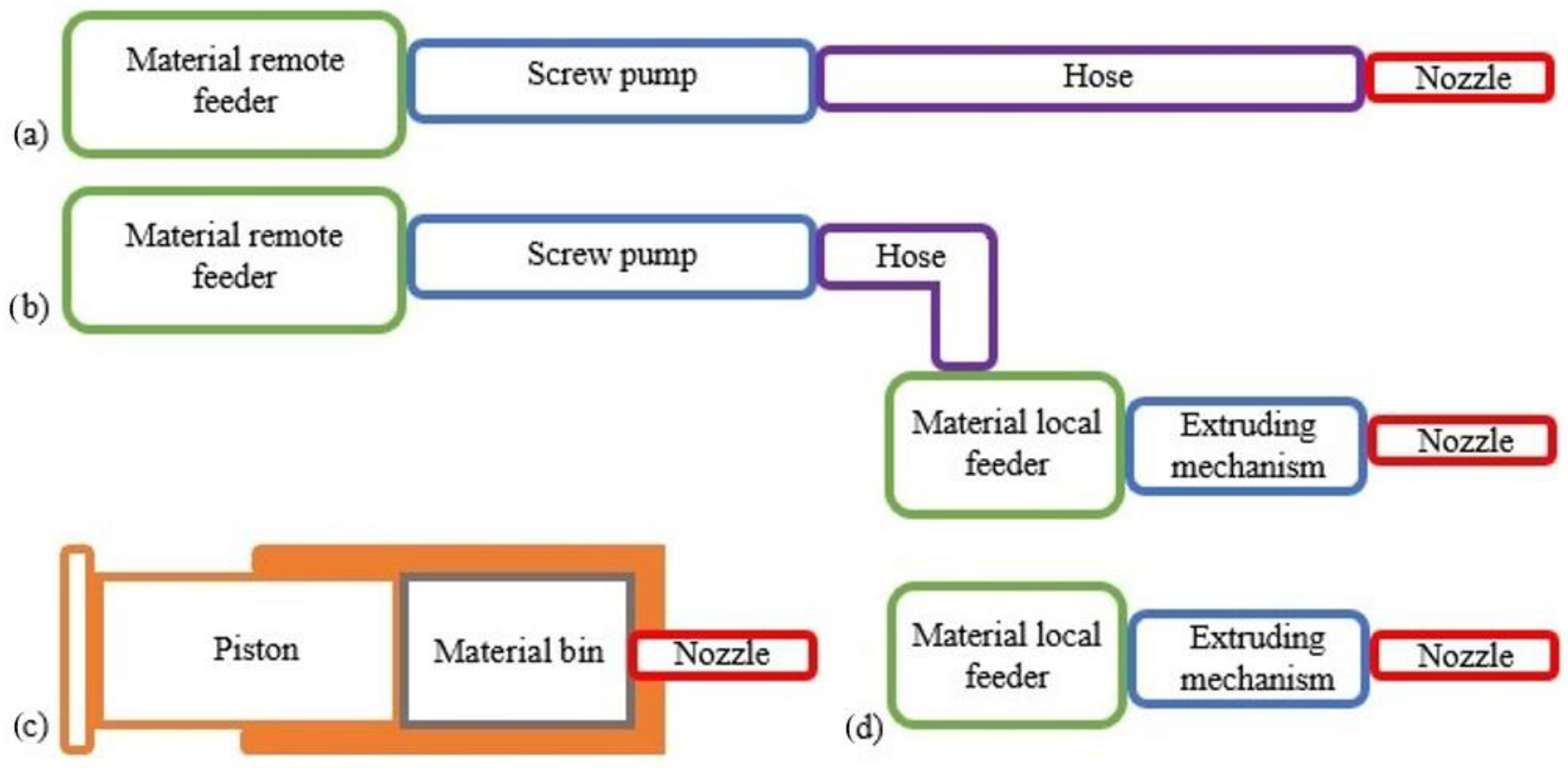
Figure 5.
Lateral view of printed elements: (a) M4 mix - difficult extrusion (clogging issues), (b) M28 mix - smooth extrusion. *For both specimens, the accessory depicted in Figure 7b was used.
Figure 5.
Lateral view of printed elements: (a) M4 mix - difficult extrusion (clogging issues), (b) M28 mix - smooth extrusion. *For both specimens, the accessory depicted in Figure 7b was used.
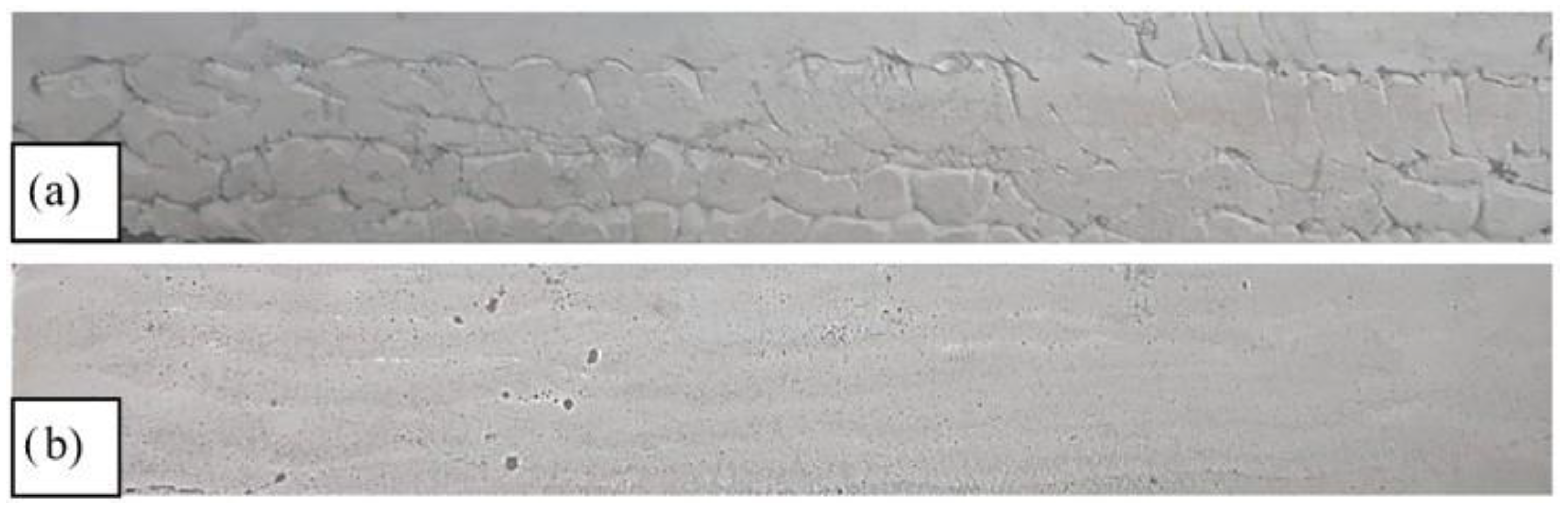
Figure 8.
3D layers: (a) collapsed layer by splitting (M10 mix), (b) layer with high buildability (M26 mix).
Figure 8.
3D layers: (a) collapsed layer by splitting (M10 mix), (b) layer with high buildability (M26 mix).
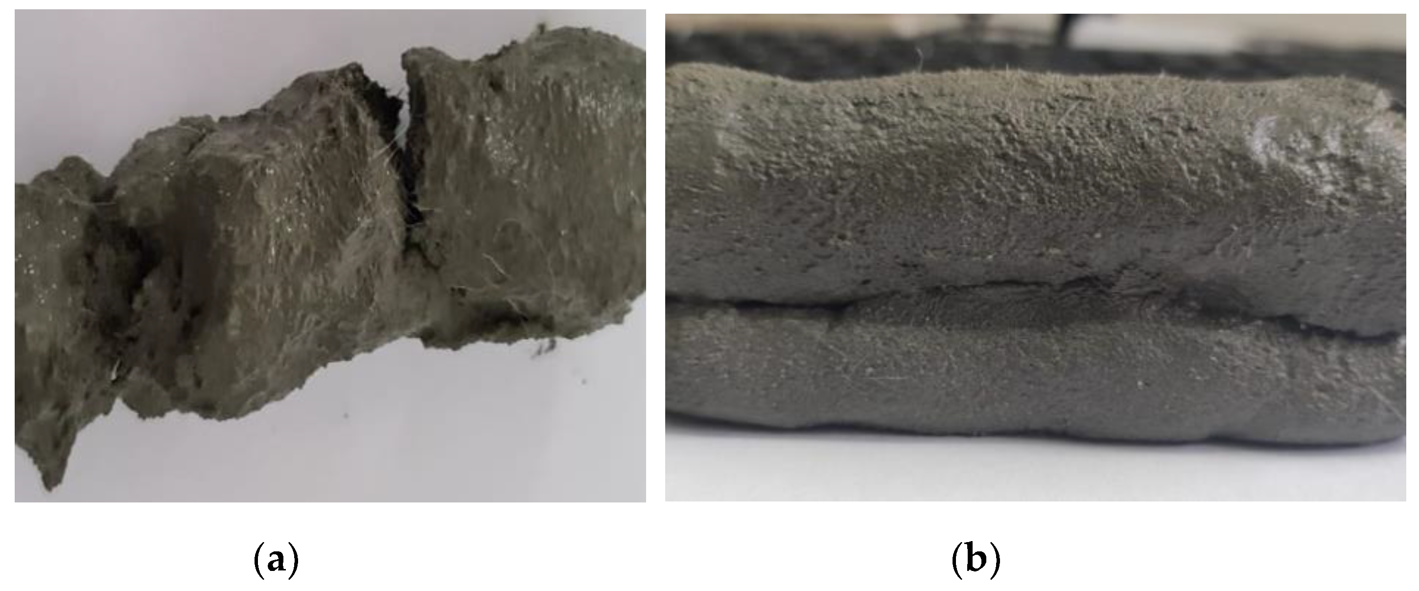
Figure 9.
The buildability test: (a) M20 mix – photo taken just before collapse (large deformations occurred in the lower 3 layers), (b) M28 mix, 45 mm nozzle – high buildability (over 100 layers), (c) M28 mix, 20 mm nozzle – high buildability (over 100 layers).
Figure 9.
The buildability test: (a) M20 mix – photo taken just before collapse (large deformations occurred in the lower 3 layers), (b) M28 mix, 45 mm nozzle – high buildability (over 100 layers), (c) M28 mix, 20 mm nozzle – high buildability (over 100 layers).
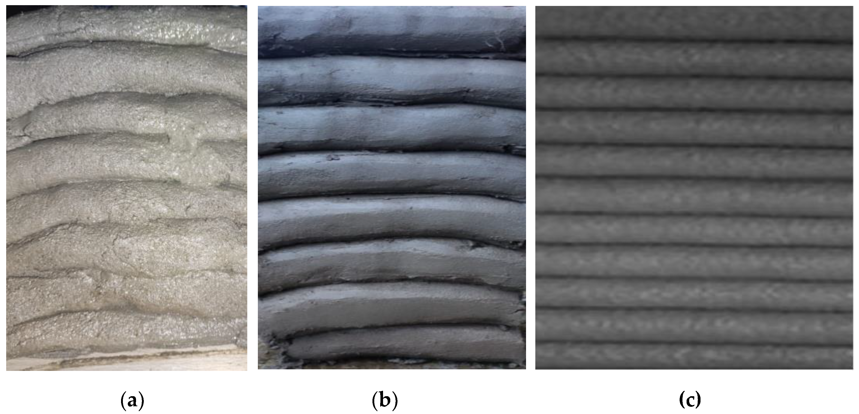
Figure 10.
Flow table and conical mold. Dimensions in mm.
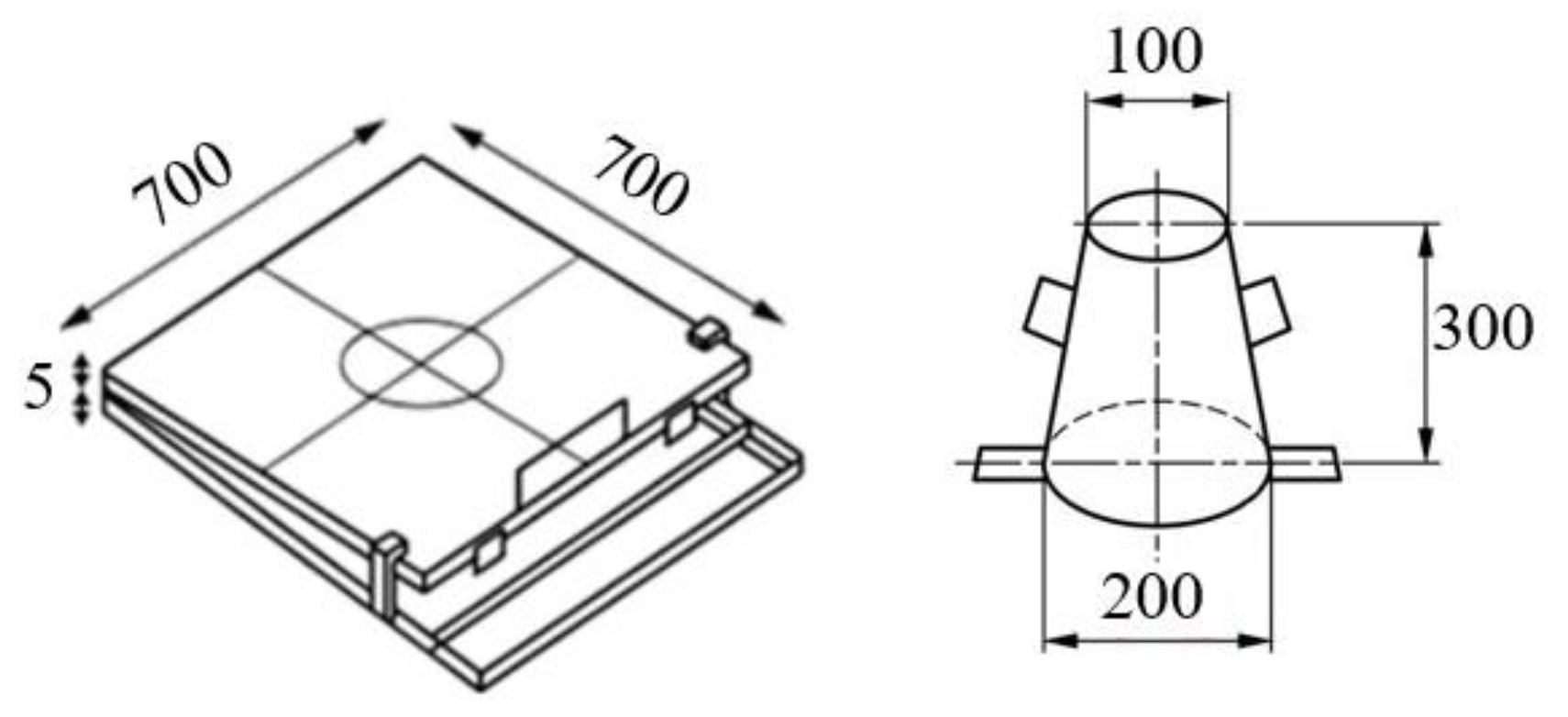
Figure 11.
Slump test of printable mixtures (a) M27 and (b) M28.
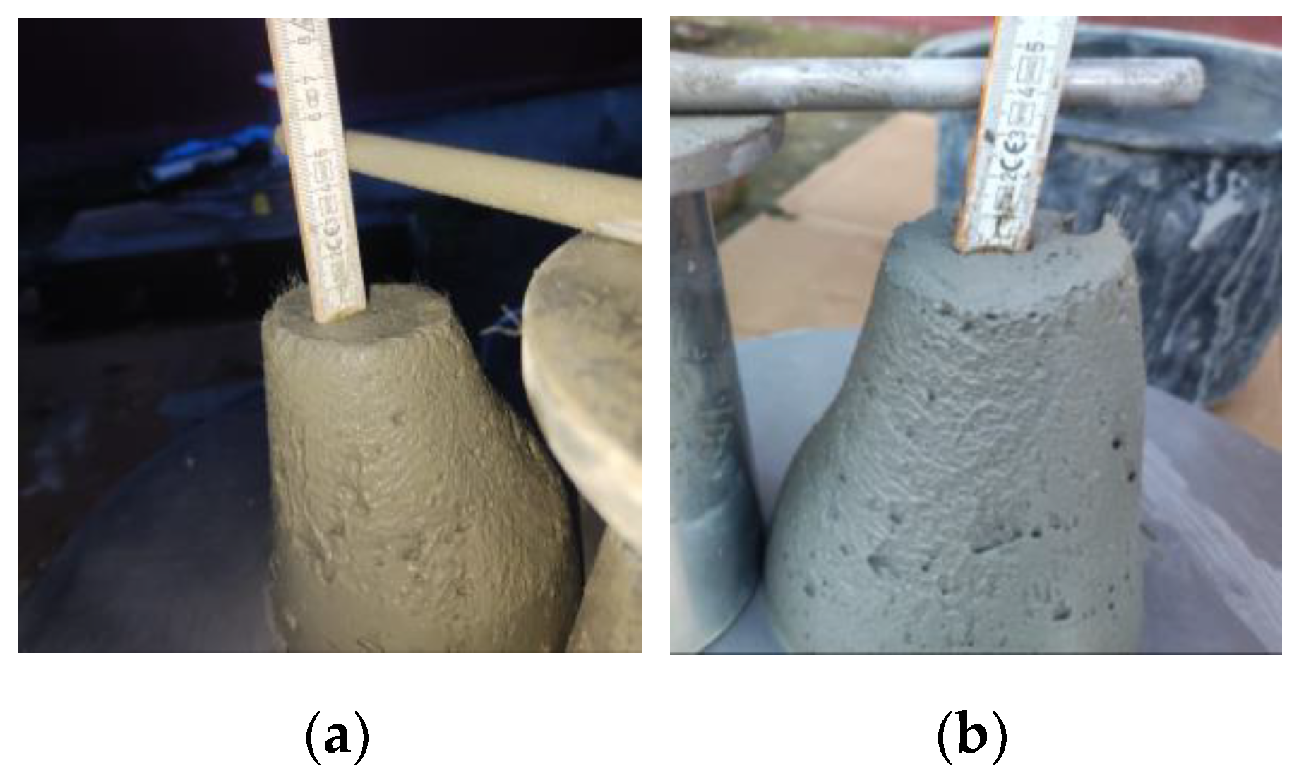
Figure 12.
Slump flow test: (a) M17 very fluid mix, (b) M20 fluid mix, (c) M28 fluid and printable mix.
Figure 12.
Slump flow test: (a) M17 very fluid mix, (b) M20 fluid mix, (c) M28 fluid and printable mix.
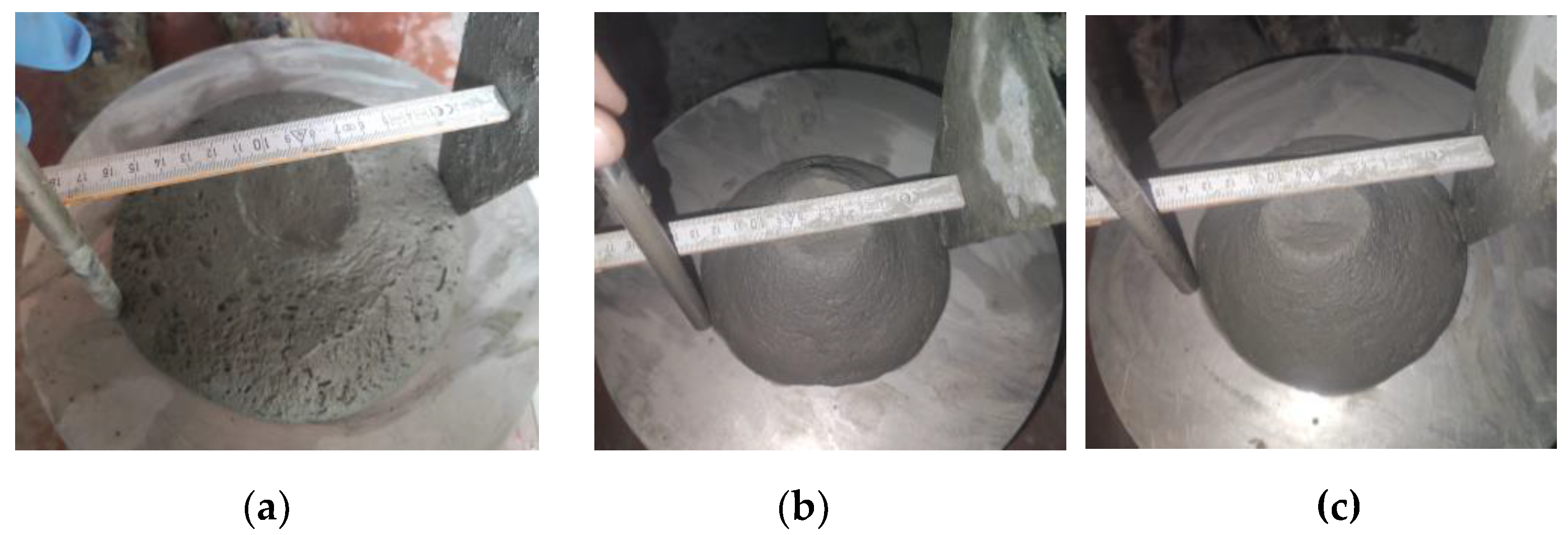
Figure 13.
Specimen manufactured with M27 mix and printed with the 45 mm nozzle: (a) Failure mode, (b) Sectional view and orientation of fibers.
Figure 13.
Specimen manufactured with M27 mix and printed with the 45 mm nozzle: (a) Failure mode, (b) Sectional view and orientation of fibers.
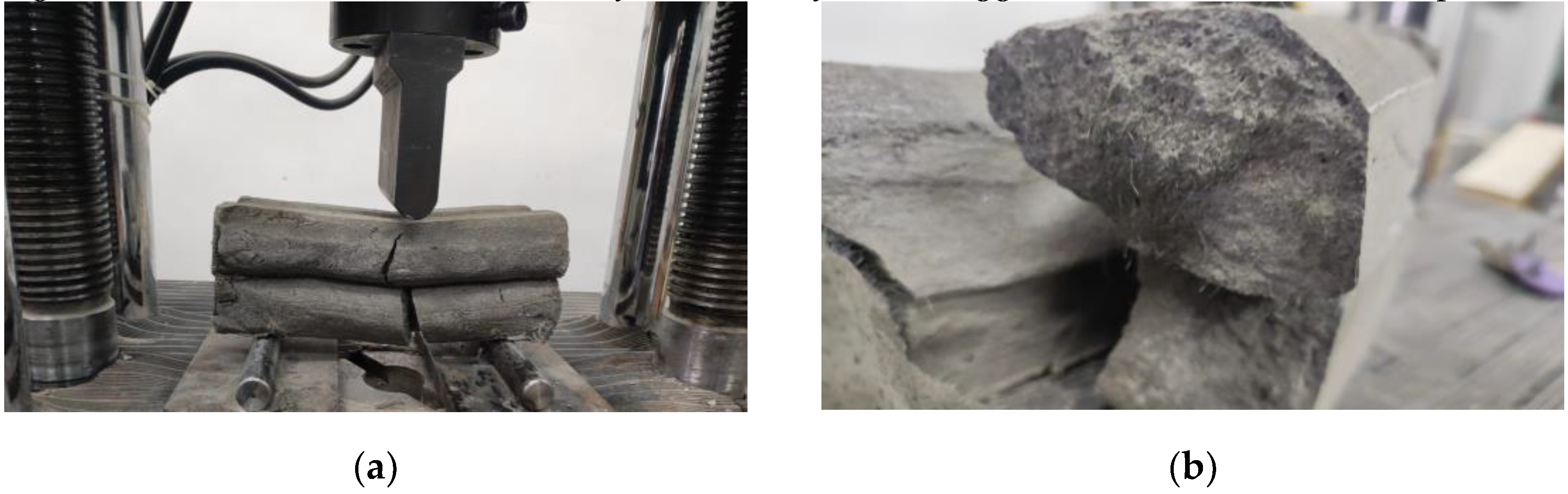
Figure 14.
Specimen manufactured with M28 mix and printed with the 20 mm nozzle: (a) Failure mode, (b) Orientation of fibers.
Figure 14.
Specimen manufactured with M28 mix and printed with the 20 mm nozzle: (a) Failure mode, (b) Orientation of fibers.
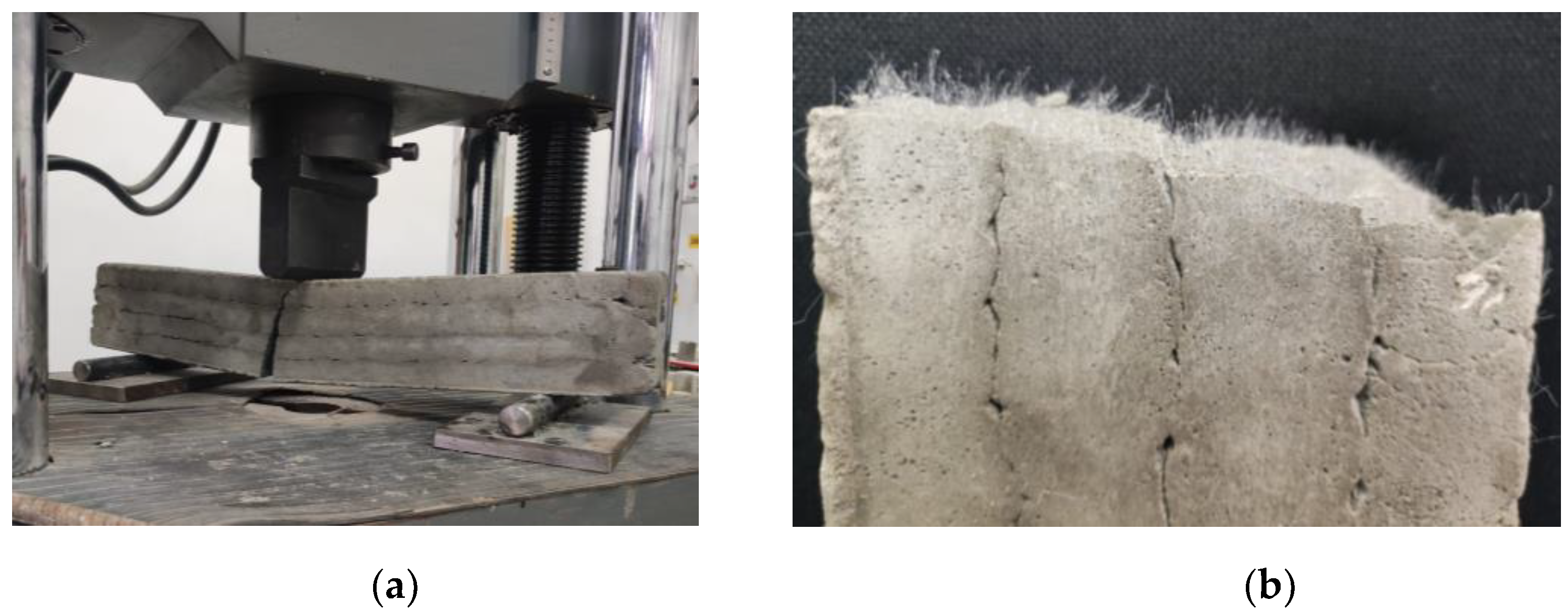
Figure 15.
Flexural strengths – 24 hours.
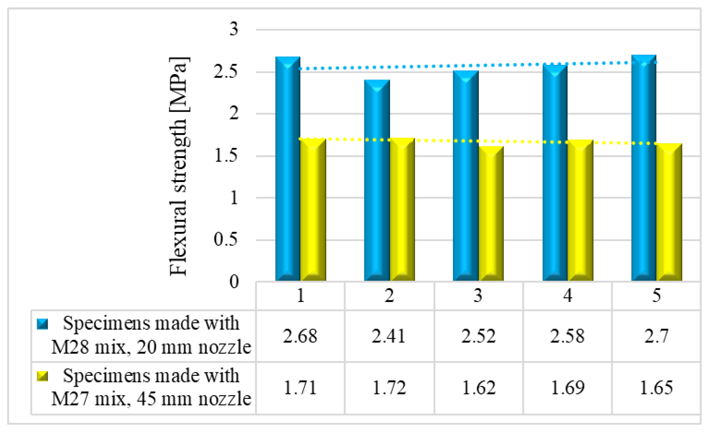
Figure 16.
Flexural strengths – 7 days.
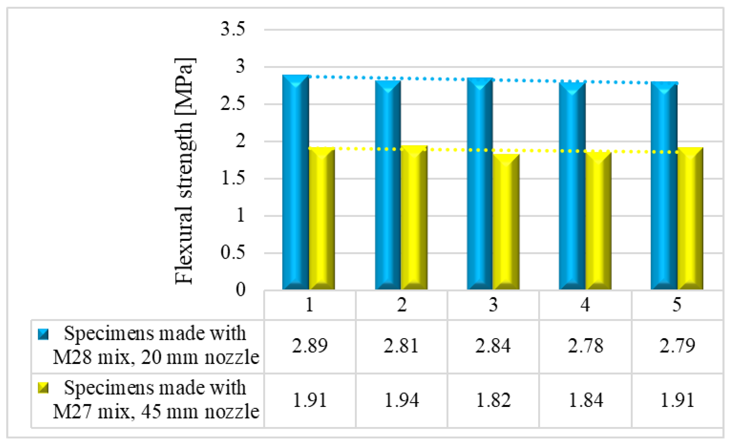
Figure 17.
Flexural strengths – 14 days.
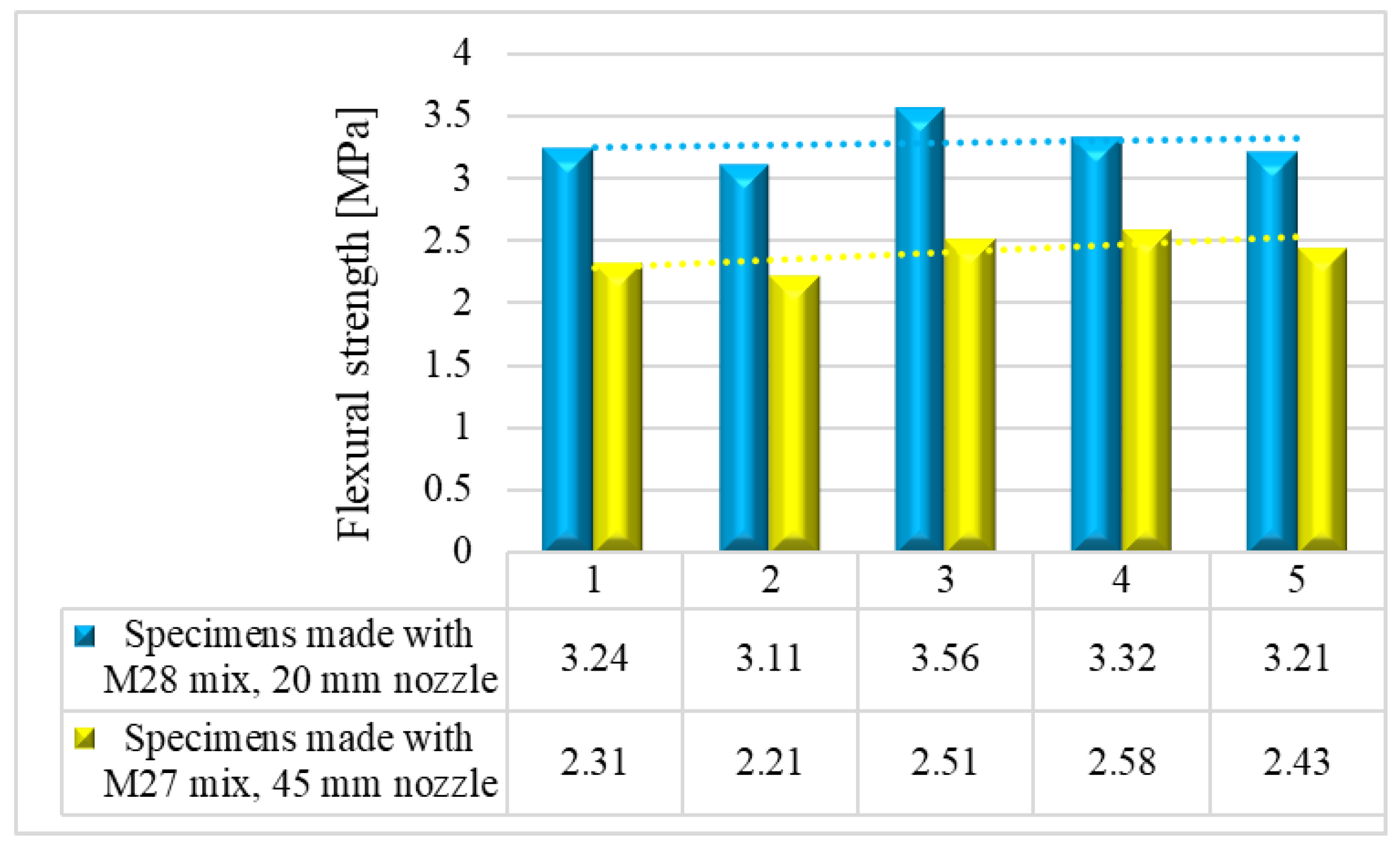
Figure 18.
Flexural strengths – 28 days.
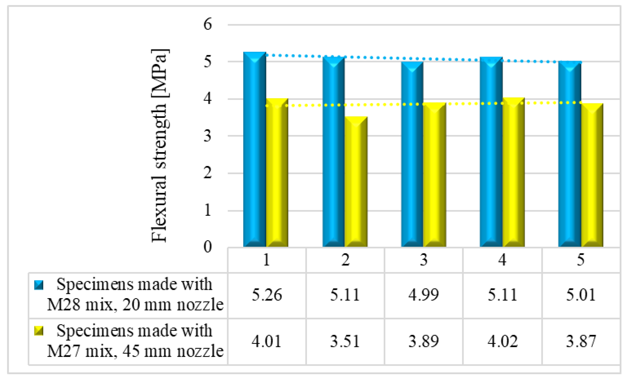
Figure 19.
Specimen manufactured with M28 mix and printed with the 20 mm nozzle: (a) Set-up, (b) Failure mode.
Figure 19.
Specimen manufactured with M28 mix and printed with the 20 mm nozzle: (a) Set-up, (b) Failure mode.
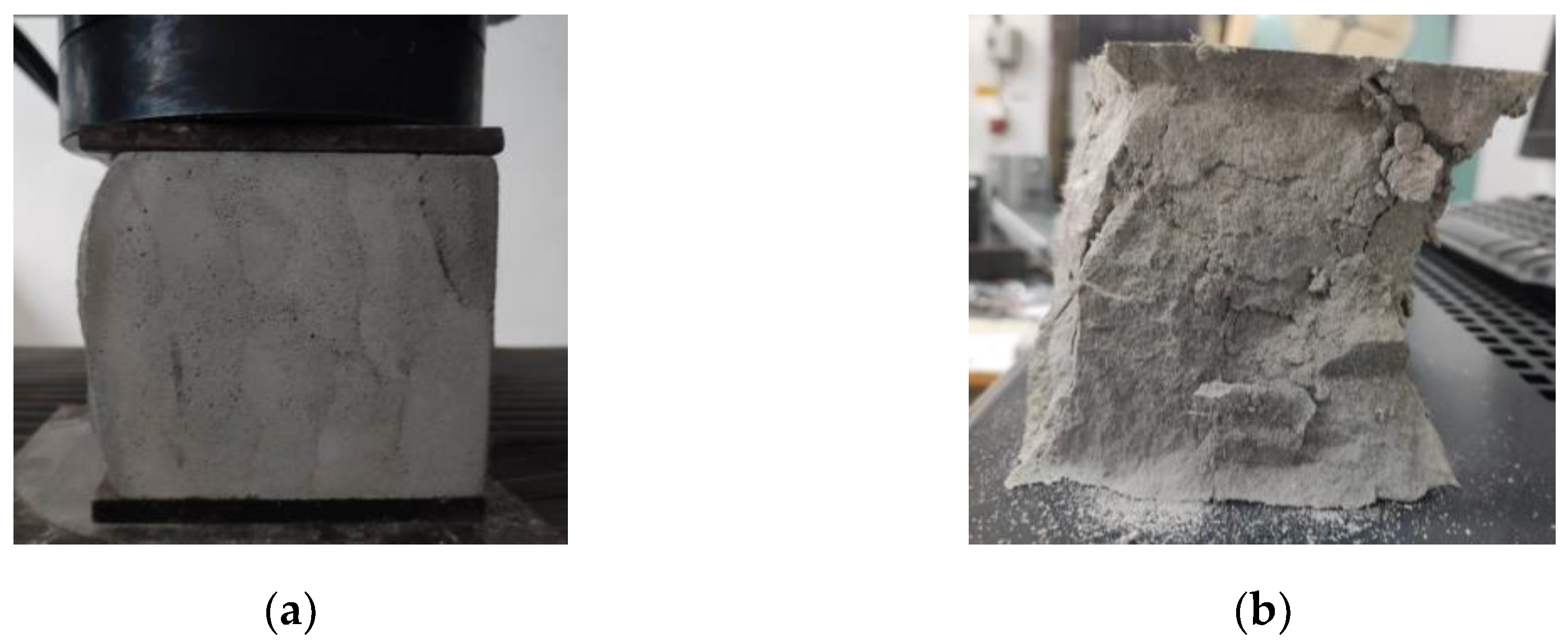
Figure 20.
Specimen manufactured with M27 mix and printed with the 45 mm nozzle: (a) Set-up, (b) Failure mode.
Figure 20.
Specimen manufactured with M27 mix and printed with the 45 mm nozzle: (a) Set-up, (b) Failure mode.
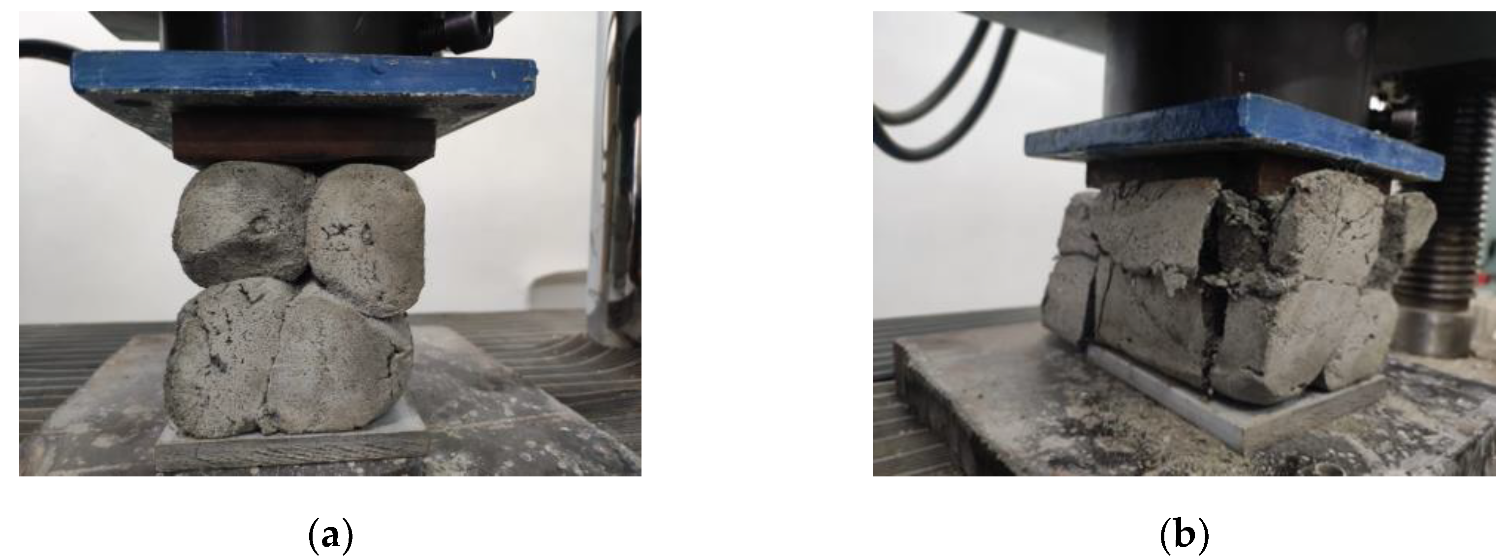
Figure 21.
Compressive strengths – 24 hours.
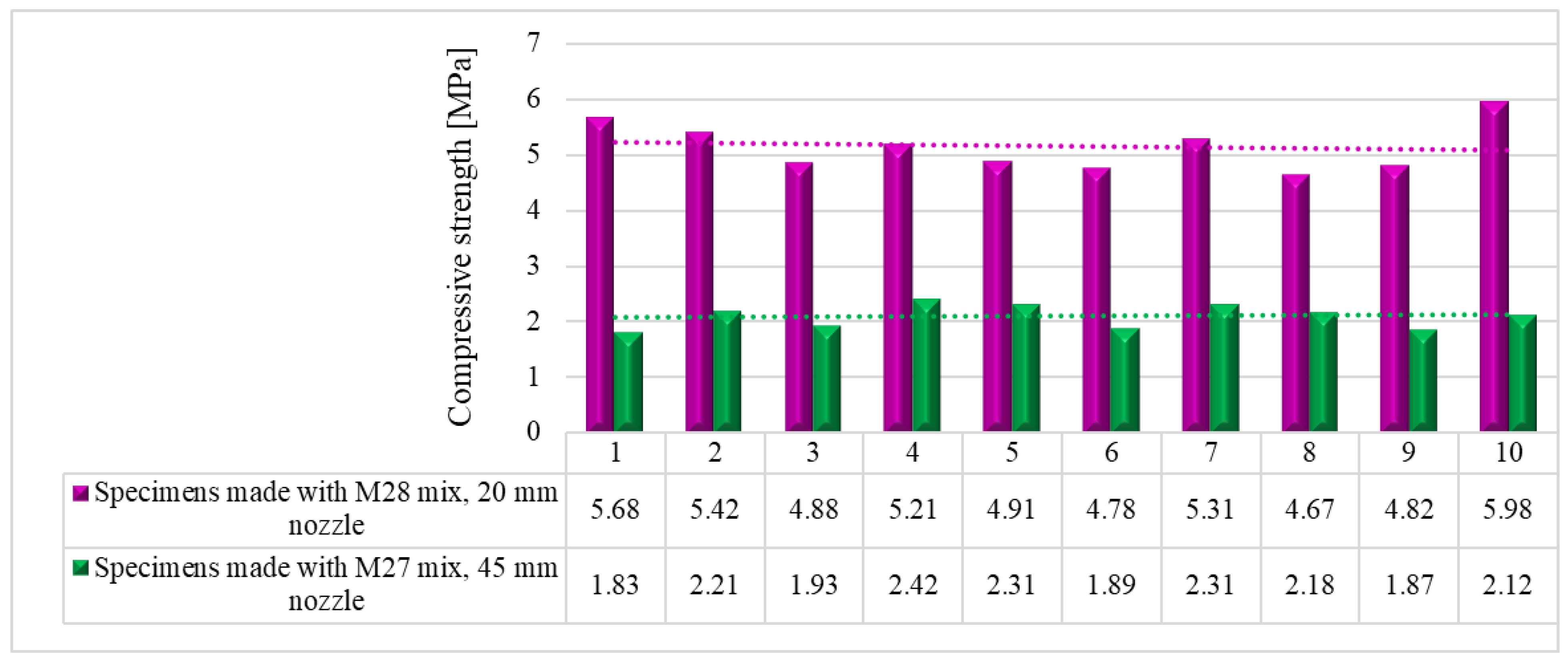
Figure 22.
Compressive strengths – 7 days.
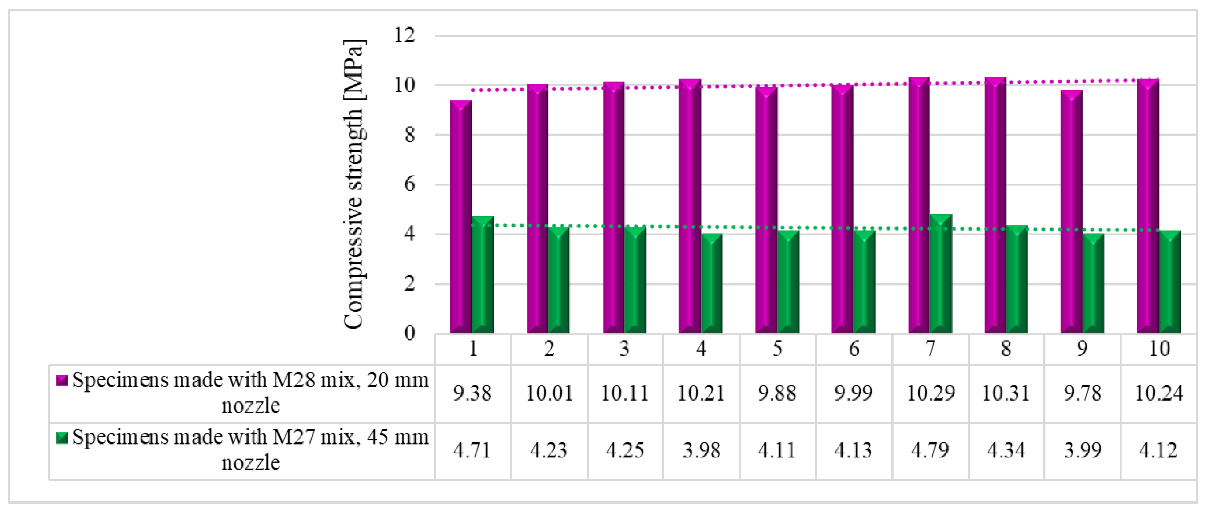
Figure 23.
Compressive strengths – 14 days.
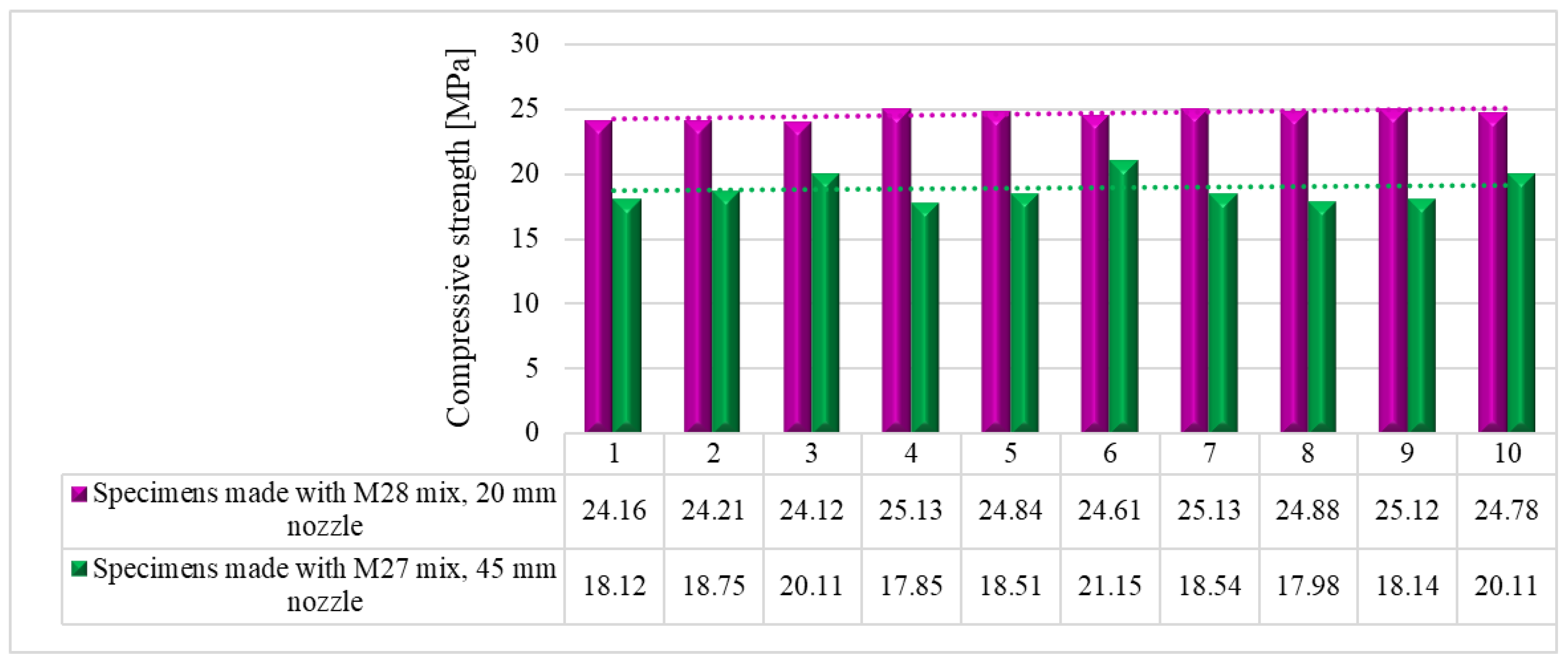
Figure 24.
Compressive strengths – 28 days.
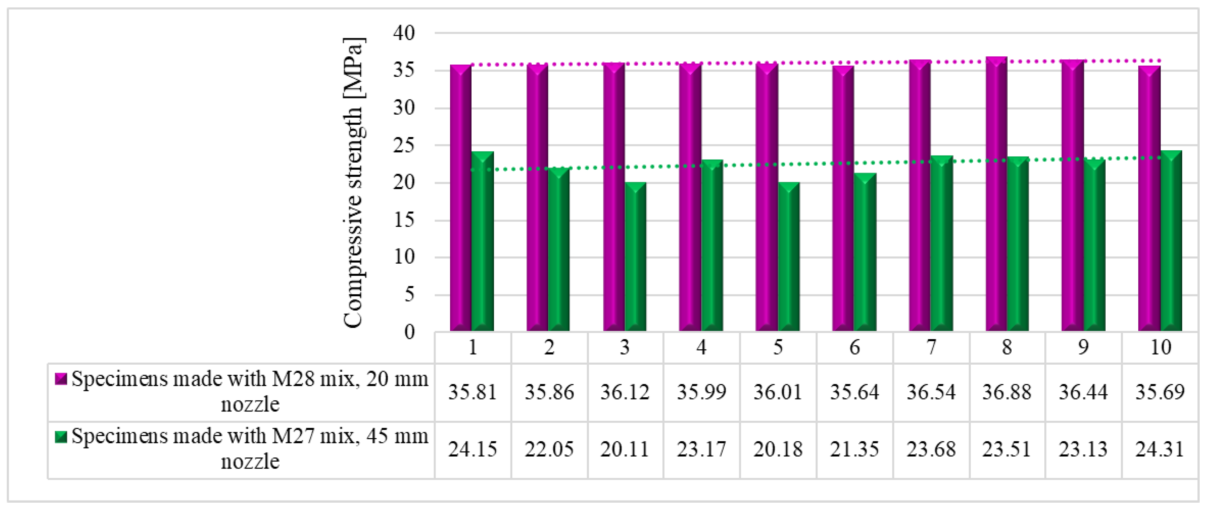
Figure 25.
Average compressive and flexural strengths.
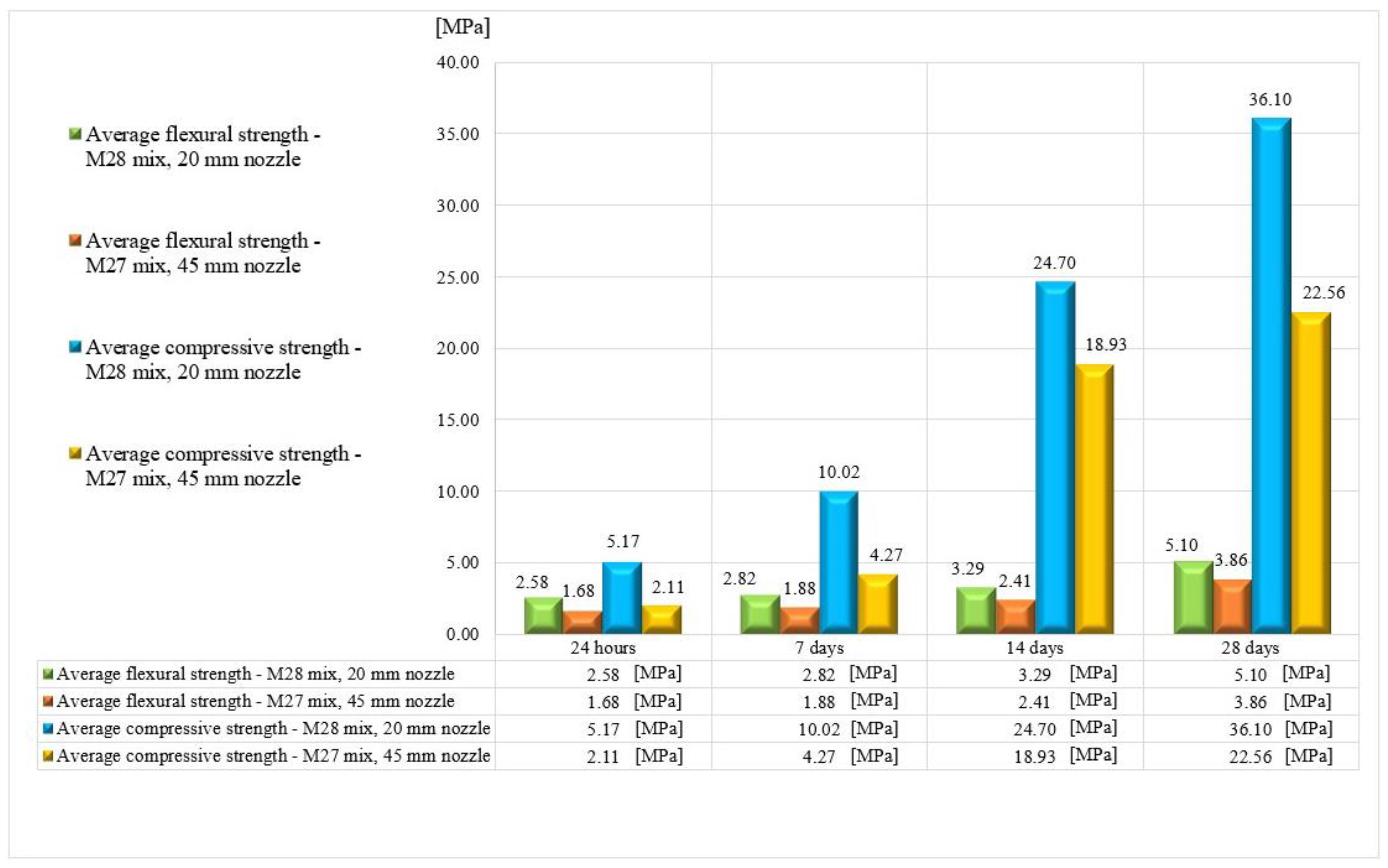
Figure 26.
Proposed locations of the reinforcements in the 3D printed mortar structure: into the layer, across the layers, and perpendicular to the layers.
Figure 26.
Proposed locations of the reinforcements in the 3D printed mortar structure: into the layer, across the layers, and perpendicular to the layers.


Table 1.
Material mixing methods.
| Method 1 | Prepared in a pan mixer with constant speed |
| Step 1 | Weighing all the materials. This step is common for all the methods thus, it will not be repeated in the next sections of this table. |
| Step 2 | The viscosity modifying agent and the plasticizer were mixed in two separately glass containers with 1/3 water (calculated based on the agent’s mass) taken from the total water amount. This step is common for all the methods thus, it will not be repeated in the next sections of this table. |
| Step 3 | Mixing the sand, the limestone filler and the polypropylene fibers for 5 minutes. |
| Step 4 | Adding half of the water and mixing for 5 minutes. |
| Step 5 | Mixture settled for 5 minutes. This step is common for all the methods thus, it will not be repeated in the next sections of this table. |
| Step 6 | Adding the cement and the rest of the water. Mixing for 5 minutes. |
| Step 7 | Adding the viscosity modifying agent and the plasticizer. Mixing for 5 minutes. |
| Method 2 | Prepared in a site concrete mixer with constant speed |
| Step 3 | Mixing the sand, the limestone filler and the polypropylene fibers for 5 minutes. The fibers were manually dispersed before adding. During the mixing time, the drum was constantly tilted between 30o and 50o. |
| Step 4 | Adding half of the water and mixing for 5 minutes. During the mixing time, the drum was constantly tilted between 30o and 50o. |
| Step 6 | Adding the cement and the rest of the water. Mixing for 5 minutes. |
| Step 7 | Adding the viscosity modifying agent and the plasticizer. Mixing for 7 minutes. |
| Method 3 | Prepared in a cylindrical tank using a handheld electrical mortar mixer with adjustable speed |
| Step 3 | Mixing the sand, the limestone filler and the polypropylene fibers for 5 minutes. The speed was gradually increased up to 350 RPM. A cylindrical tank was used to avoid material trapping at corners. |
| Step 4 | Adding half of the water and mixing for 5 minutes at 500 RPM. |
| Step 6 | Adding the cement and the rest of the water. Mixing for 5 minutes at 700 RPM. |
| Step 7 | Adding the viscosity modifying agent and the plasticizer. Mixing for 7 minutes at 700 RPM. |
Table 2.
Mix formulations – quantities per cubic meter.
| Mix | Sand [kg] | Cement [kg] |
Limestone filler [kg] |
Fibers [kg] | Superplasticizer [%] |
Viscosity modifying agent [%] |
Water [l] |
W/C |
| M1 | 1358 | 580 | 200 | 7 | 1.2 | 0.2 | 200 | 0.345 |
| Extrudability | The M1 mix could not be extruded. Blockage occurred in the pump feeder shaft. | |||||||
| Mix | Sand [kg] | Cement [kg] |
Limestone filler [kg] |
Fibers [kg] | Superplasticizer [%] |
Viscosity modifying agent [%] |
Water [l] |
W/C |
| M2 | 1358 | 580 | 200 | 5 | 1.2 | 0.2 | 200 | 0.345 |
| Extrudability | The M2 mix could not be extruded. Blockage occurred in the pump feeder shaft. | |||||||
| Mix | Sand [kg] | Cement [kg] |
Limestone filler [kg] |
Fibers [kg] | Superplasticizer [%] |
Viscosity modifying agent [%] |
Water [l] |
W/C |
| M3 | 1358 | 580 | 200 | 3 | 1.2 | 0.2 | 200 | 0.345 |
| Extrudability | The M3 mix could not be extruded. Blockage occurred either in the pump feeder shaft or in the outlet unit. | |||||||
| Mix | Sand [kg] | Cement [kg] |
Limestone filler [kg] |
Fibers [kg] | Superplasticizer [%] |
Viscosity modifying agent [%] |
Water [l] |
W/C |
| M4 | 1358 | 580 | 200 | 1 | 1.2 | 0.2 | 200 | 0.345 |
| Extrudability | The M4 mix could be extruded but blockages still occurred. Thus, the water quantity was gradually increased starting from a step of 5 l/m3. The final quantity of water (265 l) corresponds to the M17 mix. | |||||||
| Mix | Sand [kg] | Cement [kg] |
Limestone filler [kg] |
Fibers [kg] | Superplasticizer [%] |
Viscosity modifying agent [%] |
Water [l] |
W/C |
| M17 | 1358 | 580 | 200 | 1 | 1.2 | 0.2 | 265 | 0.457 |
| Extrudability | The M17 mix could be extruded without blockages. | |||||||
| Buildability | The M17 mixture cannot be printed as large deformations occurred in the bottom layers. The mix is too fluid, the percentage of viscosity modifying agent was increased by 0.1 %. | |||||||
| Mix | Sand [kg] | Cement [kg] |
Limestone filler [kg] |
Fibers [kg] | Superplasticizer [%] |
Viscosity modifying agent [%] |
Water [l] |
W/C |
| M18 | 1358 | 580 | 200 | 1 | 1.2 | 0.3 | 265 | 0.457 |
| Extrudability | The M18 mix could be extruded without blockages. | |||||||
| Buildability | The M18 mixture cannot be printed as large deformations occurred in the bottom layers. The mix is too fluid, the percentage of viscosity modifying agent was increased by 0.1 %. | |||||||
| Table continued on the next page ↓ | ||||||||
| Mix | Sand [kg] | Cement [kg] |
Limestone filler [kg] |
Fibers [kg] | Superplasticizer [%] |
Viscosity modifying agent [%] |
Water [l] |
W/C |
| M19 | 1358 | 580 | 200 | 1 | 1.2 | 0.4 | 265 | 0.457 |
| Extrudability | The M19 mix could be extruded without blockages. | |||||||
| Buildability | The M19 mixture cannot be printed as large deformations still occurred in the bottom layers. The mix is too fluid, the percentage of viscosity modifying agent was increased by 0.2 %. | |||||||
| Slump flow | 150 mm | |||||||
| Mix | Sand [kg] | Cement [kg] |
Limestone filler [kg] |
Fibers [kg] | Plasticizer [%] |
Viscosity modifying agent [%] |
Water [l] |
W/C |
| M20 | 1358 | 580 | 200 | 1 | 1.2 | 0.6 | 265 | 0.457 |
| Extrudability | The M20 mix could be extruded without blockages. | |||||||
| Buildability | The M20 mixture cannot be printed as large deformations still occurred in the bottom layers. The mix is too fluid, the percentage of viscosity modifying agent was increased by 0.2 %. | |||||||
| Slump flow | 140 mm | |||||||
| Mix | Sand [kg] | Cement [kg] |
Limestone filler [kg] |
Fibers [kg] | Plasticizer [%] |
Viscosity modifying agent [%] |
Water [l] |
W/C |
| M21 | 1358 | 580 | 200 | 1 | 1.2 | 0.8 | 265 | 0.457 |
| Extrudability | The M21 mix could be extruded without blockages. | |||||||
| Buildability | The M21 mixture could be printed. | |||||||
| Slump flow | 110 mm | |||||||
| Printability | The open time of the M21 mix is too high. Thus, the quantity of water was gradually reduced by 5l/m3. The final quantity of water (245 l) corresponds to the M25 mix. Also, the percentage of plasticizer was increased by 0.2 %. | |||||||
| Mix | Sand [kg] | Cement [kg] |
Limestone filler [kg] |
Fibers [kg] | Plasticizer [%] |
Viscosity modifying agent [%] |
Water [l] |
W/C |
| M25 | 1358 | 580 | 200 | 1 | 1.4 | 0.8 | 245 | 0.422 |
| Extrudability | The M25 mix could not be extruded. Blockage occurred either in the pump feeder shaft or in the outlet unit. The quantity of water was gradually increased by 5l/m3. The final quantity of water (255 l) corresponds to the M27 mix. The plasticizer was reduced by 0.2 %. | |||||||
| Slump flow | 135 mm | |||||||
| Mix | Sand [kg] | Cement [kg] |
Limestone filler [kg] |
Fibers [kg] | Plasticizer [%] |
Viscosity modifying agent [%] |
Water [l] |
W/C |
| M27 | 1358 | 580 | 200 | 1 | 1.2 | 0.4 | 255 | 0.440 |
| Extrudability | The M27 mix could be extruded only through the 45 mm nozzle. | |||||||
| Buildability | The M27 mixture could be printed. | |||||||
| Printability | The open time of the M27 mix is around 35 minutes. | |||||||
| Table continued on the next page ↓ | ||||||||
| Mix | Sand [kg] | Cement [kg] |
Limestone filler [kg] |
Fibers [kg] | Superplasticizer [%] |
Viscosity modifying agent [%] |
Water [l] |
W/C |
| M28 | 1358 | 580 | 200 | 1 | 1.1 | 0.4 | 265 | 0.457 |
| Extrudability | The M28 mix could be extruded through the 18-, 20-, 25- and 45-mm nozzles. | |||||||
| Buildability | It was found that the M28 mix can build more than 100 layers without showing any type of failure. | |||||||
| Printability | The open time of the M28 mix is around 40 minutes. The optimum printing speed was limited to 100 mm/s to print layers with the same width as the nozzle smallest inlet (18 mm). | |||||||
| Slum flow | 160 mm | |||||||
| Slump | 40 mm | |||||||
| Density | 2249 kg/m3 | |||||||
Disclaimer/Publisher’s Note: The statements, opinions and data contained in all publications are solely those of the individual author(s) and contributor(s) and not of MDPI and/or the editor(s). MDPI and/or the editor(s) disclaim responsibility for any injury to people or property resulting from any ideas, methods, instructions or products referred to in the content. |
© 2023 by the authors. Licensee MDPI, Basel, Switzerland. This article is an open access article distributed under the terms and conditions of the Creative Commons Attribution (CC BY) license (http://creativecommons.org/licenses/by/4.0/).
Copyright: This open access article is published under a Creative Commons CC BY 4.0 license, which permit the free download, distribution, and reuse, provided that the author and preprint are cited in any reuse.


