
Submitted:
22 June 2023
Posted:
25 June 2023
You are already at the latest version
Abstract
Significant design efforts were undertaken during the Pre-Concept Design (PCD) phase of the European DEMO programme to optimize the Helium Cooled Pebble Bed (HCPB) breeding blanket. A gate review was conducted for the entire European DEMO programme at the conclusion of the PCD phase. This article presents a summary of the design evolution and the rationale behind the HCPB breeding blanket concept for the European DEMO. The main performance metrics, including nuclear, thermal hydraulics, thermal mechanical, and tritium permeation behaviors, are reported. These figures demonstrate that the HCPB breeding blanket is a highly effective tritium-breeding and robust driver blanket concept for the European DEMO. In addition, three alternative concepts of interest were explored. Furthermore, this article outlines the upcoming design and R&D activities for the HCPB breeding blanket during the Concept Design phase (2021-2027).
Keywords:
European DEMO
; Helium Cooled Pebble Bed
; Tritium Breeding Blanket
; Fusion
1. Introduction
With the construction of ITER ongoing, a fusion demonstration power plant (DEMO) leading towards fusion electricity is the next focus of attention within the European fusion community [1]. The European DEMO is based on the tokamak line with D-T fusion reaction in the plasma. Among other objectives, it is aiming to produce net fusion electricity and achieve fuel self-sufficiency [2]. The breeding blanket (BB) is one key system among all DEMO systems to realize these two objectives. The breeding blanket surrounds approximately 80% of the plasma volume and serves three primary functions: (1) to breeding enough tritium (T) to close the fuel cycle, (2) to extract high-grade heat for electricity production and (3) to protect the components located behind it from nuclear irradiation. Unless explicitly stated otherwise, "DEMO" refers to the European DEMO, while "blanket" refers specifically to the breeding blanket, excluding the shielding blanket and test blanket module (TBM), within the context of this article.
On October 9th, 2014, organizations involved in fusion research from member states of the European Union and Switzerland signed an agreement aimed at solidifying collaboration on fusion research. This agreement led to the establishment of EUROfusion, the European Consortium for the Development of Fusion Energy [3]. EUROfusion provides financial and research support for fusion-related activities under the Euratom programme of the European Commission [3]. The phase starting from 2014 to 2020 is known as the Pre-Concept Design (PCD) Phase [4]. At the end of 2020, the whole European DEMO programme went through the so-called gate review by independent external experts groups. A gate review is a checkpoint review that decides whether a project can proceed to the next phase or not [4]. The Helium Cooled Pebble Bed (HCPB) [5] and the Water Cooled Lithium Lead (WCLL) [6] concepts are the two candidate driver blanket concepts for the European DEMO [7]. The HCPB line has been led by the Karlsruhe Institute of Technology (formerly known as KfK and FZK) in Germany since 1980s [8,9,10,11,12,13,14,15,16]. The HCPB blanket concept uses pressurized helium gas (at 8 MPa) as coolant, lithium ceramic as tritium breeder and beryllium-containing material as neutron multiplier material (NMM), the reduced-activation ferritic martensitic steel Eurofer97 as structural material and tungsten as armor on the first wall (FW). The tritium bred in the HCPB BB will be extracted through a purge gas system. This article presents the design status of the HCPB breeding blanket at the conclusion of PCD phase.
2. Design description of HCPB breeding blanket
2.1. Design evolution
The breeding blanket shall follow the space allocated in the DEMO tokamak layout. During the PCD phase, two official baselines (BLs) of the European DEMO machine were released, one called the DEMO BL2015 and the latest one called the DEMO BL2017. The design evolution of the HCPB BB is schematically shown in Figure 1.
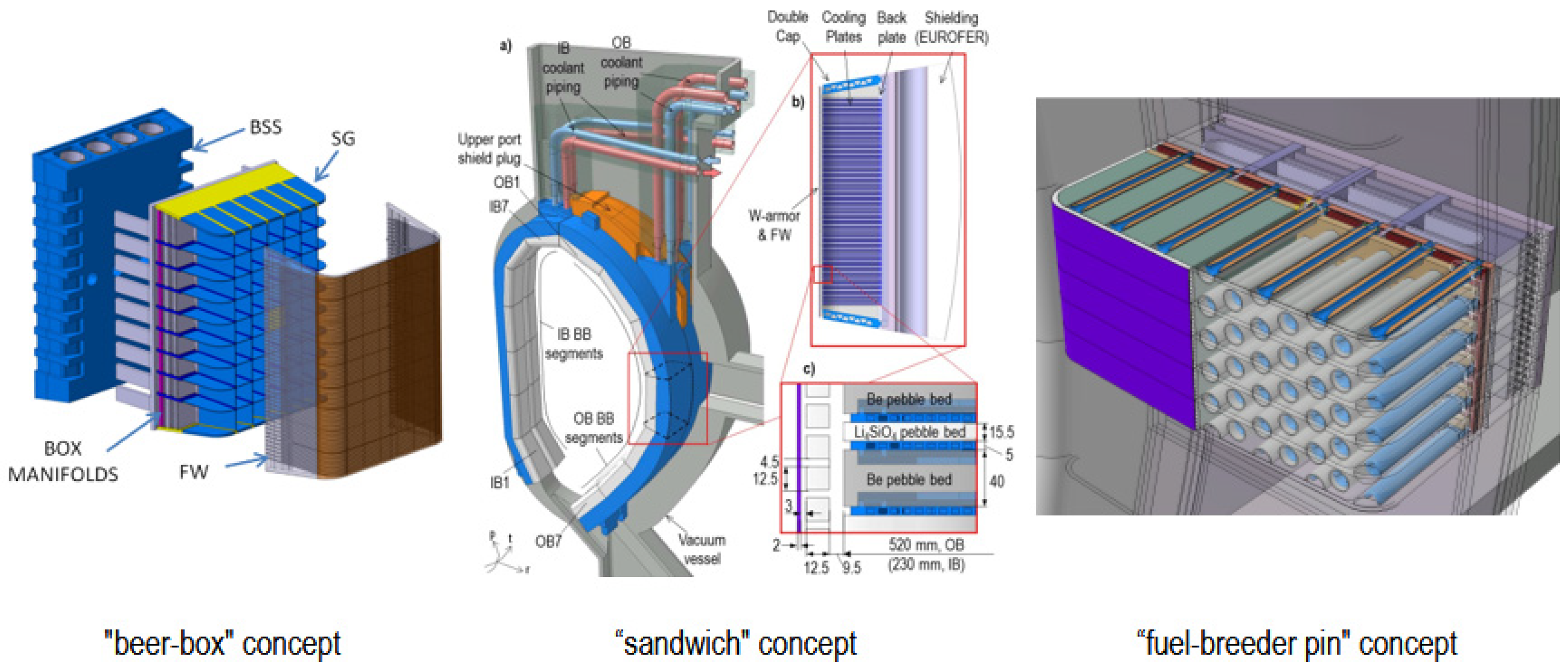
At the beginning of the PCD phase, which was in 2014, the HCPB blanket adopted the so-called "beer-box" concept [11] similar to the HCPB Test Blanket Module developed at KIT in the 2010s [17]. This concept has a very robust vertical and horizontal grid structure resulting a large amount of steel in the breeder zone, which compromises its tritium breeding performance. In order to improve the tritium breeding performance, during 2015-2016, the HCPB design has been changed to reduce the steel amount in the breeder zone (BZ). This HCPB version was called the "sandwich" concept, which has alternating layers of tritium breeder Li4SiO4 pebbles and neutron multiplier beryllium pebbles, separated by a cooling plate made of Eurofer97 [12]. The DEMO baseline at that time was the DEMO BL2015, which had 18 toroidal field coils leading to 18 blanket sectors. Each sector contained 2 inboard (IB) and 3 outboard (OB) blanket segments. Each blanket segment was consisted of 7 blanket modules, known as multi-module segment (MMS) [18]. Due to the complexity of manufacturing regarding the small-channels embedded in cooling plates and the large pressure drop of the small channels, the architecture of the HCPB blanket needed to be further improved. During 2017-2018, the novel, known as the "fuel-breeder pin" concept of HCPB was developed [16].
Meanwhile, in 2017 the latest DEMO baseline DEMO BL2017 was released. There are 16 toroidal field coils in the whole tokamak, thus subdividing the machine into 16 sectors [19]. Same as the previous division of blanket sector, there are 2 IB and 3 OB blanket segments. Since the MMS segment requires more steel in the blanket and the structural performance of MMS under electromagnetic loads is unsatisfied, the Single Module Segment (SMS) for the blanket segmentation was proposed for the DEMO BL2017.
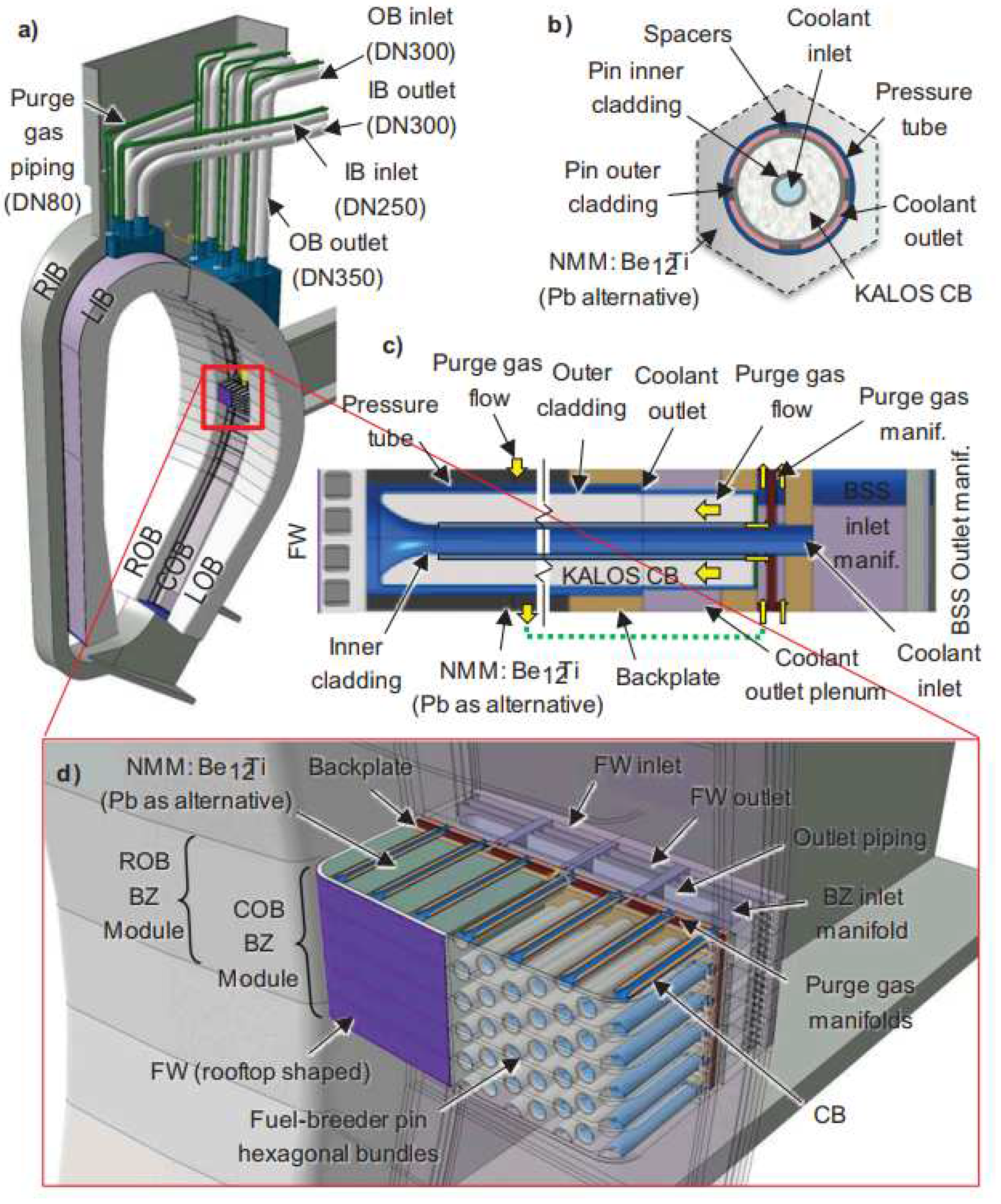
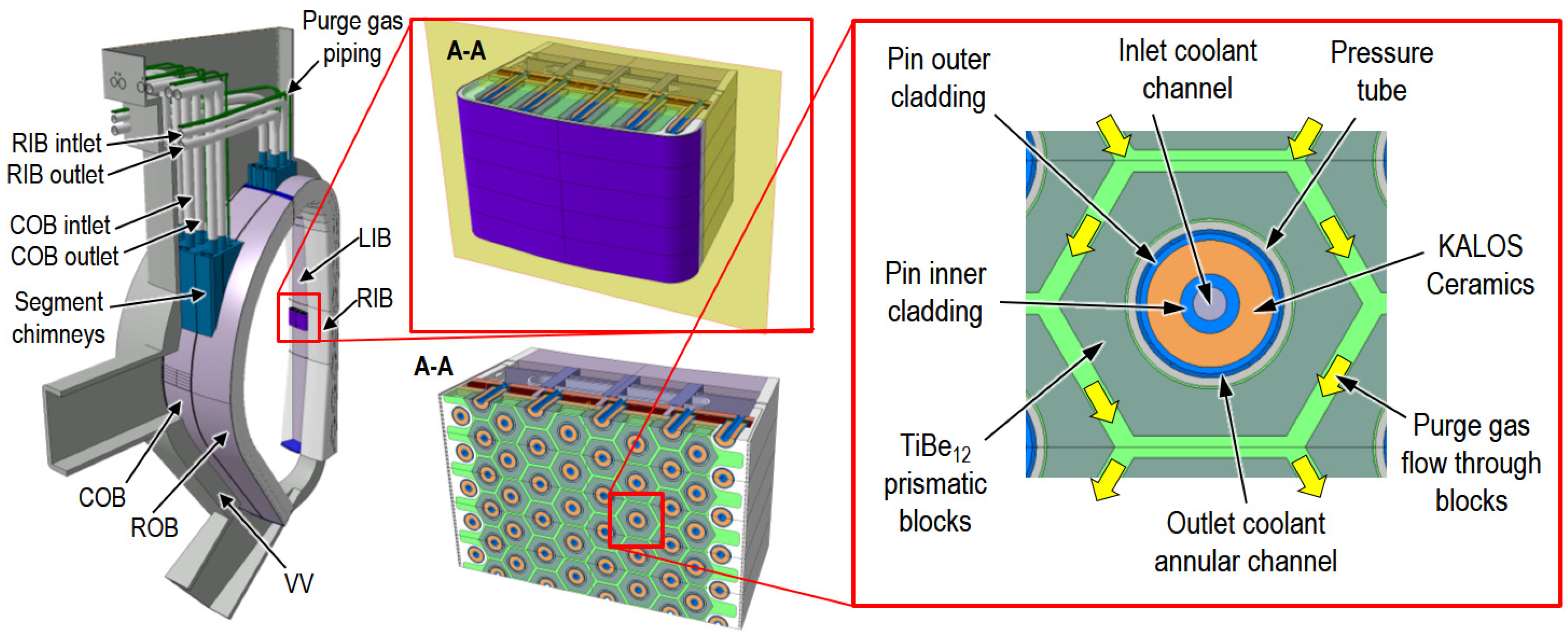
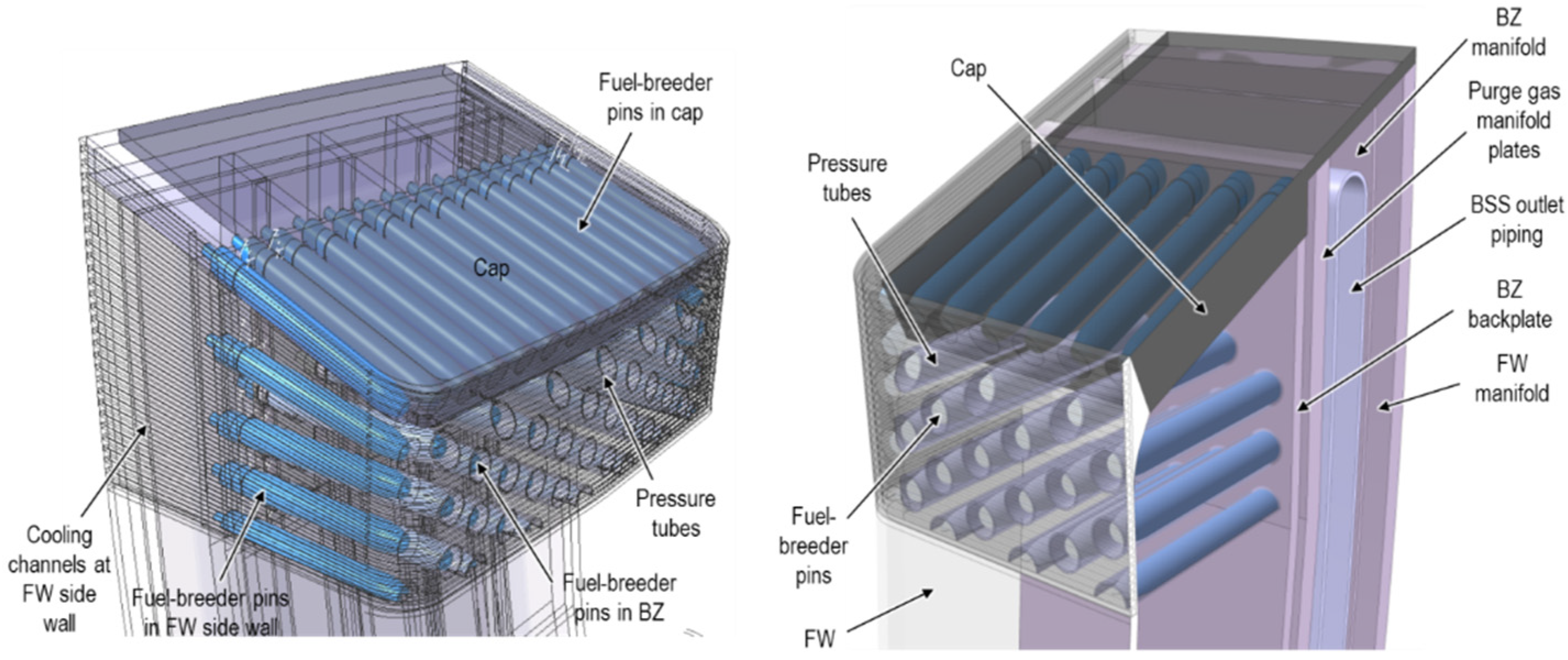
Notable changes in the fuel-breeder pin concept included the change of the functional materials. The tritium breeder material Li4SiO4 was replaced with the advanced ceramic breeder (ACB), which is a solid solution of two-phase materials consisted of Li4SiO4 and about 35% mol. Li2TiO3. The ACB bed, which is also known as KALOS, are in form of pebbles with an average diameter of 750 µm instead of the previous 350 µm of Li4SiO4. This kind of lithium ceramic material developed at KIT during 2010s [20] has better crush load and tritium release performance. The neutron multiplier beryllium pebble was replaced with beryllide (TiBe12 as reference material and CrBe12 as backup) block. In the following, some selective reasons for the mentioned design update are given. In pure beryllium, a significant fraction of generated tritium (up to 100% below 500°C) is trapped within helium bubbles (relevant temperature of beryllium in HCPB BB) [21] which is a safety concern. The use of pure beryllium poses also a risk in the case of a postulated accidental scenario involving water ingress (from failed water-cooled divertors and/or limiters) or air ingress into a failed blanket box exposing beryllium material. Additionally, the production of about 300 tons of Be or Beryllide pebbles required for the European DEMO is not feasible by using the reference fabrication method, e.g. rotating electrode method. The reason that pebble bed form instead of a slab or block form was favoured before 2017 was to limit the swelling and cracking of the beryllium material. With very low swelling of beryllide material, it is possible to use the slab or block form in BB. Therefore, the hexagonal prismatic beryllide block is used in the "fuel-breeder pin" concept, shown in Figure 2 [16]. In fuel-breeder pin concept, there are two concentric tubes, a small one and a large one, forming the cladding of the ACB pebbles. On one side, the two tubes are connected by a reversed funnel, and the space between them is filled up by the ACB pebbles. Outside these two concentric tubes there is a larger concentric pressure tube, forming the annular cooling channel together with the cladding.
Figure 2.
Fuel-breeder pin concept of the HCPB BB: (a) one sector showing the right-inboard, left-inboard, central outboard, and left outboard segments; (b) transversal cross-section view of a fuel-breeder pin; (c) longitudinal cross-section view of a fuel-breeder pin; (d) isometric cut-out view of a central-outboard fuel-breeder pin assembly [16].
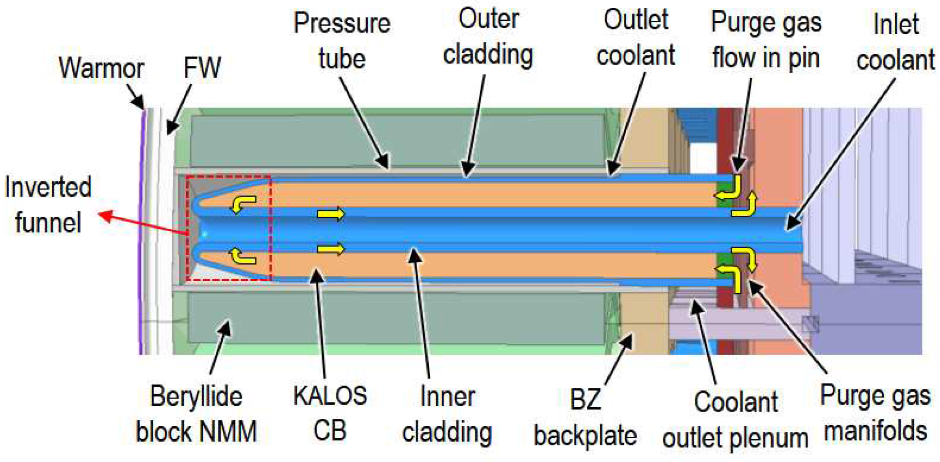
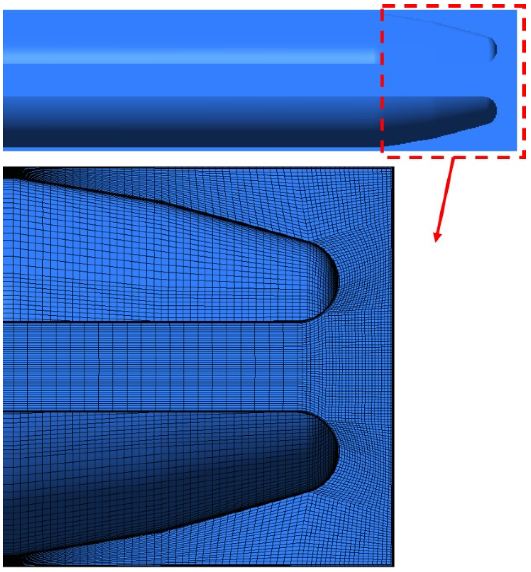
In the CFD analyses conducted for the design of a thermal hydraulic mock-up [22], it was found that the distance between the nozzle exit and the solid surface in the funnel region plays an important role for the flow stability there. The shorter distance leads to more stable flow. Therefore, in 2019, the funnel shape was inverted that the fuel-breeder pin resembles a ballpoint pen to achieve more homogenous flow, shown in Figure 3.
Figure 3.
Detailed view of a fuel-breeder pin with inverted funnel shape.
2.2. Layout at end of PCD phase
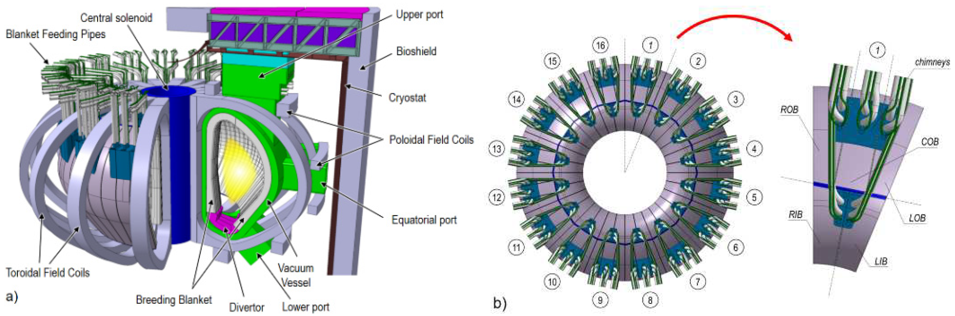
The DEMO BL2017 design has a major radius of 9 m and minor radius of 2.9 m [23], shown in Figure 4. As already mentioned, it has 16 toroidal field superconducting coils, dividing the machine into 16 sectors.
Figure 4.
DEMO BL2017 configuration: (a) Isoview of DEMO BL2017; (b) Top view of DEMO BL2017 and blanket sector.
Figure 4.
DEMO BL2017 configuration: (a) Isoview of DEMO BL2017; (b) Top view of DEMO BL2017 and blanket sector.
The CAD design of the HCPB BB at the end of the PCD phase is depicted in Figure 5. The outer contour of the blanket segment is formed by the stiff FW and the Back Supporting Structure (BSS) steel structures made of Eurofer97. The FW has a toroidal rooftop shape, which is introduced to protect the leading edge of FW, similar to that of ITER FW [23]. Behind the FW, there is the breeder zone, which comprises continuous arrays of triangularly arranged fuel-breeder pins surrounded by beryllide hex-blocks, see Figure 5 (A-A). At the upper region of the segment, the coolant feeding/collecting and purge gas pipes connected to the segment chimneys are routed in and out through Upper Port of the vacuum vessel (VV). The blanket segments are attached to the VV through attachment structures [24].
Figure 5.
HCPB BB at the end of PCD phase.
2.2.1. Segmentation and modularization
Each of the 16 blanket sectors is comprised of 2 IB blanket segments: left IB and right IB (LIB and RIB) and 3 OB blanket segments left OB, central OB and right OB (LOB, COB and ROB). In order to facilitate the Remote Maintenance (RM) operation, COB segments must have parallel side walls, which results in geometrically different OB segments. However, the LOB and ROB segments are kept symmetric. The LIB and RIB segments are symmetric as well. The gaps between the segments is 20 mm to allow enough tolerance for RM operation.
The modularisation of the segments is shown in Figure 6. As can be seen that due to the torus shape of the plasma chamber (hence blanket), toroidally the lateral outboard segments get smaller towards the upper and lower parts of the segments; while the central outboard segments have a constant toroidal dimension. As for inboard segments, as it goes towards the upper part, the segments get larger, also see Figure 4. The OB segments are divided in 17 regions (not physically separated). The region 17 has been subdivided into 3 sub-regions (L/C/ROB17.1, L/C/ROB17.2 and L/C/ROB17.3) to have a finer detail of the thermo-hydraulic characterization in these regions. The IB segments have been divided in 12 regions, where the regions 1 and 3 are subdivided into 3 sub-regions (L/RIB1.1, L/RIB1.2, L/RIB1.3 and L/RIB3.1, L/RIB3.2, L/RIB3.3) and the region 2 into 2 sub-regions (L/RIB2.1 and L/RIB2.2). The rooftop angle of the FW is 174° at the OB and 170° at the IB, with a bending radius of 2000 mm. The fuel-breeder pins in every BZ region are perpendicular to the FW in that region. All the plates behind the BZ (backplate, purge gas manifold plates and outlet piping) are designed parallelly to the FW panel at that region. Yet, the BSS follows the VV contour.
Figure 6.
HCPB BB modularization: BB regions nomenclature.
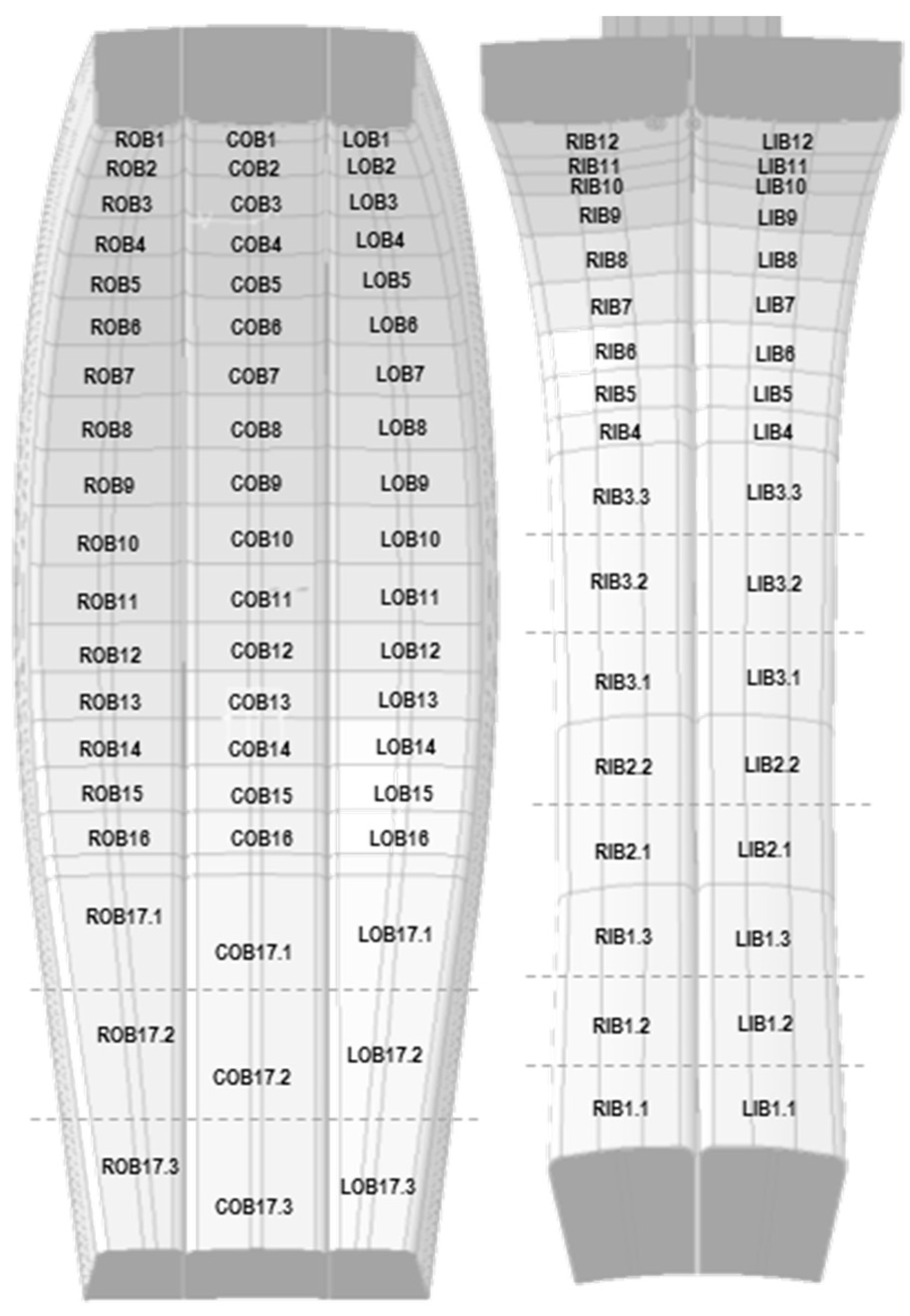
The general FW dimensions per BB regions of L/ROB and L/RIB segments are summarized in Table 1 and Table 2, respectively. The FW dimensions per BB regions of COB segment have the same poloidal and radial dimensions with those of L/ROB segments. The difference is that FW of the COB segment has a constant toroidal width (1480 mm) as the side wall of FW is designed to be parallel.

Table 1.
General FW dimensions per BB region of L/ROB BB segments
| BB region | FW height (poloidal) | FW width (toroidal) | FW sidewall length (radial) |
|---|---|---|---|
| [mm] | [mm] | [mm] | |
| R/LOB1 | 531 | 947 | 485 |
| R/LOB2 | 750 | 1046 | 478 |
| R/LOB3 | 750 | 1170 | 474 |
| R/LOB4 | 625 | 1270 | 474 |
| R/LOB5 | 625 | 1355 | 488 |
| R/LOB6 | 625 | 1331 | 495 |
| R/LOB7 | 625 | 1494 | 505 |
| R/LOB8 | 625 | 1547 | 508 |
| R/LOB9 | 625 | 1585 | 510 |
| R/LOB10 | 625 | 1611 | 510 |
| R/LOB11 | 625 | 1624 | 502 |
| R/LOB12 | 500 | 1624 | 489 |
| R/LOB13 | 500 | 1612 | 461 |
| R/LOB14 | 500 | 1578 | 436 |
| R/LOB15 | 500 | 1552 | 416 |
| R/LOB16 | 500 | 1507 | 400 |
| R/LOB17.1 | 1528 | 1406 | 423 |
| R/LOB17.2 | 1528 | 1204 | 464 |
| R/LOB17.3 | 1528 | 1018 | 505 |
Table 2.
General FW dimensions per BB region of L/RIB BB segments
| BB region |
FW height (poloidal) | FW width (toroidal) | FW sidewall length (radial) |
|---|---|---|---|
| [mm] | [mm] | [mm] | |
| R/LIB12 | 1406 | 1140 | 658 |
| R/LIB11 | 1406 | 1140 | 497 |
| R/LIB10 | 1406 | 1140 | 352 |
| R/LIB9 | 1151 | 1095 | 291 |
| R/LIB8 | 1151 | 1095 | 291 |
| R/LIB7 | 1125 | 1117 | 322 |
| R/LIB6 | 1125 | 1117 | 415 |
| R/LIB5 | 1125 | 1117 | 482 |
| R/LIB4 | 375 | 1150 | 532 |
| R/LIB3.3 | 375 | 1172 | 573 |
| R/LIB3.2 | 375 | 1210 | 519 |
| R/LIB3.1 | 375 | 1263 | 498 |
| R/LIB2.2 | 375 | 1335 | 466 |
| R/LIB2.1 | 375 | 1414 | 464 |
| R/LIB1.3 | 250 | 1475 | 478 |
| R/LIB1.2 | 250 | 1536 | 488 |
| R/LIB1.1 | 531 | 1614 | 494 |
2.2.2. Design features
The key feature of this concept is based on an arrangement of the fuel-breeder pins, consisting of two concentric tubes, a small one and a large one, forming the inner and outer cladding respectively, see Figure 7. The detailed view of fuel-breeder pin is shown in Figure 3. A filter plate in form of a disc closes the volume of the pin at the back. The volume formed in the pins is filled with the ACB pebble bed with a packing factor of about 64%. The Li-6 enrichment is set to be 60% to improve the tritium breeding ratio (TBR). Despite the atomic density of Li in Li2TiO3 is lower than in Li4SiO4, the reduction in the TBR at the reference mix of 65% Li4SiO4 - 35% Li2TiO3 is less than 1%. The inner and outer cladding are joined at the front of the pin by a reversed funnel. This resulting ballpoint pen-like shape of the pin at the front is necessary to limit the temperature of the ACB in this region. The fuel-breeder pins are inserted inside a concentric, so-called pressure tube, which mechanically joins the FW with the BZ backplate. The FW is a 20 mm U-shaped and actively cooled plate facing the plasma, which is coated with 2 mm thick functional graded materials of tungsten and Eurofer97 to protect FW against plasma erosion from fast particles. The BZ is formed then by the volume between the FW and the backplate. The pressure tubes are of utter importance in this concept, as they are the structural elements that act against a pressurization of the BZ during an accidental coolant ingress in the BZ.
Figure 7.
Toroidal-radial cut of HCPB BZ.
The gap between the pressure tube and the pins forms an annular cooling channel. The coolant flows first through the inner cladding tube, passing through the reversed funnel and turns into the annular channel. The NMM placed outside the pressure tube within the blanket box, filling the rest of the BZ volume between fuel-breeder pins. The reference NMM is TiBe12 (CrBe12 as backup) in form of hexagonal prismatic blocks. Every prismatic block encloses a fuel-breeder pin, which is its heat sink. The heat transfer between the prismatic blocks and the fuel-breeder pin is restricted by means of a helium gas gap, a similar technology as in the fuel-pellets and the cladding in a fuel element of a fission power plant. The rationale for this choice instead of some interfacial material or direct join of the blocks to the pins is due to its simplicity and similar proven application in nuclear fission reactors. Scoping study varying the gap distance of TiBe12 shows that this choice is robust due to the good thermal conductivity [16]. The gap between blocks is 10 mm and responds to a desire to reduce the amount of this material. However, this distance can be reduced to at least 5 mm in order to reduce the neutron streaming, if necessary. The fact of filling the ACB pebbles in the pins is a key advantage for the controllability of the packing factor of these pebble beds. These pins might be even equipped at the back with a spring which could compensate the progressive plastic deformation of the pebble bed to avoid a possible gap formation in the pins.
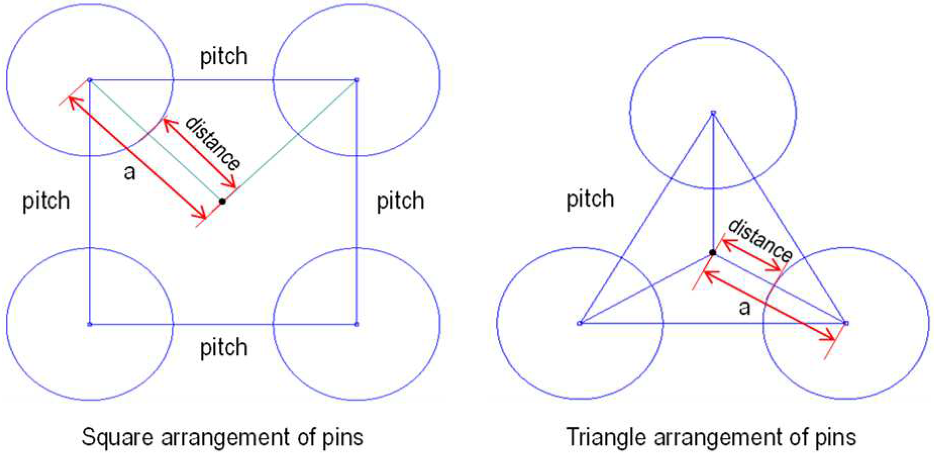
The HCPB BB design at the end of PCD phase uses a triangular arrangement for the fuel-breeder pins instead of the square arrangement, see Figure 8. The squared arrangement produces a relatively inhomogeneous temperature in the TiBe12, producing a hot spot in the TiBe12 at the square centre. The triangular arrangement mitigates this, better homogenizing the NMM temperature and better cooling for NMM. For the triangular arrangement, the longest distance from neutron multiplier centre to the cooling pin is shorter than that in a square arrangement with the same pitch between pins. For the square-arranged pins, the longest distance a from the pin centre to the neutron multiplier centre can be calculated as in Equation (1): when the pitch is 125 mm (e.g. OB pins’ pitch), this distance is 88.4 mm. For the triangular-arranged pins, the longest distance a from the pin centre to the neutron multiplier centre can be calculated as in Equation (2): when the pitch is 125 mm (e.g. OB pins’ pitch), this distance is 72.2 mm.
Figure 8.
Square and triangular arrangement of pins.
The fuel-breeder pins are welded to the backplate in cantilever position. The resulting architecture resembles a bayonet tube heat exchanger, where the fluid in the bayonet tubes (the Helium in the fuel-breeder pins) is heated by the surrounding functional and structural material instead that from a second fluid.
Behind the BZ backplate, a series of parallel plates are placed (Figure 7), which form the different manifold volumes for purge gas and coolant. Three plates behind the BZ backplate forms the purge gas manifold system (front, mid and back purge gas manifold plates). The 2 volumes formed by the purge gas manifolds corresponds to the inlet and outlet purge gas volumes. Transversal ribs (front and back ribs) are placed perpendicular to these plates, which stiffen the segment against the internal coolant pressure. The segment is closed at the back by a BSS backplate. The volume behind the purge gas manifold backplate and the BSS backplate is the BSS manifold. This volume is split by an additional plate (BSS FW separator plate), which separates the FW from the BZ manifold. The BSS outlet piping collects the coolant at the BB outlet.
Due to the uneven poloidal distribution of the heat flux, the cooling needs of the FW vary along the poloidal direction. The heat flux on the central outboard FW is 0.31 MW/m² at the bottom region near divertor, 0.27 MW/m² at equatorial region and 0.23 MW/m² at the top region. For this reason, the dimensioning and surface finish of FW channel have to be adjusted to meet the needs. The channel thickness at the plasma side is kept at 2 mm, as the poloidal width of the channel is small enough (< 15 mm) to hold the primary stress from the 8 MPa coolant pressure. The channels are equipped with augmented heat transfer structures. The fillet radii of the channels are 2.5 mm and the ribs between channels are about 4.5 mm. Table 3 summarizes the main location-dependent dimensions of the FW channels.
Table 3.
Cooling channel dimensions of the FW at different poloidal regions
| BB Region | Width (pol.) |
Height (rad.) |
BB Region | Width (pol.) |
Height (rad.) |
BB Region | Width (pol.) |
Height (rad.) |
|---|---|---|---|---|---|---|---|---|
| [mm] | [mm] | [mm] | [mm] | [mm] | [mm] | |||
| R/LOB1 | 12 | 14 | COB1 | 12 | 12 | R/LIB12 | 12 | 12 |
| R/LOB2 | 12 | 11 | COB2 | 12 | 12 | R/LIB11 | 12 | 12 |
| R/LOB3 | 12 | 11 | COB3 | 12 | 12 | R/LIB10 | 15 | 15 |
| R/LOB4 | 12 | 11 | COB4 | 12 | 12 | R/LIB9 | 15 | 15 |
| R/LOB5 | 12 | 12 | COB5 | 12 | 12 | R/LIB8 | 15 | 15 |
| R/LOB6 | 12 | 12 | COB6 | 12 | 12 | R/LIB7 | 10 | 8 |
| R/LOB7 | 12 | 12 | COB7 | 12 | 12 | R/LIB6 | 10 | 8 |
| R/LOB8 | 12 | 12 | COB8 | 12 | 12 | R/LIB5 | 10 | 8 |
| R/LOB9 | 12 | 12 | COB9 | 12 | 12 | R/LIB4 | 10 | 8 |
| R/LOB10 | 12 | 12 | COB10 | 12 | 12 | R/LIB3.3 | 10 | 8 |
| R/LOB11 | 12 | 12 | COB11 | 12 | 12 | R/LIB3.2 | 10 | 8 |
| R/LOB12 | 12 | 12 | COB12 | 12 | 12 | R/LIB3.1 | 10 | 8 |
| R/LOB13 | 12 | 12 | COB13 | 12 | 12 | R/LIB2.2 | 10 | 8 |
| R/LOB14 | 12 | 12 | COB14 | 12 | 12 | R/LIB2.1 | 10 | 8 |
| R/LOB15 | 12 | 12 | COB15 | 12 | 12 | R/LIB1.3 | 10 | 8 |
| R/LOB16 | 12 | 12 | COB16 | 12 | 12 | R/LIB1.2 | 10 | 8 |
| R/LOB17.1 | 12 | 12 | COB17.1 | 13 | 13 | R/LIB1.1 | 10 | 8 |
| R/LOB17.2 | 12 | 11 | COB17.2 | 13 | 13 | |||
| R/LOB17.3 | 12 | 11 | COB17.3 | 13 | 13 |
The blanket segments are prismatic constructions formed basically by a long, curved external shell, the U-shaped FW, and the BSS. The prism is truncated at the upper and lower ports and two so-called top and bottom caps seal the segments at these two locations. The caps (Figure 9) are massive, drilled plates in which fuel breeder pins are inserted. The internal cooling of the caps is performed by the fuel-breeder pins themselves so that no additional cooling is required. The caps, together with the U-shaped FW and the BSS forms a truncated prism that must withstand an internal pressure equal to the purge gas pressure during normal operation (NO) and the coolant pressure during an accidental scenario of an in-box loss of coolant accident (LOCA).
Figure 9.
Upper port region of the COB segment: top cap (left) and top cap section cut view (right).
Figure 9.
Upper port region of the COB segment: top cap (left) and top cap section cut view (right).
Due to the very large difference of thicknesses between the caps and the FW, a transitional part is designed at the connection region between the FW and the cap to maximize the transfer the force excerpted by the coolant pressure during an in-box LOCA as membrane stress, thus to avoid excessive bending stress on the FW.
2.2.3. Coolant choice, parameters and flow scheme
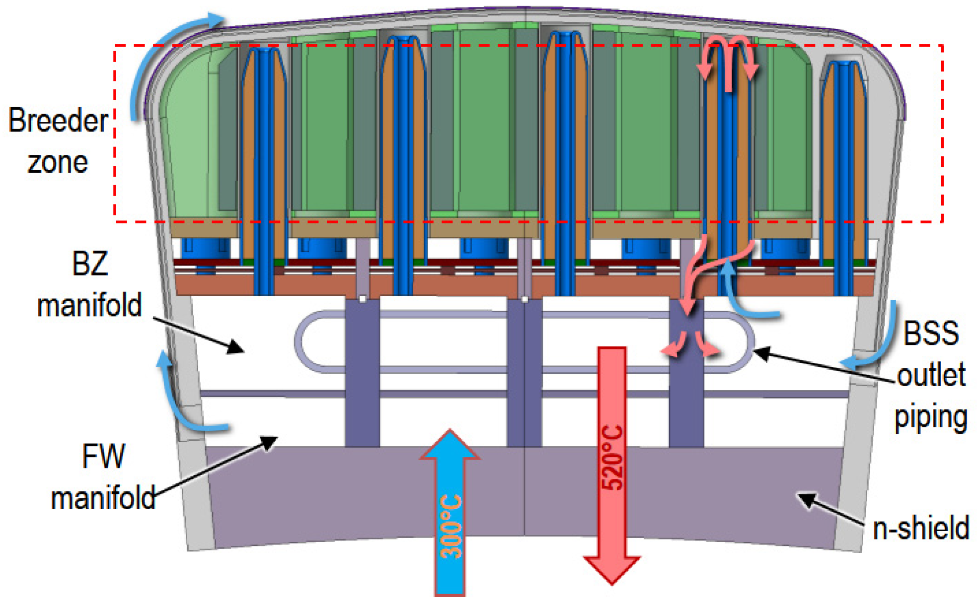
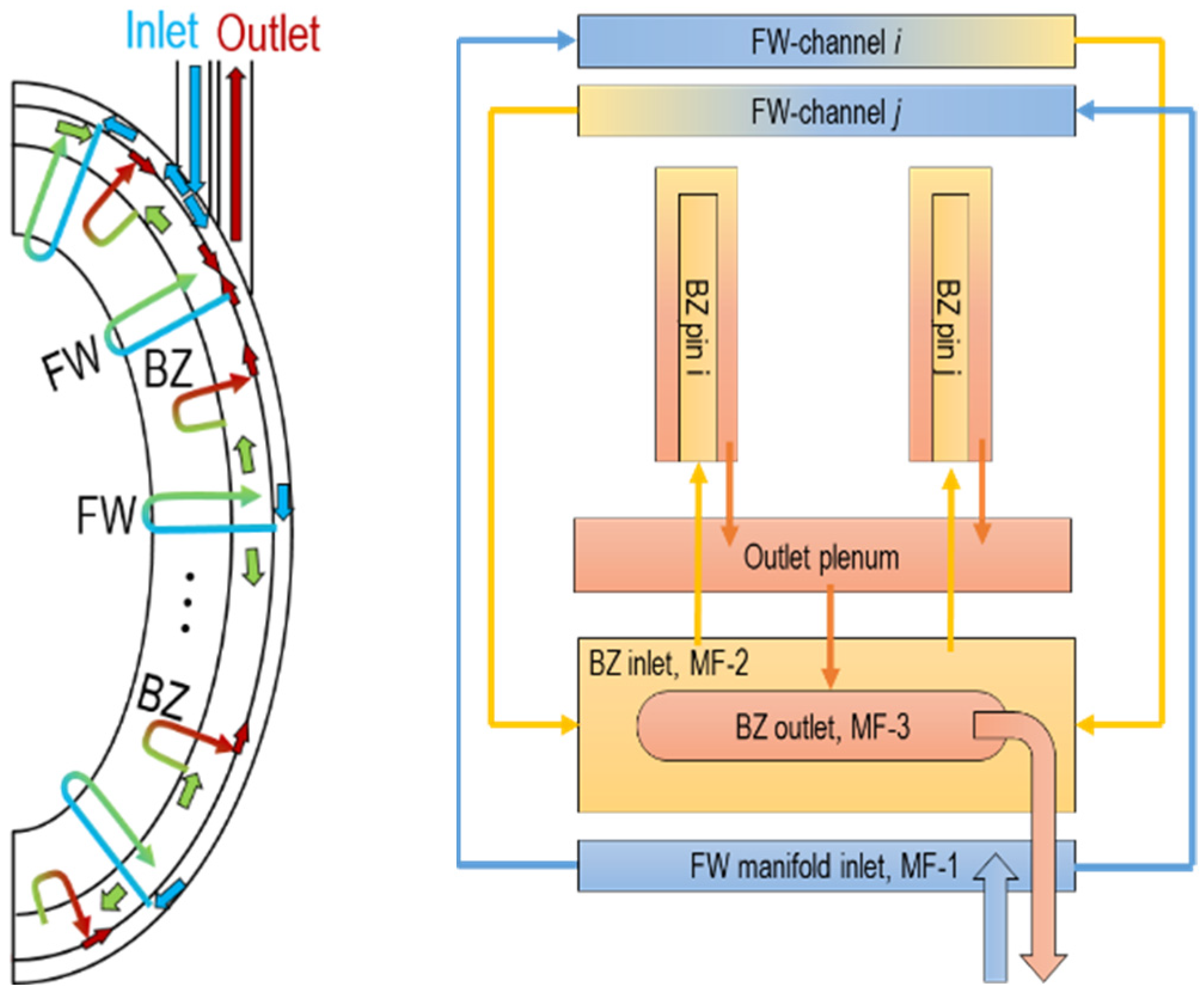
The coolant flow scheme of the HCPB BB at the end of the PCD phase is shown in Figure 10. Detailed flow scheme of in the breeder zone is also depicted in Figure 7. The helium coolant enters the segment at a temperature of 300 °C with an operating pressure of 8 MPa. Firstly, it flows from the FW manifold inlet (MF-1) to the FW cooling channels, which are cooled in a counter flow arrangement to homogenize the temperature distribution. The coolant is then collected and gets mixed in the BZ inlet manifold (MF-2). After that the coolant is distributed into the fuel-breeder pins in the BZ. The coolant is thereafter collected from the pins in the outlet plenum and redirected to the BZ outlet (MF-3), which is the outlet piping, at an expected mixed temperature of 520 °C. Gas gaps between manifolds are needed in order to thermally insulate these volumes, minimizing the heat transfer between them and ensuring the temperatures between the different stages in the BB. This kind of gap is performed by placing thin liners next to the manifold plates. The liners are connected to the manifold walls, so that the coolant reaches the gap but it creates a stagnant region, impeding convective heat transfer in this gap. The inlet and outlet of the helium pipe are located at the upper port due to the requirement of remote maintenance for the cutting and re-welding of the pipes. At the lower port, there is no sufficient space.
The non-uniform distribution of heat load requires that the mass flow be distributed smartly to have a relatively uniform temperature distribution over the blanket segment to reduce thermal stresses. In one OB blanket segment, there are 920 FW channels and 1610 fuel-breeder pins. Obtaining the correct mass flow rate is quite challenging. During PCD phase, an innovative CFD method was established to investigate the mass flow distribution and pressure drop [25].
The concept of a gas gap insulation by means of a concentric pipe has been adopted from the annular gas gap of the fuel bundle assembly in the operating CANDU reactors [26]. There, the fuel bundle is inserted into the pressure tube and the pressure tube itself is inserted into the calandria tube. Between the calandria tube and the pressure tube there is a gas gap filled with CO2, which acts as thermal insulation between the fuel bundle coolant (≈310°C) and the moderator fluid (≈60°C). Although the 250 °C temperature difference, the gap allows the thermal expansion of the pressure tube into the calandria tube and avoids the heat loss from the hot coolant to the cold moderator [26]. The same solution is foreseen for the outlet piping with helium in the gap. A thermal analysis showed that a 2 mm gap between the outlet piping and a 1 mm thick concentric liner would prevent the heat loss from the helium flowing inside the liner effectively.
Taking into account the heat balance in the blanket (, where is the thermal power in the blanket, the mass flow in the BB, the heat capacity of helium and the temperature difference between BB inlet and outlet), the increased leads to decrease of by a given thermal power. Given that the plant circulating power is almost proportional to the, a decrease in the plant circulating power is expected from the decrease of mass flow rate. Moreover, the design with a higher blanket outlet temperature will increase the thermal efficiency of the DEMO plant. Due to better heat removal in the BZ, the outlet temperature of HCPB BB can be increased from 500 °C [12] to 520 °C.
2.2.4. Purge gas choice, parameters and flow scheme
The tritium generated in the HCPB BB is extracted through the purge gas, which is helium with doping of a small fraction of H2 to enable isotopic exchange with tritium. The purge gas flow rate is a trade-off between tritium permeation rate and the size of the Tritium Extraction and Removal (TER) system. Large flow rates lead to decreased tritium residence times in the BZ and reduced permeation rates. However, this also results in the amplification of TER components, which may prove impractical from an economic and technical standpoint. The purge gas pressure has a direct impact on the TER system. The gas temperatures in the different key components of the TER system are fixed due to the process specifications. For a specified volumetric flow rate the purge gas pressure drives the mass flow rate in the components and therefore their sizes, as well as their power consumption and losses. A low purge gas pressure is then desired to minimize the mass flow rate in the TER. However, at the BZ the pressure of purge gas should be maximized in order to avoid a drop in the thermal conductivity due to the Smoluchowski effect [27,28]. In a confined environment (as in-between pebbles), the Smoluchowski effect predicts that the thermal conductivity of the gas decreases if the pressure of the gas decreases. It has been observed that the Smoluchowski effect becomes important if the purge gas pressure is below 0.15 MPa [28]. Therefore, a purge gas pressure of 0.2 MPa has been set to keep a safety margin to avoid the decrease of the thermal conductivity of the pebble bed.
For 0.2 MPa and a total flow rate of 2.36 m³/s (minimum to limit the tritium permeation to coolant), the reactor purge gas mass flow rate should be about 0.3 kg/s, which is a flow rate of 6400 Nm³/hr in normal conditions. At moment, the total purge gas flow rate in the TER system has been conservatively set to 10000 Nm³/hr (i.e. 3.73 m³/s at a temperature of 450 °C and pressure of 0.2 MPa). This flow rate has been used for the design of the HCPB TER [29]. The resulting plant purge gas mass flow rate is about 0.5 kg/s, which results in a reasonable TER system size, considered to be ready for its industrialization [29].
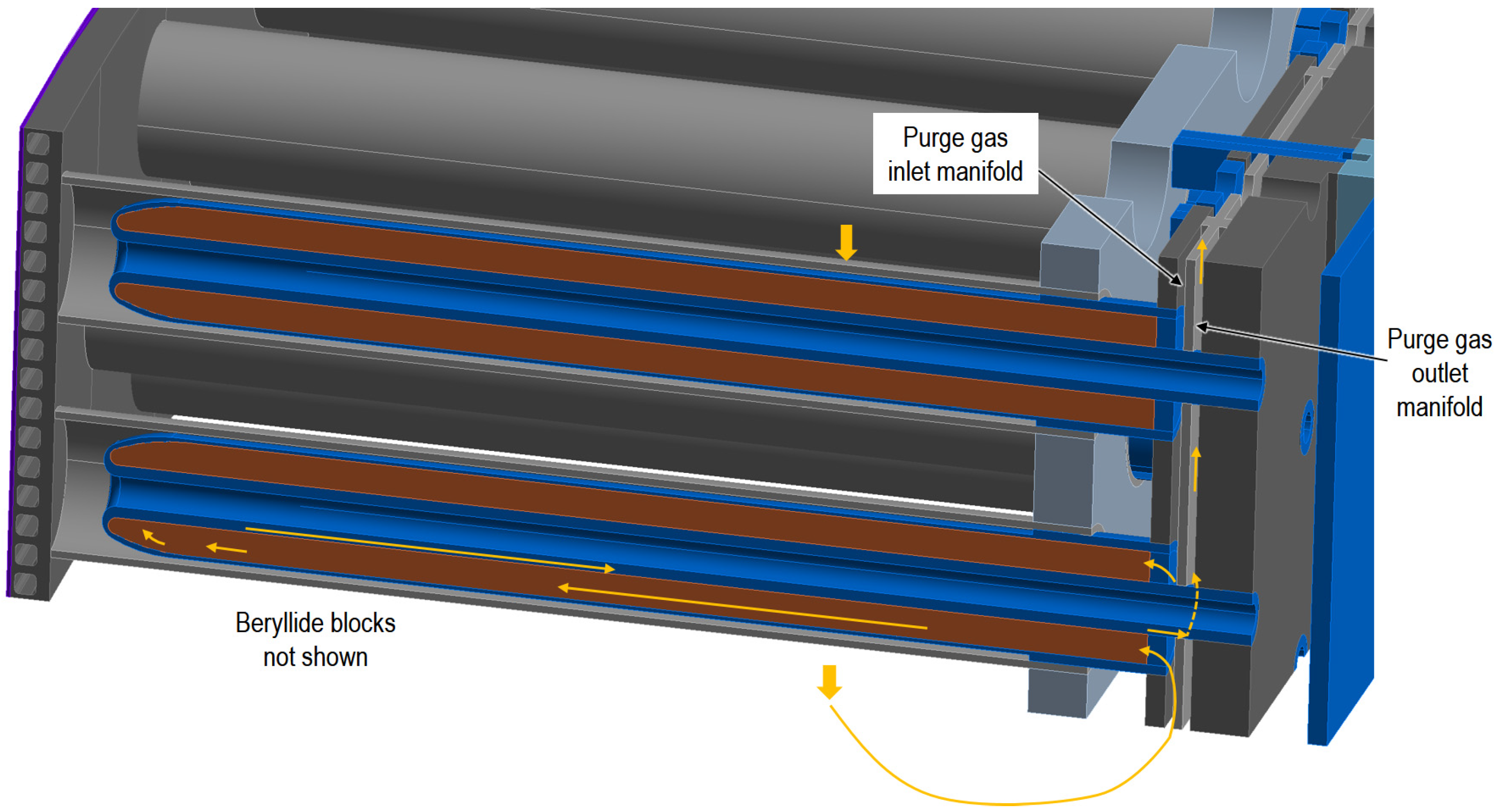
The purge gas enters the segment and flows firstly through the gaps between the beryllide blocks, see also Figure 5. Because the tritium production in beryllides is about 2 orders of magnitude lower than in the ACB pebbles, the partial pressure build-up of tritium in the purge gas is not expected to be large and presents no permeation problem. After sweeping the beryllide block, once at the bottom of the segment, the purge gas is conducted to the inlet purge gas manifold, where it is distributed in parallel to the fuel-breeder pins, from back side to the front. Once at the front, the inner cladding featuring ducts where the purge gas is routed to the outlet purge gas manifold and from there out of the segment to the corresponding purge gas piping in direction to the TER. A simplified view of purge gas flow in BZ is shown in Figure 11. Due to the difference in tritium generation between OB and IB observed in neutronics analysis, a distribution of 2/3 and 1/3 of the mass flow rate has been set for the OB and IB, respectively.
Figure 11.
Simplified view of purge gas flow in BZ (beryllides are hidden in this picture).
3. Main performance analyses
3.1. Nuclear analyses
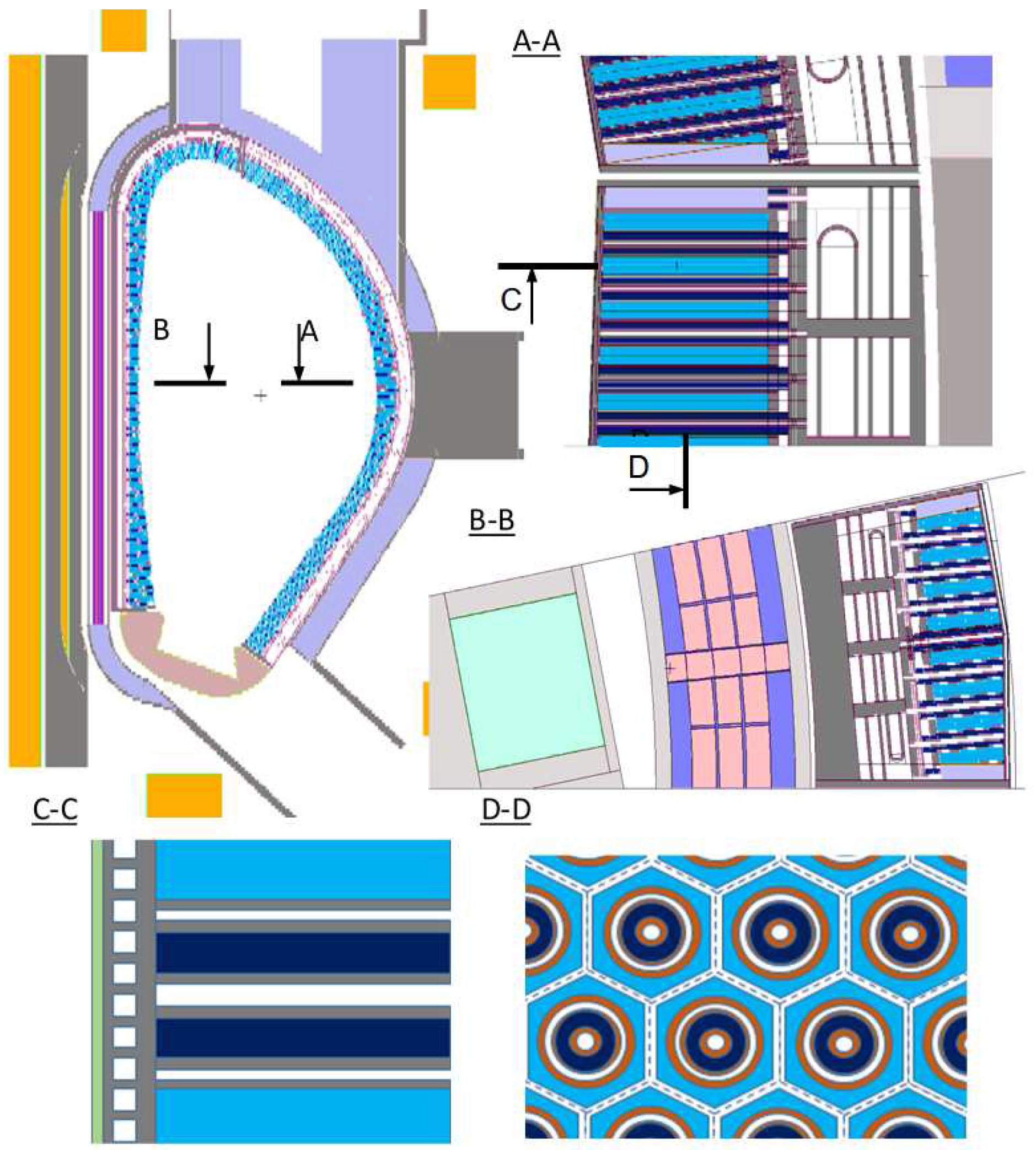
The nuclear analyses were done to assess the performance of tritium breeding ratio, nuclear heating, shielding efficiency, activation and irradiation damage of the HCPB BB. To reduce uncertainty in the modelling, it is recommended to use 3D heterogeneous model with high fidelity of the CAD design. The calculations were performed using the Monte Carlo (MC) code MCNP5-1.60 [30] with the JEFF-3.2 nuclear library [31]. At KIT, a CAD-to-MC conversion tool called McCad [32,33] has been in development since 2005, to obtain high fidelity MNCP5 models. The MCNP5 model of the HCPB BB at the end of PCD phase [34] is shown in Figure 12.
Figure 12.
MCNP5 model of the DEMO with HCPB BB: A, B – horizontal cuts in OB and IB sides; C – vertical cut in OB side in radial-poloidal direction; D – vertical cut in OB side in toroidal-poloidal direction.
Figure 12.
MCNP5 model of the DEMO with HCPB BB: A, B – horizontal cuts in OB and IB sides; C – vertical cut in OB side in radial-poloidal direction; D – vertical cut in OB side in toroidal-poloidal direction.
For heavy duty MCNP5 runs (e.g. shielding calculations) weight window variance reduction technique was applied, which ensures a statistical error less than 2% for cells outside vacuum vessel and less than 0.1% for FW cells. The maximum neutron wall loads (NWL) are about 1.12 and 1.34 MW/m² for central IB and OB respectively. The average NWL is about 0.93 MW/m² [34]. The achievable TBR of the HCPB BB at the end of PCD phase is about 1.20 (with the 0.01% of statistical uncertainty), satisfying the latest TBR requirement of 1.15 with a sufficient margin to accommodate inherent uncertainty in nuclear data and modelling simplifications and the BB coverage loss due to penetrations. The total nuclear power in the European DEMO with HCPB BB is about 2150 MW. The global energy multiplication is about 1.35 [34]. The nuclear power densities of different materials in the BB are needed as input to conduct thermal hydraulics design and analyses.
In terms of shielding and irradiation damage performance, the obtained values are within allowable limits. The reference shielding is the massive block of Eurofer97 steel at BSS. However, in order to have more margins. Different materials as alternative shielding materials were explored. The most efficient shielding materials are metallic hydrides (TiH2 and ZrH1.6) and carbides (WC, WC and B4C) [34,35]. Yet, due to the potential tritium retention issue, the hydrides might not be considered until further investigation eliminating the tritium retention and stability issues. WC is not preferred due to its heavy mass, causing problem on remote maintenance. B4C is an attractive option as it is also used in the shielding material for the diagnostics ports of ITER [36].
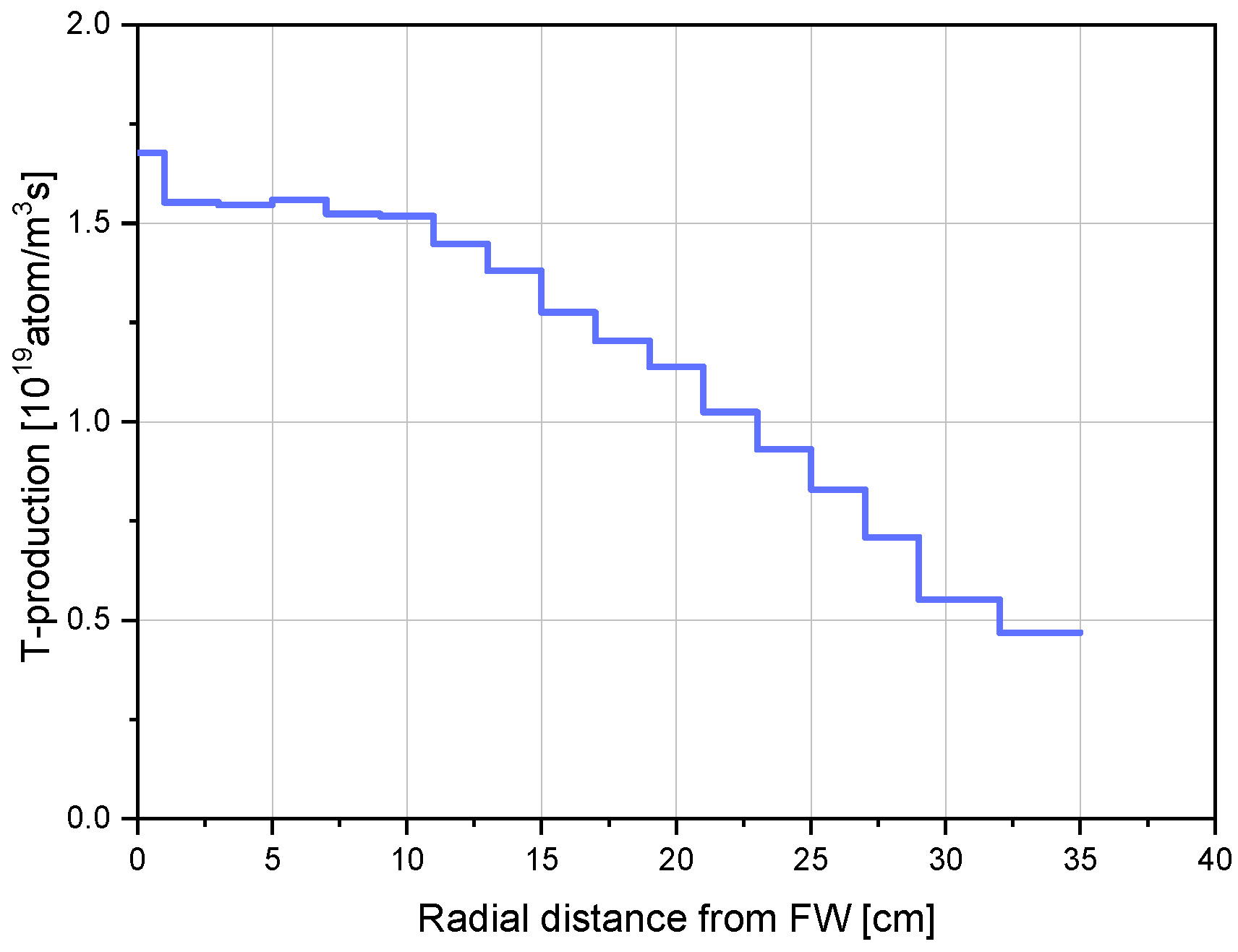
The tritium generation rate as a function of radial distance in the BB, shown in Figure 13, is needed as input for tritium transport analyses.
Figure 13.
Tritium generation rate profile at mid-plane of IB blanket.
In addition, a comprehensive activation analysis for the HCPB BB was conducted to check the radioactive level of different materials after replaced from the reactor. Following the standard EU-DEMO operation, the tungsten and Eurofer97 would be classified as Low Level Waste after 50 and 200 years. TiBe12 would be treated as Intermediate Level Waste up to 1000 years. About 75 ton of ceramic breeder would be Low Level Waste after 1 week [37].
The gaps between TiBe12 block play a role in the tritium breeding and shielding performance. To obtain higher TBR, it is wished that the neutrons reach to the rear part of the breeder zone. While to have a better shielding performance, neutrons are wished to be moderated and absorbed. A balance has been found to achieve high TBR and sufficient shielding performance, shown above.
3.2. Thermal hydraulic analyses
The thermal hydraulics on a whole COB blanket segment of HCPB BB have been intensively studied. A porous media approach for calculating the mass flow distribution and pressure drop of the COB segment was proposed using 3D CFD software [25]. The pressure drop of the COB segment is about 0.799 bar, which reduces the circulating power from the previous 150 MW [12] to 90 MW. The mass flow rate distribution in the FW channels and pins points out that orifices will be needed to optimise the distribution. An innovative method for calculating the temperature field of the COB segment was proposed and verified in [25]. Using this method, the temperature distribution on the COB segment was obtained considering the variable poloidal distribution of heat flux on the FW. It showed the helium cooled FW was able to handle a peak heat flux up to 1.256 MW/m². In addition, a comprehensive system level thermal hydraulics analysis using RELAP5-3D was conducted to investigate the thermal hydraulics behaviours under normal and accidental conditions, see [38]. During PCD phase, different experimental investigations of a HCPB FW mockup [39,40,41] and breeder zone mockup [42,43] were performed for validating CFD codes and system codes (RELAP5-3D and Melcor),
3.2.1. Mesh independence analysis
For numerical simulations, the mesh independence study is needed. For the sake of brevity, the mesh independence analysis done on the FW is shown. Similar studies were conducted for other parts. Five numerical meshes with different cross-sectional and axial resolutions have been investigated, shown in Figure 14. The number of mesh nodes and elements are reported in Table 4.
Figure 14.
Resolution of the investigated numerical meshes.
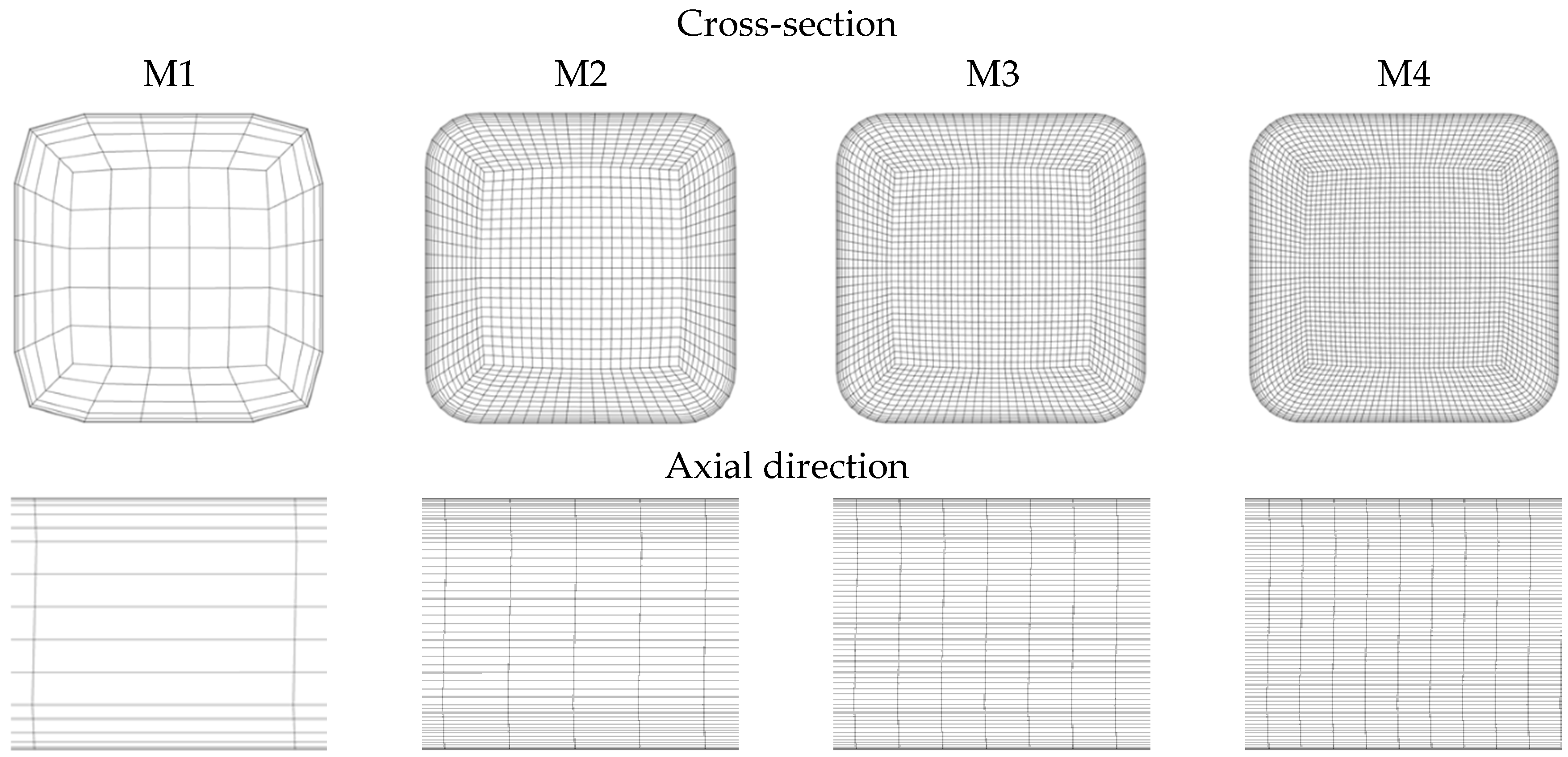
Table 4.
Number of mesh nodes and elements
| M1 | M2 | M3 | M4 | |
|---|---|---|---|---|
| Mesh nodes | 37 944 | 1 603 119 | 4 054 018 | 8 003 677 |
| Mesh elements | 35 060 | 1 560 800 | 3 960 900 | 7 840 000 |
The mesh independency analysis has been performed with a helium mass flow rate of 35 g/s. The reference pressure was set to 8 MPa. The surface roughness of the FW cooling channel was set to 40 µm. The calculated pressure drops, and the percentage differences are collected in Table 5. The M4 mesh is selected as the reference because its mesh resolution is the finest. The results of the other meshes are compared to the pressure drop calculated with M4. It can be concluded that the pressure drop is very similar in the case of M2-M4 meshes; a higher deviation can be observed in the case of M1. The conclusion is that M2-M4 meshes give nearly the same pressure drop; the mesh resolution of M2 has been selected for the further analyses.
Table 5.
Comparison of the results with different meshes
| Number of mesh nodes | Pressure drop [Pa] | Difference from M5 [%] | |
|---|---|---|---|
| M1 | 37 944 | 37 740 | -4.259 |
| M2 | 1 603 119 | 36 020 | 0.493 |
| M3 | 4 054 018 | 36 112 | 0.24 |
| M4 | 8 003 677 | 36 199 | 0 |
3.2.2. Detailed CFD analysis on the representative unit slice
Detailed CFD analyses on the representative unit slice at equatorial region of the LIB and COB have been done. The mesh of the COB unit slice (only solid domain is shown for visibility) is shown in Figure 15. Most of the regions were meshed with hexahedral elements, totally there are about 20.4 and 23.4 million elements in the LIB and COB unit slice, respectively. The fluid domains were meshed using all hexahedral elements with appropriate boundary layers, details partially shown in Figure 16 and Figure 17.
Figure 15.
Mesh of COB unit slice.
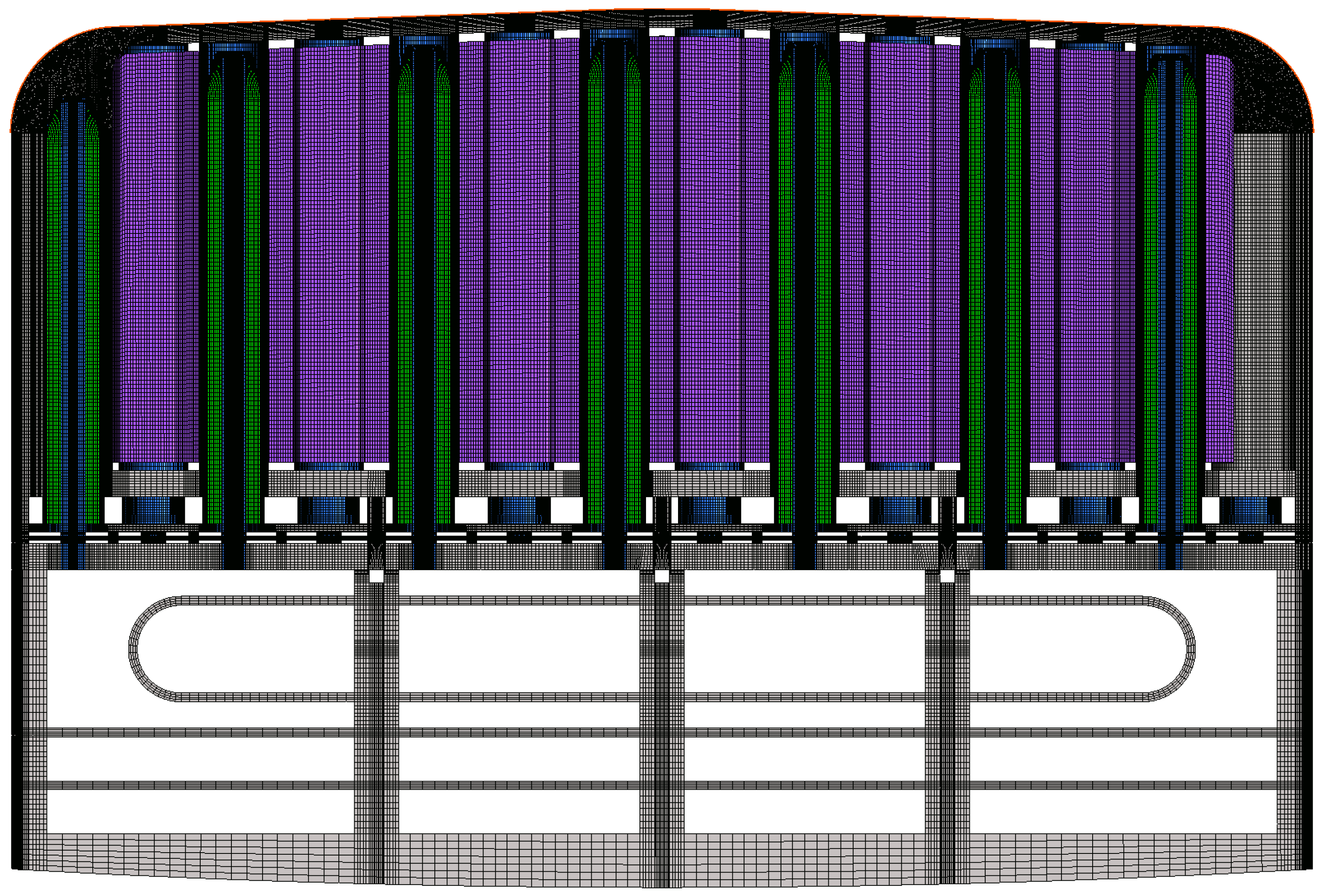
Figure 16.
Mesh of FW fluid domain of COB unit slice.
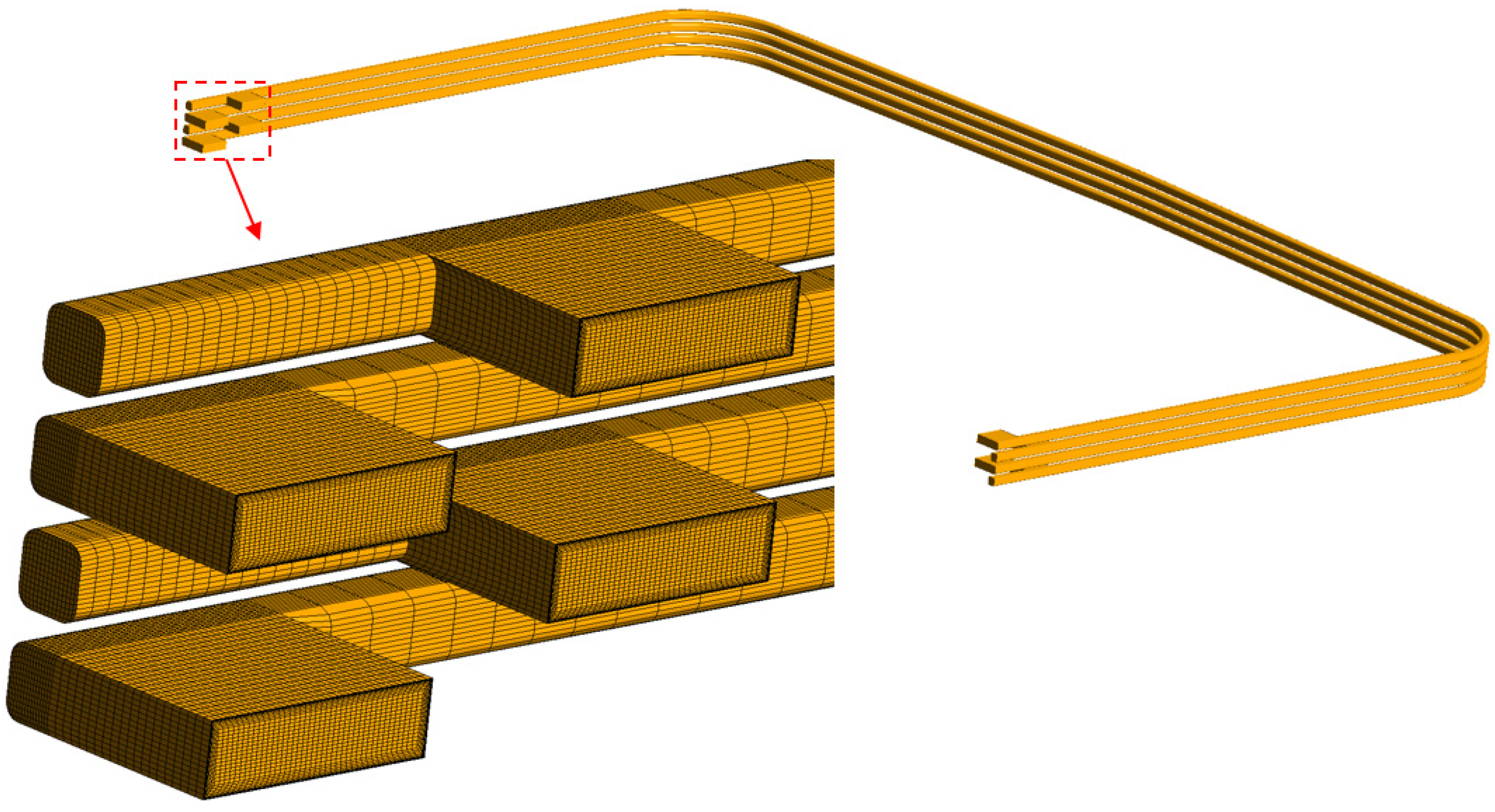
Figure 17.
Mesh of pin fluid domain of COB unit slice.
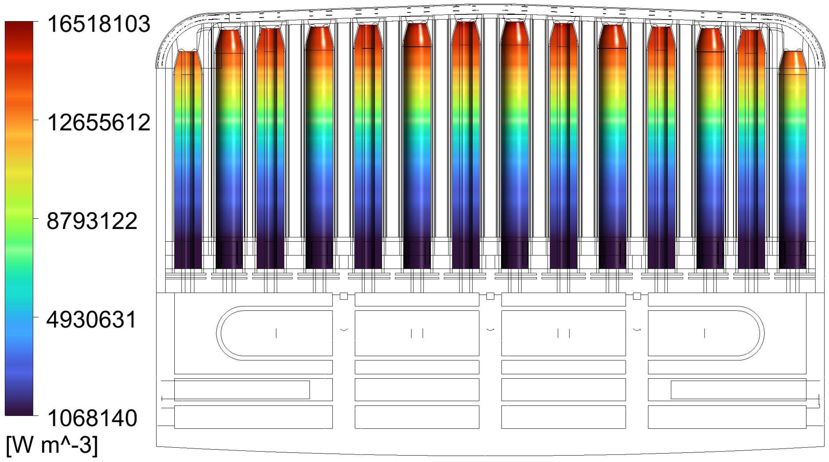
The nuclear power density of different materials were calculated by MCNP5-1.60. The power densities are 1-D profiles, as function of radial position. The mapping of the power density of ACB pebble bed is shown in Figure 18.
Figure 18.
Nuclear power density mapped on the ACB bodies.
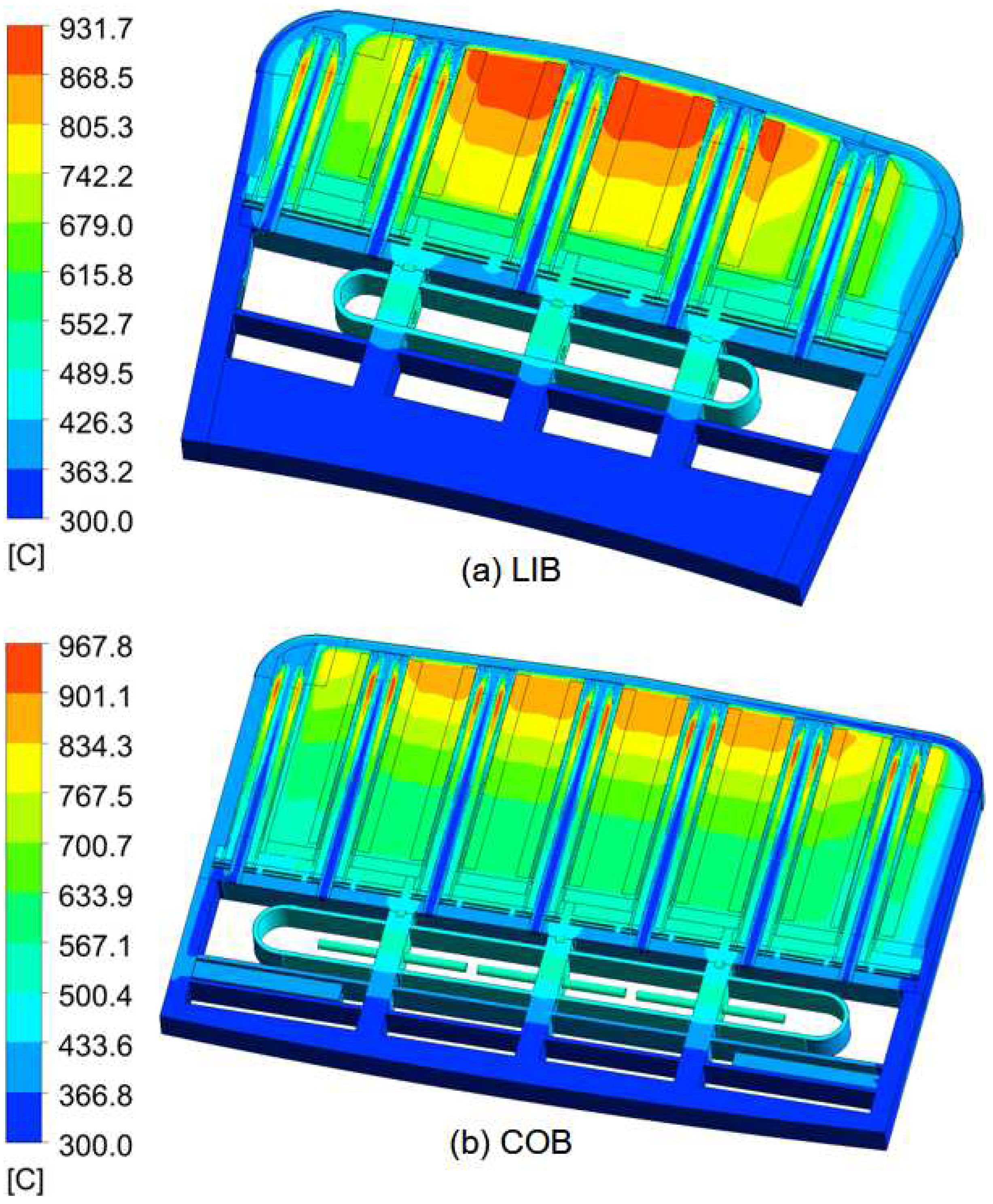
After several iterations, the temperatures of different materials met their corresponding limits. The temperature contours of LIB and COB unit slices are shown in Figure 19. The average temperature of ACB and TiBe12 are 637 °C and 769 °C for LIB; 615 °C and 685 °C for COB, respectively.
Figure 19.
Temperature field of LIB and COB unit slice at equatorial region.
The streamlines of the velocity of LIB and COB unit slices are shown in Figure 20 and Figure 21. It is observed that at the pin outlets the velocity increases due to the decrease of the flow channel. This can lead to high pressure drop, as shown below.
Figure 20.
Streamline of velocity in the pins of LIB unit slice.
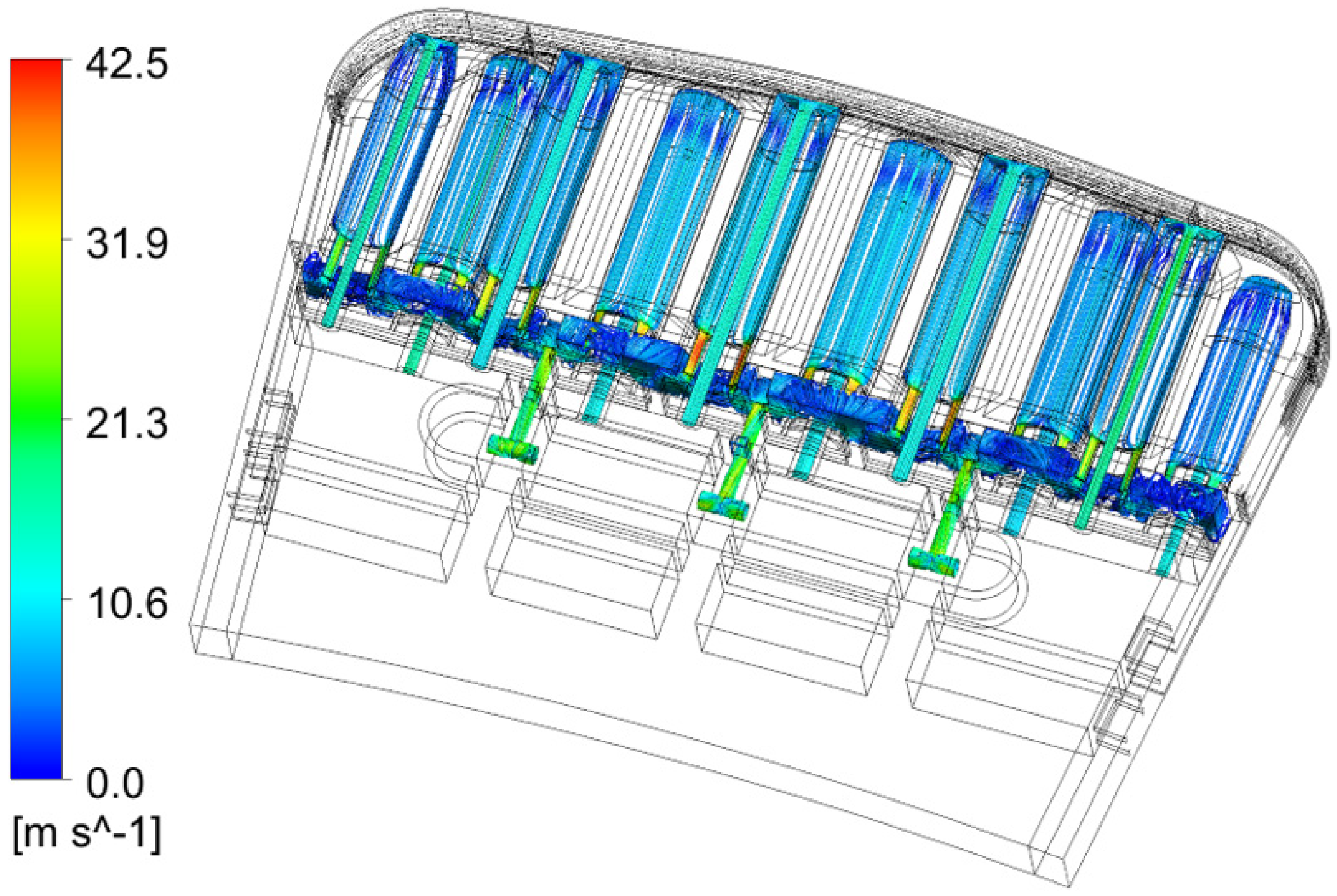
Figure 21.
Streamline of velocity in the pins of COB unit slice.
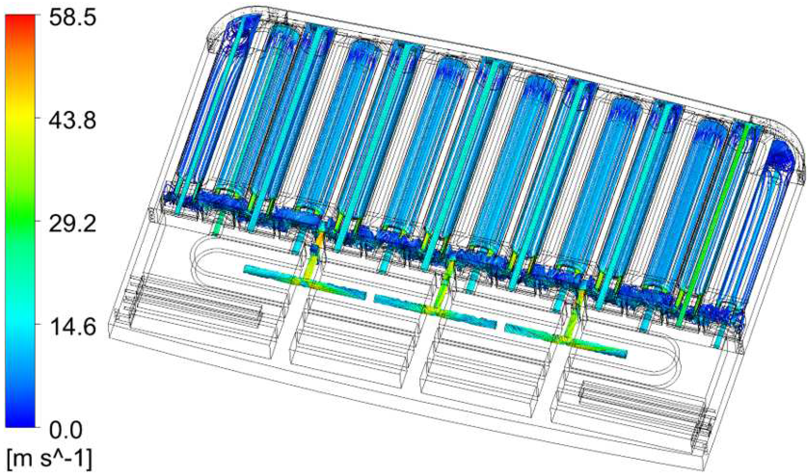
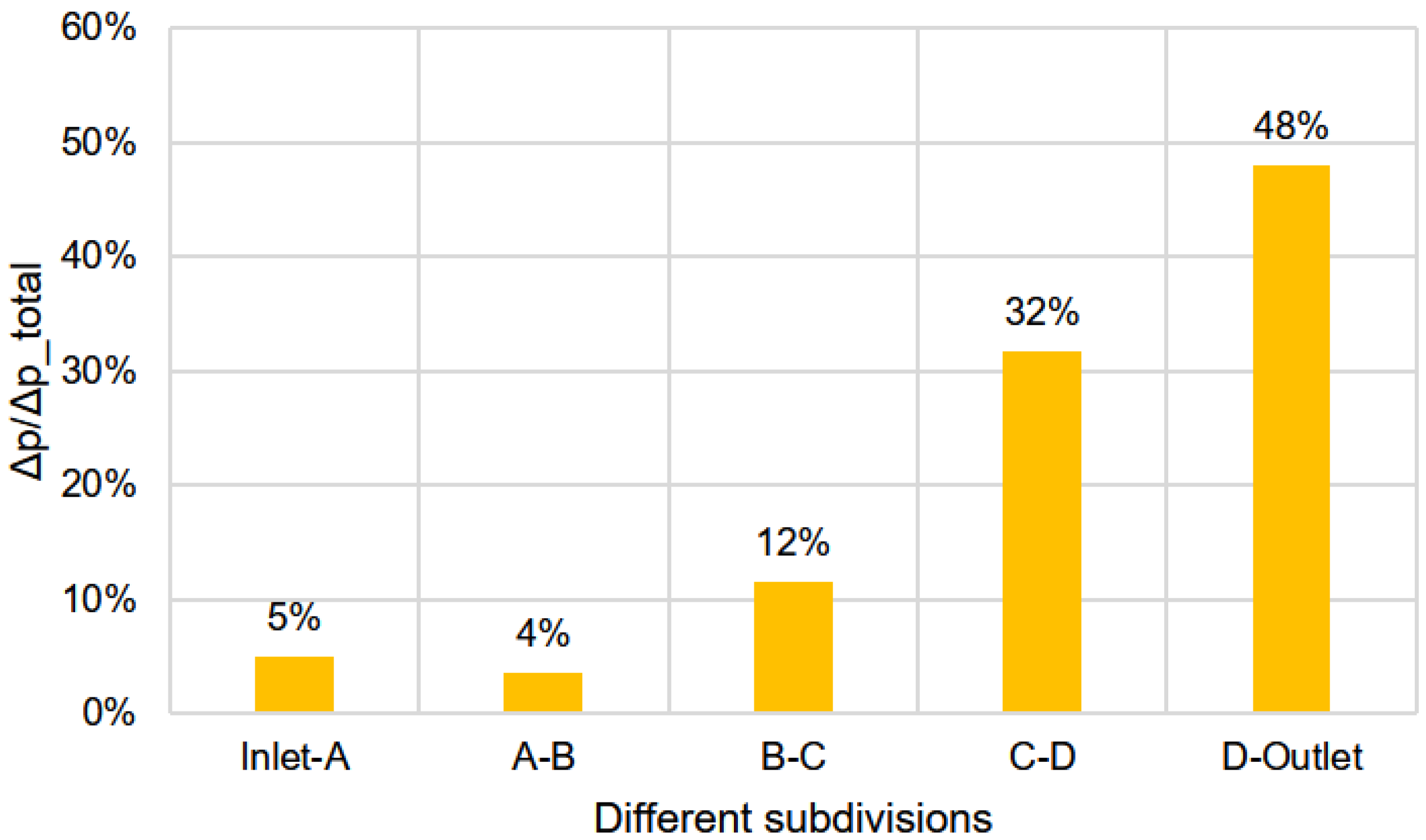
The total pressure drop in one pin of COB is about 0.16 bar. The subdivisions and percentage of pressure drop in one pin are shown in Figure 22 and Figure 23, respectively. It is observed that the largest contribution of pressure drop is caused by the abrupt changes of local cross-section. Optimization of detail geometry will be investigated at next stage.
Figure 22.
Coolant pressure drop subdivision in the pin of COB unit slice.
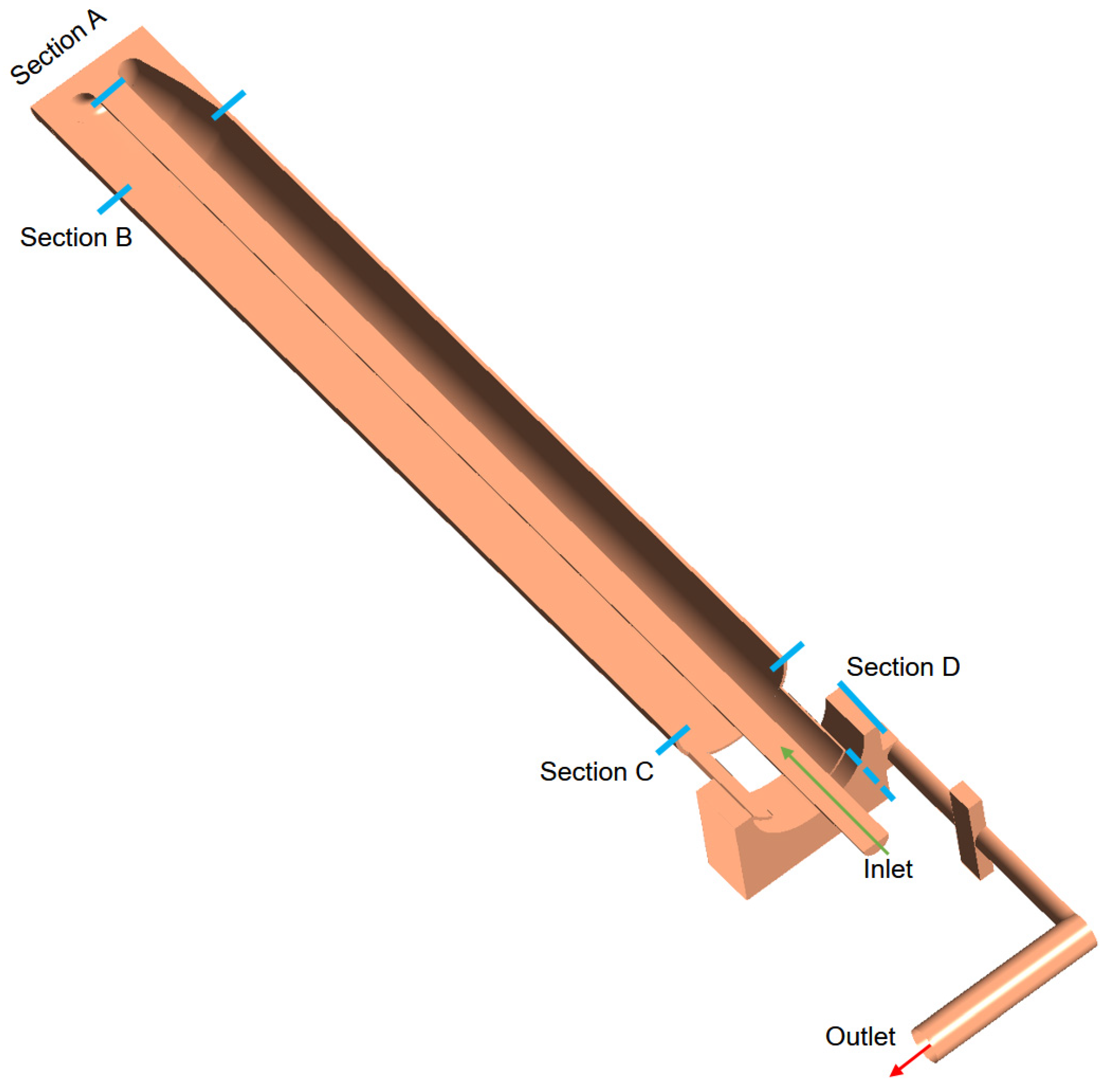
Figure 23.
Pressure drop percentage of different subdivision in the pin of COB unit slice.
3.3. Thermal mechanical analyses
3.3.1. Elastic analyses on a detailed unit slice
The thermal mechanical (TM) assessments were done based on a unit slice of the COB for in-box loss of coolant accident (LOCA) scenario and normal operation (NO) at the flattop. The thermal mechanical analyses were conducted using the Finite Element Method (FEM) software ANSYS. As the shape of cladding in the pin does not affect the structural integrity of the blanket box, the FEM model is still based on the funnel shape version of HCPB BB. The FEM mesh was mostly made with hexagonal elements, shown in Figure 24. The element order is quadratic, and at least 2 elements are ensured through the thickness of FW and fuel-breeder pin wall. Totally, there are 1.35 million elements and about 5 million nodes. The boundary conditions, shown in Figure 25, are: symmetry boundary condition in the poloidal direction on one side and coupled displacement of the nodes on the other side, allowed to move only in a plane. Two edges on BSS are fixed. Regarding the nodes on the top surface of the model, coupling have been used: tilting plane coupling (generalized plane strain condition).
Figure 24.
FEM mesh for thermal mechanical analyses of COB unit slice.
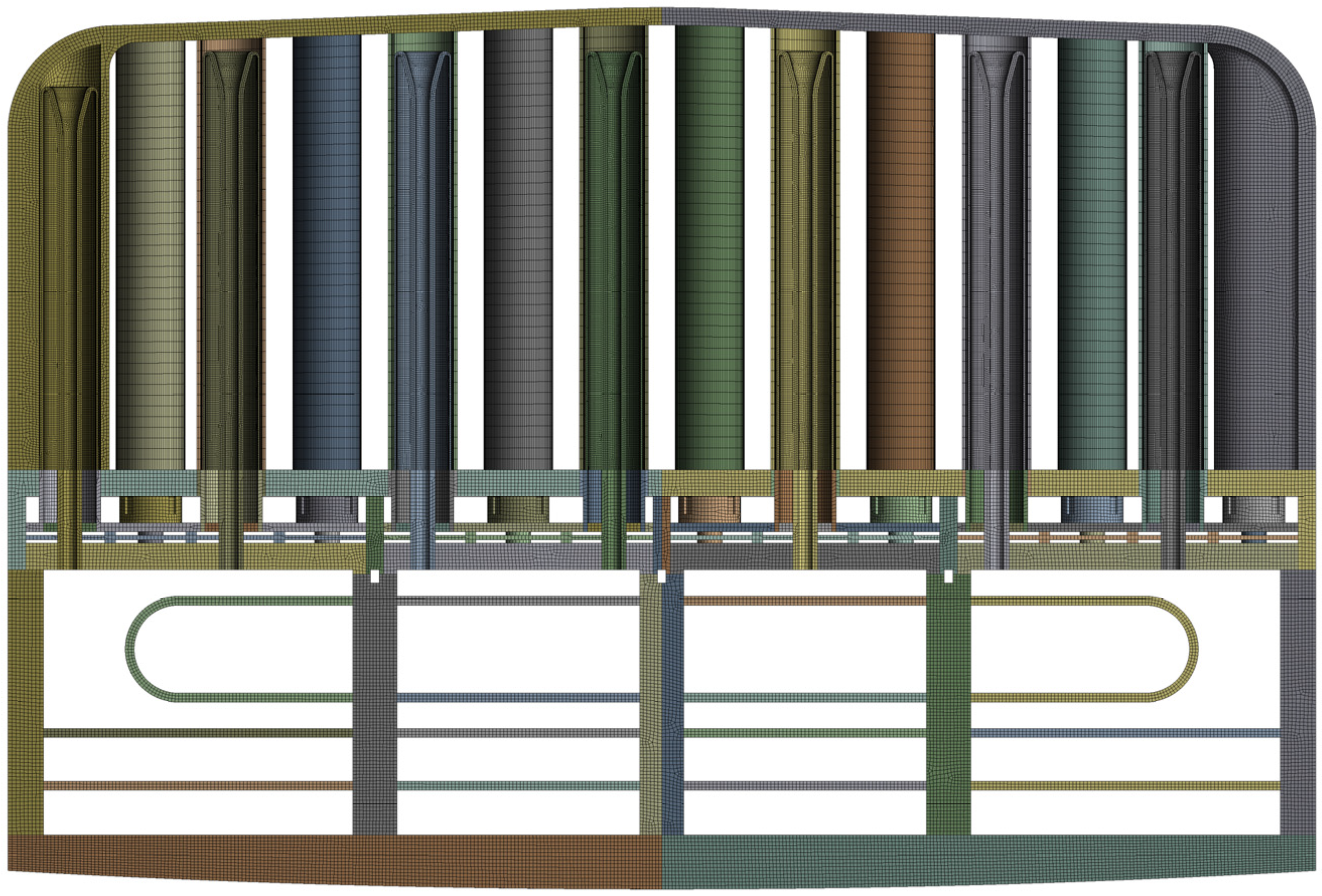
Figure 25.
Boundary conditions for TM analyses .

Here, two types of loads were considered: primary load (pressure) and secondary load (temperature field). As a first step only the primary stresses are assessed. The blanket box is pressurized with 10 MPa (8 MPa normal pressure + uncertainties), applied on the surfaces in contact with coolant and the purge gas. Thereafter, both 10 MPa and temperature field are applied. The Primary stresses and Primary + Secondary stresses contour and related stress assessment regions are shown in Figure 26 and Figure 27 respectively. The detailed paths located at FW (regions A, B and D) are chosen as displayed in Figure 26 left.
Figure 26.
Primary stresses under In-box LOCA conditions [MPa].
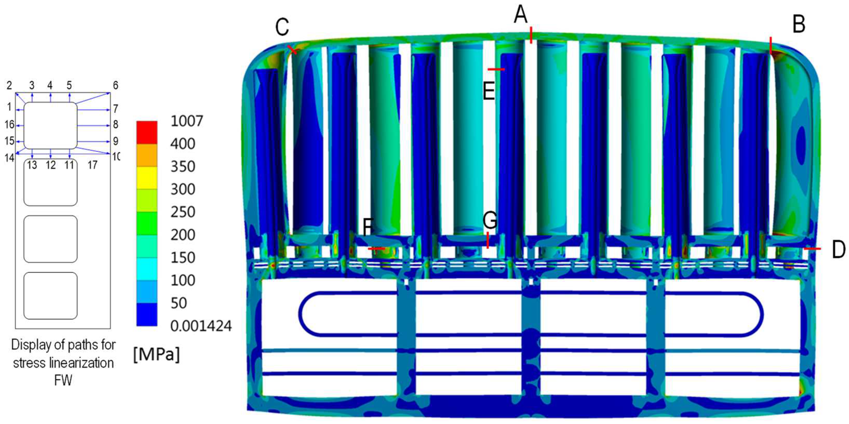
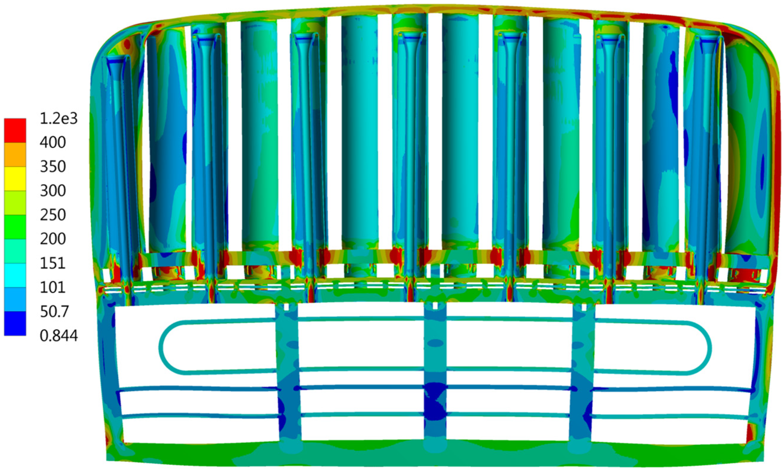
Figure 27.
Primary + Secondary stresses under In-box LOCA conditions [MPa].
According to the RCC-MRx rules [44], the immediate plastic instability (IPI), time-dependent fracture and immediate plastic flow localization (IPFL) are be assessed. At this stage, IPI and IPFL have been assessed. The temperature field has been taken from the thermal hydraulic analysis. A parameter Φ is defined as
Φ = (Stress Limit – Linearized Stress Value) / Stress Limit * 100%
The stress linearization according to the RCC-MRx rules are done. Here, only the paths at the location A are shown in Table 6.
Table 6.
Assessment of stresses against IPI and IPFL damage modes at region A
| IPI | IPFL | ||||||
|---|---|---|---|---|---|---|---|
| Path | Path average temp. | Linearized stress value | Stress limit | Φ | Linearized stress value | Stress limit | Φ |
| A1 | 480.0 | 210.8 | 286.2 | 50.9% | 321.0 | 455.0 | 29% |
| A2 | 480.8 | 205.3 | 285.7 | 52.1% | 317.8 | 453.1 | 30% |
| A3 | 476.3 | 200.2 | 288.3 | 53.7% | 329.8 | 463.8 | 29% |
| A4 | 448.0 | 221.8 | 304.8 | 51.5% | 384.0 | 529.9 | 28% |
| A5 | 431.6 | 215.9 | 312.6 | 53.9% | 400.6 | 559.4 | 28% |
| A6 | 431.7 | 230.6 | 312.5 | 50.8% | 363.7 | 559.2 | 35% |
| A7 | 455.8 | 217.7 | 300.4 | 51.7% | 366.3 | 512.5 | 29% |
| A8 | 456.7 | 221.6 | 299.9 | 50.7% | 361.1 | 510.3 | 29% |
| A9 | 457.3 | 216.7 | 299.5 | 51.8% | 358.5 | 508.9 | 30% |
| A10 | 458.2 | 212.5 | 299.0 | 52.6% | 353.6 | 506.8 | 30% |
| A11 | 459.5 | 214.8 | 298.2 | 52.0% | 377.1 | 503.7 | 25% |
| A12 | 438.1 | 212.6 | 309.5 | 54.2% | 374.9 | 547.7 | 32% |
| A13 | 437.3 | 212.8 | 309.8 | 54.2% | 312.4 | 549.1 | 43% |
| A14 | 451.9 | 200.1 | 302.7 | 55.9% | 304.5 | 521.7 | 42% |
| A15 | 479.4 | 206.9 | 286.5 | 51.9% | 318.7 | 456.4 | 30% |
| A16 | 481.5 | 213.6 | 285.3 | 50.1% | 315.2 | 451.4 | 30% |
| A17 | 456.9 | 216.4 | 299.7 | 51.9% | 339.6 | 509.9 | 33% |
It was found that the stresses at regions A, B and E have fulfilled the damage modes of IPI and IPFL. At region C, the stresses fulfil the IPFL limits and stresses at a few paths are slightly higher than the IPI limits. This is due to the bending at the side wall. At regions F and G, the structure fails to fulfil the IPFL limits. At the regions F and G, the temperature is high due to their vicinity to the coolant outlet. Reducing the temperature at these regions will reduce the thermal stresses there. The IPFL limits were considered too conservative [45]. In the future, the design should be assessed and optimised with consolidated Eurofer97 material data.
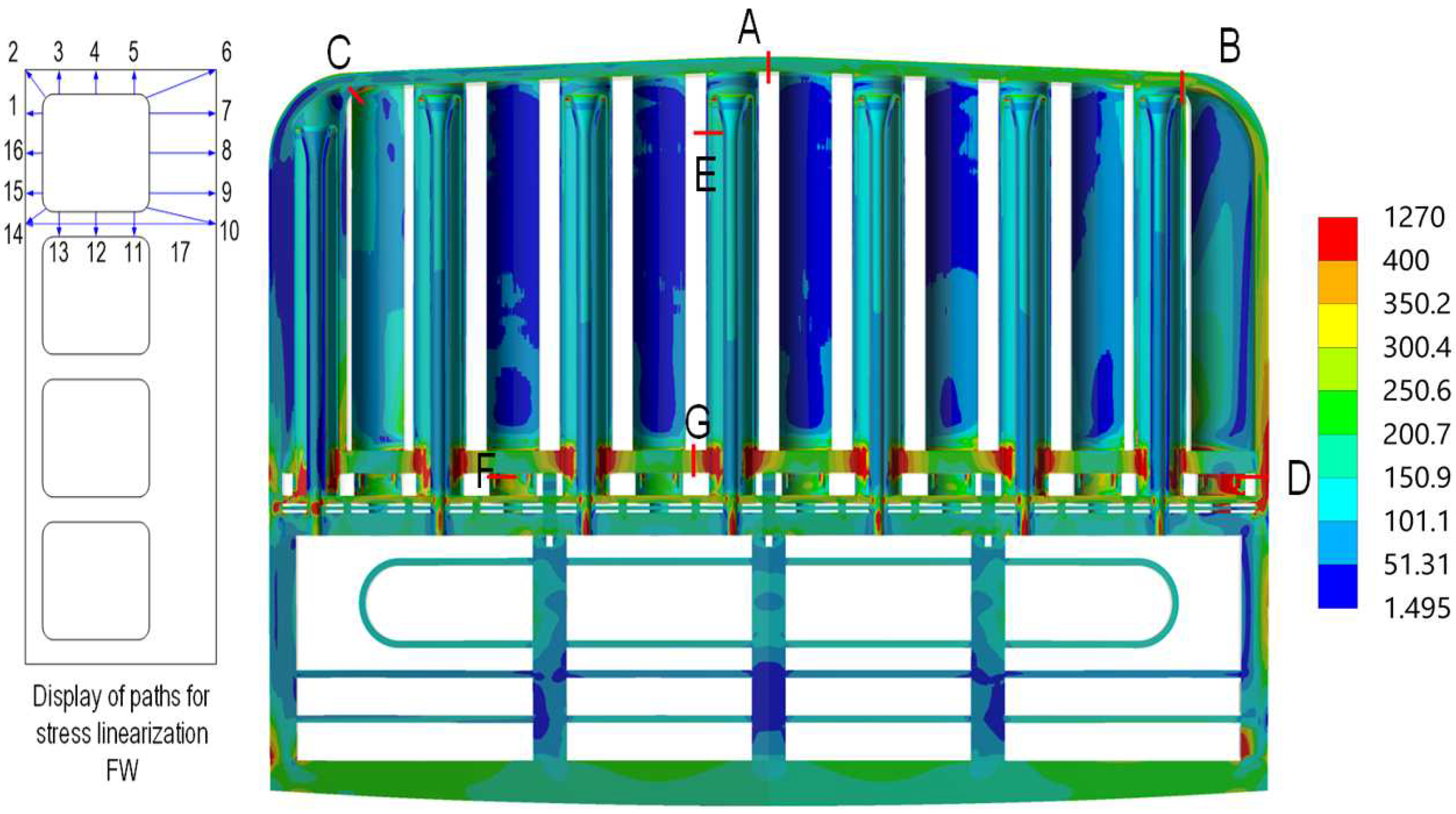
The FEM model and boundary conditions of the TM analysis under normal condition is similar with the one that was used for the In-box LOCA analysis. The loads consisted of thermal and pressure loads and deadweight. All the surfaces contacting helium coolant have 8 MPa and all the surfaces contacting purge gas have 0.2 MPa gas pressure. The contour and critical paths of Primary + Secondary stresses under normal condition are shown in Figure 28.
Figure 28.
Primary + Secondary stresses under normal condition [MPa].
The damage modes of Immediate Plastic Collapse (IPC), Immediate Plastic Instability (IPI), Immediate Plastic Flow Localization (IPFL), Creep Differed Excessive Deformation (CDED) and Rupture (CDR) (negligible irradiation), Progressive Deformation (negligible creep and irradiation) and Fatigue should be assessed at Criteria Level A. All these damage modes have been assessed with the exception of the Creep Differed Rupture, which will be added in the near future.
For the Progressive Deformation (Ratcheting) and Fatigue damage modes assessment, the maximal range of total stress intensities should be calculated. In this case, the range of total stress intensities at the temperature fields at the flattop period (temperature at the maximum) and at the cold state (before blanket start-up) was considered as the maximal range of total stress intensities.
It was found that most of the critical regions fulfilled the design criteria for selected damage modes. The region connecting breeder zone and the backplate (at Path D and alike) failed to fulfil the design criteria against the IPFL and ratcheting damage modes. This is due to the large temperature difference between the breeder zone (hot) and backplate (cold). Possible solutions to solve this problem are to increase the thickness of the connecting regions and/or homogenize the temperature between the two parts. Due to the lack of fusion-relevant irradiated Eurofer97 data, the stress allowables are not consolidated. The stress limits of IPFL and ratcheting damage modes were also considered too conservative [45]; nevertheless, most of the selected regions fulfil this criterion.
3.3.2. Inelastic analyses on the cap region of HCPB BB
As noted by the European fusion community that the elastic route of assessing the structural integrity of the blanket is too conservative [45], the first attempt to use inelastic route to reduce the conservatism on blanket was done in [46]. The inelastic analyses were compared to the elastic analyses of the HCPB blanket under in-box LOCA scenario. Two dominant damage modes were considered relevant: exhaustion of ductility and plastic flow localization. Compared to the overly conservative elastic route, the inelastic route allows to reduce the conservatism in the design of blanket.
3.3.3. Global elastic analyses of blanket segment
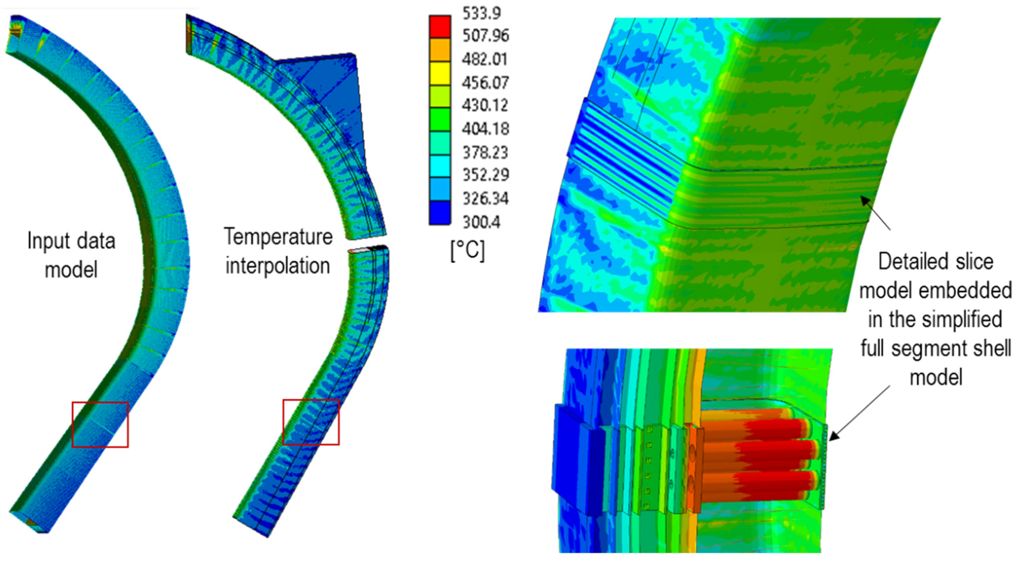
A simplified finite element method (FEM) model of the HCPB-BL2017 central outboard (COB) segment has been created to perform elastic analyses. The geometry has been simplified to meet the main objectives of the project, which are to perform a global analysis of the sector’s mechanical behavior based on the SMS segmentation. The internal distribution of the pipes and some BSS plates have been reconstructed using the detailed geometry of a COB slice. The FEM representation of the detailed slice of the COB segment has been generated from the detailed slice of the COB11 and embedded in the global segment model. The detailed slice CAD model is 62.5 mm in height, and this geometry has been extended using symmetry operations such that the final detailed geometry covers a total height of 375 mm (six repetitions of 62.5 mm).
To join the detailed COB11 unit-slice at the equatorial region of the COB segment, some elements of the global model have been removed in that region, and the boundary nodes/elements have been translated to form a straight boundary. The detailed COB11 slice model thus matches perfectly with the boundaries of the global model. The deformation of the global model is then considered to be transferred to the detailed slice model.
To reduce the number of nodes in the model, the FW with internal channels has been simplified using an orthotropic equivalent shell section, which has been verified for some representative scenarios with static, dynamic, and thermal loads. The simplified methodology has provided satisfactory results compared to a reference detailed solid model in terms of global behavior. However, local stresses and displacements through the thickness cannot be captured by this simplified methodology, but this was not the objective of this methodology.
Electromagnetic (EM) and thermal loads were applied to the segments. The application of the input loads onto the mechanical mesh involves some intermediate steps to adapt those inputs to the mechanical mesh generated. Interpolated temperature profiles have been mapped onto different elements of the segments, as shown in Figure 29.
Figure 29.
Temperature reconstruction on the different segments.
The latest data in [47] has been used for the EM loads, which are then interpolated onto the mechanical mesh. For this study, EM loads at two different time steps (11.52 s and 11.594 s) were provided from EM experts and a static analysis was conducted on the five segments. At this stage no construction site of European DEMO was chosen, therefore dynamic amplification effects were not considered in this analysis. These time steps were chosen as they corresponded to the instants when the global resultant forces and moments peaked. Although other time steps might result in a more severe combination of loads, a more detailed analysis is not currently necessary.
The thermo-mechanical analysis showed similar stress patterns in all segments at both time instants. The following discussion focuses on the COB segment at 11.52 s, but a similar analysis can be conducted for the other segments. The analysis assumed full contact between the segments and the VV supports at the end of the ramp-up, with EM loads applied at this state. Achieving this ideal configuration (fully supported segments with minimal thermal stress) may be challenging, and the design of the supports needs to be carefully considered. Additionally, the segments may need to be assessed under seismic loads while not fully supported, but this is outside the scope of this work.
The von Mises stress distribution in the COB11 slice after applying thermal and EM loads separately is shown in Figure 30. One important outcome of the analysis is that stresses due to EM loads are significantly smaller than those caused by thermal loads. Therefore, thermal loads are the main driver of the design and may require rethinking of the strategy for reducing them by design in the next stage of DEMO development. Figure 31 illustrates the von Mises stress distribution of the COB11 and highlights the most heavily loaded areas.
Figure 30.
Von Mises stress contour plot on the COB at 11.52 s [Pa].
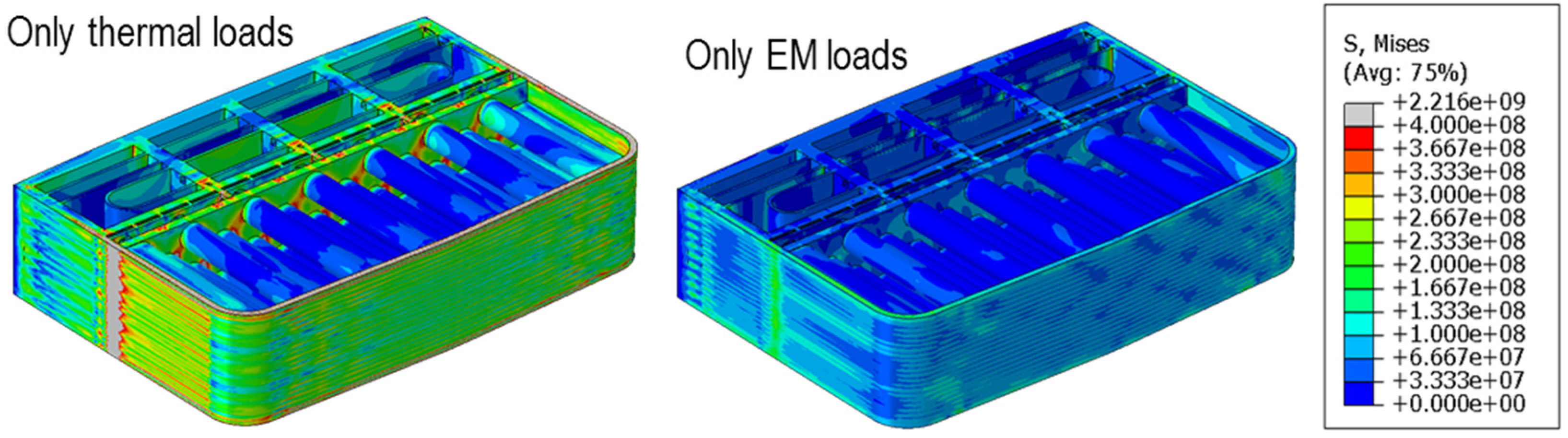
Figure 31.
Von Mises stress contour plot and some details of the most loaded regions [Pa].
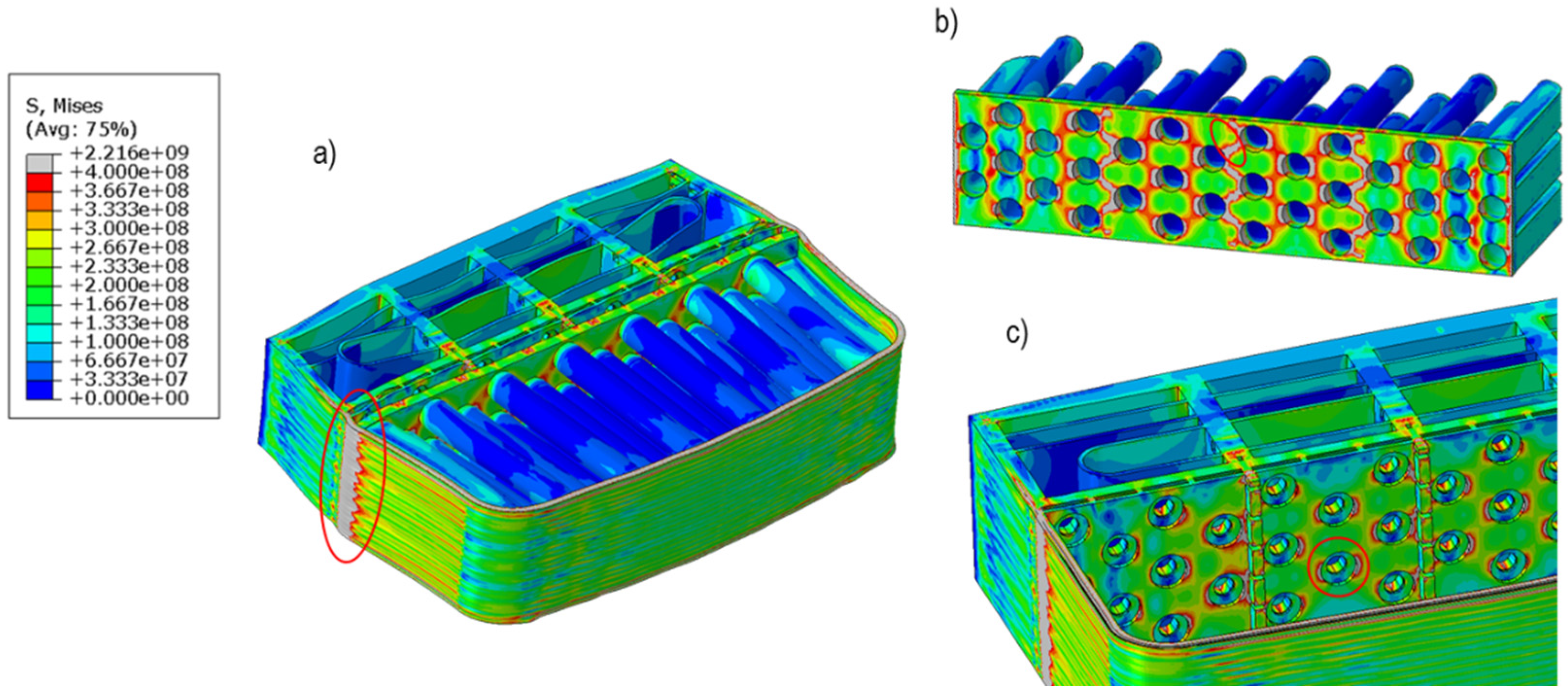
The lateral pins connected to the FW and BP1 (BZ back-plate) experience the highest stresses, primarily due to constrained thermal expansion and large thermal gradients in these components. RCC-MRx code was used to assess the components for the IPFL mode in the analysis of thermal loads only, and for the IPC, IPI, and IPFL modes in the thermal and EM loads analysis. Our findings indicate that margins for the IPFL in the NO case are lower than those for the Vertical Displacement Event (VDE) case. This is because the allowables for an accidental scenario are significantly higher than those for the NO scenario. Additionally, the EM loads are not high, which contributes to larger margins during the VDE-up accidental scenario.
Although boundary conditions based on generalized plane strains, generalized strain strains, symmetries, and similar techniques (as used in the analyses in Sub-sections 3.3.1 and 3.3.2) are appropriate given the preliminary nature of the current DEMO programme, we observed that they do not accurately capture the displacements globally. The simplified global model developed for this study acts as a proxy to provide the detailed COB11 slice model with appropriate boundary conditions. This or a similar methodology will be necessary for future detailed analyses of the BB.
A key recommendation resulting from this analysis is to maintain the BZ backplate at a lower temperature to reduce thermal stress in the BB, which has now become a key design driver. One way to achieve this is by reconfigure the manifolds so that the BZ backplate is exposed to "fresh" helium.
3.3.4. First thermal mechanical analyses of a single beryllide block
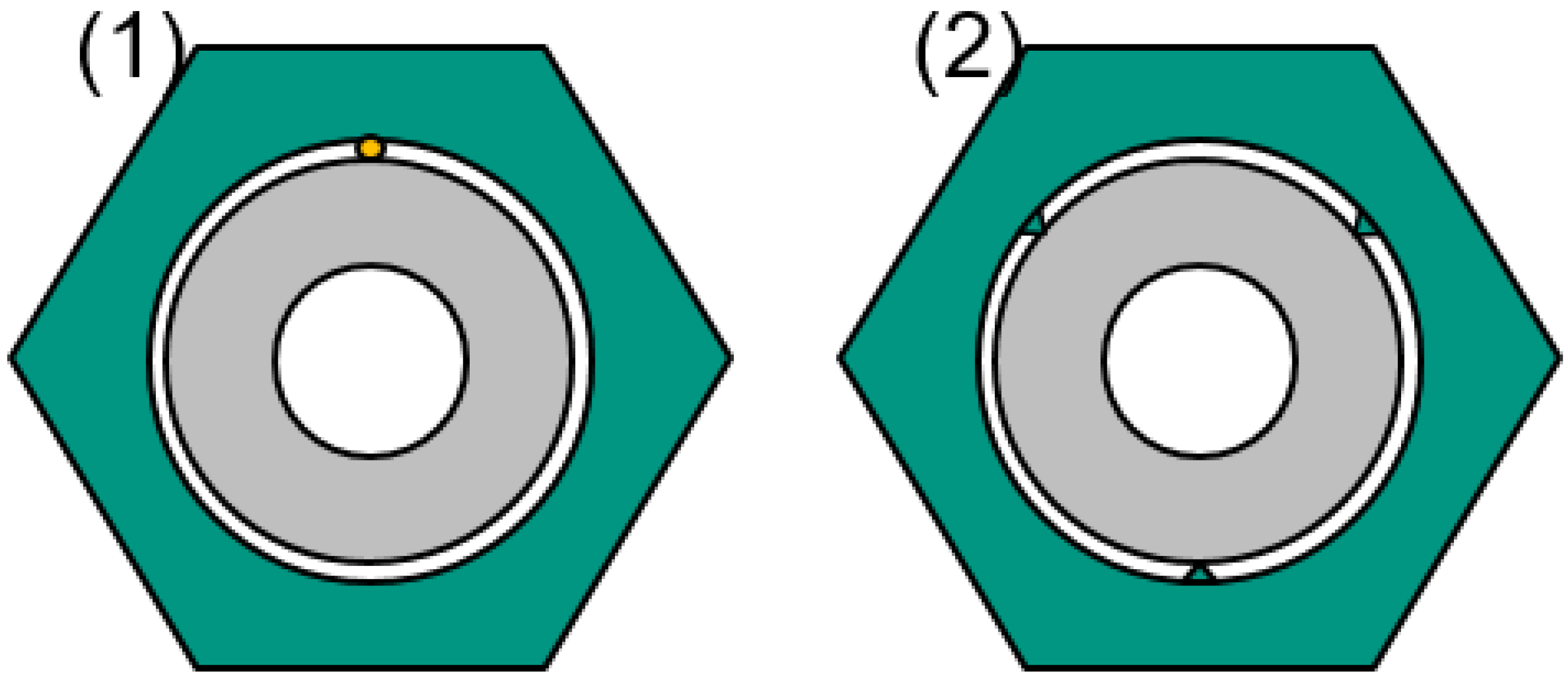
A scoping analysis was conducted to examine the stress state of a TiBe12 block under normal operating conditions with different boundary conditions. The beryllide blocks are designed to maintain a 1 mm gap from their pressure tube position during assembly, with the assumption that a spacer will ensure the required gap. Two spacer design options are proposed: (1) using helical wires with a diameter of 1 mm made of tungsten, zircaloy, SiC, or other high-temperature materials, and (2) directly shaping the inner hole of the block with a spacer shape through wire cutting, as shown in Figure 32.
Figure 32.
Spacer options between beryllide blocks and pressure tubes.
An initial assessment was performed to determine the ability of the spacer options under consideration to withstand the thermal loads on the pressure tubes and beryllide blocks. The first step involved estimating a worst-case interference value due to the difference in thermal expansion between the tube and block. The minimum radial expansion of the block’s inner radius at its lowest temperature during normal operation (450 °C) was calculated to be 0.270 mm, while the maximum thermal expansion of the pressure tube’s outer radius at its maximum temperature (600 °C) was calculated to be 0.295 mm. As a result, a worst-case interference of 0.025 mm was estimated.
In the next step, an interference pressure was calculated for these worst-case interference values between the pressure tube and the block, using analytical equations for thick cylinders subjected to pressure. It was assumed that the cylindrical surfaces of the block and tube were in direct contact, and the spacers and their thermal expansion were not considered in the calculations. Based on these assumptions, the contact pressure developed at the mating surfaces was estimated to be approximately 5 MPa. To arrive at a design load, a factor of safety of 3 was applied to this load, resulting in a design load of 15 MPa.
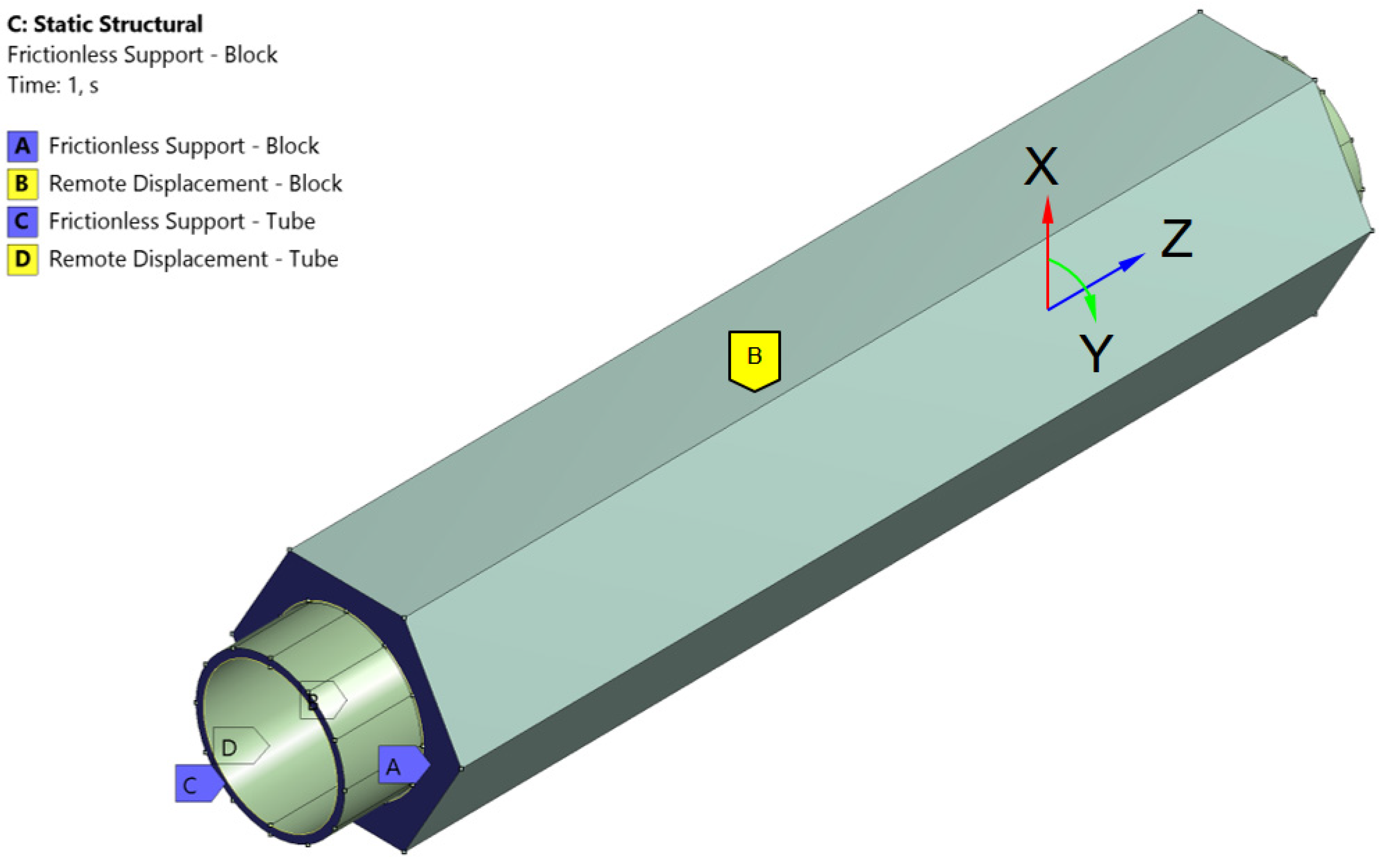
Thermo-structural simulations were conducted on both the block and the tube to investigate their behavior under calculated design interference pressure and temperature. The simulation process involved two stages. Firstly, a thermal load was applied to simulate normal operational conditions, followed by the application of pressure load corresponding to each design option. The pressure load was applied as a line pressure on the proposed contact surfaces, as illustrated in Figure 33 and Figure 34. Figure 35 presents the boundary conditions used in the simulations. The boundary conditions of A and C are on the bottom surfaces of the Tube and Block, the boundary conditions of B and D are on the body of Tube and Block respectively.
Figure 33.
Interference pressure load – option 1.
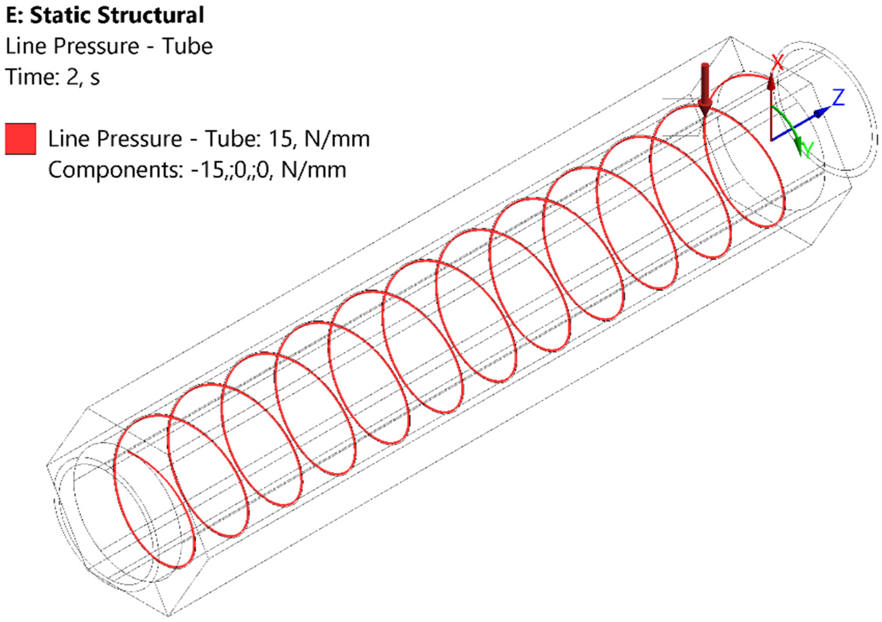
Figure 34.
Interference pressure load – option 2.
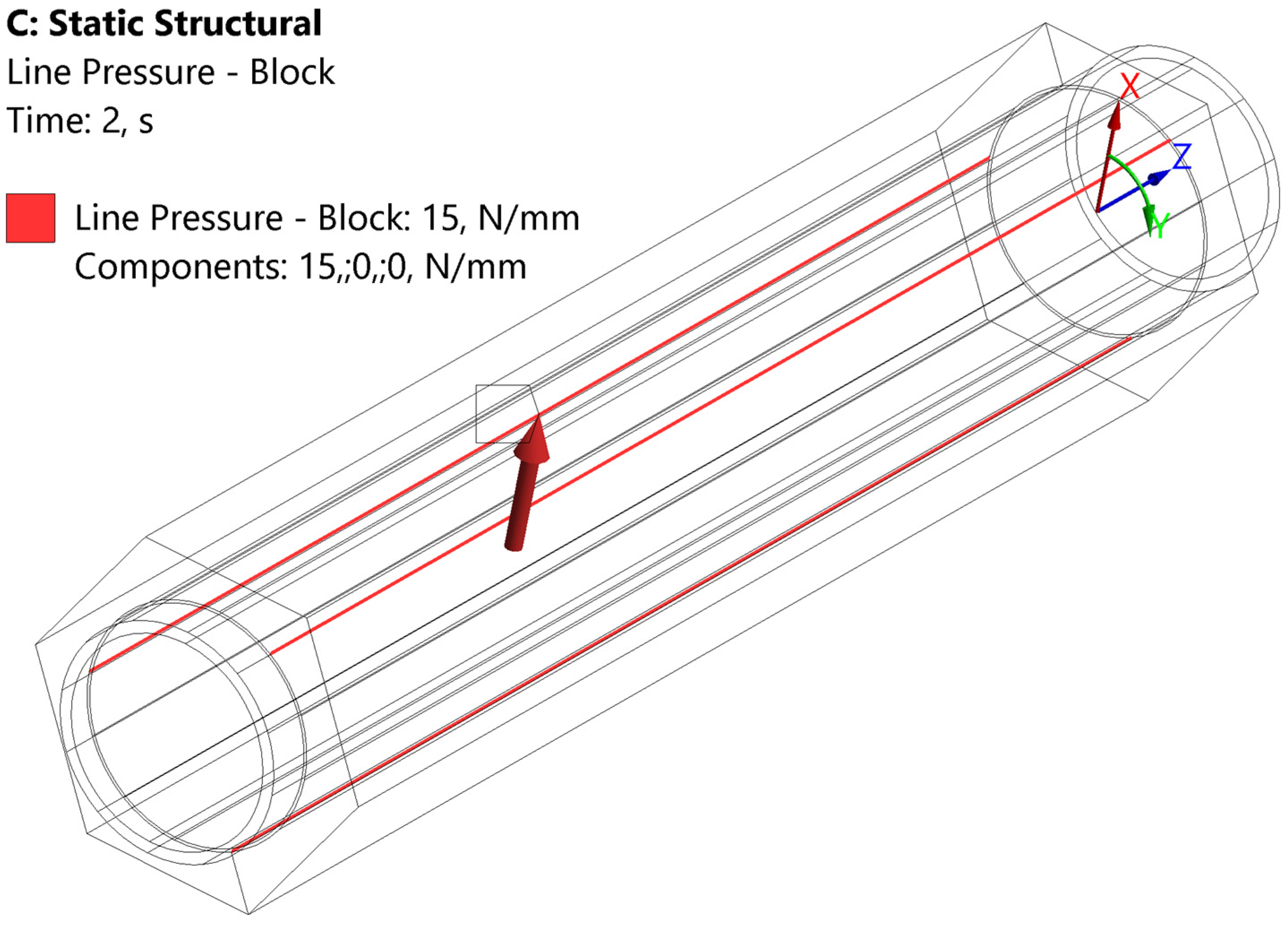
Figure 35.
Boundary conditions.
The radial displacement values are shown in Figure 36 and Figure 37. It can be observed that the pressure load causes a negligible deformation compared to the thermal deformation.
Figure 36.
Radial deformation - design option 1 (helical wire support).
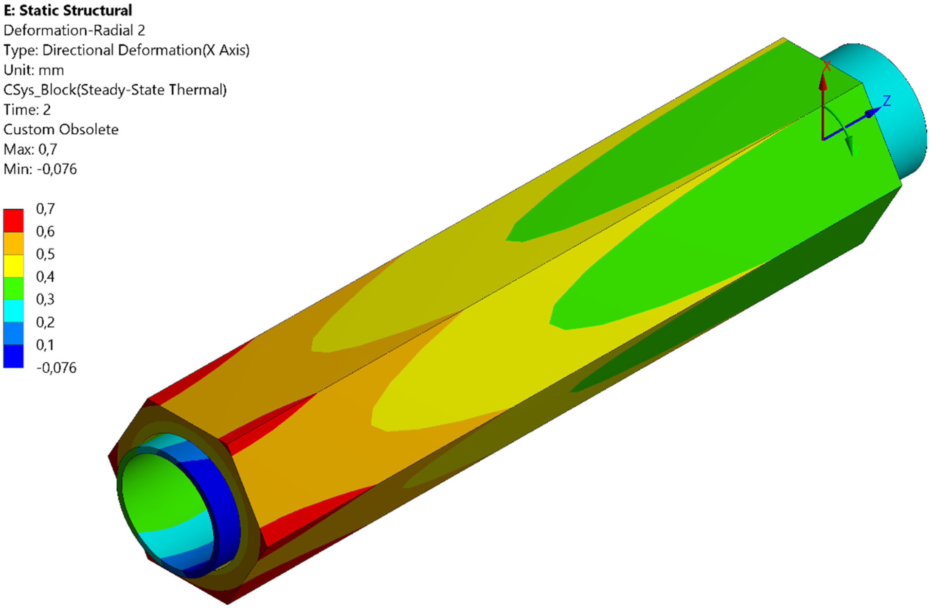
Figure 37.
Radial deformation - design option 2 (wire cut).
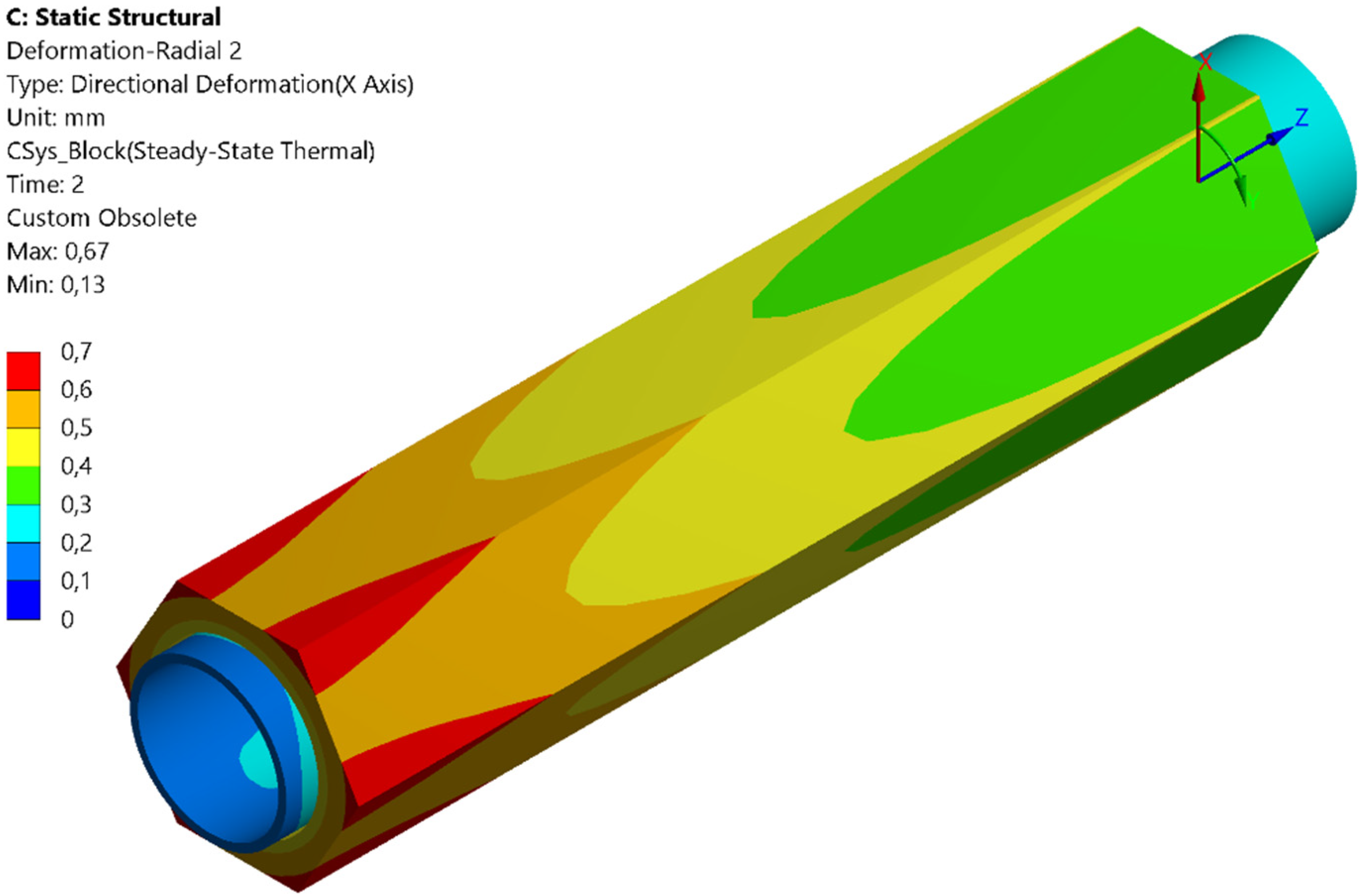
Figure 38 and Figure 39 show the von-Mises equivalent stress distribution for the first design option, while Figure 40 and Figure 41 show the stress distribution for the second design option. The maximum stress observed on the beryllide block is approximately 17 MPa for the first design option and 18 MPa for the second design option, which is significantly lower than the compressive stress limit of beryllide.
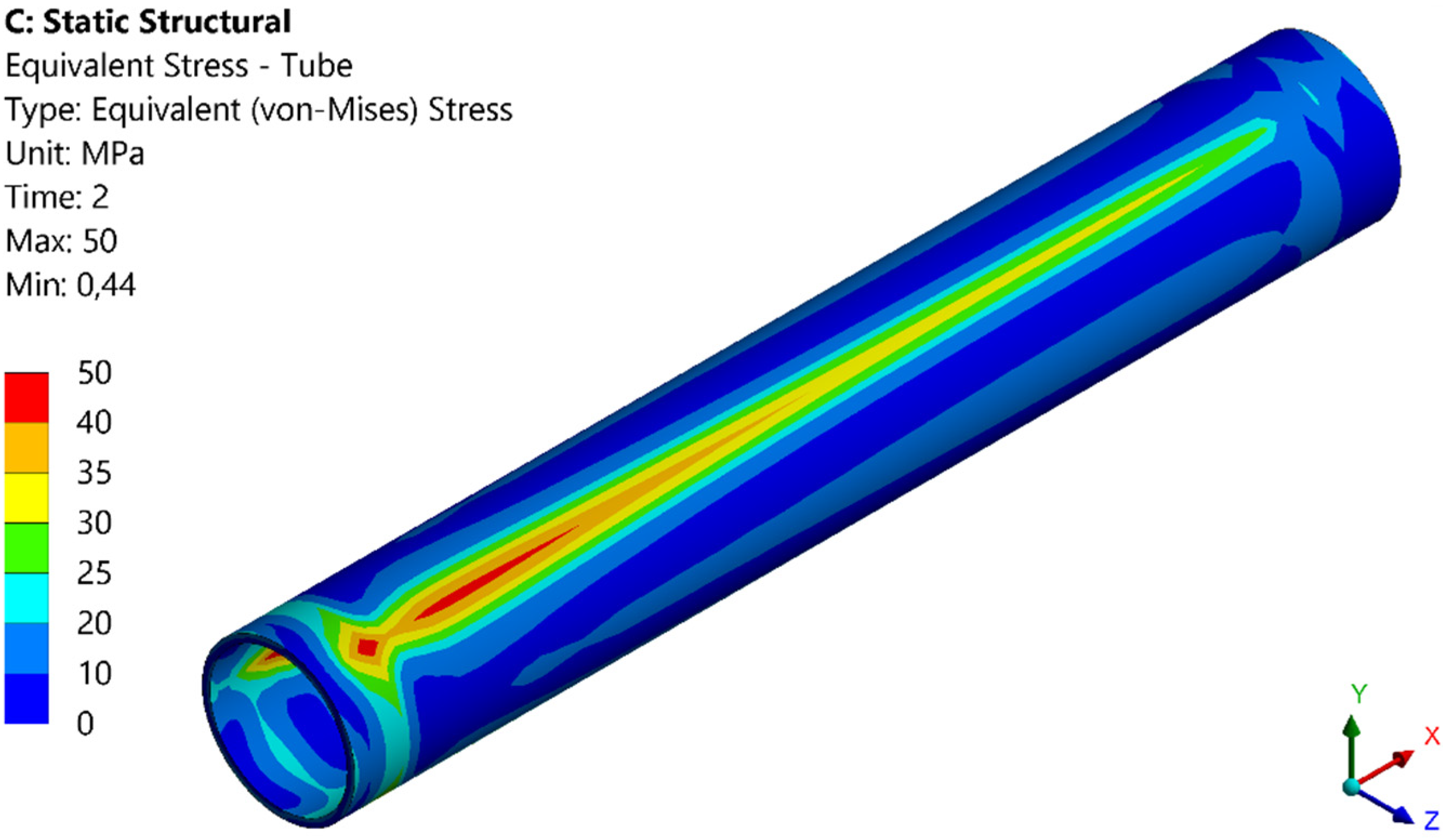
For the pressure tube, the peak stress is approximately 37 MPa in the first design option and 50 MPa in the second design option. However, given that the minimum yield stress of Eurofer97 exceeds 250 MPa in the relevant operating temperature range, we can conclude that the pressure tube is safe from yielding in both design options.
Figure 38.
Von-Mises stress distribution - beryllide block (design option 1).
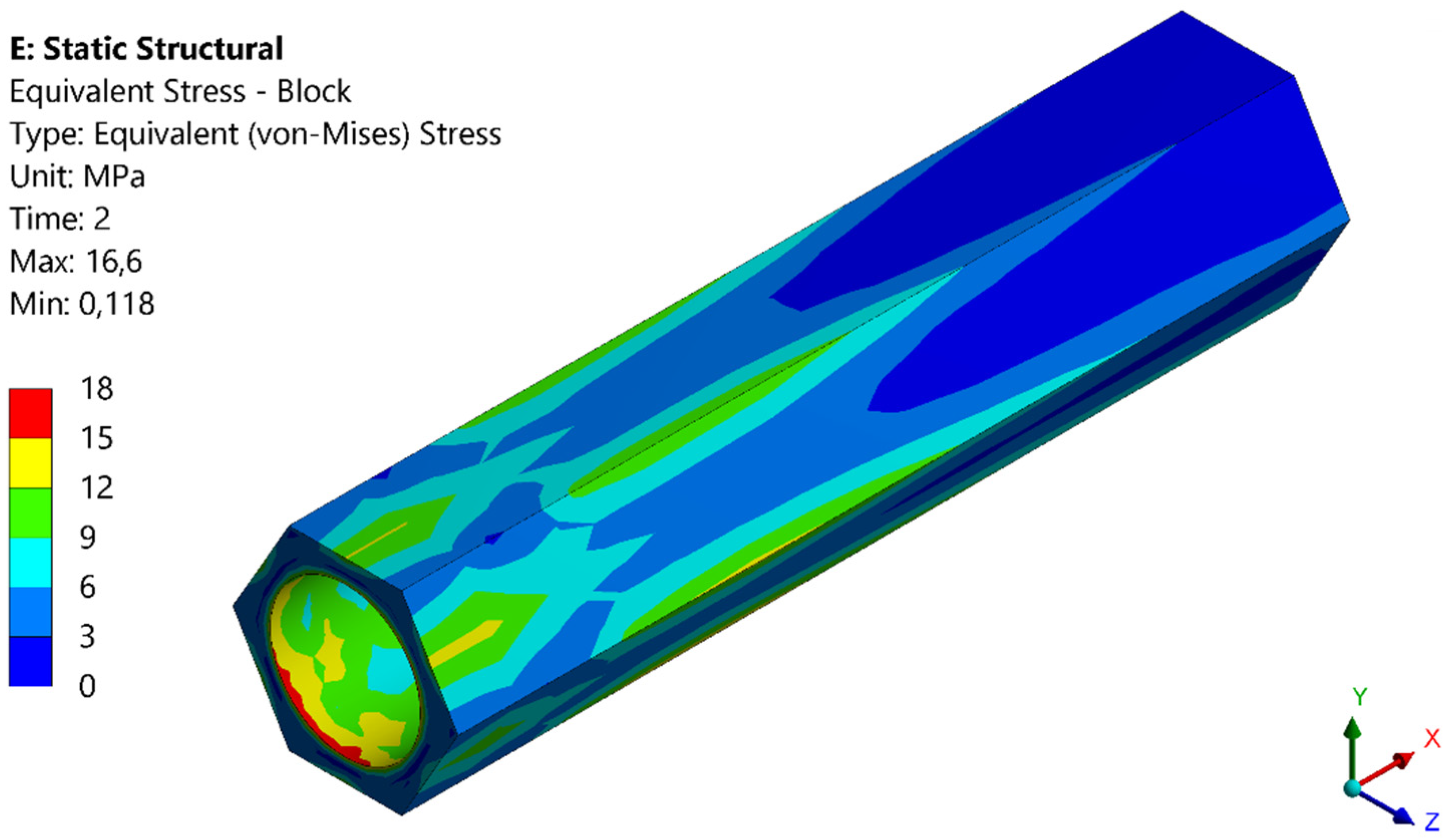
Figure 39.
Von-Mises stress distribution – pressure tube (design option 1).
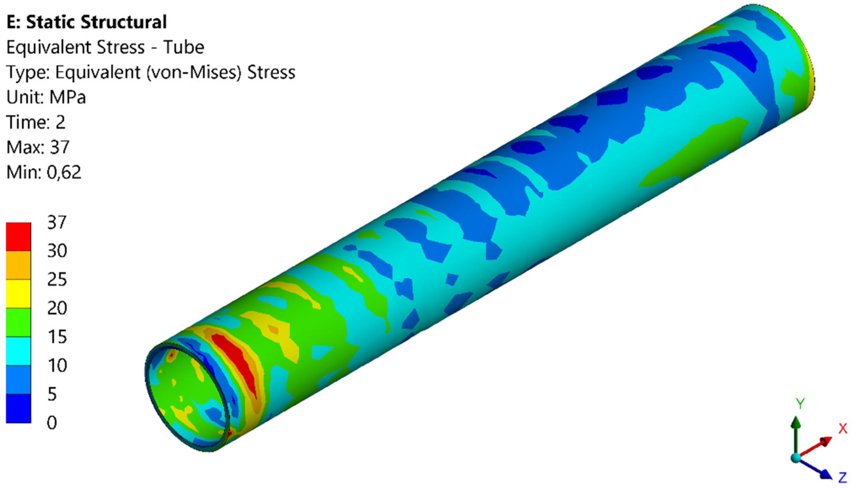
Figure 40.
Von-Mises stress distribution - beryllide block (design option 2).
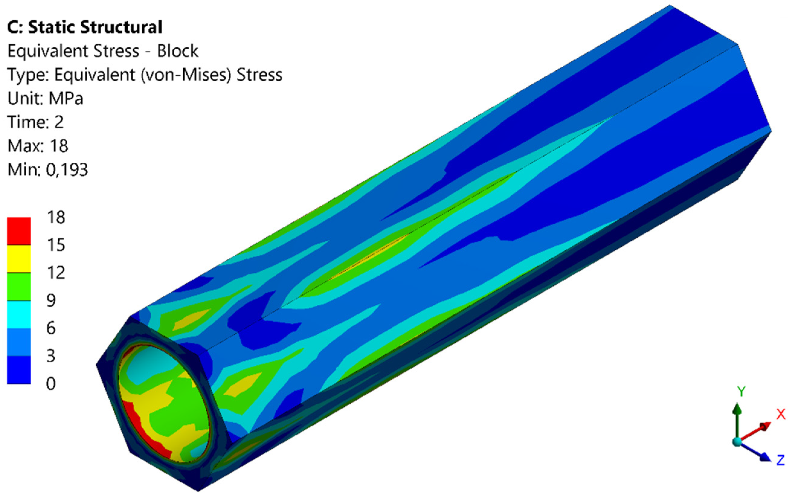
Figure 41.
Von-Mises stress distribution – pressure tube (design option 2).
3.4. Tritium transport analysis
During the PCD phase, tritium transport modelling was conducted both at the system level using EcoSimPro [48] and FUS-TPC [49], and at the component level [50], using OpenFoam. This modelling is continually updated to ensure confidence in the developed tools. To validate the tritium transport simulations, different experiment rigs were constructed and commissioned [51,52].
Recent tritium transport analysis at the fuel-breeder pin level for HCPB BB [50] indicates that the permeation of tritium into the coolant is influenced by the partial pressure of H2 added to the purge gas and the velocity of the purge gas. The results also demonstrate that adding a small fraction of steam (up to 300 Pa partial pressure) to the purge gas reduces the tritium permeation into the coolant due to the non-permeable nature of HTO.
4. Alternative breeding blanket concepts
In the PCD phase, various alternative BB concepts were explored. However, it should be noted that these studies were purely exploratory and do not serve as replacements for the established HCPB BB concept. In the event of any interest, these concepts may be considered for incorporation into the main work program.
4.1. CO2 Cooled Pebble Bed (CCPB) concept
With the growing interest in utilizing CO2 as a coolant in industrial applications and the availability of CO2-compatible turbomachinery, CO2 has emerged as an attractive alternative to Helium as a coolant. Table 7 presents the thermophysical properties of Helium and CO2 at 8 MPa and an average coolant temperature of 400 °C in the blanket. However, CO2 has a lower specific heat at constant pressure and thermal conductivity than Helium. To investigate the thermal efficiency of two breeding blankets using Helium and CO2 as coolants for the Primary Heat Transfer System (PHTS), a comparative study was conducted. The results showed that, with the same configuration, the net thermal efficiency of the breeding blanket using CO2 as a PHTS coolant is better than that of Helium [53]. Furthermore, due to CO2’s higher mass density at the same pressure and temperature, the circulating power can be reduced. The study concludes that a PHTS utilizing CO2 can withstand a pressure drop approximately 1.5 times greater than the Helium option while achieving the same net efficiency [53].
Table 7.
Thermophysical properties of CO2 and He at 8 MPa and 400 °C
| Coolant | Density | Cp | Dynamic viscosity | Thermal conductivity |
|---|---|---|---|---|
| kg/m3 | J/kg*K | Pa*s | W/m*K | |
| He | 5.6376 | 5188.7 | 3.50E-05 | 0.27759 |
| CO2 | 63.09 | 1159.6 | 3.15E-05 | 0.049073 |
Due to the reduced thermal conductivity of CO2, there is concern that a breeding blanket using CO2 might not be able to cool down the blanket. To address this, thermal hydraulics studies on a concept known as CO2 Cooled Pebble Bed (CCPB) using CO2 as coolant for the FW and breeder zone based on the same basic HCPB BB configuration were performed [54,55]. The findings demonstrate that the CCPB is feasible from a thermal hydraulic perspective. However, the issues related to CO2 activation and radiolysis under fusion neutron irradiation as well as the corrosion-erosion issues are still to be investigated. CO2 could be an interesting alternative if aforementioned issues are clarified.
4.2. Helium cooled Molten Lead Ceramic Breeder (MLCB) concept
In 2018, a comprehensive review was conducted to select neutron multiplier and tritium breeder materials for breeding blankets [56]. The results indicate that molten lead, as an interesting neutron multiplier, can be a viable alternative to current options such as Be/Beryllide and PbLi. Compared to Be/Beryllide, the molten lead is abundant and cheap, but less effective on multiplying neutrons. With careful design, however, the tritium breeding ratio can meet the necessary requirements. In comparison to PbLi, molten lead does not produce tritium and helium gas, thereby eliminating the need for active circulation and simplifying the system. A concept known as the Helium Cooled Molten Lead Ceramic Breeder (MLCB) was subsequently studied, based on the same basic layout as the HCPB fuel-breeder pin concept [57]. The neutron multiplier material in this concept is molten lead, while the remaining materials are the same as those used in HCPB. Nuclear, thermal hydraulics, and thermal mechanical analyses show that the MLCB concept meets the required specifications.
4.3. Water cooled Lead Ceramic Breeder (WLCB) concept
As mentioned above, in the European DEMO programme, two driver blanket candidates are being considered [7]: HCPB and WCLL. Each concept has its own advantages and drawbacks. The HCPB has excellent tritium breeding performance and a mature tritium extraction system, while the WCLL uses a widely-used cooling technology: water cooling. Therefore, there is interest in combining the advantages of both concepts. To this end, a concept called the Water cooled Lead Ceramic Breeder (WLCB) was proposed [58,59]. As a first exploratory study, the WLCB was based on the basic layout of the HCPB fuel-breeder pin configuration. Comprehensive analyses of the nuclear, thermal hydraulic, and structural aspects were carried out to establish a feasible concept [58,59]. Since this concept has shown great potential, design work to consolidate and simplify the WLCB will continue during the Conceptual Design (CD) phase (2021-2027).
5. Summary and outlook
In this article, the design description of the European DEMO HCPB breeding blanket and its design evolution are reported. The design activities and performance analyses at the end of PCD phase are summarized, showing that the HCPB BB is a high tritium-breeding and robust blanket candidate for European DEMO. In addition, three alternative concepts of interest were explored.
At the conclusion of the PCD phase, the independent gate review panel for the Work Package Breeding Blanket has highlighted the following Challenges facing the HCPB BB:
- C1.
- Low reliability of BB system under DEMO conditions due to welds failure
- C2.
- Loss of structural integrity of beryllide blocks
- C3.
- High pressure drops in coolant loop contributing to total high pumping power
- C4.
- Large tritium permeation rates at the interface of breeder-coolant loop
- C5.
- Low BB shielding capability
- C6.
- High EM loads due to disruption events
- C7.
- Degradation of Eurofer97 at contact with pebbles in purge gas environment
The following Solutions are proposed by the HCPB Team in the Concept Design (CD) phase (2021-2027) to tackle the respective challenges:
- S1.
- Equalize purge gas and coolant to eliminate in-box LOCA welds, hence improving reliability
- S2.
- New shaping of block to reduce cracking of beryllide
- S3.
- Increase temperature difference between outlet and inlet, hence reducing flow velocity & pressure drop
- S4.
- Different purge gas schemes (add steam to purge gas and counter-permeation) to reduce permeation
- S5.
- Explore more efficient shielding materials
- S6.
- Insulate the connection between BB and VV
- S7.
- Make the pebble container have no structural function
Furthermore, the following accompanying Technology R&D activities to maturate the HCPB BB are planned in the CD phase:
- T1.
- Demonstrate high heat flux capability with augmented structure
- T2.
- Increase the scalability of beryllide block fabrication to DEMO scale
- T3.
- Demonstrate reaction of beryllide with water at high temperature is not critical
- T4.
- Select suitable supplier or different fabrication route to have low U impurity to eliminate the activation issue
- T5.
- Demonstrate industrial production of the KALOS ceramic breeder pebble
- T6.
- Demonstrate feasibility of manufacturing a full blanket segment at DEMO scale
- T7.
- Reduce tritium permeation by trying different purge gas schemes and demonstrate the selected scheme causes no additional issue
- T8.
- Develop & validate advanced tritium transport tools to increase confidence on tritium transport modelling
- T9.
- Develop reliable tools of pebble bed and validate tools with experiments
- T10.
- Develop suitable Li-6 enrichment process to ensure lower costs
- T11.
- Demonstrate feasibility of recycling functional materials
- T12.
- Irradiate the structural and function materials, conduct post-irradiation examination, to evaluate characteristics & properties to understand their irradiation behaviours
- T13.
- Establish a reproducible route of coating the FW with tungsten on large components
- T14.
- Age Eurofer97 in controlled environment at DEMO conditions and understand the degradation level of Eurofer97
- T15.
- Test the components of HCPB BB at prototypical scale to increase the maturity level of HCPB BB
Author Contributions
Conceptualization, G.Z.; investigation, G.Z., F.A.H., P.P., B.K., A.R., L.M. and J.H.P.
Funding
This work was carried out within the framework of the EUROfusion Consortium, funded by the European Union via the Euratom Research and Training Programme (grant agreement no. 101052200—EUROfusion).
Data Availability Statement
Data sharing is not applicable to this article.
Acknowledgments
This work was carried out within the framework of the EUROfusion Consortium, funded by the European Union via the Euratom Research and Training Programme (grant agreement no. 101052200—EUROfusion). The views and opinions expressed are, however, those of the author(s) only and do not necessarily reflect those of the European Union or the European Commission. Neither the European Union nor the European Commission can be held responsible for them.
Conflicts of Interest
The authors declare no conflict of interest.
References
- Donné, A.J.H. The European Roadmap towards Fusion Electricity. Philosophical Transactions of the Royal Society A: Mathematical, Physical and Engineering Sciences 2019, 377, 20170432. [Google Scholar] [CrossRef] [PubMed]
- Federici, G.; Bachmann, C.; Barucca, L.; Baylard, C.; Biel, W.; Boccaccini, L.V.; Bustreo, C.; Ciattaglia, S.; Cismondi, F.; Corato, V.; et al. Overview of the DEMO Staged Design Approach in Europe. Nucl. Fusion 2019, 59, 066013. [Google Scholar] [CrossRef]
- EUROfusion official website: https://www.euro-fusion.
- Federici, G.; Baylard, C.; Beaumont, A.; Holden, J. The Plan Forward for EU DEMO. Fusion Engineering and Design 2021, 173, 112960. [Google Scholar] [CrossRef]
- Hernández, F.A.; Pereslavtsev, P.; Zhou, G.; Kang, Q.; D’Amico, S.; Neuberger, H.; Boccaccini, L.V.; Kiss, B.; Nádasi, G.; Maqueda, L.; et al. Consolidated Design of the HCPB Breeding Blanket for the Pre-Conceptual Design Phase of the EU DEMO and Harmonization with the ITER HCPB TBM Program. Fusion Engineering and Design 2020, 157, 111614. [Google Scholar] [CrossRef]
- Arena, P.; Del Nevo, A.; Moro, F.; Noce, S.; Mozzillo, R.; Imbriani, V.; Giannetti, F.; Edemetti, F.; Froio, A.; Savoldi, L.; et al. The DEMO Water-Cooled Lead–Lithium Breeding Blanket: Design Status at the End of the Pre-Conceptual Design Phase. Applied Sciences 2021, 11, 11592. [Google Scholar] [CrossRef]
- Federici, G.; Boccaccini, L.; Cismondi, F.; Gasparotto, M.; Poitevin, Y.; Ricapito, I. An Overview of the EU Breeding Blanket Design Strategy as an Integral Part of the DEMO Design Effort. Fusion Engineering and Design 2019, 141, 30–42. [Google Scholar] [CrossRef]
- Dalle Donne, M.; et al. Conceptual design of two helium cooled fusion blankets (ceramic and liquid breeder) for INTOR. KfK-3584. 1983 Kernforschungszentrum Karlsruhe.
- Dalle Donne, M.; Anzidei, L.; Kwast, H.; Moons, F.; Proust, E. Status of EC Solid Breeder-Blanket Designs and R&D for DEMO Fusion Reactors. Fusion Engineering and Design 1995, 27, 319–336. [Google Scholar] [CrossRef]
- Boccaccini, L.V.; Bekris, N.; Chen, Y.; Fischer, U.; Gordeev, S.; Hermsmeyer, S.; Hutter, E.; Kleefeldt, K.; Malang, S.; Schleisiek, K.; et al. Design Description and Performance Analyses of the European HCPB Test Blanket System in ITER Feat. Fusion Engineering and Design 2002, 61–62, 339–344. [Google Scholar] [CrossRef]
- Carloni, D.; Kang, Q.; Bitz, O.; Hernandez, F.; Zeile, C.; Maione, I.A.; Norajitra, P.; Boccaccini, L.V. Advancement in HCPB DEMO Blanket Design. 28th Symposium on Fusion Technology (SOFT 2014); San Sebastian, Spain, 2014.
- Hernández, F.A.; Arbeiter, F.; Boccaccini, L.V.; Bubelis, E.; Chakin, V.P.; Cristescu, I.; Ghidersa, B.E.; González, M.; Hering, W.; Hernández, T.; et al. Overview of the HCPB Research Activities in EUROfusion. IEEE Transactions on Plasma Science 2018, 46, 2247–2261. [Google Scholar] [CrossRef]
- Hernández, F.; Pereslavtsev, P.; Kang, Q.; Norajitra, P.; Kiss, B.; Nádasi, G.; Bitz, O. A New HCPB Breeding Blanket for the EU DEMO: Evolution, Rationale and Preliminary Performances. Fusion Engineering and Design 2017, 124, 882–886. [Google Scholar] [CrossRef]
- Zhou, G.; Hernández, F.; Boccaccini, L.V.; Chen, H.; Ye, M. Preliminary Structural Analysis of the New HCPB Blanket for EU DEMO Reactor. International Journal of Hydrogen Energy 2016, 41, 7053–7058. [Google Scholar] [CrossRef]
- Zhou, G.; Hernández, F.; Boccaccini, L.V.; Chen, H.; Ye, M. Design Study on the New EU DEMO HCPB Breeding Blanket: Thermal Analysis. Progress in Nuclear Energy 2017, 98, 167–176. [Google Scholar] [CrossRef]
- Hernández, F.A.; Pereslavtsev, P.; Zhou, G.; Kiss, B.; Kang, Q.; Neuberger, H.; Chakin, V.; Gaisin, R.; Vladimirov, P.; Boccaccini, L.V.; et al. Advancements in the Helium-Cooled Pebble Bed Breeding Blanket for the EU DEMO: Holistic Design Approach and Lessons Learned. Fusion Science and Technology 2019, 75, 352–364. [Google Scholar] [CrossRef]
- Boccaccini, L.V.; Aiello, A.; Bede, O.; Cismondi, F.; Kosek, L.; Ilkei, T.; Salavy, J.-F.; Sardain, P.; Sedano, L. Present Status of the Conceptual Design of the EU Test Blanket Systems. Fusion Engineering and Design 2011, 86, 478–483. [Google Scholar] [CrossRef]
- Zhou, G.; Hernández, F.A.; Zeile, C.; Maione, I.A. Transient Thermal Analysis and Structural Assessment of an Ex-Vessel LOCA Event on the EU DEMO HCPB Breeding Blanket and the Attachment System. Fusion Engineering and Design 2018, 136, 34–41. [Google Scholar] [CrossRef]
- Federici, G.; Bachmann, C.; Barucca, L.; Biel, W.; Boccaccini, L.; Brown, R.; Bustreo, C.; Ciattaglia, S.; Cismondi, F.; Coleman, M.; et al. DEMO Design Activity in Europe: Progress and Updates. Fusion Engineering and Design 2018, 136, 729–741. [Google Scholar] [CrossRef]
- Knitter, R.; Chaudhuri, P.; Feng, Y.J.; Hoshino, T.; Yu, I.-K. Recent Developments of Solid Breeder Fabrication. Journal of Nuclear Materials 2013, 442, S420–S424. [Google Scholar] [CrossRef]
- Vladimirov, P.V.; Chakin, V.P.; Dürrschnabel, M.; Gaisin, R.; Goraieb, A.; Gonzalez, F.A.H.; Klimenkov, M.; Rieth, M.; Rolli, R.; Zimber, N.; et al. Development and Characterization of Advanced Neutron Multiplier Materials. Journal of Nuclear Materials 2021, 543, 152593. [Google Scholar] [CrossRef]
- Zhou, G.; Ghidersa, B.-E.; Hernández, F.A.; Kang, Q.; Neuberger, H. Design of Two Experimental Mock-Ups as Proof-of-Concept and Validation Test Rigs for the Enhanced EU DEMO HCPB Blanket. Fusion Science and Technology 2019, 75, 1016–1023. [Google Scholar] [CrossRef]
- Mitteau, R.; Stangeby, P.; Lowry, C.; Firdaouss, M.; Labidi, H.; Loarte, A.; Merola, M.; Pitts, R.; Raffray, R. A Shaped First Wall for ITER. Journal of Nuclear Materials 2011, 415, S969–S972. [Google Scholar] [CrossRef]
- Bachmann, C.; Ciattaglia, S.; Cismondi, F.; Eade, T.; Federici, G.; Fischer, U.; Franke, T.; Gliss, C.; Hernandez, F.; Keep, J.; et al. Overview over DEMO Design Integration Challenges and Their Impact on Component Design Concepts. Fusion Engineering and Design 2018, 136, 87–95. [Google Scholar] [CrossRef]
- Zhou, G.; Kang, Q.; Hernández, F.A.; D’Amico, S.; Kiss, B. Thermal Hydraulics Activities for Consolidating HCPB Breeding Blanket of the European DEMO. Nucl. Fusion 2020, 60, 096008. [Google Scholar] [CrossRef]
- CANDU 6 Program Team, CANDU® 6 Technical Summary, 2005.
- Smoluchowski, M. Über den Temperatursprung bei Wärmeleitung in Gasen. Pisma Mariana Smoluchowskiego 1924, 1, 113–138. [Google Scholar]
- Pupeschi, S.; Knitter, R.; Kamlah, M. Effective Thermal Conductivity of Advanced Ceramic Breeder Pebble Beds. Fusion Engineering and Design 2017, 116, 73–80. [Google Scholar] [CrossRef]
- Cristescu, I.; Draghia, M. Developments on the Tritium Extraction and Recovery System for HCPB. Fusion Engineering and Design 2020, 158, 111558. [Google Scholar] [CrossRef]
- Brown, F.; et al. 2010 MCNP5-1.60 Release Notes. LA-UR-10-06235. Los Alamos National Laboratory.
- Plompen, A.J.M.; Cabellos, O.; De Saint Jean, C.; Fleming, M.; Algora, A.; Angelone, M.; Archier, P.; Bauge, E.; Bersillon, O.; Blokhin, A.; et al. The Joint Evaluated Fission and Fusion Nuclear Data Library, JEFF-3.3. Eur. Phys. J. A 2020, 56, 181. [Google Scholar] [CrossRef]
- Tsige-Tamirat, H.; Fischer, U. CAD interface for Monte Carlo particle transport codes. The Conference of the Monte Carlo method: versatility unbounded in a dynamic computing world, Chattanooga, Tennessee, April 17–21, 2005 American Nuclear Society. 17 April.
- Lu, L.; et al. Improved solid decomposition algorithms for the CAD-to-MC conversion tool McCad. Fusion Eng. Des. 2017, 124, 1269–1272. [Google Scholar] [CrossRef]
- Pereslavtsev, P.; et al. Nuclear analyses of solid breeder blanket options for DEMO: status, challenges and outlook. Fusion Eng. Des. 2019, 146, 563–567. [Google Scholar] [CrossRef]
- Pereslavtsev, P.; Cismondi, F.; Hernández, F.A. Analyses of the Shielding Options for HCPB DEMO Blanket. Fusion Engineering and Design 2020, 156, 111605. [Google Scholar] [CrossRef]
- Guirao, J.; Walsh, M.J.; Udintsev, V.S.; Iglesias, S.; Giacomin, T.; Bertalot, L.; Shigin, P.; Kochergin, M.; Alexandrov, E.; Zvonkov, A.; et al. Standardized Integration of ITER Diagnostics Equatorial Port Plugs. Fusion Engineering and Design 2019, 146, 1548–1552. [Google Scholar] [CrossRef]
- Park, J.H.; Pereslavtsev, P. Comparative Activation Analyses for the HCPB Breeding Blanket in DEMO. Fusion Engineering and Design 2021, 167, 112338. [Google Scholar] [CrossRef]
- D’Amico, S.; Di Maio, P.A.; Jin, X.Z.; Hernández Gonzalez, F.A.; Moscato, I.; Zhou, G. Preliminary Thermal-Hydraulic Analysis of the EU-DEMO Helium-Cooled Pebble Bed Fusion Reactor by Using the RELAP5-3D System Code. Fusion Engineering and Design 2021, 162, 112111. [Google Scholar] [CrossRef]
- Ghidersa, B.-E.; Gonfiotti, B.; Kunze, A.; Di Marcello, V.; Ionescu-Bujor, M.; Jin, X.Z.; Stieglitz, R. Experimental Investigation of a Helium-Cooled Breeding Blanket First Wall under LOFA Conditions and Pre-Test and Post-Test Numerical Analysis. Applied Sciences 2021, 11, 12010. [Google Scholar] [CrossRef]
- Di Marcello, V.; Ghidersa, B.-E.; Jin, X.Z.; Abou-Sena, A.; Stieglitz, R. Development and Validation of the Blanket First Wall Mock-up Model in RELAP5-3D. Fusion Engineering and Design 2018, 136, 1534–1539. [Google Scholar] [CrossRef]
- Angelucci, M.; Gonfiotti, B.; Ghidersa, B.-E.; Jin, X.Z.; Ionescu-Bujor, M.; Paci, S.; Stieglitz, R. Post-Test Numerical Analysis of a Helium-Cooled Breeding Blanket First Wall under LOFA Conditions with the MELCOR Fusion Code. Applied Sciences 2022, 12, 187. [Google Scholar] [CrossRef]
- Zhou, G.; Rey, J.; Hernández, F.A.; Abou-Sena, A.; Lux, M.; Arbeiter, F.; Schlindwein, G.; Schwab, F. Engineering Design of the European DEMO HCPB Breeding Blanket Breeder Zone Mockup. Applied Sciences 2023, 13, 2081. [Google Scholar] [CrossRef]
- Abou-Sena, A.; Ghidersa, B.-E.; Zhou, G.; Rey, J.; Hernández, F.A.; Lux, M.; Schlindwein, G. Experimental Thermal–Hydraulic Testing of a Mock-Up of the Fuel-Breeder Pin Concept for the EU-DEMO HCPB Breeding Blanket. Journal of Nuclear Engineering 2023, 4, 11–27. [Google Scholar] [CrossRef]
- RCC-MRx: Design and Construction Rules for mechanical components of nuclear installations. Addenda included: n° 1 (2013).
- Aiello, G.; Aktaa, J.; Cismondi, F.; Rampal, G.; Salavy, J.F.; Tavassoli, F. Assessment of Design Limits and Criteria Requirements for Eurofer Structures in TBM Components. Journal of Nuclear Materials 2011, 414, 53–68. [Google Scholar] [CrossRef]
- Retheesh, A.; Hernández, F.A.; Zhou, G. Application of Inelastic Method and Its Comparison with Elastic Method for the Assessment of In-Box LOCA Event on EU DEMO HCPB Breeding Blanket Cap Region. Applied Sciences 2021, 11, 9104. [Google Scholar] [CrossRef]
- Maione, I.A.; Roccella, M.; Hernández, F.A.; Lucca, F. Update of Electromagnetic Loads on HCPB Breeding Blanked for DEMO 2017 Configuration. Fusion Engineering and Design 2020, 156, 111604. [Google Scholar] [CrossRef]
- Carella, E.; Moreno, C.; Urgorri, F.R.; Rapisarda, D.; Ibarra, A. Tritium Modelling in HCPB Breeder Blanket at a System Level. Fusion Engineering and Design 2017, 124, 687–691. [Google Scholar] [CrossRef]
- Franza, F.; Boccaccini, L.V.; Ciampichetti, A.; Zucchetti, M. Tritium Transport Analysis in HCPB DEMO Blanket with the FUS-TPC Code. Fusion Engineering and Design 2013, 88, 2444–2447. [Google Scholar] [CrossRef]
- Pasler, V.; Arbeiter, F.; Klein, C.; Klimenko, D.; Schlindwein, G.; von der Weth, A. Development of a Component-Level Hydrogen Transport Model with OpenFOAM and Application to Tritium Transport Inside a DEMO HCPB Breeder. Applied Sciences 2021, 11, 3481. [Google Scholar] [CrossRef]
- Carella, E.; Moreno, C.; Urgorri, F.R.; Demange, D.; Castellanos, J.; Rapisarda, D. Tritium Behavior in HCPB Breeder Blanket Unit: Modeling and Experiments. Fusion Science and Technology 2017, 71, 357–362. [Google Scholar] [CrossRef]
- Klimenko, D.; Arbeiter, F.; Pasler, V.; Schlindwein, G.; von der Weth, A.; Zinn, K. Definition of the Q-PETE Experiment for Investigation of Hydrogen Isotopes Permeation through the Metal Structures of a DEMO HCPB Breeder Zone. Fusion Engineering and Design 2018, 136, 563–568. [Google Scholar] [CrossRef]
- Wang, S.; Hernández, F.A.; Bubelis, E.; Chen, H. Comparative Analysis of the Efficiency of a CO2-Cooled and a He-Cooled Pebble Bed Breeding Blanket for the EU DEMO Fusion Reactor. Fusion Engineering and Design 2019, 138, 32–40. [Google Scholar] [CrossRef]
- Wang, S.; Hernández, F.A.; Zhou, G.; Chen, H. First Thermal-Hydraulic Analysis of a CO2 Cooled Pebble Bed Blanket for the EU DEMO. Fusion Engineering and Design 2019, 146, 2218–2221. [Google Scholar] [CrossRef]
- Wang, S.; Hernández, F.A.; Chen, H.; Zhou, G. Thermal-Hydraulic Analysis of the First Wall of a CO2 Cooled Pebble Bed Breeding Blanket for the EU-DEMO. Fusion Engineering and Design 2019, 138, 379–394. [Google Scholar] [CrossRef]
- Hernández, F.A.; Pereslavtsev, P. First Principles Review of Options for Tritium Breeder and Neutron Multiplier Materials for Breeding Blankets in Fusion Reactors. Fusion Engineering and Design 2018, 137, 243–256. [Google Scholar] [CrossRef]
- Zhou, G.; Hernández, F.A.; Kang, Q.; Pereslavtsev, P. Progress on the Helium Cooled Molten Lead Ceramic Breeder Concept, as a near-Term Alternative Blanket for EU DEMO. Fusion Engineering and Design 2019. [Google Scholar] [CrossRef]
- Zhou, G.; Lu, Y.; Hernández, F.A. A Water Cooled Lead Ceramic Breeder Blanket for European DEMO. Fusion Engineering and Design 2021, 168, 112397. [Google Scholar] [CrossRef]
- Lu, Y.; Ye, M.; Zhou, G.; Hernández, F.A.; Leppänen, J.; Hu, Y. Exploratory Tritium Breeding Performance Study on a Water Cooled Lead Ceramic Breeder Blanket for EU DEMO Using Serpent-2. Nuclear Materials and Energy 2021, 28, 101050. [Google Scholar] [CrossRef]
Disclaimer/Publisher’s Note: The statements, opinions and data contained in all publications are solely those of the individual author(s) and contributor(s) and not of MDPI and/or the editor(s). MDPI and/or the editor(s) disclaim responsibility for any injury to people or property resulting from any ideas, methods, instructions or products referred to in the content. |
© 2023 by the authors. Licensee MDPI, Basel, Switzerland. This article is an open access article distributed under the terms and conditions of the Creative Commons Attribution (CC BY) license (http://creativecommons.org/licenses/by/4.0/).
Copyright: This open access article is published under a Creative Commons CC BY 4.0 license, which permit the free download, distribution, and reuse, provided that the author and preprint are cited in any reuse.


