
Submitted:
27 April 2023
Posted:
27 April 2023
You are already at the latest version
Abstract
The increased interest in space activities, structural health monitoring, and terrestrial monitoring in hostile and inaccessible zones places a high demand for energy sources for autonomous systems. Conventional electrochemical batteries that could be used are plagued by low energy storage density, short life, disposal of unwanted batteries, and related undesired recharging or replacement maintenance requirements, which endangers the environment. Fuel cells and solar energy sources being exploited to mitigate the adverse effect of environmental threats posed by batteries and fossil fuels are costly to acquire and maintain. The availability of energy sources derived from waste heat from radioactive decay for domestic appliances and industrial equipment will also help alleviate the effects of climate change, which continues to threaten the environment due to fossil fuel energy-based sources that emit harmful carbon monoxide into the atmosphere. A combination of energy from waste heat, harvested via thermoelectricity and existing battery technology to produce a hybrid energy source, can guarantee secured energy for an extended period. Based on the Seebeck effect, thermoelectric energy generation may considerably contribute to sustainable energy development and meet the power demand for spacecraft applications. Modeling of the energy from waste heat, the Li-ion battery, and a hybrid energy source are considered, and their performances are established using the MATLAB/Simulink environment. Results confirmed the comparative advantage of the hybrid energy source over and above the respective electrochemical batteries and waste heat energy sources regarding effectiveness and performance efficiency. Since batteries are required to operate in a constantly changing environment, the effects of temperatures on batteries were investigated. The results show that the performances of batteries decrease with a decrease in ambient temperature and that the higher the maximum operating capacity, the higher the battery's internal temperature.
Keywords:
RTG
; MMRTG
; Li-ion battery
; spacecraft
; energy storage
1. Introduction
The growing interest in earth monitoring, satellite activity, space exploration, and structural health monitoring in extreme and inaccessible environments has increased the demand for power sources for autonomous systems. Autonomous systems are designed to operate in known or unfamiliar environments for as long as possible for processing, providing, and storing data without being connected to an electrical grid. Without human intervention, the system may operate in an external natural or industrial environment for long periods.
Autonomous space exploration missions might require several years before accomplishing the objectives they are sent to do, but they still shall be nevertheless continuously powered. This is to ensure the control of navigation and communication; therefore, it is necessary to have a long-life power source accompanied by an energy storage unit capable of storing the excess energy. Moreover, a single power source system usually must feed or absorb power peaks to or from the load; this mixed operation can be disadvantageous, resulting in an overweight energy source with a shorter life span. Furthermore, some situations might require additional power. Meanwhile, a single source system only provides average power, ensuring the primary function of the spacecraft. Batteries in spacecraft have been mainly for load leveling and supplying considerable power for some time. Such situations can be solved by adding a rechargeable battery to provide power during high demands [1,2]. Thus, combining an electrochemical battery with a radioisotope thermoelectric energy source to create a hybrid power source would result in a highly efficient and reliable energy source.
The adopted hybrid system shown in Figure 1 combines a multi-mission radioisotope thermoelectric generator (MMRTG), an electrochemical battery (Li-ion), and complementary components, including a DC-DC boost converter, a half-bridge converter, and a load.
Radioisotope thermoelectric generators (RTGs) are increasingly being used in space mission power systems [3,4]. RTGs are nuclear power generators that generate energy from radionuclide spontaneous decay, as opposed to nuclear fission energy from reactor power systems [5]. Since they do not necessitate as much shielding as gamma emitters, alpha, and beta emitters are the most used radioisotopes. The main elements of such power units are a radioisotope heat source and an energy conversion system. Within the heat source, heat escapes during the decay process. This heat can be used by radioisotope thermoelectric generators (RTGs) to produce hundreds of watts of electrical power through either a static or dynamic energy conversion mechanism employing the Seebeck effect [6], and the waste heat is dissipated into space or the surrounding areas. The military [7], gas and heat sensors [8], remote telephony, navigation, and instrument protection are some fields where RTGs have found their use [9].
The United States National Aeronautics and Space Administration (NASA) initially developed the general-purpose heat source-radioisotope thermoelectric generators (GPHS-RTGs) [10], and in support of NASA, the US Department of Energy (DOE) developed the multi-mission radioisotope thermoelectric generators (MMRTGs) [11]. The advantages of MMRTGs include a longer life, a higher power density, and a lower weight when compared to other power sources, such as solar energy. They also perform well in adverse weather conditions, varying temperatures and pressures, dense atmospheres, and vacuums. As a result, their applications are becoming more diverse.
Despite their advantages, thermoelectric generators generally have a low efficiency of less than 10%. Because of this limitation, thermoelectric generators have been limited to specialized military, medical, and aerospace missions, such as radioisotope power for deep space probes and remote power such as oil pipelines and sea buoys, where safety and reliability are more important than cost [12].
On the other hand, the choice of Li-ion battery over other electrochemical batteries, such as lead-acid, NiCd, and NiMH, is because of their relative advantages as Li-ion batteries provide significant weight and volume benefits, good low-temperature performance, low self-discharge, high energy density, and high efficiency compared with other electrochemical batteries [13,14,15]. The current Li-ion batteries used for most of the NASA-JPL missions were developed by a NASA consortium, including Yardney Technical Products (YTP) and Jet Propulsion Laboratory (JPL) [16].
Currently, two different kinds of Li-ion batteries are used: those built with small-capacity cylindrical Li-ion cells and those made with large-capacity prismatic or cylindrical Li-ion cells [17]. Large-capacity prismatic Li-ion cell batteries were a key enabler on the Mars Exploratory Rovers (MER) missions [18].
The excellent performance of the MER mission in 2003 encouraged NASA to further the development of a new battery for their Mars Science Laboratory (MSL) mission in 2011. The "Curiosity" rover landed on Mars on August 06, 2012, to study the planet's ability to support microbial life; because of the requirements of the mission necessity 687 Martian Solar days instead of 90 in the previous missions. The battery used for the mission was two 8-cell strings of 43Ah prismatic cells manufactured by EaglePicher-Yardney Division. Similarly, extensive ground testings were run on the battery cells under various conditions, including charge-discharge cycle rate testing, life cycle estimation under extensive full discharge, and battery simulation under Mars surface operation.
The disadvantages of Li-ion batteries outweigh their benefits since they have low specific energies (100Wh per kg) and poor energy densities (< 200Wh per l). Other drawbacks of Li-ion batteries include their poor abuse tolerance (during accidental overcharge/over-discharge and short circuit as well as incompatibility with conventional planetary protection techniques), limited resilience to high-temperature exposure (>60°C), limited low-temperature operational capability (<−30°C), and limited resilience to low-temperature exposure.
This investigation's main problem is exploring a power unit that improves the limitations of MMRTG and Li-ion batteries to achieve a highly efficient and reliable power supply with an increased lifespan for autonomous systems such as spacecraft.
Thus, this study aims to model and simulate a hybrid energy storage system combining electrochemical and nuclear batteries. The Modeling and simulation are carried out using Matlab/Simulink environment. The study's specific objectives include developing the Simulink of the integrated energy storage combining electrochemical and nuclear batteries and auxiliary components and assessing the effect of temperature on the hybrid battery system.
The upcoming sections of the paper are organized as follows: Section 2 provides a brief literature review on power sources employed in spacecraft; Section 3 deals with the research design used in this study; Section 4 analyzes the simulation results, and the final section summarizes the findings by making relevant contributions to the research problem investigation and making recommendations for future research.
2. Literature review
Several articles dealing with spacecraft power sources can be found. Johnson [19] states that spacecrafts have used various power sources, including electrochemical batteries, solar panels, fuel cells, and radioisotope generators. Radulovic [20] asserts that solar panels have some drawbacks, such as the fact that they must be pointed at the sun, rendering them ineffective when planetary systems or other objects obstruct the sun. Furthermore, they are relatively expensive to construct, massive and fragile structures prone to damage from environmental factors such as solar flares and meteorites, or even mechanical issues, and the amount of sunlight diminishes with the square of the distance between the sun and the satellite. As a result, the greater the distance between the satellite and the sun, the less energy the solar panel produces.
On the other hand, fuel cells have a longer lifespan than electrochemical batteries and can be refueled without recharging. They may also operate at extremely high temperatures (400-10000F), and dealing with waste heat is frequently a major issue [21,22]. Fuel cells are used to power space shuttles and are very effective for other near-Earth missions. Despite their advantages, fuel cells are relatively expensive due to the high fuel costs associated with long flights [23].
Electrochemical batteries have a short lifetime and require recharging from other power sources, such as photovoltaic panels [24]. Additionally, electrochemical batteries can be bulky; in some applications, these batteries add approximately 40% to the size of a small device required to be powered. Furthermore, electrochemical batteries are also plagued with a tendency to degrade under harsh environmental conditions [25]. Batteries include chemicals damaging to the environment, such as cadmium, lead, mercury, sulfuric acid, zinc, and lithium. As a result, batteries exhibit toxicity that can harm humans and the environment. This challenges disposing of used and unneeded batteries [26].
Thermoelectric generator advantages include the absence of toxic residuals, compact, extremely reliable, simple, independent of position, scalable, running silently, and practically maintenance-free. Sethumadhavan & Burger states that [27], despite the merits above, a thermoelectric generator exhibits a relatively low efficiency, typically less than 10%. This drawback has limited the application of thermoelectric generators to specialized military, medical, and aerospace missions, including radioisotope power for deep space probes and remote power such as oil pipelines and sea buoys, whereby safety and reliability are more important than cost. Since the sources of heat for a thermoelectric generator is almost free, as in the case of waste heat, where the comparatively low efficiency of the thermoelectric generation is not an overriding consideration, the running cost of a thermoelectric generator compensates for the relatively high construction cost [12].
Jaziri et al. [28] state that radioisotope thermoelectric generators (RTGs) are commonly used in aerospace applications such as spacecraft, satellites, and space probes to convert the heat produced by the natural decay of some radioactive materials into electricity. The isotope used as primary energy sources must exhibit characteristics such as low radiation emission, acceptable fuel half-life with the mission duration, high melting point, high power density, and safety in all conditions. In Table 1, Stres [29] provides the characteristics of five isotope materials for RTGs developed by the US Department of Energy (DoE) and the US space mission. Of these isotope materials, Ce-144, Po-210, Sr-90, and Pm-147 exhibit significant limitations during testing, while Ce-144 has a half-life of 285 days and is only suitable for a 6-month space mission.
The assessment of power sources using these isotope materials reveals that the Ce-144 was designed to operate in orbit with the SNAP-1 [30]. The power system produces a large amount of beta/gamma radiation and fails reentry tests from orbit. On the other hand, the Po-210 had been designed for the SNAP-3. It emitted the least radiation and required the least shielding. Nevertheless, for working on space missions, the power system had a very short half-life of 138 days.
Furthermore, the Sr-90 had a long working half-life of 28 years but emitted a lot of radiation, necessitating a lot of shielding. Contrary to isotope materials mentioned above, the Pm-147 had an extremely long half-life of 2.6 years. Additionally, it emitted little beta radiation but a lot of gamma radiation.
Of all the five isotope materials, the Pu-238 stands as the most appropriate isotope fuel despite its high price. It has a high melting point, low gamma radiation, and a long half-life of 89.6 years, allowing it to be used in long-term missions without a power-fluttering device. Jaziri et al. [28] assert that since 1961, the DOE and US space missions have focused on developing the Pu-238 for use in space programs.
Innovative methods for energy conversion into useful forms can considerably enhance the growth of sustainable energy sources and satisfy the increasing demand for electricity for space applications. Compact power units with a high-power density and a long lifetime are necessary to operate space systems.
The underlined merit of this research is that it will provide a ground for alternative power to electrochemical batteries, fuel cells, and solar and wind energy sources with inherent limitations. Electrical energy derivable from radioisotopes has an energy density that can be about a hundred times higher than electrochemical batteries and ten times higher than hydrogen-based fuel cell fuels. Based on the spontaneous decay of readily available radioisotopes, micro-nuclear generators will produce a completely 'green' energy that is reliable and cheaper to operate and maintain. The possibility of having the radioisotope-based power source on a micro-scale will be a breakthrough for autonomous systems that can function over a considerable life span. Furthermore, combining an electrochemical battery with a radioisotope thermoelectric energy source to form a hybrid power source would create a highly efficient and reliable energy source.
3. Research design
The first phase entails a literature review of power sources used in space exploration missions, including their benefits and drawbacks. The next research stage consists of modeling the radioisotope thermoelectric energy source, the electrochemical battery (Li-ion), and the complementary components based on the design specification. After this phase, the next step is integrating all the hybrid battery's components and performing simulations to assess the developed system's performance.
3.1. Modeling of hybrid electrochemical-nuclear battery
3.1.1. Modeling of the Li-ion battery
The behavior of a Li-ion battery is defined by two sets of equations given as follows [31]:
For the charging:
For the discharging:
where is the constant voltage, is the internal resistance, is the current, is the polarization coefficient of the electrodes, is the low-frequency current dynamics, is the extracted capacity, is the amount of active material in electrodes, is the exponential voltage, and is the exponential capacity.
MSL mission space battery LP 33450 (3.6V, 43Ah) is used in this investigation, and the values of relevant parameters are given in Table 1, and Figure 2 illustrates the discharge characteristics of the developed Li-ion battery model at different operating temperature.
Furthermore, the performance of a battery is affected by the temperature (either low or high) under which they operate as it affects the internal chemical reaction. At low temperatures, ionic diffusion and migration from one electrode to the other can be difficult, causing side effects in the long term, while high-temperature operations might make the battery deliver better performance, with long-term side reactions such as corrosion and thermal run-away. The case study of Li-ion batteries that have been found to have operating temperatures ranging from 20oC and 60oC are considered in this section. Jaguemont & Jow [33] established that a Li-ion battery would show signs of defect at a temperature under 10oC. The low temperature also has effects on the SoC. It was found that the Soc of a Li-ion battery operating at 10oC decreased considerably by 23% compared to a battery operating at the ambient temperature of 20oC. The primary source of this degradation is due to the electrolyte's property, which increases its viscosity and reduces ionic conductivity.
Low temperature resists the charge transfer, thereby adversely affecting the battery kinetics. Gao et al. [34] reported that the charge transfer resistance of a battery operating at 10oC is twice higher as the battery operating at the ambient temperature.
In addition, low temperature affects the battery electrodes through a phenomenon known as lithium plating [35], which triggers the polarization of the anode, thereby creating residual lithium ions that get deposited on the surface of the electrodes with the overall effect reduction in the capacities of the battery [36].
On the other hand, high a temperature due to heat generation yields improved performance. However, exposure of batteries to high temperatures over a long period will produce a negative impact. Indeed, heat generation is a critical factor that must be understood.
Masih-Tehrani et al. [37] proposed a modified set of equations that consider the battery's temperature by making each parameter temperature dependent. Therefore, equations 1 and 2 can be expressed respectively as equations 3 and 4:
Where:
is the internal resistance
Tref is the nominal ambient temperature
T is the cell temperature or internal temperature
Ta is the ambient temperature
is the reversible voltage temperature coefficient
is the Maximum capacity temperature coefficient
α is the Arrhenius rate constant for polarization resistance
β is the Arrhenius rate constant for internal resistance
3.1.2. Modeling of MMRTG
The proposed model of the MMRTG is based on the work of Tsai & Lin [38] and is subject to the following assumptions:
- Steady-state radioisotope thermoelectric module (the temperature distribution of the air gap is the same as the thermoelectric elements; hence heat transfer of the thermoelectric device can be treated as approximately one-dimensional heat transfer)
- Identical configurations of the p-type and n-type thermoelectric element (equal lengths, widths, thicknesses)
- Materials with a similar thermal coefficient of expansion must be chosen for the thermoelectric elements because different materials will bring about a thermal expansion mismatch of the materials, which will lead to severe stress, leading to the degradation and breaking of the contacts between the thermoelectric elements (p-type and n-type semiconductors) and the ceramic substrate. When using similar materials is impossible, the thermoelectric module must be designed to minimize thermal stresses.
- Thermoelectric elements are connected electrically in series and thermally in parallel.
- The thermoelectric elements' material properties (Seebeck coefficient, thermal conductivity, and electrical conductivity) are temperature dependent.
- Uniform heat from the heat source
- Radioisotope thermoelectric module is thermal insulation packaged; hence the heat leakage through the lateral surface is negligible.
The modeling equations of the MMRTG are as follows:
The Seebeck coefficient
where is the maximum voltage, is the load voltage t the matched load, and .
RTGs manufacturers provide parameters including the (hot temperature) TH, (cold temperature) TC, (matched power) Wm, (matched voltage) Vm, and (maximum efficiency) ηmax.
The Figure of Merit
Where is resistance, is the resistance ratio m that maximizes the efficiency, and and are given as:
Kth=S2/RZ
Tave=0.5(TH+TC)
The Resistance
The Current
Where m is the resistance ratio
The Matched load current
The Thermal efficiency
Where is the thermal power input to the hot side
The Max Thermal efficiency
The Matched load efficiency
The optimal resistance ratio
Where is the maximal efficiency
The Short circuit current:
The modeling parameters of a typical MMRTG used in the 2011 Mars Science Laboratory mission and other used parameter values are given in Table 2.
To validate the developed model of MMRTG, a simulation was carried out using the Matlab/Simulink tool, and Figure 3 depicts the MMRTG voltage versus current (Figure 3a) and the power versus current (Figure 3b). It can be observed that the maximum efficiency of 6.3% is achieved when the current is at 4.2 A.
3.1.3. Modeling of auxiliary components
4. Results and Discussion
The simulation results are shown in Figure 4 and Figure 5. It can be seen that the voltage at the output reaches a maximum value of 60 V when the battery voltage discharges. However, when the output voltage drops to 40 V, it is due to increased battery voltage during charging (Figure 4a). Therefore, the system, if subjected to appropriate development and the right conditions, is capable of power leveling (supply additional power), battery charging, and recovery mode.
Figure 4b shows that the current through the motor increases considerably during battery discharge and decreases when the battery charges. It could be seen that the current ripples are unstable. Thus, the system might operate on high power demand but only for a limited time. It can be observed that during the transient regime, the initial current is zero when the motor is connected to the output terminals of the boost converter, and it takes some time for it to attain the nominal current because of the inductance in the armature circuit. The motor reaches its steady state once the current settles around 47 A, which is its final value. However, this current is subjected to ripples, making the final value of the current oscillate between 45 and 50 A. These ripples originate from the boost converter's output as the motor receives its supply. When the converter's inductor stores energy, the output voltage decreases and rises when the energy is released.
Figure 4c shows that the rather unstable power behavior from the battery does not affect the power stability of the motor. Thus the arrangement of the hybrid system provides a viable and relatively stable power at its output, regardless of the input power behavior.
The above hybrid system, however, can be compared to the result obtained from a single supply RTG connected to the motor (Figure 5). The comparison in Figure 5a shows that the voltage of 48 V boosted from the RTG single system is inferior to that of the voltage delivered by the hybrid system when charged by the battery of 60 V.
Figure 5b suggests that the current through the motor is higher when connected to the hybrid system than when powered by a single RTG.
Therefore, the hybrid system can deliver better performance when additional power is needed, recharging the battery if necessary, and it can also solely rely on the MMRTG power, making it more advantageous.
5. Assessment of the effect of temperature
Figure 6a and Figure 6b show the charge and discharge cycles of batteries at three different ambient temperatures (253 oK, 293 oK, and 313 oK). It is evident that throughout the 5 hours of operations, the battery tends to charge and discharge more often at a lower temperature (253 oK) than at a higher temperature (293 oK). This is because the charge delivered by the battery at a low temperature is poor. Consequently, more charge-discharge is needed to compensate for the load of the hybrid system. The hybrid battery system operates optimally at high temperatures.
Additionally, the assessment showed that at the same temperature, the output voltage of a hybrid battery is higher than a single battery, but it is interesting to note that a change in temperature does not affect the output voltages of the hybrid battery. It could be seen that the hybrid system output voltage at temperature T =253 oK and the hybrid system output voltage at T=293 oK are relatively equal. However, it could be observed that the power cycle (when the hybrid voltage is at maximum) is wider and takes a long time before dropping. Also, the number of charge-discharge cycles is less at high temperatures than at low temperatures. Indeed, A charge-discharge cycle refers to charging a battery and discharging it into a load. Charge-discharge cycles are also used to describe the lifespan of a battery. Since all chemical reactions are affected by temperature and because batteries rely on chemical reactions to generate power, the change in temperature affects the battery power. Batteries operate best at room temperature. A battery's capacity and expected life can fluctuate with a small temperature change. Because of reduced internal resistance and increased chemical metabolism, batteries' capacity rises as the temperature rises. However, if such conditions persist for a long duration, the battery's expected life shortens.
These results should not be overlooked in the design of an appropriate Battery Management System. By and large, while the performance of a battery improves as temperature increases, it should be noted that prolonged exposure to high temperatures could shorten the battery's life span.
6. Conclusions
As concerns over clean power generation grow, it is a relief that a considerable quantity of underutilized waste heat could provide clean power for hundreds of years. The increased interest in space research, satellite operations, structural health monitoring, and terrestrial monitoring in hostile and inaccessible zones places a high demand for energy sources for autonomous systems. Similarly, there is a growing interest in reliable and low-cost power sources for utility applications. Conventional electrochemical batteries that could be used are plagued by low energy storage density, short life, disposal of unwanted batteries, and related undesired recharging or replacement maintenance requirements, which endangers the environment. Fuel cells and solar energy sources being exploited to mitigate the adverse effect of environmental threats posed by batteries and fossil fuels are costly to acquire and maintain. The availability of energy sources derived from waste heat from radioactive decay for domestic appliances and industrial equipment will also help alleviate the effects of climate change, which continues to threaten the environment due to fossil fuel energy-based sources that emit harmful carbon monoxide into the atmosphere. A combination of energy from waste heat, harvested via thermoelectricity and existing battery technology to produce a hybrid energy source, will guarantee secured energy for an extended period. Based on the Seebeck effect, thermoelectric energy generation may considerably contribute to sustainable energy development and meet the growing demand for power in utility applications. Mathematical Modeling of the energy from waste heat, existing battery technologies, and a hybrid energy source are considered, and their performances are established using the MATLAB/Simulink environment. Results confirmed the comparative advantage of the hybrid energy source over and above the respective electrochemical batteries and waste heat energy sources regarding effectiveness and performance efficiency. Since batteries are required to operate in a constantly changing environment, the effects of temperatures on batteries were investigated. The results show that the performances of batteries decrease with a decrease in ambient temperature and that the higher the maximum operating capacity, the higher the battery's internal temperature.
Author Contributions
Conceptualization, OLA; methodology, OLA; software, OLA; validation, OLA; formal analysis, OLA.; investigation, OLA; writing—original draft preparation, OLA and DNL; writing—review and editing, OLA and DNL.; supervision, MTK.; All authors have read and agreed to the published version of the manuscript.
Institutional Review Board Statement
Not applicable.
Informed Consent Statement
Not applicable.
Data Availability Statement
Not applicable.
Conflicts of Interest
The authors declare no conflict of interest.
References
- Fakham, H.; Lu, D.; Francois, B. Power Control Design of a Battery Charger in a Hybrid Active PV Generator for Load-Following Applications. IEEE Trans. Ind. Electron. 2011, 58, 85–94. [Google Scholar] [CrossRef]
- Becherif, M. Passivity-Based Control of Hybrid Sources: Fuel Cell and Battery; IFAC, 2006; Vol. 11, ISBN 9783902661135. [Google Scholar]
- Ambrosi, R.M.; Williams, H.; Watkinson, E.J.; Barco, A.; Mesalam, R.; Crawford, T.; Bicknell, C.; Samara-Ratna, P.; Vernon, D.; Bannister, N.; et al. European Radioisotope Thermoelectric Generators (RTGs) and Radioisotope Heater Units (RHUs) for Space Science and Exploration. Space Sci. Rev. 2019, 215. [Google Scholar] [CrossRef]
- Obodovskiy, I. Atomic Energy Sources. In Radiation: Fundamentals, Applications, Risks, and Safety; Elsevier, 2019; pp. 361–365. ISBN 9780444639790. [Google Scholar]
- Zoui, M.A.; Bentouba, S.; Stocholm, J.G.; Bourouis, M. A Review on Thermoelectric Generators: Progress and Applications. Energies 2020, 13. [Google Scholar] [CrossRef]
- NASA Radioisotope Thermoelectric Generator. Space Radioisotope Power Systems. Available online: https://science.nasa.gov/about-us/smd-programs/radioisotope-power-systems#:~:text=The Radioisotope Power Systems (RPS,enable future space exploration missions (accessed on 16 June 2015).
- Chou, S.K.; Yang, W.M.; Chua, K.J.; Li, J.; Zhang, K.L. Development of Micro Power Generators - A Review. Appl. Energy 2011, 88, 1–16. [Google Scholar] [CrossRef]
- Ghamaty, S.; Bass, J.C.; Elsner, N.B. Quantum Well Thermoelectric Devices and Applications. In Proceedings of the 22nd International Conference on Thermoelectrics, ICT; IEEE: La Grande Motte, 2003; pp. 563–566. [Google Scholar]
- Gulian, A.; Wood, K.; Fritz, G.; Gyulamiryan, A.; Nikogosyan, V.; Giordano, N.; Jacobs, T.; Van Vechten, D. X-Ray/UV Single Photon Detectors with Isotropic Seebeck Sensors. Nucl. Instruments Methods Phys. Res. Sect. A Accel. Spectrometers, Detect. Assoc. Equip. 2000, 444, 232–236. [Google Scholar] [CrossRef]
- NASA General Purpose Heat Source | Thermal Systems – NASA RPS: Radioisotope Power Systems. Available online: https://rps.nasa.gov/power-and-thermal-systems/thermal-systems/general-purpose-heat-source/ (accessed on 15 April 2023).
- NASA Multi-Mission Radioisotope Thermoelectric Generator (MMRTG). Natl. Aeronaut. Sp. Adm. 2013, 2950–2957.
- Rowe, D.M. Thermoelectrics, an Environmentally-Friendly Source of Electrical Power. Renew. Energy 1999, 16, 1251–1256. [Google Scholar] [CrossRef]
- Riaz, A.; Sarker, M.R.; Saad, M.H.M.; Mohamed, R. Review on Comparison of Different Energy Storage Technologies Used in Micro-Energy Harvesting, Wsns, Low-Cost Microelectronic Devices: Challenges and Recommendations. Sensors 2021, 21. [Google Scholar] [CrossRef]
- Marsh, R.A.; Vukson, S.; Surampudi, S.; Ratnakumar, B. V.; Smart, M.C.; Manzo, M.; Dalton, P.J. Li Ion Batteries for Aerospace Applications. J. Power Sources 2001, 97–98, 25–27. [Google Scholar] [CrossRef]
- Ratnakumar, B. V.; Smart, M.C.; Ewell, R.C.; Whitcanack, L.D.; Chin, K.B.; Surampudi, S. Lithium-Ion Rechargeable Batteries on Mars Rovers. 2nd Int. Energy Convers. Eng. Conf. 2004, 3, 1763–1770. [Google Scholar]
- NASA JPL | Electrochemical Technology - Mission Support. Available online: https://electrochem.jpl.nasa.gov/?page=mission-support (accessed on 15 April 2023).
- Miao, Y.; Hynan, P.; Von Jouanne, A.; Yokochi, A. Current Li-Ion Battery Technologies in Electric Vehicles and Opportunities for Advancements. Energies 2019, 12, 1–20. [Google Scholar] [CrossRef]
- Ratnakumar, B. V.; Smart, M.C.; Kindler, A.; Frank, H.; Ewell, R.; Surampudi, S. Lithium Batteries for Aerospace Applications: 2003 Mars Exploration Rover. J. Power Sources 2003, 119–121, 906–910. [Google Scholar] [CrossRef]
- Johnson, B. Power Sources for Space Exploration. Available online: http://large.stanford.edu/courses/2012/ph240/johnson1/ (accessed on 15 April 2023).
- Radulovic, J. Why Space Might Solve the Biggest Problem with Solar Energy. Available online: https://www.inverse.com/science/solar-power-space-uk (accessed on 15 April 2023).
- Luta, D.N.; Raji, A.K. A 2 MW Grid-Tied Fuel Cell Inverter under a Single Loop Control Scheme. Proc. - 30th South. African Univ. Power Eng. Conf. SAUPEC 2022 2022, 3–8. [Google Scholar] [CrossRef]
- Luta, D.N.; Raji, A.K. Optimal Sizing of Hybrid Fuel Cell-Supercapacitor Storage System for off-Grid Renewable Applications. Energy 2018, 166, 530–540. [Google Scholar] [CrossRef]
- Mughees, N. The Pros and Cons of Hydrogen Fuel Cells vs Batteries | Electronics360. Available online: https://electronics360.globalspec.com/article/19118/the-pros-and-cons-of-hydrogen-fuel-cells-vs-batteries (accessed on 15 April 2023).
- Rayment, C.; Sherwin, S. Introduction to Fuel Cell Technology. Dep. Aerosp. Mech. Eng. Univ. Notre Dame 2003. [Google Scholar]
- Manasse, F.K.; Pinajian, J.J.; Tse, A.N. Schottky Barrier Betavoltaic Battery. IEEE Trans. Nucl. Sci. 1976, 23, 860–870. [Google Scholar] [CrossRef]
- Riffat, S.B.; Ma, X. Thermoelectrics: A Review of Present and Potential Applications. Appl. Therm. Eng. 2003, 23, 913–935. [Google Scholar] [CrossRef]
- Sethumadhavan, S.; Burger, D. Powering a Cat Warmer Using Bi2Te3 Thin-Film Thermoelectric Conversion of Microprocessor Waste Heat. In Proceedings of the ASPLOS; 2006. [Google Scholar]
- Jaziri, N.; Boughamoura, A.; Müller, J.; Mezghani, B.; Tounsi, F.; Ismail, M. A Comprehensive Review of Thermoelectric Generators: Technologies and Common Applications. Energy Reports 2020, 6, 264–287. [Google Scholar] [CrossRef]
- Streb, A.J. Radioisotope Power Systems for Manned Space Stations; ACADEMIC PRESS INC., 1966; Vol. 16. [Google Scholar]
- Cataldo, R.L.; Bennett, G.L. U.S. Space Radioisotope Power Systems and Applications: Past, Present and Future. NASA 2010. [Google Scholar]
- Shepherd, C.M. Design of Primary and Secondary Cells. J. Electrochem. Soc. 1965, 112, 657. [Google Scholar] [CrossRef]
- SATNOW LP 33450 - EaglePicher Technologies | Satellite Battery. Available online: https://www.satnow.com/products/batteries/eaglepicher-technologies/98-1276-lp-33450 (accessed on 25 April 2023).
- Jaguemont, J.; Boulon, L.; Dubé, Y. A Comprehensive Review of Lithium-Ion Batteries Used in Hybrid and Electric Vehicles at Cold Temperatures. Appl. Energy 2016, 164, 99–114. [Google Scholar] [CrossRef]
- Gao, F.; Tang, Z. Kinetic Behavior of LiFePO4/C Cathode Material for Lithium-Ion Batteries. Electrochim. Acta 2008, 53, 5071–5075. [Google Scholar] [CrossRef]
- Petzl, M.; Kasper, M.; Danzer, M.A. Lithium Plating in a Commercial Lithium-Ion Battery - A Low-Temperature Aging Study. J. Power Sources 2015, 275, 799–807. [Google Scholar] [CrossRef]
- Gunawardhana, N.; Dimov, N.; Sasidharan, M.; Park, G.J.; Nakamura, H.; Yoshio, M. Suppression of Lithium Deposition at Sub-Zero Temperatures on Graphite by Surface Modification. Electrochem. commun. 2011, 13, 1116–1118. [Google Scholar] [CrossRef]
- Masih-Tehrani, M.; Yahyaei, R. Study of Lithium Battery Thermal Effect on Battery and Hybrid Battery/Ultra-Capacitor Sizing for an Electric Vehicle. J. Eng. Technol. 2017, 6, 85–99. [Google Scholar]
- Tsai, H.L.; Lin, J.M. Model Building and Simulation of Thermoelectric Module Using Matlab/Simulink. J. Electron. Mater. 2010, 39, 2105–2111. [Google Scholar] [CrossRef]
- Holgate, T.C.; Bennett, R.; Hammel, T.; Caillat, T.; Keyser, S.; Sievers, B. Increasing the Efficiency of the Multi-Mission Radioisotope Thermoelectric Generator. J. Electron. Mater. 2015, 44, 1814–1821. [Google Scholar] [CrossRef]
- Kushwah, M.; Patra, A. PID Controller Tuning Using Ziegler-Nichols Method for Speed Control of DC Motor. Int. J. Sci. Eng. Technol. Res. 2014, 3, 2924–2929. [Google Scholar]
Figure 1.
Hybrid energy source configuration.
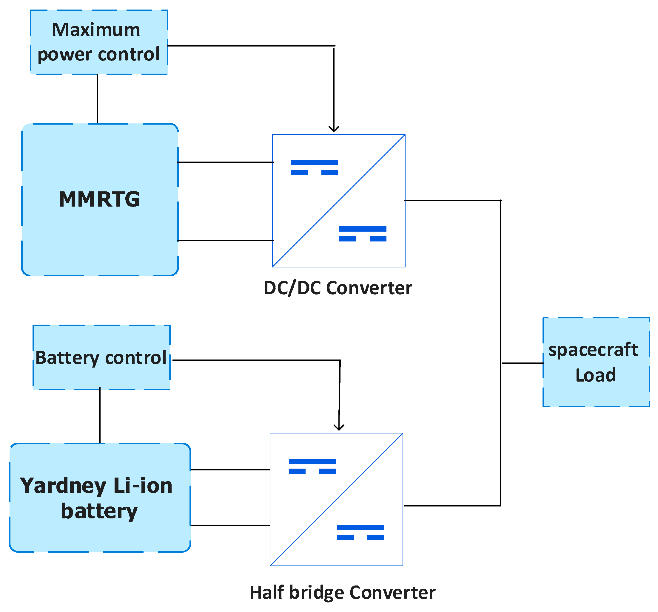
Figure 2.
Li-ion battery discharge behavior.

Figure 3.
(a) Voltage versus Current and (b) Power versus Current of the modeled MMRTG.
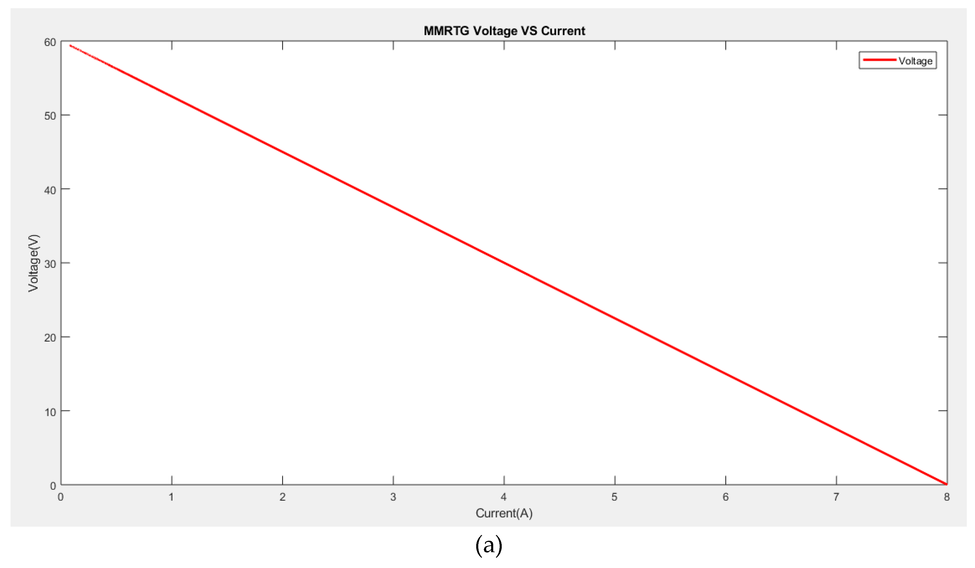
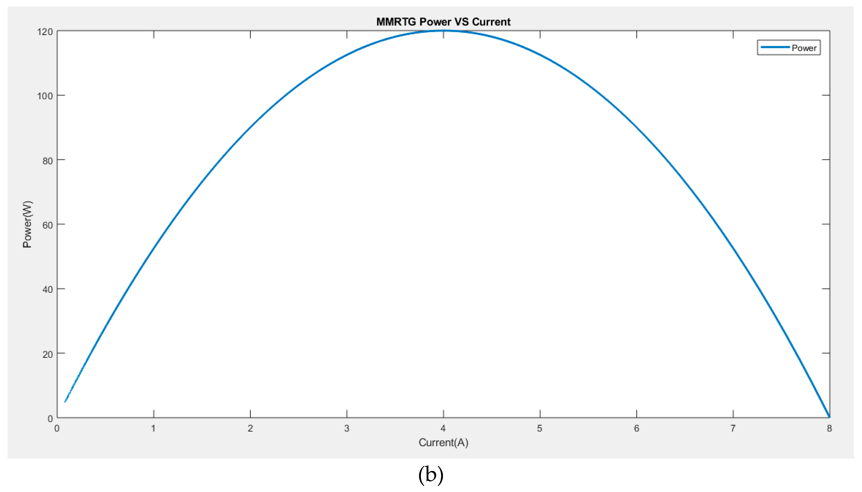
Figure 4.
(a) Output voltage, (b) Load current, and (c) Input and output power of the hybrid battery.
Figure 4.
(a) Output voltage, (b) Load current, and (c) Input and output power of the hybrid battery.
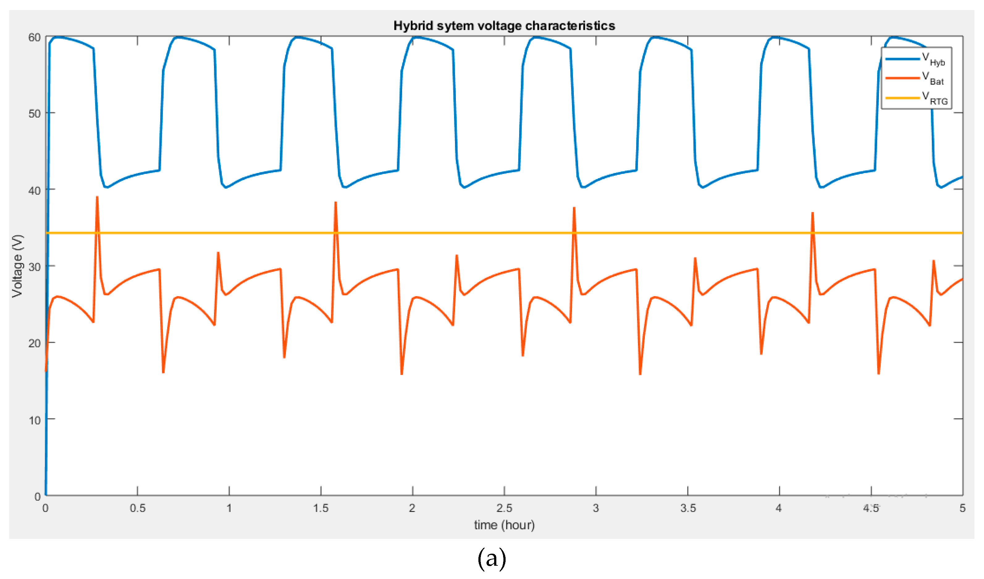
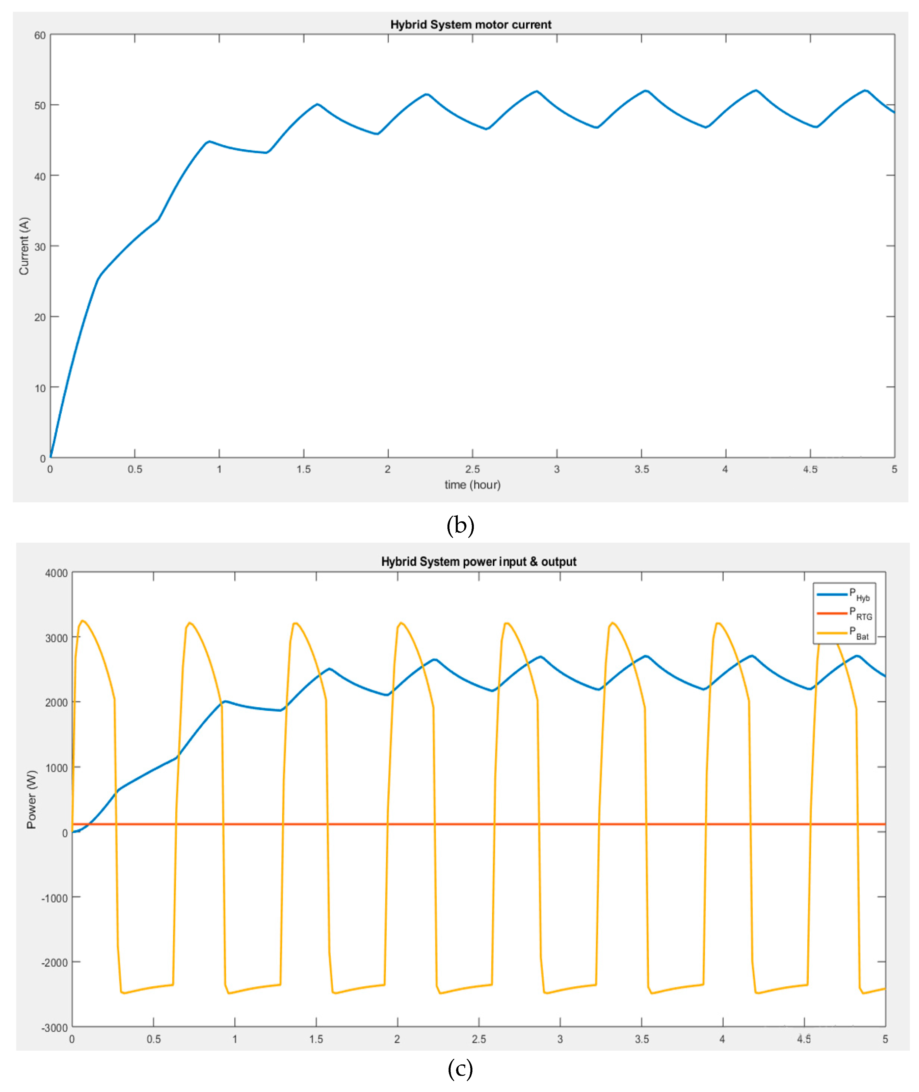
Figure 5.
(a) Output voltage, (b) Load current.
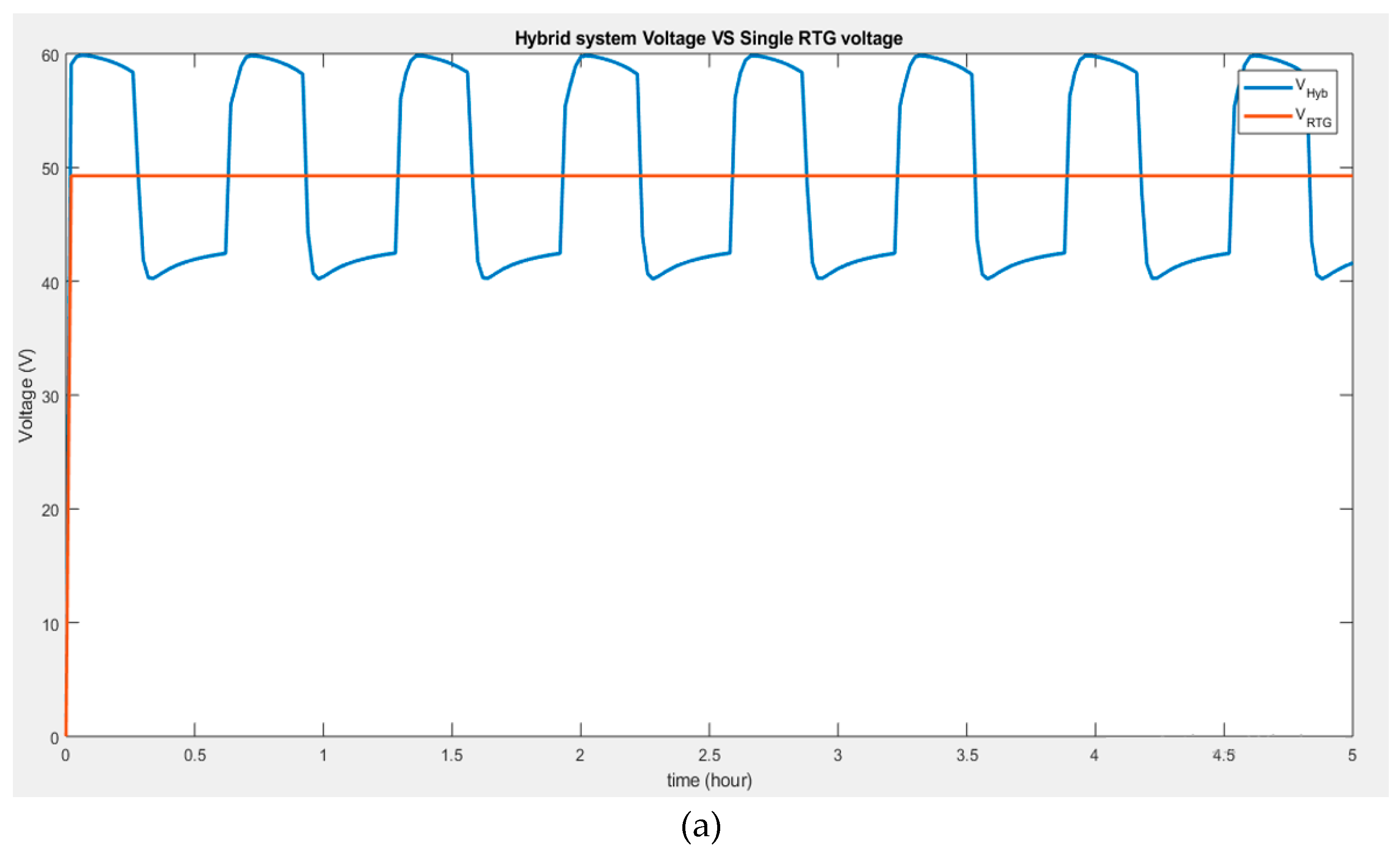
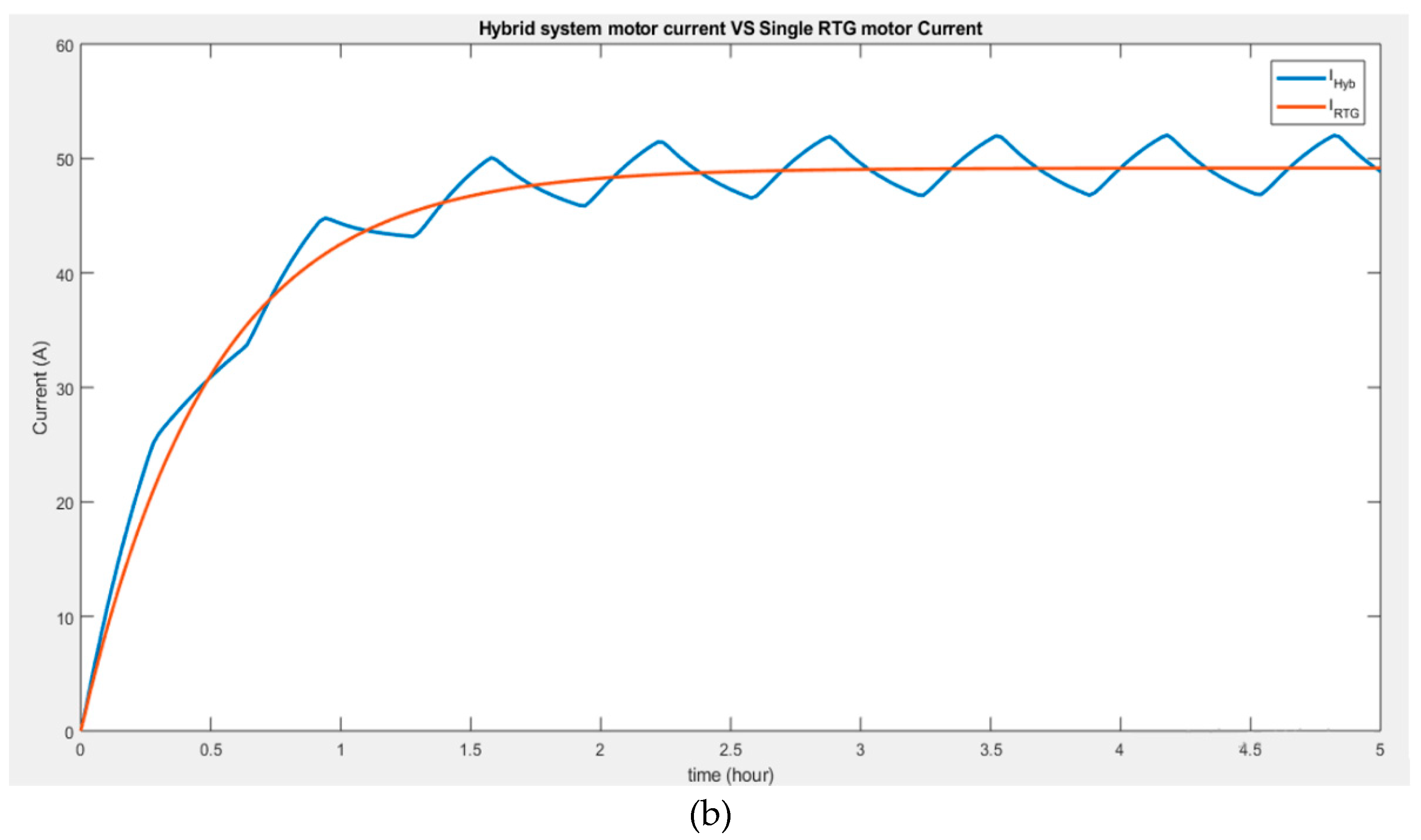
Figure 6.
Performances of hybrid batteries (a) 253oK & 293oK, and (b) at 253oK & 313oK.
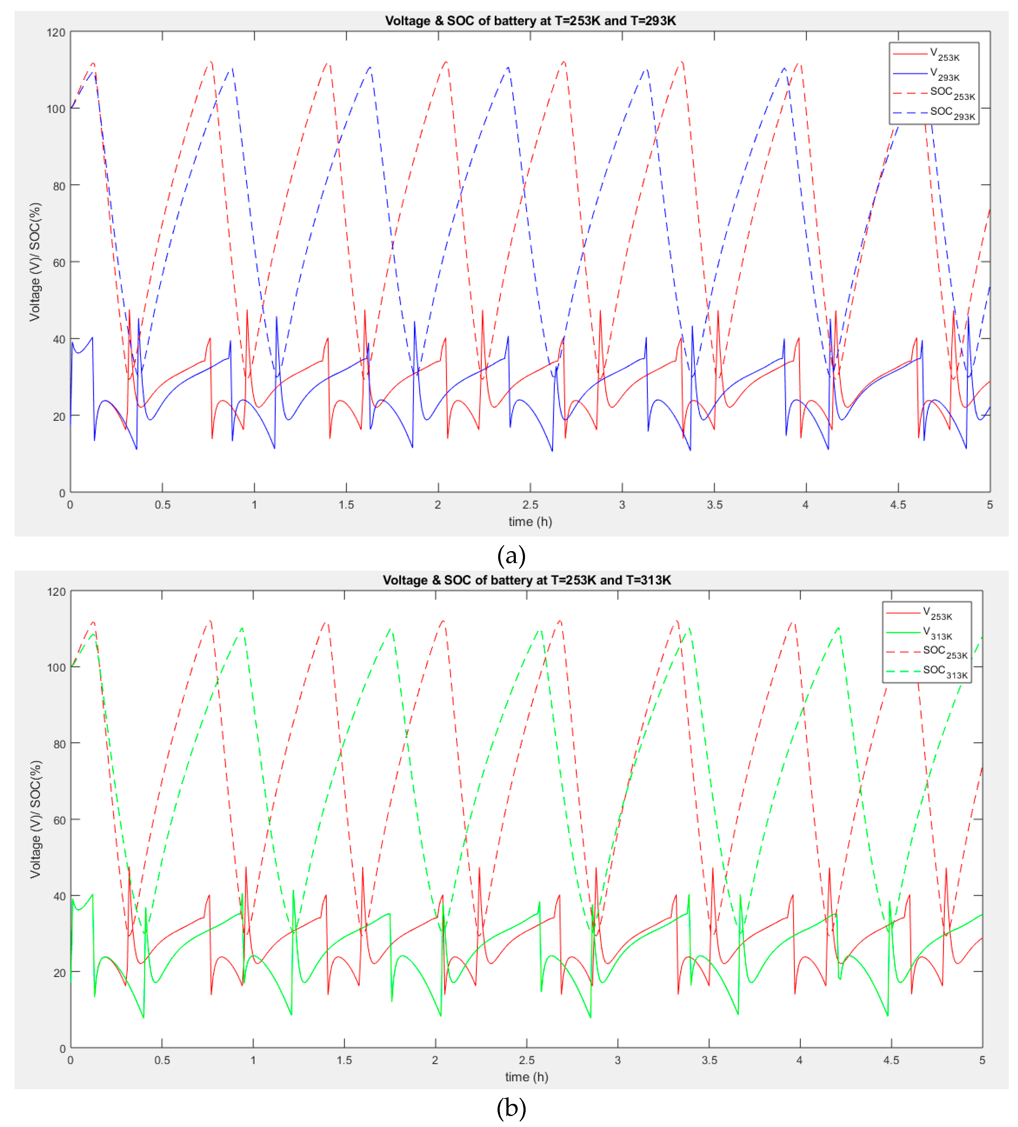

Table 1.
Characteristics of isotope materials used to generate electricity for spacecraft [29].
Table 1.
Characteristics of isotope materials used to generate electricity for spacecraft [29].
| Isotope | Isotope fuel from | Watts cm3 | Half-life | Melting point oC | Weight density g/cm3 | Specific activity W/Kc | Decay particle |
|---|---|---|---|---|---|---|---|
| Po-210 | Metal | 1210 | 138 days | 254 | 9.3 | 31.7 | Alpha |
| Pm-147 | Pm2O3 | 1.5 | 2.6 years | 2300 | 5.55 | 0.37 | Beta |
| Sr-90 | SrO2 | 0.93 | 28 years | 2430 | 2.65 | 6.5 | Beta |
| Pu-238 | PuO2 | 5.0 | 89.6 years | 2250 | 11.46 | 34.5 | Alpha |
| Ce-144 | CeO2 | 13.8 | 285 days | 2680 | 7 | 7.9 | Beta |
Table 1.
Battery characteristics [32].
Table 1.
Battery characteristics [32].
| Specifications | |
|---|---|
| Part Number | LP33450 |
| Nominal Cell Weight | 1.27 kg |
| Voltage Range | 3.0 to 4.1V |
| Nominal Voltage | 3.6V |
| Nominal Capacity | 43Ah at C/5 at 20oC (68oF) |
| Energy Density | 378 Wh/L |
| Specific Energy | 153 Wh/kg |
| Discharge Rates | Max constant current 200A |
| Max pulse current (<1 sec) 400A | |
| Nominal Cell Impedance | 2mΩ at 20oC (68oF) |
| Cycle Life (80% capacity measured at 0.5C discharge current at 20oC (68oF)) | >2000 at 100% DOD |
| Standard Charging Method | Constant current 21.5A (0.5C) to 4.1V |
| Constant voltage 4.1V to 0.86A (C/50) | |
| Operating Temperature | -20 to 60oC (-4 to 140oF) |
| Storage Temperature | -40 to 60oC (-40 to 140oF) |
Table 2.
MMRTG modeling equations and parameter values [39].
Table 2.
MMRTG modeling equations and parameter values [39].
| Design parameters | MMRTG |
| No. of GPHS bricks TE materials No. of couples Design-point QHS TE hot-side temp TE cold-side temp BOL power (WE) Est. EOL (14 years) power BOL system efficiency Specific power (WE kg-1) Containment system Mission usage Addressed program |
8 PbTe(TAGS 85, PbSnTe) 768 1984 WTh @ BOL 525oC 100-200oC ̴120 60 6.0% 2.8 Argon overpressure Multi-mission MSL and Mars 2020 |
| Parameter | Value |
| Efficiency (Thermal to Electrical conversion) Thermal Power Electrical Power Specific power Output voltage Hot-side temperature Cold-side temperature Figure of merit, Z Seebeck coefficient, S Thermal Conductivity, Kth Resistance, R |
6.3 % 2000 W 110 W 2.8 We/Kg 28-32 V dc 525oC (798.15oK) 100-200oC 0.001032 Z-1 0.1818 V/K 4.271 W/K 7.5 Ω |
Table 3.
Motor parameters [40].
Table 3.
Motor parameters [40].
| Description | Value |
| Armature Resistance Ra (Ω) | 1 |
| Armature Inductance La (H) | 0.5 |
| Torque Constant Kt | 0.01 |
| Moment of Inertia J (Kgm2S-2) | 0.01 |
| EMF constant | 0.01 |
| Friction Coefficient B | 0.1 |
Table 4.
Power converters designed parameters.
| Boost converter | |
| Description | Value |
| MMRTE voltage (V) | 34.25 |
| Motor voltage (V) | 60 |
| Switching frequency (kHz) | 25 |
| Voltage ripple | 1% |
| Minimum inductance () | 7 |
| Minimum capacitor (mF) | 1.72 |
| Duty cycle | 43% |
| Half-bridge converter | |
| Battery voltage (V) | 30 |
| Duty cycle | 57% |
| Minimum inductance () | 15 |
| Load capacitor (mF) | 5 |
| Minimum battery capacitor (mF) | 2.3 |
Disclaimer/Publisher’s Note: The statements, opinions and data contained in all publications are solely those of the individual author(s) and contributor(s) and not of MDPI and/or the editor(s). MDPI and/or the editor(s) disclaim responsibility for any injury to people or property resulting from any ideas, methods, instructions or products referred to in the content. |
© 2023 by the authors. Licensee MDPI, Basel, Switzerland. This article is an open access article distributed under the terms and conditions of the Creative Commons Attribution (CC BY) license (http://creativecommons.org/licenses/by/4.0/).
Copyright: This open access article is published under a Creative Commons CC BY 4.0 license, which permit the free download, distribution, and reuse, provided that the author and preprint are cited in any reuse.


