Submitted:
24 April 2023
Posted:
24 April 2023
You are already at the latest version
Abstract
Air conditioners are indispensable necessities in daily life and industrial production. However, the heat generation of their internal core power components can limit their performance release. In this work, we explore the application of thermoelectric coolers (TECs) in the field of power device heat dissipation through finite element simulation. First, we geometrically modeled the structure and typical operating conditions of core power devices in air conditioners. We compared the temperature fields in air cooling and TEC active cooling modes for high power consumption power devices in a 319 K operating environment. The simulation results show that in the single air cooling mode, the maximum temperature of the 173.8 W power device reaches 394.4 K and the average temperature reaches 373.9 K, which exceeds its rated operating temperature of 368.1 K. However, after adding TEC, the maximum temperature of the power device drops to 331.8 K at an operating current of 7.5 A and the average temperature of the device is 326.5 K. It indicates that TEC active cooling has a significant effect on the temperature control of the power device. At the same time, we also studied the effect of TEC working current on the temperature control effect of power devices. For TEC, there is a minimum working current of 5 A; when it is less than 5 A, TEC has no cooling effect; the cooling effect of TEC increases with an increase in working current. When the TEC working current is 10 A, the average temperature of the power device can be reduced to 292.9 K. This study has made a meaningful exploration of the application of TEC in chip temperature control and heat dissipation, providing a new solution for chip thermal management and accurate temperature control.
Keywords:
thermoelectric cooler
; finite element simulation
; power device
; air conditioner
; thermal management
1. Introduction
In modern computer systems, the performance and integration of integrated circuits continue to improve, which is one of the key factors driving the development of computer technology. However, this improvement also brings a serious problem, that is, the thermal management problem of the chip. With the development of Moore's Law, the number of transistors on an integrated circuit increases exponentially, so that the heat generation per unit area also increases exponentially [1,2,3]. When the chip’s operating temperature exceeds the maximum rated temperature, it will cause irreversible damage to its structure [4]. Therefore, when the chip overheats [5], it will reduce its processing frequency through the control circuit to reduce its heat generation and protect itself [6,7]. However, at the same time, the chip’s frequency reduction will also limit its performance release [8,9], and its thermal management problem gradually becomes the bottleneck that limits its performance [10,11,12].
Early on, in order to temperature-control the chip to maximize its performance, it needs to be equipped with huge heat sink fins [13,14,15,16] with cooling fans [17,18,19] to take away the heat of the chip. However, this heat dissipation solution has the disadvantages of large volume and noise. With the development of heat dissipation technology, new solutions have emerged such as water cooling [20] and liquid metal [21,22] and other phase change heat dissipation materials [23,24,25,26]. Through heat pipes that conduct heat from the chip to a thermal medium with high specific heat capacity, phase change process quickly takes away the heat so as to achieve efficient temperature control of the chip [27,28,29,30]. Compared with traditional heat dissipation solutions, this method has the advantages of high efficiency, energy saving and environmental protection. However, introducing fluid media brings new risks to system reliability while volume problems remain unsolved [31]. With increasing integration of electronic products, it is increasingly difficult to meet volume requirements of existing thermal technologies [32,33]. Therefore, there is an urgent need to research and explore a heat dissipation technology that can not only ensure the heat dissipation effect of the chip but also further reduce the volume and weight of electronic products, thereby improving user experience and portability.
Thermoelectric cooling (TEC), is based on the semiconductor’s Peltier effect to achieve direct conversion from electricity to temperature difference [34,35,36,37]. Its principle for refrigeration is shown in Figure 1. Compared with traditional compression refrigeration and phase change absorption refrigeration, semiconductor refrigeration has no transmission parts in its structure, which makes it more reliable and stable with a long life span, maintenance-free and noiseless [30,38,39,40]. In addition, the modularity [41,42], miniaturization [43,44] and efficiency of TEC devices have a good fit with the development of chips, which has a good prospect of application in the field of heat dissipation [45] and temperature control of chips [46]. Moazzez et al used ANSYS CFX software to simulate the air cooling capacity of thermoelectric cooling devices under different conditions to develop the vehicle air conditioning refrigeration system [47]. Chen et al systematically summarized the research progress of the most advanced on-chip thermoelectric cooling devices, and pointed out the development prospects of the design, performance and application of on-chip thermoelectric cooling devices [46]. Saleh used TEC to fabricate a sustainable self-cooling frame for cooling chip hot spots, which successfully cooled the hot spots at an acceptable temperature and reduced the unevenness of chip temperature distribution [48]. Li et al proposed a chip-on-TEC for active thermal management of high-power light-emitting diodes (LED), and the study showed that at an operating current of 1.0 A, it not only reduced the chip temperature by 51% but also increased light output power of the LED [49].
In this work, we selected a typical working condition of several core power devices in an air conditioner [50,51] and established a multi-physics field model with the help of COMSOL finite element analysis software [52,53,54,55]. Then, we compared the temperature field under conventional air cooling with that after adding a TEC device, and analyzed the effect of TEC operating current on the chip temperature. It provides a new solution for the cooling of core components in air conditioners.
2. Experimental
Geometric modeling: The heat dissipation structure of the power device after adding TEC is shown in Figure 2. To ensure the reliability of the power device in application, it is usually packaged, and the upper part is connected to the protective case through thermal interface material, and the lower part is connected to the PCB board through welding. TEC is set at the lower end of the PCB to directly cool the chip, and the heat is taken away through the air duct through the cooling fins under the TEC. In order to study the effect of TEC on the temperature control of the chip in this structure, this paper establishes geometric models for the two heat dissipation models of the chip cooling through the cooling fins and TEC combined with air cooling.
The TEC simulation model is shown in Figure 3, with a sandwich structure consisting of an upper ceramic substrate, upper electrodes, thermoelectric units, lower electrodes, and a lower ceramic substrate from top to bottom. The TEC planar size is 35 × 57 mm2, and the total thickness in the vertical direction is 3.8 mm, and the size and amount of the thermoelectric leg are 1.4 × 1.4 × 1.6 mm³ and 416 respectively. The thickness of the ceramic substrate and electrode are 0.8 mm and 0.3 mm respectively. The geometric model of TEC forced cooling combined with fin air cooling is shown in Figure 4, and the model consists of power devices, TECs, heat sink fins and air ducts. The dimensions of the three core power devices are 35 × 57 × 3 mm³, 20 × 30 × 3 mm³, and 20 × 30 × 3 mm³, corresponding to a power consumption of 173.81 W, 27.5 W, and 27.5 W, respectively, and an effective heat dissipation area of 1995 mm², 587 mm², and 587 mm², respectively. The dimensions of the TEC are as described above with a flat fin size of 196 × 210 mm², including 30 fins and a center fin size of 52 × 210 × 1.5 mm³. The air duct size is 430 × 230 × 86 mm³. The contact interface between the TEC, power device and fin are connected by a thermally conductive silicone grease with a thickness of 0.15 mm to ensure good contact heat conduction.
Material property parameter setting: “FR4” from the material library of COMSOL Multiphysics 5.6 is used as the material of the circuit board, “6063 [solid]” alloy is used as the material of the heat sink fin, “Air” is used as the material of the fluid heat transfer medium. The rest materials in the model are custom materials and the specific material properties [56] are shown in Table 1.
Multi-physical field setting: We invoke four physical field modules in COMSOL Multiphysics 5.6 for coupling solid and fluid heat transfer, laminar flow, current and thermoelectric effects. Then we need to define the initial conditions and boundary conditions to determine the heat generation and heat transfer of the simulation models.
Initial conditions: the initial test temperature of all components in the model is 298.15 K (25 °C), the ambient temperature is 319.15 K (46 °C), and the wind speed at the inlet of the duct is 1.5 m s-1.
Boundary conditions: The heat source of the power device is set by the domain heat source model in COMSOL, and the generalized source heat densities are 29040935.672, 15393226.98, and 15393226.98 W m-3. The heat transfer coefficients of the contact surfaces between the heat sink fins and the air medium in the air duct in the air-cooled region are calculated by the laminar flow model.
Natural convection heat dissipation between air and power device and TEC can be described by Fourier’s law convective heat transfer process using this equation:
Where h is the convective heat transfer coefficient and Tambient is the ambient temperature.
Referring to the convective heat transfer coefficient calculation model provided in COMSOL, the convective heat transfer coefficients at different locations for different materials in the TEC structure can be divided into three categories: top surface, bottom surface and side surface , which we will discuss separately below.
The convective heat transfer coefficient (htop) between the TEC substrate and the electrode top surface can be calculated according to the following equation:
In the above equation, κ is the thermal conductivity of the heat transfer medium (air), L is the characteristic length (defined as the area/perimeter of the contact surface), and RaL is the Rayleigh number.
The heat transfer coefficient (hbot) of the TEC bottom surface can be calculated as:
The heat transfer coefficient (hside) of the side of the TEC can be calculated according to the following equation:
Where μ and Cp are the dynamic viscosity and heat capacity of air at qualitative temperature Tq, respectively. Tq is defined as (Tside + Tambient)/2.
The above three sets of equations allow us to accurately describe the convective heat transfer coefficients at different locations of the TEC in the simulation model, making the simulation results closer to the actual situation.
To simplify the model and reduce the amount of calculation, the following reasonable assumptions are proposed:
(1) Only heat convection and heat exchange are considered, and the influence of heat radiation is not considered;
(2) The surface of cooling fin is regarded as an ideal plane, regardless of the influence of surface roughness on air viscous heat transfer coefficient;
(3) Simplify the contact interface between the cooling fin and the TEC, replace it with a thermally conductive silicone grease layer.
Finite element network division: The division technique of finite element network is to divide each domain into smaller-sized subdomains of various shapes, and these subdomains are called finite elements. The more nodes of the primitive, the smaller the calculation error, and the tiny parts can also be reflected, and the longer the calculation time is also. Reasonable grid division can obtain more accurate calculation results, in this paper, triangles are used to divide the mesh unit,the division results are shown in Figure 5 and Figure 6. In this model, 196169 fixed points were selected and there were 821207 cells with an average cell mass of 0.65.
3. Results and Discussion
Firstly, we simulated the temperature distribution of the system when the three power devices were operated with 173.8 W, 27.5 W and 27.5 W heat generation at 46°C, respectively, only through air cooling with the heat sink fins and air duct. When the air inlet speed at the duct inlet is 1.5 ms-1, the air flow velocity distribution in the duct is shown in Figure 7. The air flow velocity at the fin surface is close to the air velocity at the inlet and the streamlined fin configuration effectively reduces the effect of air sticking resistance on the heat transfer coefficient at the fin surface.
Figure 8 shows the temperature distribution of different components in the system under convectional air cooling. As can be seen from Figure 8a, the temperature distribution of each component in the system from high to low is power device, heat sink fin, and air duct. Obviously, the heat is mainly concentrated on the power devices. The surface temperature of the power devices is proportional to their heat generation, and the heat sink fins do not have a significant effect on the cooling of the power devices. From Figure 8b,c, we can see that the maximum temperature of the high heat generating power device is 394.4 K, and the average temperature is 373.9 K, which exceeds its rated operating temperature of 368.1 K, while the maximum temperature of the low power device is 371.6 K, and the average temperature is 358.2 K. Figure 8d shows the surface temperature distribution of the heat sink fins. The temperature difference between the contact position of the power device and the heat sink fins is not significant, which indicates that the uniform temperature performance of the heat sink fins can meet the heat generation of the power device, so that most of the heat is transferred to the air through the heat sink fins. The maximum surface temperature of the heat sink fin is 363.8 K and the average temperature is 348.5 K.
Then we added a TEC under the power device with high heat generation. The heat generated by the power device is actively carried to the heat sink fins through the heat pump effect of TEC. The power device is temperature-controlled by active TEC cooling combined with passive heat dissipation of the heat sink fins. When the TEC operating current is 7.5A, the temperature distribution of each component of the system is shown in Figure 9.
As can be seen from Figure 9a, in the mode combining TEC active cooling with passive fin cooling, the temperature distribution of each component in the system from high to low is the power device without TEC, heat sink fin, air duct and the high power device with TEC. The temperature distribution of the parts without TEC is basically the same as that under single air cooling, but the temperature of the high power consumption power device with TEC is significantly lower. The air temperature in the air duct is also different from that in the air-cooled heat sink. Because more heat is transferred to the air through convection heat transfer, the air temperature is higher.
The maximum temperature of the high power consumption power device is 331.8 K (Figure 9b), and the average temperature of the power device is 326.5 K. Compared with the single air cooling, the maximum temperature of the power device after adding TEC drops 62.6 K, and the average temperature drops 47.4 K, which shows that TEC active cooling has a significant effect on the temperature field of the power device. The maximum temperature of the low power consumption power device is 369.1 K and the average temperature is 358.8 K (Figure 9c). Compared with that in the air cooling mode, the maximum temperature of the device is lower, while the average temperature is higher. It indicates that the TEC actively transports the heat from the high power consumption power device to the heat sink fins, and then the heat is transferred to the lower power consumption power device through the heat sink fins.
The temperature distribution on the heat sink fins is basically the same as that under single air cooling, with the maximum temperature of the heat sink fins dropping from 363.8 K to 363.3 K and the average temperature rising from 348.5 K to 348.6 K (Figure 9d). The above simulation results show that the temperature of the power device is well controlled after the addition of TEC. This is of great significance for the performance release and service life of the power device.
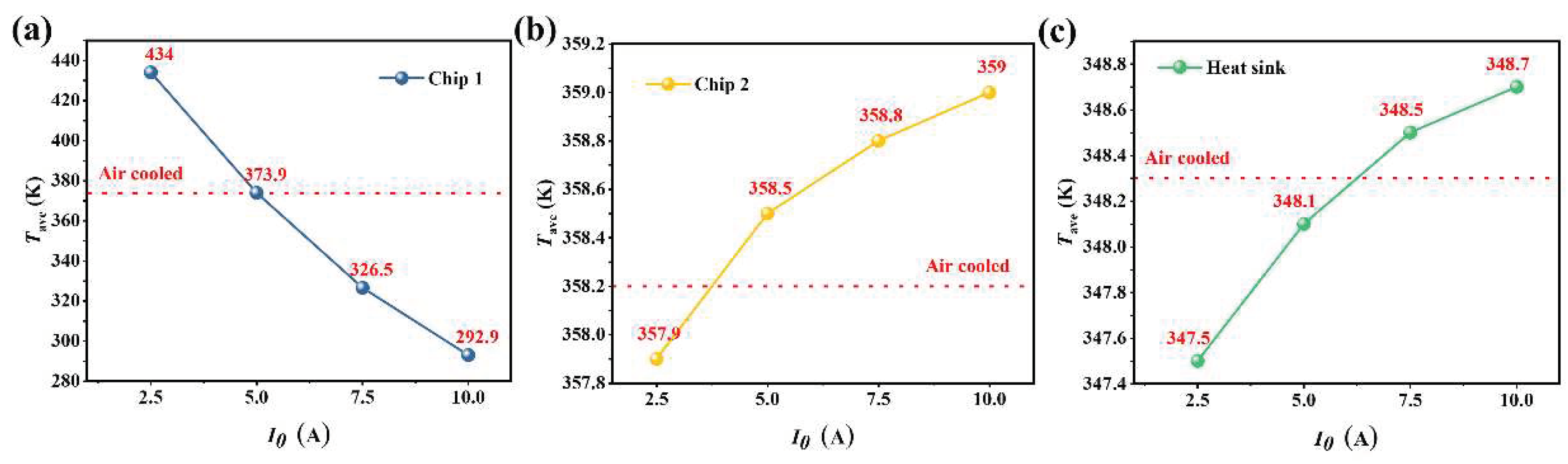
The previous research proved that the addition of TEC under constant operating current can effectively control the temperature of power devices. Therefore, in order to further explore the reliability of TEC temperature control, the effect of TEC on the operating temperature of power devices under different operating currents was experimentally studied, we simulated the temperature field of the system under different TEC working currents systematically. The average temperature of high power consumption power device, low power consumption power devices and heat sink fins in the system varies with the working current of TEC, as shown in Figure 10. It can be seen that when the working current of TEC is less than 5A, TEC has no active cooling effect on power devices even the temperature is higher than that under air cooling. This is because the cooling capacity of TEC is related to the working current, and TEC itself can also be regarded as a thermal resistance, of which the resistance varies with the working current in the heat transfer path. When the active cooling capacity minus the Joule heat is less than the original thermal conductivity, the thermal resistance effect will be realized. From the simulation results, the minimum working current of TEC to achieve cooling effect should reach 5 A under this working condition. When the working current of TEC is further increased to 7.5 A and 10 A, the temperature of the cooled high power consumption power device can be further reduced to 326.5 K and 292.9 K, and the temperature control effect is very significant. At the same time, the nearby low power consumption power devices and heat sink fins will heat up because of the heat pump effect of TEC, and the increase of the temperature of the heat sink fins will also help to improve the air-cooled heat transfer.
4. Conclusions
This work explores the active heat dissipation of thermoelectric cooling (TEC) for power devices in air conditioners through COMSOL finite element simulations. The simulation results show that in the single-air cooling mode, the maximum temperature of the power device with 173.8 W power consumption reaches 394.4 K and the average temperature reaches 373.9 K, which exceeds its rated operating temperature of 368.1 K; however, after adding TEC, the maximum temperature of the power device drops to 331.8 K at an operating current of 7.5 A and the average temperature of the device is 326.5 K. Obviously, compared to single air-cooling, the maximum temperature of the power device drops 62.6 K and the average temperature drops 47.4 K after adding TEC, indicating that TEC active cooling has a significant effect on the temperature control of the power device. At the same time, we studies the effect of TEC operating current on the temperature control effect of the power device, and there is a minimum TEC operating current of 5 A.
Author Contributions
J.W. and K.H. contributed equally to this work. D.W.Y. and Y.G.Y. conceived the project; J.W., K.C.T. and Y.B.X. carried out the finite element simulation; D.W.Y., J.W., K.H., Y.N.X., Y.T.L. and Y.G.Y. analyzed the data; J.W., K.H. and D.W.Y. co-wrote the manuscript. All authors have read and agreed to the published version of the manuscript.
Funding
The authors declare no competing financial interest.
Acknowledgements
This work was financially supported by the National Natural Science Foundation of China (52202289), the International Postdoctoral Exchange Fellowship Program (PC2022044), and the National Key Research and Development Program of China (2019YFA0704900).
References
- Puttaswamy, K.; Loh, G.H. Thermal Analysis of a 3D Die-Stacked High-Performance Microprocessor. In Proceedings of the Proceedings of the 16th ACM Great Lakes symposium on VLSI; 2006; pp. 19–24.
- Nada, S.; Alshaer, W. Comprehensive Parametric Study of Using Carbon Foam Structures Saturated with PCMs in Thermal Management of Electronic Systems. Energy Convers. Manag. 2015, 105, 93–102. [CrossRef]
- Mathew, J.; Krishnan, S. A Review on Transient Thermal Management of Electronic Devices. J. Electron. Packag. 2022, 144. [CrossRef]
- Brooks, D.; Martonosi, M. Dynamic Thermal Management for High-Performance Microprocessors. In Proceedings of the Proceedings HPCA Seventh International Symposium on High-Performance Computer Architecture; IEEE, 2001; pp. 171–182.
- Haywood, A.M.; Sherbeck, J.; Phelan, P.; Varsamopoulos, G.; Gupta, S.K. The Relationship among CPU Utilization, Temperature, and Thermal Power for Waste Heat Utilization. Energy Convers. Manag. 2015, 95, 297–303. [CrossRef]
- Su, Y.; Zhang, M.; Chitrakar, B.; Zhang, W. Effects of Low-Frequency Ultrasonic Pre-Treatment in Water/Oil Medium Simulated System on the Improved Processing Efficiency and Quality of Microwave-Assisted Vacuum Fried Potato Chips. Ultrason. Sonochem. 2020, 63, 104958. [CrossRef]
- Moscoso, W.; Olgun, E.; Compton, W.D.; Chandrasekar, S. Effect of Low-Frequency Modulation on Lubrication of Chip-Tool Interface in Machining. J Trib 2005, 127, 238–244. [CrossRef]
- Cebrián, J.M.; Natvig, L.; Meyer, J.C. Performance and Energy Impact of Parallelization and Vectorization Techniques in Modern Microprocessors. Computing 2014, 96, 1179–1193. [CrossRef]
- Bowman, K.A.; Alameldeen, A.R.; Srinivasan, S.T.; Wilkerson, C.B. Impact of Die-to-Die and within-Die Parameter Variations on the Clock Frequency and Throughput of Multi-Core Processors. IEEE Trans. Very Large Scale Integr. VLSI Syst. 2009, 17, 1679–1690. [CrossRef]
- Le Sueur, E.; Heiser, G. Dynamic Voltage and Frequency Scaling: The Laws of Diminishing Returns. In Proceedings of the Proceedings of the 2010 international conference on Power aware computing and systems; 2010; pp. 1–8.
- Suszko, A.; El-Genk, M.S. Thermally Anisotropic Composite Heat Spreaders for Enhanced Thermal Management of High-Performance Microprocessors. Int. J. Therm. Sci. 2016, 100, 213–228. [CrossRef]
- Kong, J.; Chung, S.W.; Skadron, K. Recent Thermal Management Techniques for Microprocessors. ACM Comput. Surv. CSUR 2012, 44, 1–42. [CrossRef]
- Li, Y.; Gong, L.; Ding, B.; Xu, M.; Joshi, Y. Thermal Management of Power Electronics with Liquid Cooled Metal Foam Heat Sink. Int. J. Therm. Sci. 2021, 163, 106796. [CrossRef]
- Laloya, E.; Lucia, O.; Sarnago, H.; Burdio, J.M. Heat Management in Power Converters: From State of the Art to Future Ultrahigh Efficiency Systems. IEEE Trans. Power Electron. 2015, 31, 7896–7908. [CrossRef]
- Shatikian, V.; Ziskind, G.; Letan, R. Numerical Investigation of a PCM-Based Heat Sink with Internal Fins. Int. J. Heat Mass Transf. 2005, 48, 3689–3706. [CrossRef]
- Lee, Y.J.; Singh, P.K.; Lee, P.S. Fluid Flow and Heat Transfer Investigations on Enhanced Microchannel Heat Sink Using Oblique Fins with Parametric Study. Int. J. Heat Mass Transf. 2015, 81, 325–336. [CrossRef]
- Qi, Z. Advances on Air Conditioning and Heat Pump System in Electric Vehicles–A Review. Renew. Sustain. Energy Rev. 2014, 38, 754–764. [CrossRef]
- Jin, X.; Ma, E.W.; Cheng, L.L.; Pecht, M. Health Monitoring of Cooling Fans Based on Mahalanobis Distance with MRMR Feature Selection. IEEE Trans. Instrum. Meas. 2012, 61, 2222–2229. [CrossRef]
- Leroy, A.; Bhatia, B.; Kelsall, C.C.; Castillejo-Cuberos, A.; Di Capua H, M.; Zhao, L.; Zhang, L.; Guzman, A.; Wang, E. High-Performance Subambient Radiative Cooling Enabled by Optically Selective and Thermally Insulating Polyethylene Aerogel. Sci. Adv. 2019, 5, eaat9480. [CrossRef]
- Xiang, X.; Yang, J.; Fan, A.; Liu, W. A Comparison between Cooling Performances of Water-Based and Gallium-Based Micro-Channel Heat Sinks with the Same Dimensions. Appl. Therm. Eng. 2018, 137, 1–10. [CrossRef]
- Khan, Y.; Sarowar, M.T.; Mobarrat, M.; Rahman, M.H. Performance Comparison of a Microchannel Heat Sink Using Different Nano-Liquid Metal Fluid Coolant: A Numerical Study. J. Therm. Sci. Eng. Appl. 2022, 14, 091014. [CrossRef]
- Muhammad, A.; Selvakumar, D.; Iranzo, A.; Sultan, Q.; Wu, J. Comparison of Pressure Drop and Heat Transfer Performance for Liquid Metal Cooled Mini-Channel with Different Coolants and Heat Sink Materials. J. Therm. Anal. Calorim. 2020, 141, 289–300. [CrossRef]
- Li, M.; Wei, J.; Tao, W. Numerical Simulation of Dropwise Condensation on Rough Structures in the Presence of Non-Condensable Gas Using LBM. Numer. Heat Transf. Part Appl. 2021, 79, 450–462. [CrossRef]
- Sivasamy, P.; Devaraju, A.; Harikrishnan, S. Review on Heat Transfer Enhancement of Phase Change Materials (PCMs). Mater. Today Proc. 2018, 5, 14423–14431. [CrossRef]
- Yang, L.; Jin, X.; Zhang, Y.; Du, K. Recent Development on Heat Transfer and Various Applications of Phase-Change Materials. J. Clean. Prod. 2021, 287, 124432. [CrossRef]
- Wu, Y.; Zhang, X.; Xu, X.; Lin, X.; Liu, L. A Review on the Effect of External Fields on Solidification, Melting and Heat Transfer Enhancement of Phase Change Materials. J. Energy Storage 2020, 31, 101567. [CrossRef]
- Wang, X.; Luo, L.; Xiang, J.; Zheng, S.; Shittu, S.; Wang, Z.; Zhao, X. A Comprehensive Review on the Application of Nanofluid in Heat Pipe Based on the Machine Learning: Theory, Application and Prediction. Renew. Sustain. Energy Rev. 2021, 150, 111434. [CrossRef]
- Tang, H.; Tang, Y.; Wan, Z.; Li, J.; Yuan, W.; Lu, L.; Li, Y.; Tang, K. Review of Applications and Developments of Ultra-Thin Micro Heat Pipes for Electronic Cooling. Appl. Energy 2018, 223, 383–400. [CrossRef]
- Zhu, L.; Tan, H.; Yu, J. Analysis on Optimal Heat Exchanger Size of Thermoelectric Cooler for Electronic Cooling Applications. Energy Convers. Manag. 2013, 76, 685–690. [CrossRef]
- Byon, C. Heat Pipe and Phase Change Heat Transfer Technologies for Electronics Cooling. Electron. Cool. 2016. [CrossRef]
- Abdelkareem, M.A.; Maghrabie, H.M.; Sayed, E.T.; Kais, E.-C.A.; Abo-Khalil, A.G.; Al Radi, M.; Baroutaji, A.; Olabi, A. Heat Pipe-Based Waste Heat Recovery Systems: Background and Applications. Therm. Sci. Eng. Prog. 2022, 101221. [CrossRef]
- Baby, R.; Balaji, C. Thermal Management of Electronics Using Phase Change Material Based Pin Fin Heat Sinks. In Proceedings of the Journal of Physics: Conference Series; IOP Publishing, 2012; Vol. 395, p. 012134. [CrossRef]
- Goharshadi, E.; Ahmadzadeh, H.; Samiee, S.; Hadadian, M. Nanofluids for Heat Transfer Enhancement-a Review. 2013. [CrossRef]
- Zhao, D.; Tan, G. A Review of Thermoelectric Cooling: Materials, Modeling and Applications. Appl. Therm. Eng. 2014, 66, 15–24. [CrossRef]
- Enescu, D.; Virjoghe, E.O. A Review on Thermoelectric Cooling Parameters and Performance. Renew. Sustain. Energy Rev. 2014, 38, 903–916. [CrossRef]
- Chen, W.; Shi, X.; Zou, J.; Chen, Z. Thermoelectric Coolers: Progress, Challenges, and Opportunities. Small Methods 2022, 6, 2101235. [CrossRef]
- Pourkiaei, S.M.; Ahmadi, M.H.; Sadeghzadeh, M.; Moosavi, S.; Pourfayaz, F.; Chen, L.; Yazdi, M.A.P.; Kumar, R. Thermoelectric Cooler and Thermoelectric Generator Devices: A Review of Present and Potential Applications, Modeling and Materials. Energy 2019, 186, 115849. [CrossRef]
- Bansal, P.; Martin, A. Comparative Study of Vapour Compression, Thermoelectric and Absorption Refrigerators. Int. J. Energy Res. 2000, 24, 93–107. [CrossRef]
- Liang, K.; Li, Z.; Chen, M.; Jiang, H. Comparisons between Heat Pipe, Thermoelectric System, and Vapour Compression Refrigeration System for Electronics Cooling. Appl. Therm. Eng. 2019, 146, 260–267. [CrossRef]
- Chougule, S.S.; Sahu, S. Thermal Performance of Nanofluid Charged Heat Pipe with Phase Change Material for Electronics Cooling. J. Electron. Packag. 2015, 137, 021004. [CrossRef]
- Zhang, W.; Shen, L.; Yang, Y.; Chen, H. Thermal Management for a Micro Semiconductor Laser Based on Thermoelectric Cooling. Appl. Therm. Eng. 2015, 90, 664–673. [CrossRef]
- Shen, L.; Chen, H.; Xiao, F.; Yang, Y.; Wang, S. The Step-Change Cooling Performance of Miniature Thermoelectric Module for Pulse Laser. Energy Convers. Manag. 2014, 80, 39–45. [CrossRef]
- Singh, V.; Sisodia, S.; Patel, A.; Shah, T.; Das, P.; Patel, R.; Bhavsar, R. Thermoelectric Cooler (TEC) Based Thermal Control System for Space Applications: Numerical Study. Appl. Therm. Eng. 2023, 224, 120101. [CrossRef]
- Gillott, M.; Jiang, L.; Riffat, S. An Investigation of Thermoelectric Cooling Devices for Small-Scale Space Conditioning Applications in Buildings. Int. J. Energy Res. 2010, 34, 776–786. [CrossRef]
- Cai, Y.; Wang, Y.; Liu, D.; Zhao, F.-Y. Thermoelectric Cooling Technology Applied in the Field of Electronic Devices: Updated Review on the Parametric Investigations and Model Developments. Appl. Therm. Eng. 2019, 148, 238–255. [CrossRef]
- Chen, W.-Y.; Shi, X.-L.; Zou, J.; Chen, Z.-G. Thermoelectric Coolers for On-Chip Thermal Management: Materials, Design, and Optimization. Mater. Sci. Eng. R Rep. 2022, 151, 100700. [CrossRef]
- Moazzez, A.F.; Najafi, G.; Ghobadian, B.; Hoseini, S.S. Numerical Simulation and Experimental Investigation of Air Cooling System Using Thermoelectric Cooling System. J. Therm. Anal. Calorim. 2020, 139, 2553–2563. [CrossRef]
- Al-Shehri, S.A. Cooling Computer Chips with Cascaded and Non-Cascaded Thermoelectric Devices. Arab. J. Sci. Eng. 2019, 44, 9105–9126. [CrossRef]
- Li, S.; Liu, J.; Ding, L.; Liu, J.; Xu, J.; Peng, Y.; Chen, M. Active Thermal Management of High-Power LED Through Chip on Thermoelectric Cooler. IEEE Trans. Electron Devices 2021, 68, 1753–1756. [CrossRef]
- Teng, T.-P.; Mo, H.-E.; Lin, H.; Tseng, Y.-H.; Liu, R.-H.; Long, Y.-F. Retrofit Assessment of Window Air Conditioner. Appl. Therm. Eng. 2012, 32, 100–107. [CrossRef]
- Said, M.; Hassan, H. Impact of Energy Storage of New Hybrid System of Phase Change Materials Combined with Air-Conditioner on Its Heating and Cooling Performance. J. Energy Storage 2021, 36, 102400. [CrossRef]
- Ma, K.; Zuo, Z.; Wang, W. Design and Experimental Study of an Outdoor Portable Thermoelectric Air-Conditioning System. Appl. Therm. Eng. 2023, 219, 119471. [CrossRef]
- Seyednezhad, M.; Najafi, H. Numerical Analysis and Parametric Study of a Thermoelectric-Based Radiant Ceiling Panel for Building Cooling Applications. In Proceedings of the ASME International Mechanical Engineering Congress and Exposition; American Society of Mechanical Engineers, 2020; Vol. 84560, p. V008T08A030.
- Manikandan, S.; Selvam, C.; Pavan Sai Praful, P.; Lamba, R.; Kaushik, S.; Zhao, D.; Yang, R. A Novel Technique to Enhance Thermal Performance of a Thermoelectric Cooler Using Phase-Change Materials. J. Therm. Anal. Calorim. 2020, 140, 1003–1014. [CrossRef]
- Venkatesan, K.; Venkataramanan, M. Experimental and Simulation Studies on Thermoelectric Cooler: A Performance Study Approach. Int. J. Thermophys. 2020, 41, 1–23. [CrossRef]
- Hu, K.; Yang, D.; Hui, Y.; Zhang, H.; Song, R.; Liu, Y.; Wang, J.; Wen, P.; He, D.; Liu, X.; et al. Optimized Thermal Design for Excellent Wearable Thermoelectric Generator. J. Mater. Chem. A 2022, 10, 24985–24994. [CrossRef]
Figure 1.
Principle of TEC.
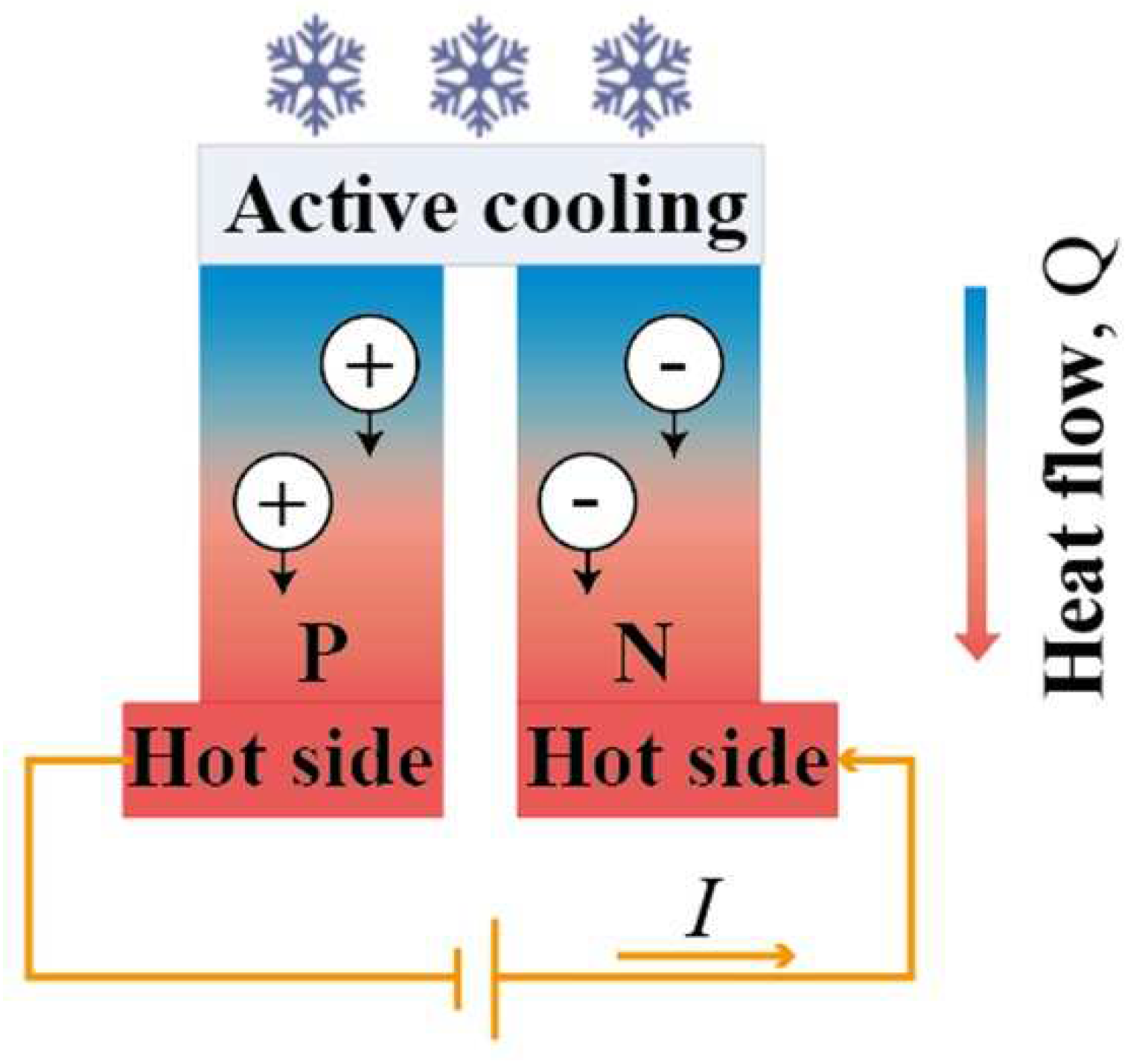
Figure 2.
Heat dissipation structure for temperature control of power devices.
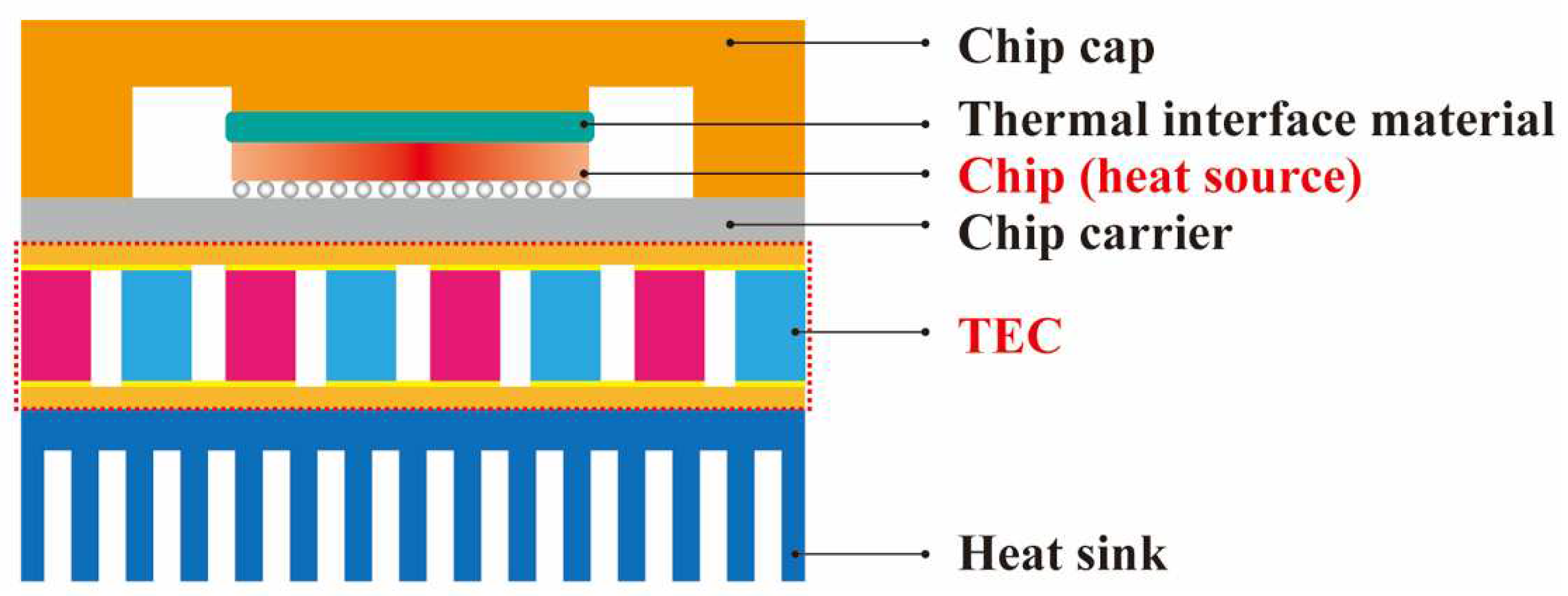
Figure 3.
Simulation model of TEC.
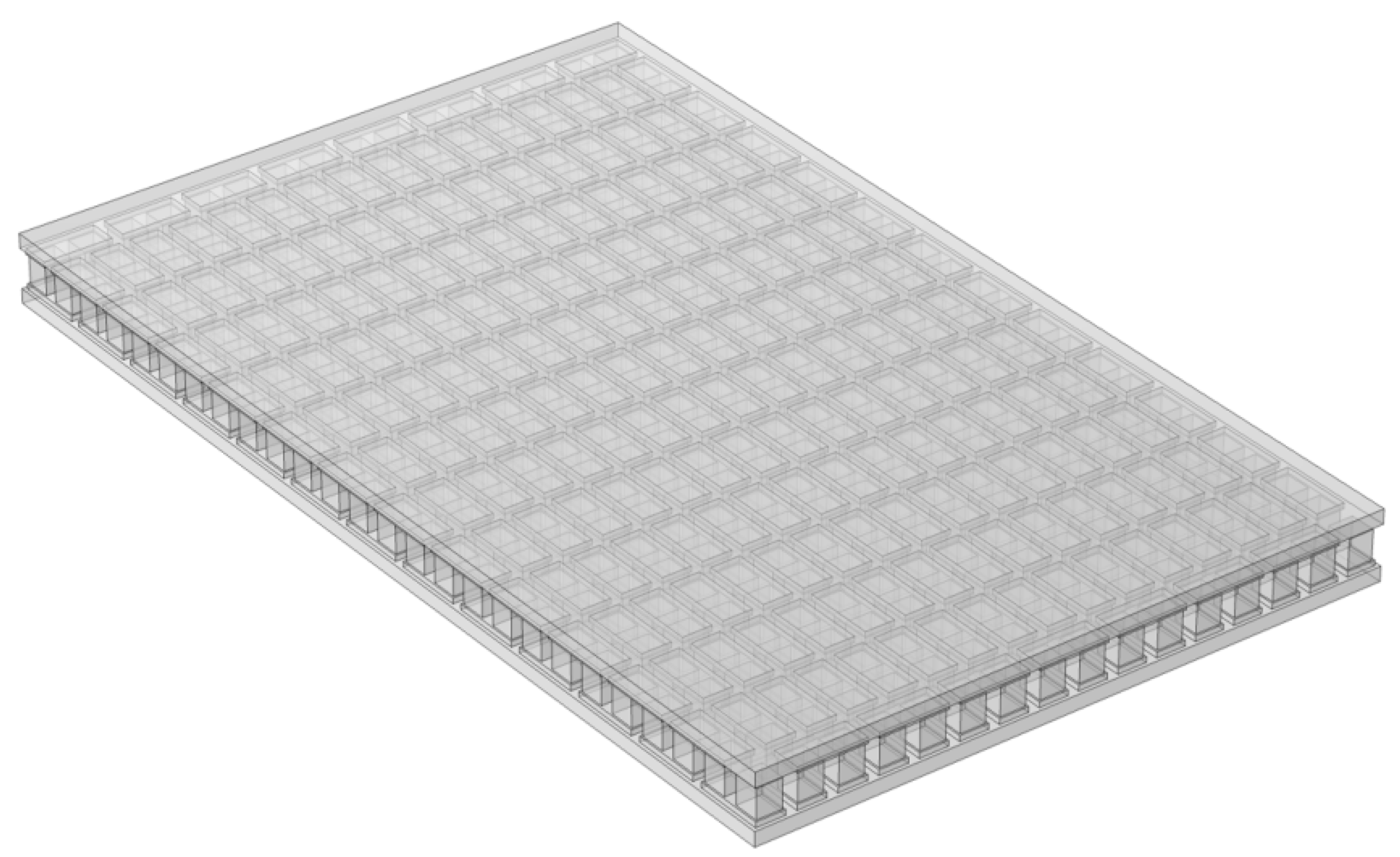
Figure 4.
Fluid heat transfer simulation model of TEC forced cooling combined with finned air cooling.
Figure 4.
Fluid heat transfer simulation model of TEC forced cooling combined with finned air cooling.
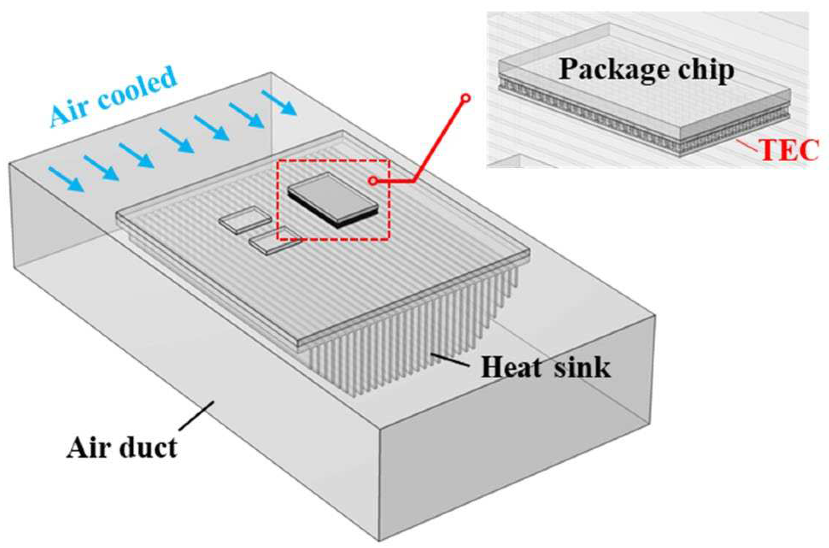
Figure 5.
Finite element network devision of TEC.
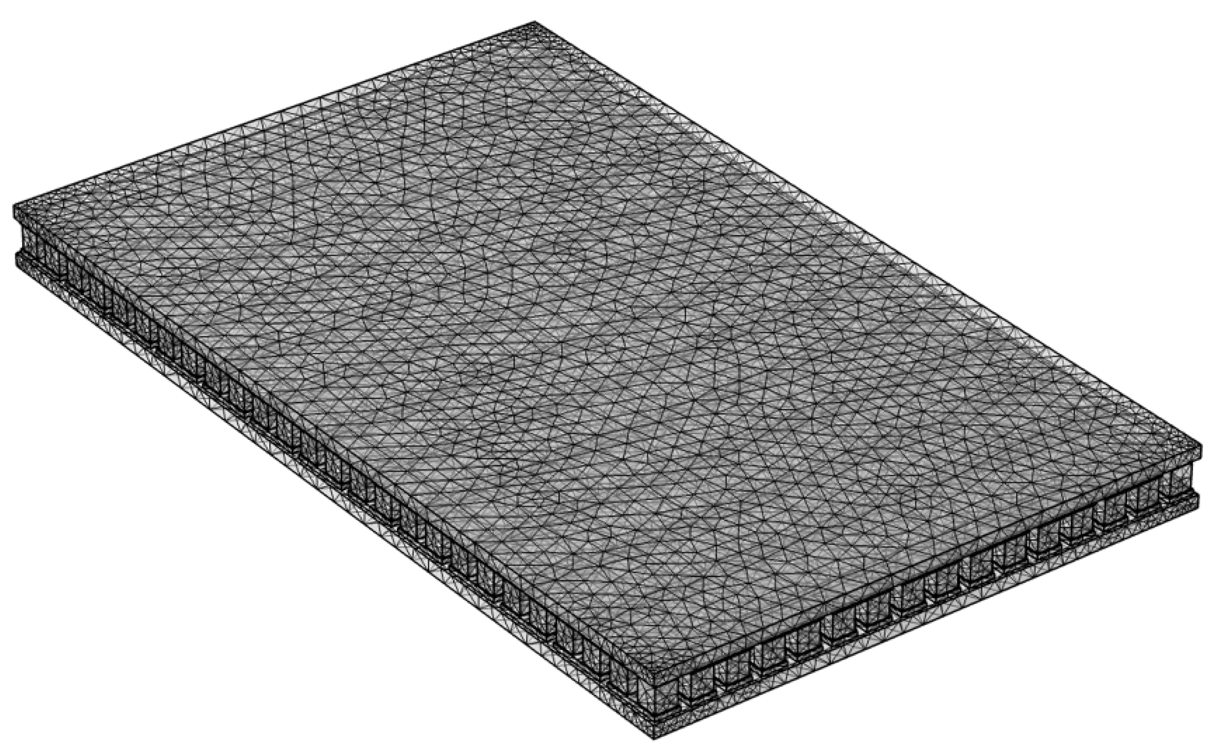
Figure 6.
Finite element network devision of the total system.
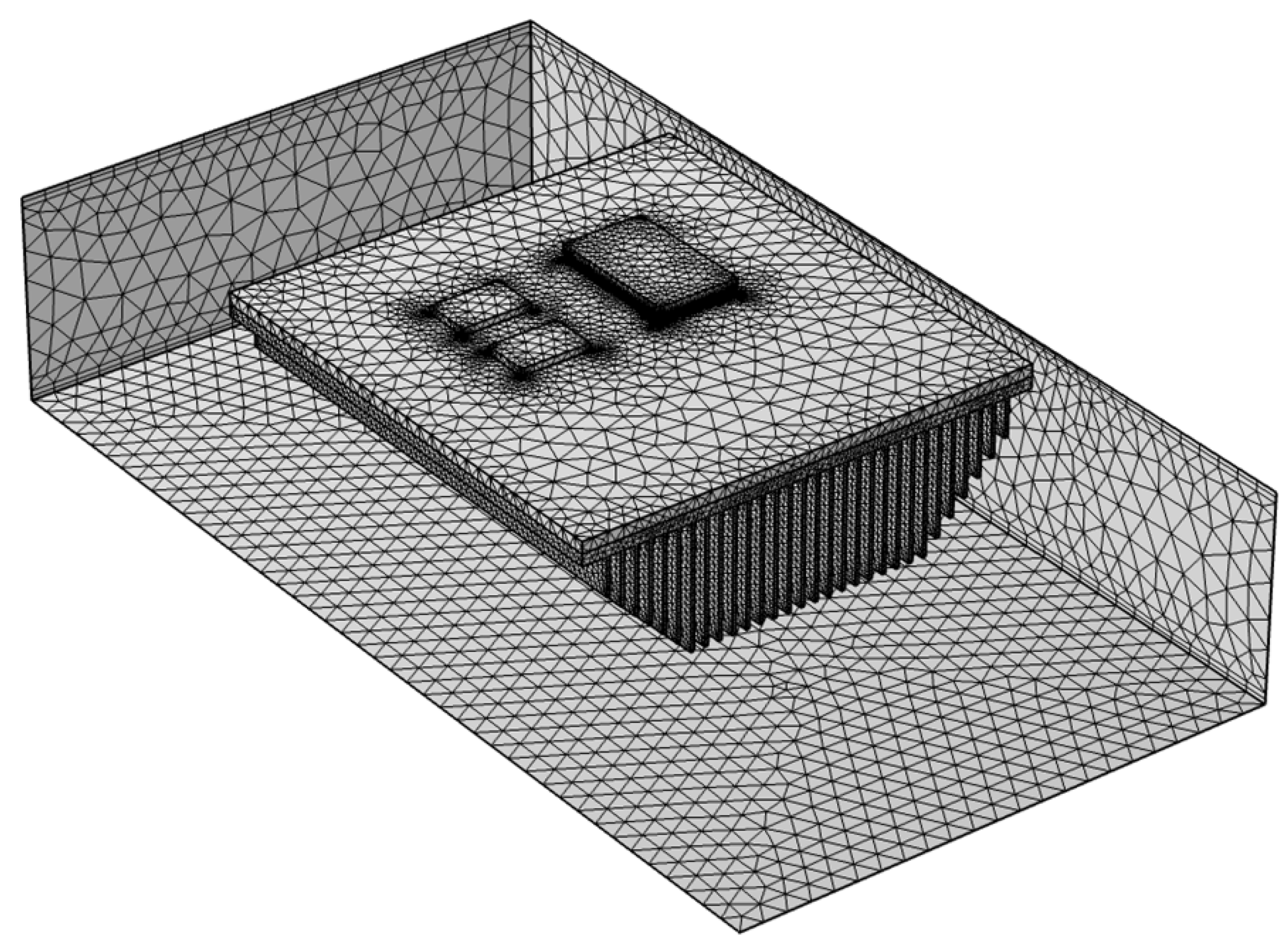
Figure 7.
Air flow velocity distribution in the air duct.
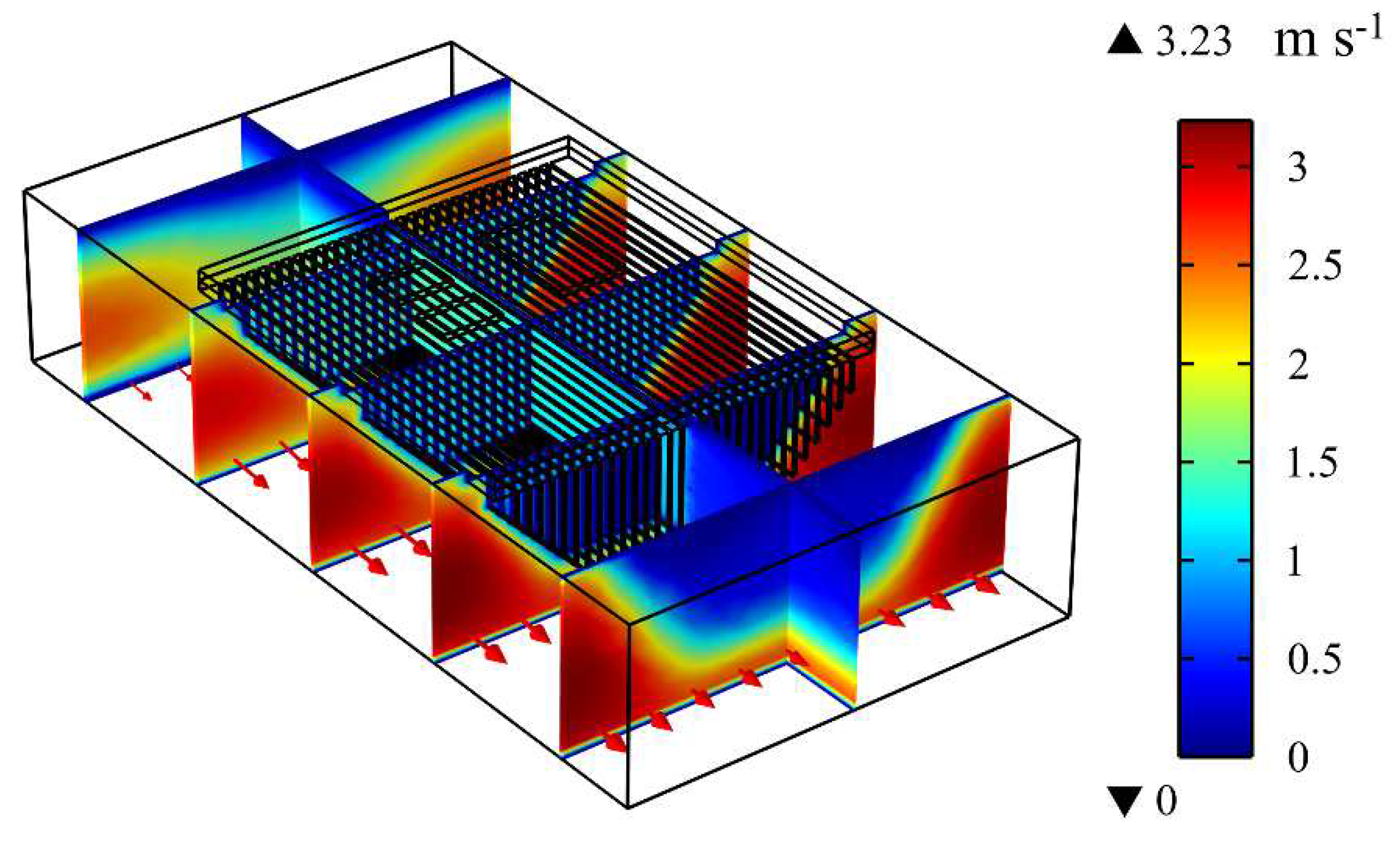
Figure 8.
Temperature distribution under air cooling: (a) the overall system, (b) the high power consumption power devices, (c) the low power consumption power devices, and (d) the heat sink fins.
Figure 8.
Temperature distribution under air cooling: (a) the overall system, (b) the high power consumption power devices, (c) the low power consumption power devices, and (d) the heat sink fins.
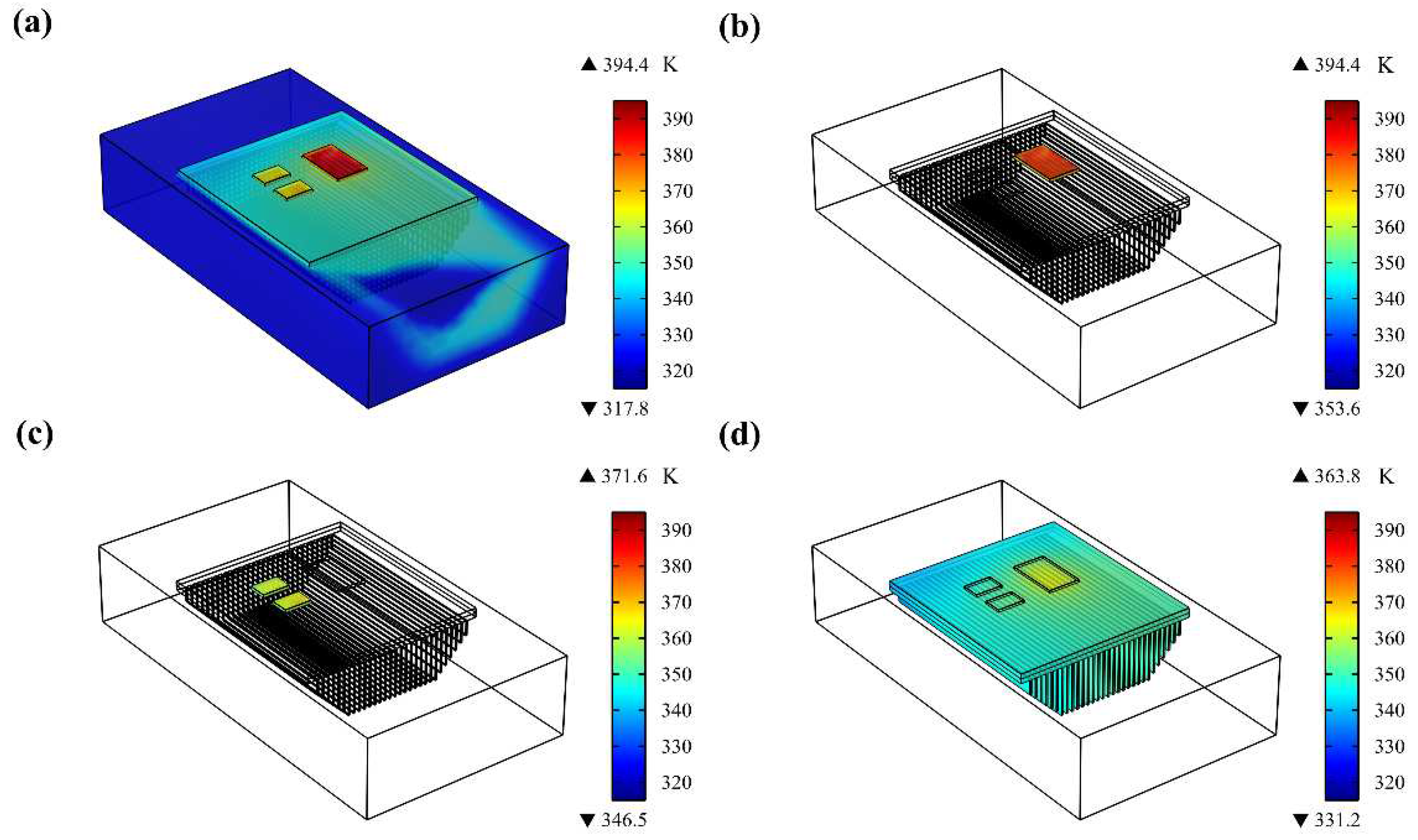
Figure 9.
Temperature distribution under TEC forced cooling and air cooling: (a) the overall system, (b) the high power consumption power devices, (c) the low power consumption power devices, and (d) the heat sink fins.
Figure 9.
Temperature distribution under TEC forced cooling and air cooling: (a) the overall system, (b) the high power consumption power devices, (c) the low power consumption power devices, and (d) the heat sink fins.
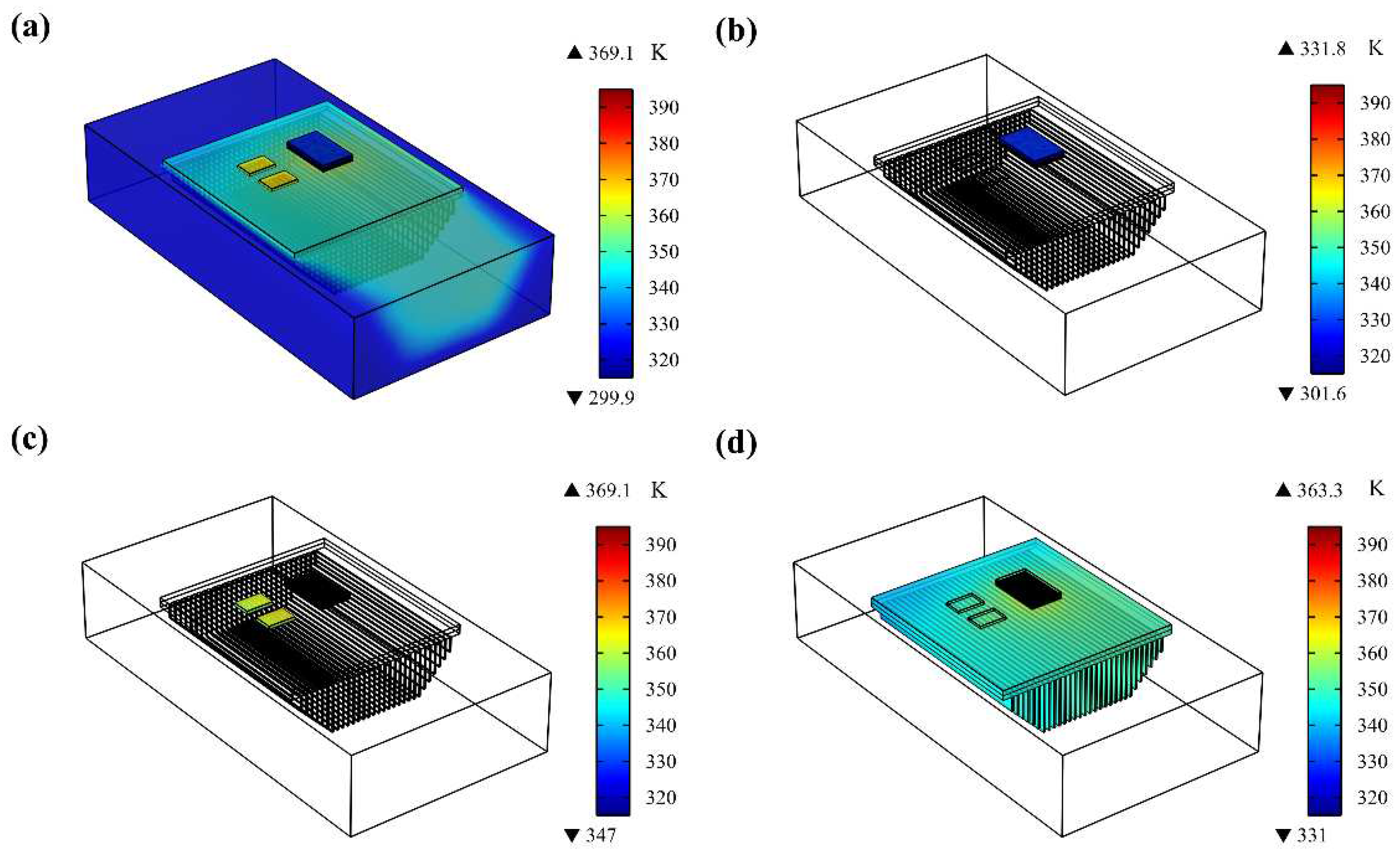
Figure 10.
Influence of TEC working current on the average temperature of: (a) the high power consumption power devices, (b) the low power consumption power devices, (c) the heat sink fins.
Figure 10.
Influence of TEC working current on the average temperature of: (a) the high power consumption power devices, (b) the low power consumption power devices, (c) the heat sink fins.
Disclaimer/Publisher’s Note: The statements, opinions and data contained in all publications are solely those of the individual author(s) and contributor(s) and not of MDPI and/or the editor(s). MDPI and/or the editor(s) disclaim responsibility for any injury to people or property resulting from any ideas, methods, instructions or products referred to in the content. |
© 2023 by the authors. Licensee MDPI, Basel, Switzerland. This article is an open access article distributed under the terms and conditions of the Creative Commons Attribution (CC BY) license (http://creativecommons.org/licenses/by/4.0/).
Copyright: This open access article is published under a Creative Commons CC BY 4.0 license, which permit the free download, distribution, and reuse, provided that the author and preprint are cited in any reuse.


