
Submitted:
23 April 2023
Posted:
24 April 2023
You are already at the latest version
Abstract
The shield tunnels inevitably endure various damage with the service time increasing. Meanwhile, steel corrugated plate has been used extensively in multiple conditions and proved effective to strengthen the segmental joints by full-scale tests. A numerical model is proposed to probe the feasibility of using new Stainless Steel Corrugated Plate (SSCP) to reinforce the shield tunnel segments. A new method, called virtual tracking element technology, is employed to achieve the simulation of realistic stress state of the segmental joint. Moreover, the segmental joint component analysis and parametric study are conducted based on the numerical model. The results demonstrate that: (1) the virtual tracking element technology proves valid and efficient to simulate the secondary stress state of segmental joint; (2) SSCP reinforcement is not fully utilized when the grade of segmental concrete is C50 and it has abundant safety margin for potential overload; (3) SSCP reinforcement is well-performed regardless of the burial depth and reinforcement in advance is recommended.
Keywords:
numerical analysis
; virtual tracking element
; segmental joints
; stainless steel corrugated plate
; tunnel reinforcement
1. Introduction
As the service time of the shield tunnels increases, it is common for segments to have deficiencies such as seepage, cracking and spalling [1,2,3], leading to large lateral deformation and lower bearing capacity of tunnels, which poses potential threat to the operation and maintenance. It is necessary to repair and strengthen the existing shield tunnel segments.
A variety of reinforcement technologies have been applied to shield segment reinforcement, such as steel plate-UHPC composite structure [4], steel plate-short bolt composite structure [5], filament wound profiles (FWP) [6], ultra-high toughness cementitious composite [7], etc. However, existing reinforcement technologies have limitations such as complex procedures, large steel consumption, and limited reinforcement effects. The new stainless steel corrugated plate (SSCP) has many advantages in the field of tunnel segment reinforcement due to its novel structure, light weight, high strength, convenient construction and corrosion resistance [8].
Corrugated steel has been widely used in pipelines, culverts and utility tunnels [9,10,11,12]. When it comes to the construction of tunnels, the corrugated steel plate has been used as support structure and proved to be capable of resisting the surrounding rock deformation [13]. In addition, attempts have been made in the corrugated steel plate strengthening shield tunnels. Ren [14] investigated the ultimate bearing capacity and failure mode of the corrugated steel reinforced segment through a mechanical test but the tunnel segmental joint is not considered. A full-scale test (details are introduced in Section 2) was carried out to investigate the mechanical behaviors of the segmental joint, unreinforced and reinforced by stainless steel corrugated plate (SSCP), and the latter manifests higher strength and stiffness, a longer hardening phase and better ductility.
Full-scale mechanical tests can reflect the mechanical properties of the specimen with high precision, but there are problems such as high cost and the loading conditions are limited and not entirely representative. Numerical model can simulate various working conditions with low cost, but the model needs to be calibrated by the mechanical test. To investigate the effect of segmental joint reinforcement, numerical methods have been developed, which usually establish refined model of the segmental joint comprising grooves, bolt hand holes, gaskets, etc. Simultaneously, in order to improve the efficiency, reasonable simplification of the constitutive model and contact relationship is taken into account.
In numerical analysis, removing and activating elements is generally used to realize the simulation of the secondary stress process of reinforcement [15]. Elements of reinforcement components (such as reinforced steel plates, interface, etc.) are removed before the calculation starts, and activated after deformation is generated by applying loads on the original structure. Although this method is theoretically feasible, the activated element often appears at the initial position, resulting in the overlap with the deformed structure, which is not consistent with the reality [6,16,17]. Therefore, a new method, called virtual tracking element technology [18], is adopted to let the reinforcement element deform along with the structure but have no impact on the stress or strain. Hence the reinforcement element can be activated at deformed place and bear the load normally with the damaged structure, realizing the secondary stress simulation.
This paper is organized as follows: Section 2 contains the experimental data from the full-scale test of segmental joint reinforced by SSCP. Section 3 is devoted to the development method and parameters of the numerical modeling. Section 4 introduces the principle and methodology of using virtual tracking element technology to simulate secondary stress state. Section 5 is meant to verify the validity of the numerical model and analyze the numerical results and parametric study.
2. Data from the full-scale test
The experiment included two full-scale segmental joint specimens designated as SP-0 and SP-1, referred to the unreinforced and reinforced segmental joint specimen, representing a typical joint configuration in subway shield tunnel lining structures.
Both specimens are assembled by two segments with a central angle of 23°. The intrados and extrados diameters of the segments was 5500 mm and 6200 mm, and the width and thickness of the segments was 1200 mm and 350 mm, respectively. Two 5.8-grade M30 bent bolts (center line arc radius 380mm, arc length 530mm) were used to assemble the segments to form the joint specimen.
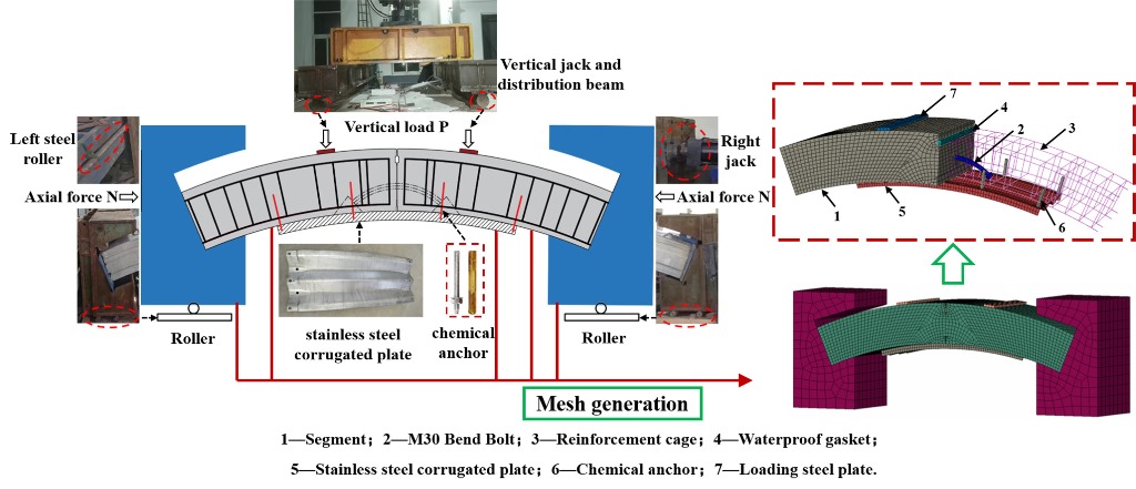
Figure 1 shows the stainless steel corrugated plate (SSCP) reinforced segmental joint specimen (SP-1). The segments and bent bolts used in the strengthened segmental joint specimen were the same as those used in the unreinforced segmental joint specimen. Chemical anchors made of 2205 stainless steel with a diameter of 16mm were used to fix SSCP on the segmental joint, and holes with a diameter of 20mm were punched on SSCP. The ends of the joint specimens were erected on two steel components and the bottom of them were supported by two rollers, which means they were simply supported. No preload was applied to the unreinforced specimens (SP-0).
The segmental joints of tunnels in service have been under stress before reinforcement, and reinforcement will not bear load until the load continues to develop or segmental material degrades. Therefore, the joint is actually in the secondary stress state when the reinforcement starts to share the load. In order to simulate the realistic reinforcement condition, in the full-scale test, the secondary stress state of the specimen is achieved by applying a vertical load Fk, corresponding to the load of the elastic deformation limit point of unreinforced specimen (SP-0), on the segmental joint before reinforcement. When the load was lower than Fk, the nut of chemical anchor, which connects the specimen (SP-1) and SSCP, was not tightened, hence SSCP would not share the load borne by the specimen. In other words, the reinforcement was applied by tightening the chemical anchor bolt nut when the load reached Fk (see Figure 2).
3. Numerical Modelling
3.1. Geometry and Element Mesh
The numerical model is made up of the following components: the segment, corrugated steel plate, chemical anchor, reinforcement cage, bent bolt, loading plate and support. Except that the longitudinal width of the segment is taken as half the structure is 600mm, the size of other components is the same as the test.
The element type of the components except rebars is the eight-node solid reduced integral element, referring to as C3D8R in ABAQUS, and the reinforcement cage uses the truss element.
3.2. Constitutive Models of Materials
A simplified elastoplastic tri-fold constitutive curve is adopted to model the concrete (Figure 3a). The waterproof gasket is generally considered as elastic in the FE model, in which the elastic modulus E is 1GPa and Poisson's ratio ν is 0.45. The material of the corrugated steel plate used in the test is a new type of duplex stainless steel S32001 (Figure 3b). The bent bolts, chemical anchors, rebars, backing plates and supports are modelled by a double-slash elastic-plastic model (Figure 3c). The detailed parameters of the materials are listed in Table 1.
3.3. Contact Relationships
The hard contact can transmit any pressure until the two components are separated and penetration would not occur. Tied constraint means that the contact surfaces are firmly bonded and separation is not allowed, as the segment, the support, and the backing plate are kept in close contact during the loading process and the connection between the groove and the gasket is firm since they are pasted with glue. The embedded region is extensively used to simulate the contact between the concrete and rebars since it allows overlap between the parts without deducting space. The contact relationships in the model are summarized in Table 2 and demonstrated in Figure 4.
3.4. Load and Boundary Conditions
In the mechanical test, the vertical force provided by the actuator acts on the two loading plates on the top of the segment through the distribution beam, and the horizontal force acts directly on the support through the horizontal actuator. In the FE model, reference points corresponding to the acting surface of the actuators are created, and the concentrated loads are applied on them.
The round steel rod at the bottom and left side limits the vertical and horizontal displacement of the specimen, respectively. Constraints are imposed at the corresponding positions. The 3D FE model is as illustrated in Figure 4
4. Secondary Stress Simulation
4.1. Principle of Virtual Tracking Element Technology
ABAQUS can realize the removal (Deactivated) and activation (Reactivated) of the element. During the simulation of the reinforcement installation, the position of the segmental joint changes after the initial load is applied. However, in ABAQUS the activation of the corresponding element is activated at the original position, resulting in the activated reinforcement element partially overlaps the deformed joint, which is inconsistent with the reality.
In order to simulate the realistic reinforcement under secondary stress state, the activated element needs to appear in the deformed position without strain, so as to bear the load normally after reinforcement. The original element (abbreviated as OE), which is element of SSCP and chemical anchor in this model, needs to be copied as element with tracking function (called virtual tracking element, abbreviated as VE) at the same location, i.e., VE is actually a backup of OE, with exactly the same nodes. Moreover, VE is required to have no influence on the original structure, thus the position of VE can be obtained along with the deformation of the structure. When OE is activated, its elements are generated at the deformed position as they have the same nodes as VE. Then OE shares the load with the deformed structure as the loading continues. Considering the above principle, the requirements for VE are summarized as follows:
- VE should have the same shape and contact relationship as OE, share all nodes but have a different element number;
- The stiffness of VE should be extremely small, so that its influence on the stress of the original structure can be ignored;
- The mass of VE should be especially small to prevent potential displacement caused by the weight.
4.2. Simulation Methodology
Based on the principle of virtual tracking element, the secondary stress simulation of the segmental joint reinforcement can be realized. The methodology of virtual tracking element technology in ABAQUS can be divided into following steps:
Specifically, the method to creating VE is: Export the model file, and use the "Elcopy" command to copy the corresponding original element, then import the modified model file and set the properties of VE. Notably, the elastic modulus should be set 4 to 5 orders of magnitude smaller than the original structure, the density can be set as 0 and contact relationship need not to be reset since it is the same as OE.
5. Result and Analysis
5.1. Model Validation
In order to verify the validity of the numerical model, the comparison between the numerical calculation results and the experimental results is carried out, and the corresponding results of unreinforced and reinforced specimen is shown in Figure 6 and Figure 7. It can be seen that both numerical curves are in good agreement with the experimental results, and the curve can be divided into a couple of sections, respectively.
As is demonstrated in Figure 6, in the oa section, the specimen is in elastic stage, with small deformation and high stiffness, which is slightly larger than the test result due to the manufacturing errors in the experiment. The deformation accelerates in the ab section since the bent bolts begin to yield. In the bc section, a temporary increase of the stiffness occurs since the extrados concrete is squeezed and in close contact; in the ultimate failure stage (cd section), the compression stress exceeds the bearing capacity of the concrete and leads to the failure, and the ultimate moment is 193kN∙m.
When it comes to the reinforced specimen (Figure 7), the point a is the reinforcement point, corresponding to the elastic limit (point a in Figure 6), and the stiffness in the oa section is the same as the unreinforced specimen, indicating the virtual tracking element has no effect on the specimen. The ab section manifests similar stiffness with the unreinforced specimen, which is attributed to the interspace between the punched hole wall of SSCP and chemical anchor, making SSCP unable to share the load. When the chemical anchor contacts the hole wall (point b), the stiffness has a notable increase due to the high reinforcement capability of SSCP. Therefore, the increase of stiffness often lags behind the reinforcement point. In the cd section, the stiffness gradually decreases because the trough of SSCP enters into the yielding stage, which undermines its capacity of resisting deformation. In the final stage, the failure mode is the same as the unreinforced specimen (concrete cracked), and the ultimate moment is 464kN∙m, which increases by 140.4% compared to the unreinforced specimen.
5.2. Component Analysis
5.2.1. Bent bolt
The stress contour and deformation of the bent bolts of the unreinforced specimen are shown in Figure 8a. The intrados surface begins to yield (Mises stress exceeds 400MPa) when the moment increases to 113kN∙m, and the deformation grows quickly after yielding. When the moment reaches 193kN∙m, most part the bent bolt enters plastic stage but only limited region (the mid-span intrados) reaches the ultimate stress (500MPa).
As is shown in Figure 8b, with the SSCP sharing the load, the stress and deformation of the bent bolt is relatively lower under the same moment (M=87kN∙m). Moreover, the ultimate moment is obviously increased (464kN∙m) and the stress in the ultimate stage is higher. Nearly the whole bolt yields and the midrange reaches the ultimate stress, resulting in considerably larger deformation (543mm) than that of the unreinforced specimen (516mm).
5.2.2. Stainless Steel Corrugated Plate (SSCP)
Figure 9 is the stress contour of the SSCP at different stages. When the moment increases to 288kN∙m, the stress of the trough and side plate partially reaches the yield stress (490 MPa), leading to the decrease of the stiffness of the reinforced specimen. When the specimen comes to the ultimate stage (concrete cracking), no SSCP buckling happens and the maximum stress (605MPa) is far from reaching the ultimate strength(720 MPa), interpreting that the reinforcement capacity of SSCP is not fully utilized when the grade of concrete is C50. On the other hand, the relatively low utilization means adequate safety margin for unexpected conditions.
5.2.3 Chemical Anchor
As can be seen from Figure 10, the chemical anchor is under shear stress. When moment reaches 288kN∙m, there is a localized region of high stress at the joint between the chemical anchor and the hole wall of the SSCP, and the anchor shows obvious bending shear behavior. When the specimen enters into ultimate failure stage (moment reaches 464kN∙m), the lower part of the anchor yields (Mises stress is larger than 640MPa) and the joint region reaches the ultimate stress (800MPa). Nevertheless, no shear failure occurs during the loading process, owing to the superior ductility of the chemical anchor.
5.3. Parametric Study
5.3.1. Axial Force
According to the different burial depths of tunnels in Shanghai metro, the axial force is divided into three conditions: 600kN, 1000kN, and 1400kN, corresponding to three burial depth types: shallow burial, medium burial and deep burial, respectively (see Figure 11). With the axial force increasing, the stiffness in the initial stage is higher due to the closer contact of the extrados concrete. Nevertheless, the slope of the curves is basically the same in the ultimate stage. The underlying cause is that the stiffness is all provided by SCCP since the concrete has almost completely cracked at this time. In other words, the strength of SSCP is high enough to make sure the SSCP can sustain its reinforcement effect until the concrete failure under different axial forces, which indicates the extensive applicability of SSCP reinforcement in tunnels with different burial depths.
5.3.2 Reinforcement Timing
The reinforcement is conducted when the load reaches 1.0Fk (corresponding to the elastic limit point) in the full-scale test, and the ultimate load of the unreinforced specimen is 2.2Fk. In order to investigate the appropriate reinforcement opportunity, different reinforcement timings are considered by activating reinforcement element under different loads: 1.0Fk, 1.4Fk, 1.8Fk and no pre-applied load (see Figure 12). There is no obvious improvement of the ultimate bending moment, and the ultimate rotational angles are also basically the same, indicating that the utilization of SSCP is comparable. Although the stiffness is similar in the ultimate stage, the increase in initial stiffness is more evident with the advance of reinforcement. Considering the tunnels in service are typically in elastic or elastoplastic stage, reinforcement in advance is recommended.
6. Conclusions
In this paper, the finite element software ABAQUS is used to establish a numerical model of the new SSCP reinforcement for the segmental joints of the shield tunnel, and the virtual tracking element is used to realize the secondary stress simulation of the segmental joint. The validity of the numerical model is confirmed by the full-scale test. The main conclusions are as follows:
- The virtual tracking element technology is feasible to simulate the secondary stress state of segmental joint reinforcement. The virtual tracking element is similar to a backup of the original element, and it has no influence on the stress and strain as the structure deforms. By removing and activating the corresponding elements at different steps, the existing deformation and secondary stress characteristics of the segmental joint can be taken into account.
- The reinforcement capacity of SSCP is not fully utilized when segmental concrete is C50 grade. Hence SSCP utilization is higher when reinforcing segmental joint of high-grade concrete. On the other hand, the relatively low utilization indicates that SSCP reinforcement has sufficient safety margin for potential excessive load.
- SSCP can sustain its reinforcement capability under different axial forces, thus SSCP is applicable to tunnel reinforcement regardless of the burial depth. In addition, reinforcement in advance is recommended since the increase in stiffness is relatively more obvious when the tunnel is in elastic or elastoplastic stage.
Author Contributions
W.D.: conceptualization, methodology, funding acquisition. C.M.: writing, data analysis. Y.G.: writing, problem modelling. X.L: methodology, problem modelling. S.L.: review, editing. All authors have read and agreed to the published version of the manuscript.
Funding
This research was funded by Shanghai 2020 “Science and Technology Innovation Action Plan” Project (No. 20dz1202600), Yunnan 2022 “Science and Technology Innovation and Demonstration” Project (No. 2022-25), NSFC (No. 52090083), and National Key R&D Program of China (No. 2021YFC3002004).
Institutional Review Board Statement
Not applicable.
Informed Consent Statement
Not applicable.
Data Availability Statement
Not applicable.
Acknowledgments
The authors thank the managers of the Shanghai Huaxia Corrugated Steel Research Institute and Research Institute of Tsingtuo Group for their help with this study.
Conflicts of Interest
The authors declare no conflict of interest.
References
- Ding, W.; Chen, X.; Jin, Y.; Qiao, Y. Flexural behavior of segmental joint containing double rows of bolts: Experiment and simulation. Tunn. Undergr. Space Technol. 2021, 112. [Google Scholar] [CrossRef]
- Jin, H.; Yuan, D.; Zhou, S.; Zhao, D. Short-term and long-term displacement of surface and shield tunnel in soft soil: Field observations and numerical modeling. Appl. Sci. 2022, 12. [Google Scholar] [CrossRef]
- Lou, P.; Li, Y.; Xiao, H.; Zhang, Z.; Lu, S. Influence of small radius curve shield tunneling on settlement of ground surface and mechanical properties of surrounding rock and segment. Appl. Sci. 2022, 12. [Google Scholar] [CrossRef]
- Zhang, J.-L.; Liu, X.; Ren, T.-Y.; Yuan, Y.; Mang, H. A. Structural behavior of reinforced concrete segments of tunnel linings strengthened by a steel-concrete composite. Composites Part B 2019, 178. [Google Scholar] [CrossRef]
- Huang, G.; Gong, L.; Sun, X.; Liang, Z.-n.; Wang, X.-Y. Numerical investigation on flexural performance of retrofitted tunnel lining with short bolts and steel-plate. Tunn. Undergr. Space Technol. 2020, 95. [Google Scholar] [CrossRef]
- Liu, X.; Jiang, Z.; Yuan, Y.; Mang, H. A. Numerical investigation of the mechanical behavior of deformed segmental tunnel linings, strengthened by epoxy-bonded filament wound profiles. Tunn. Undergr. Space Technol. 2018, 78, 231–244. [Google Scholar] [CrossRef]
- Xu, S.; Mu, F.; Wang, J.; Li, W. Experimental study on the interfacial bonding behaviors between sprayed uhtcc and concrete substrate. Constr. Build. Mater. 2019, 195, 638–649. [Google Scholar] [CrossRef]
- Li, S.; Ding, W.; Zhang, Q.; Xiao, X.; Zhou, Q. Experimental study of the mechanical properties of a new duplex stainless steel exposed to elevated temperatures. Case Stud. Constr. Mater. 2022, 17. [Google Scholar] [CrossRef]
- Simpson, B.; Moore, I. D.; Hoult, N. A. Experimental investigation of rehabilitated steel culvert performance under static surface loading. J. Geotech. Geoenviron. Eng. 2016, 142. [Google Scholar] [CrossRef]
- Vaslestad, J.; Madaj, A.; Janusz, L. Field measurements of long-span corrugated steel culvert replacing corroded concrete bridge. Transportation research record 2002, 1814, 164–170. [Google Scholar] [CrossRef]
- Che, H.; Tong, L.; Liu, S.; Yang, Q. Field investigation on the mechanical performance of corrugated steel utility tunnel (csut). J. Constr. Steel Res. 2021, 183. [Google Scholar] [CrossRef]
- Kang, J. S.; Davidson, J. S. Structural effects of concrete lining for concrete-lined corrugated steel pipes. Struct. Infrastruct. Eng. 2010, 1–11. [Google Scholar] [CrossRef]
- Xu, P.; Wei, Y.; Yang, Y.; Zhou, X. Application of fabricated corrugated steel plate in subway tunnel supporting structure. Case Stud. Constr. Mater. 2022, 17. [Google Scholar] [CrossRef]
- Ren T, Liu S, Liu X, Experimental study of bending capacity of shield tunnel lining segment strengthened by corrugated steel, Tunnel Construction 2019, 39, 317–323. 39.
- Luo, Y. Experiment and analysis of shield tunnel strengthened with concrete filled steel tubes, Guangzhou, South China University of Technology, 2019.
- Zhao, H.; Liu, X.; Bao, Y.; Yuan, Y.; Bai, Y. Simplified nonlinear simulation of shield tunnel lining reinforced by epoxy bonded steel plates. Tunn. Undergr. Space Technol. 2016, 51, 362–371. [Google Scholar] [CrossRef]
- Jiang, Y.; Wang, X.; Li, B.; Higashi, Y.; Taniguchi, K.; Ishida, K. Estimation of reinforcing effects of FRP-PCM method on degraded tunnel linings. Soils and Foundations 2017, 57, 327–340. [Google Scholar] [CrossRef]
- Wang, Y. Study on parameters of plate-short anchor assembly structure of repairing cracking lining, Chengdu, Southwest Jiaotong University, 2019.
Figure 1.
Schematic diagram of components in the reinforced specimen (unit: mm)
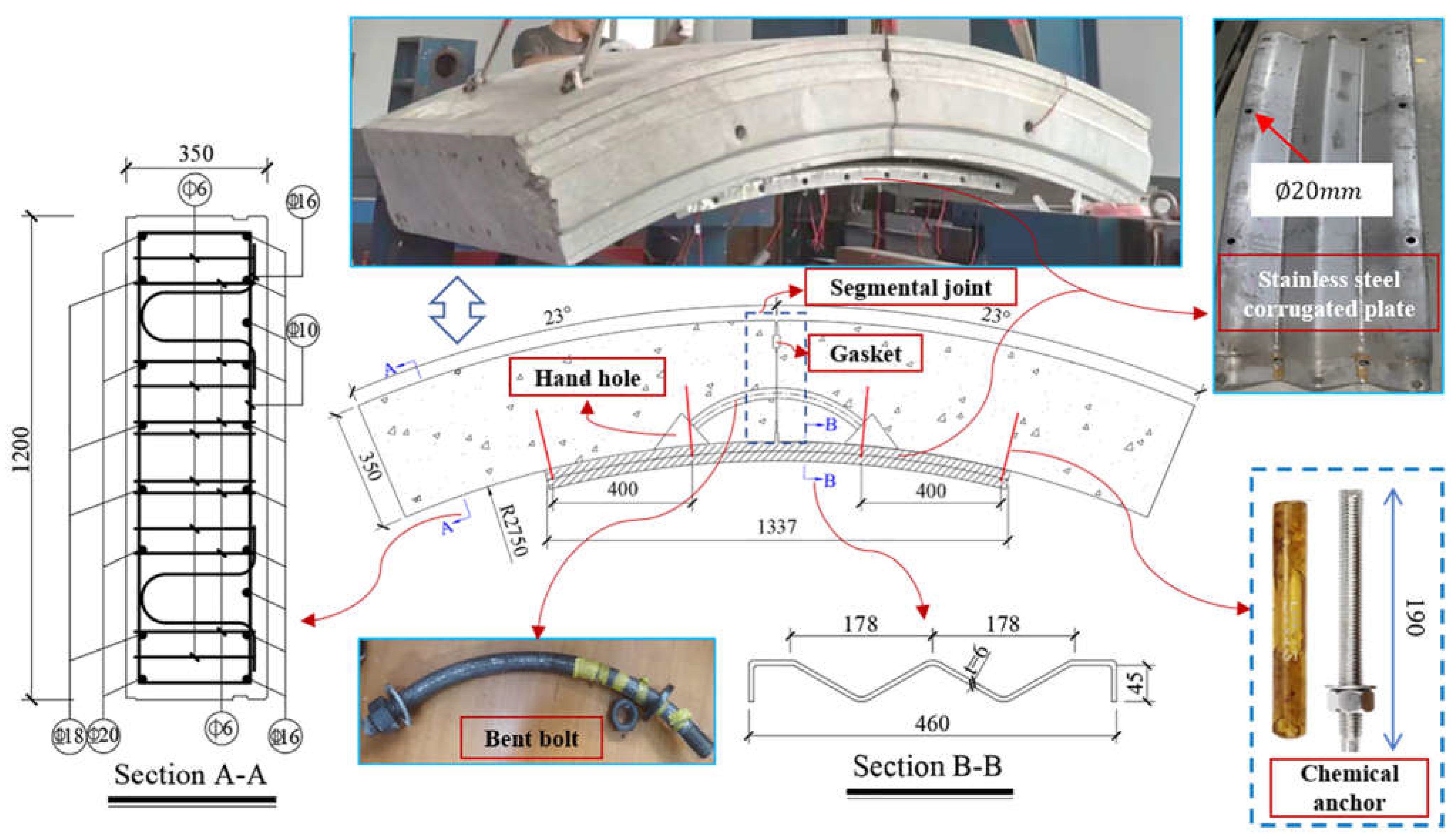
Figure 2.
Reinforcement installation in the full-scale test
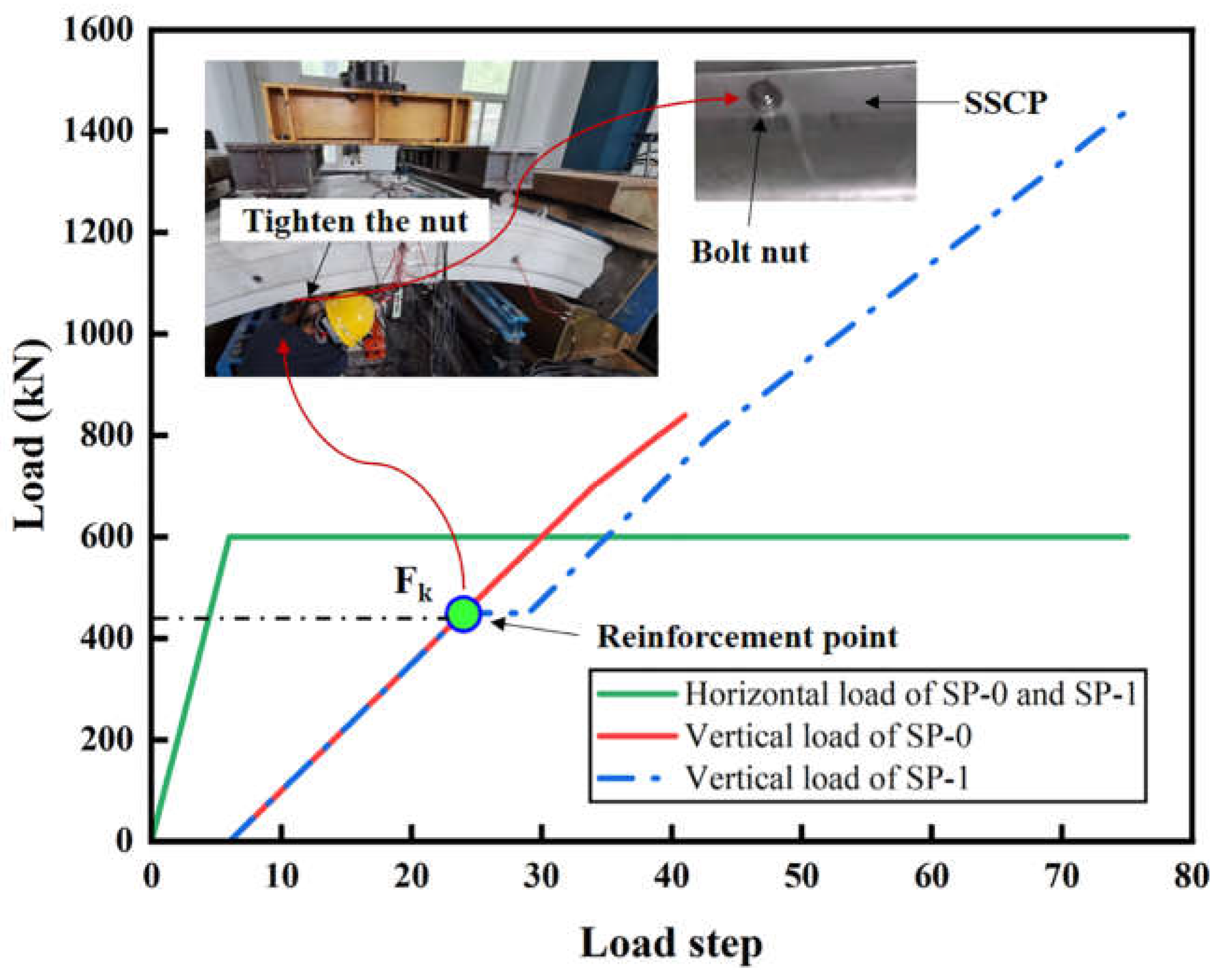
Figure 3.
Constitutive model of (a) segmental concrete; (b) stainless steel corrugated plate; (c) bent bolt, chemical anchor, reinforcement cage, backing plate and support.
Figure 3.
Constitutive model of (a) segmental concrete; (b) stainless steel corrugated plate; (c) bent bolt, chemical anchor, reinforcement cage, backing plate and support.
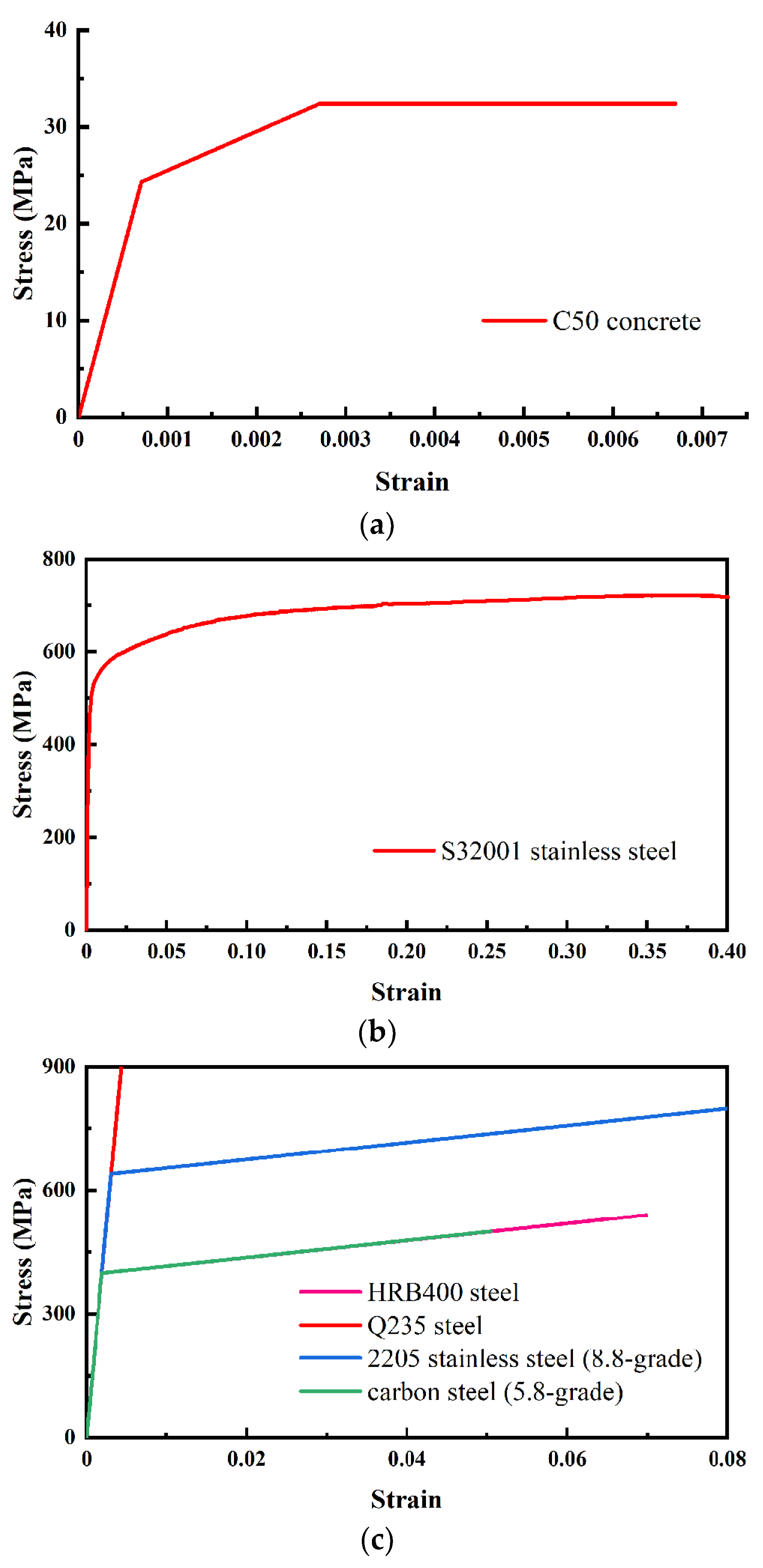
Figure 4.
Schematic diagram of contacts, loads and boundary conditions in the FE model
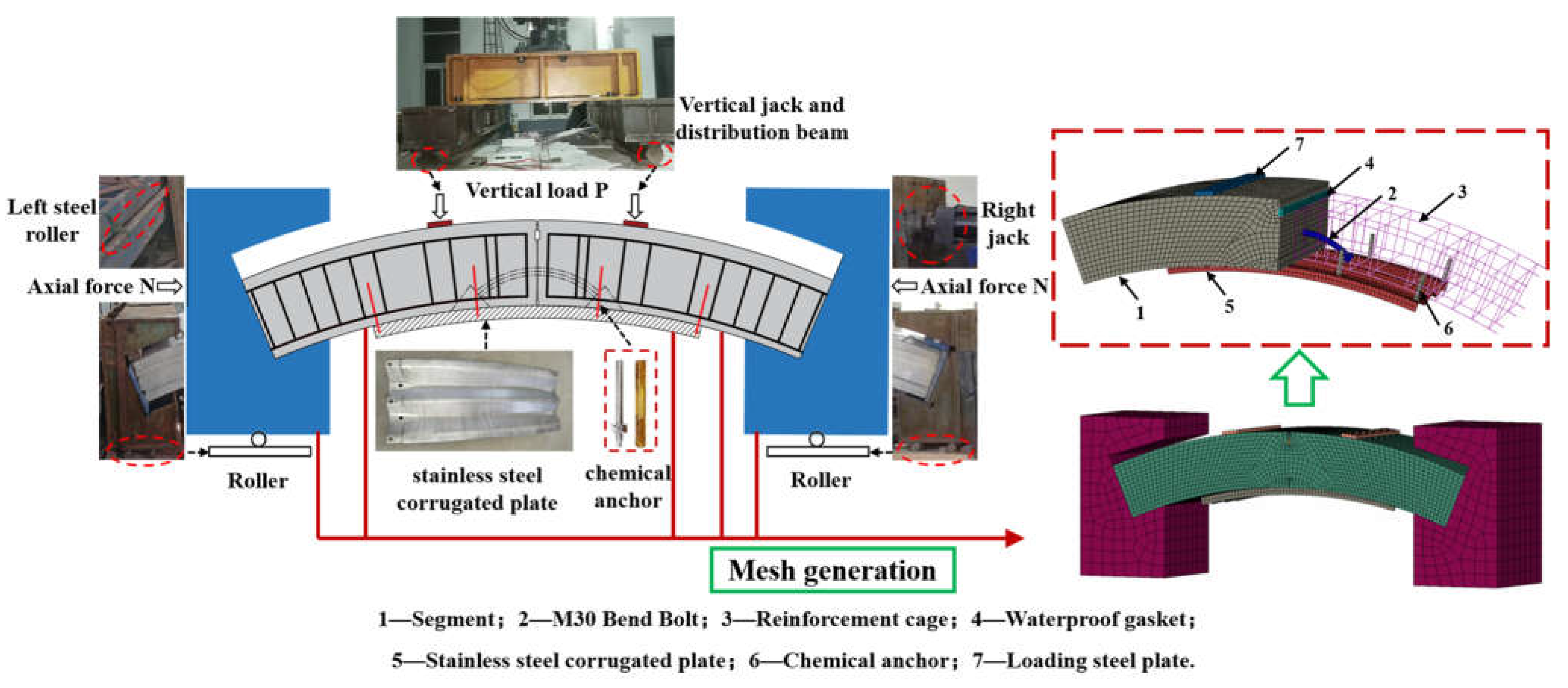
Figure 5.
Schematic diagram of virtual tracking element technology: (a) the initial model; (b) creation of VE; (c) removal of OE; (d) deformation of VE; (e) activation of OE; (f) continue of loading.
Figure 5.
Schematic diagram of virtual tracking element technology: (a) the initial model; (b) creation of VE; (c) removal of OE; (d) deformation of VE; (e) activation of OE; (f) continue of loading.
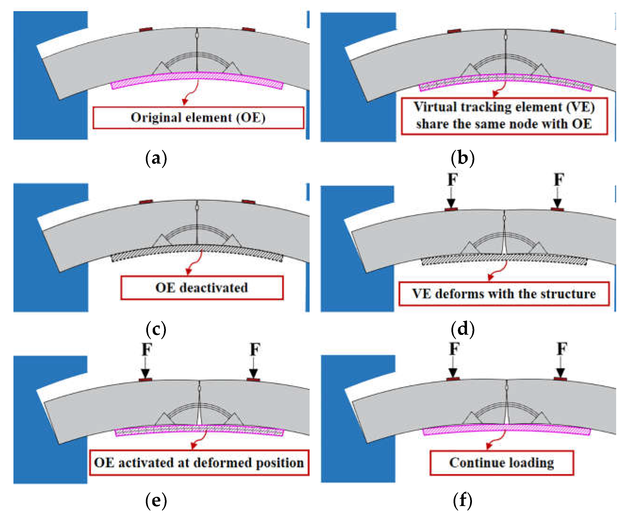
Figure 6.
Comparison between numerical and experimental results of the unreinforced specimen
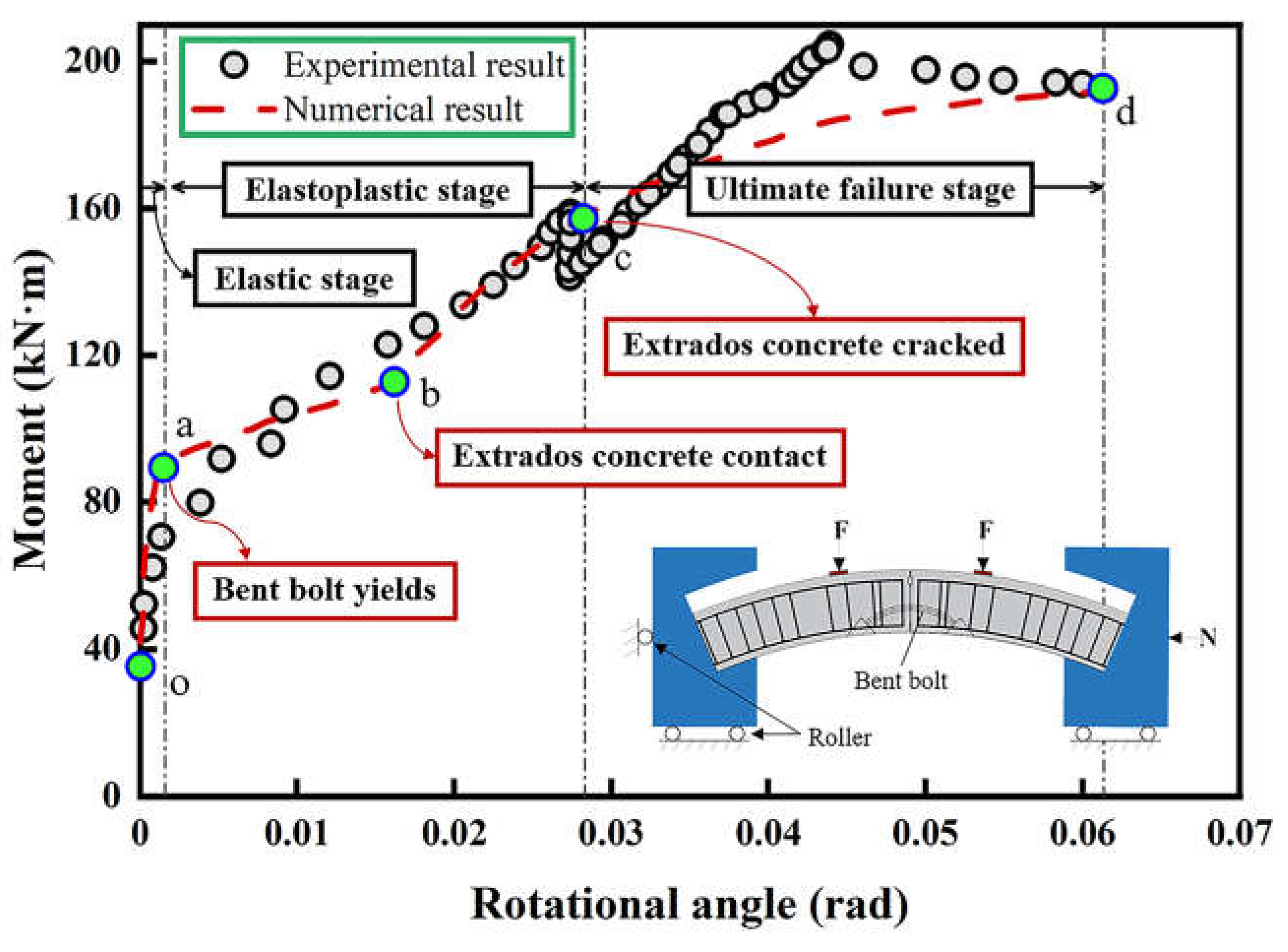
Figure 7.
Comparison between numerical and experimental results of the reinforced specimen
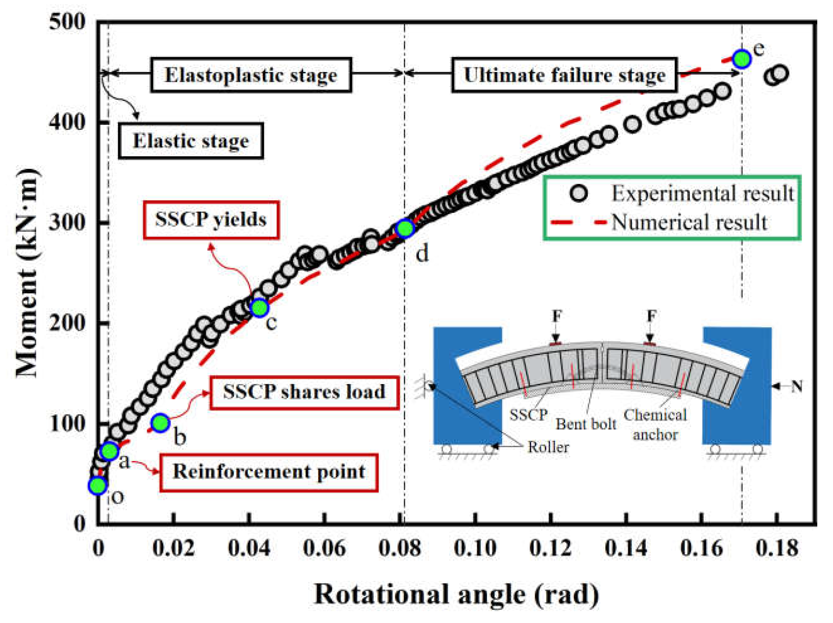
Figure 8.
Mises stress (Pa) and deformation results (mm) of bent bolts at different stages of (a) unreinforced specimen; (b) reinforced specimen.
Figure 8.
Mises stress (Pa) and deformation results (mm) of bent bolts at different stages of (a) unreinforced specimen; (b) reinforced specimen.
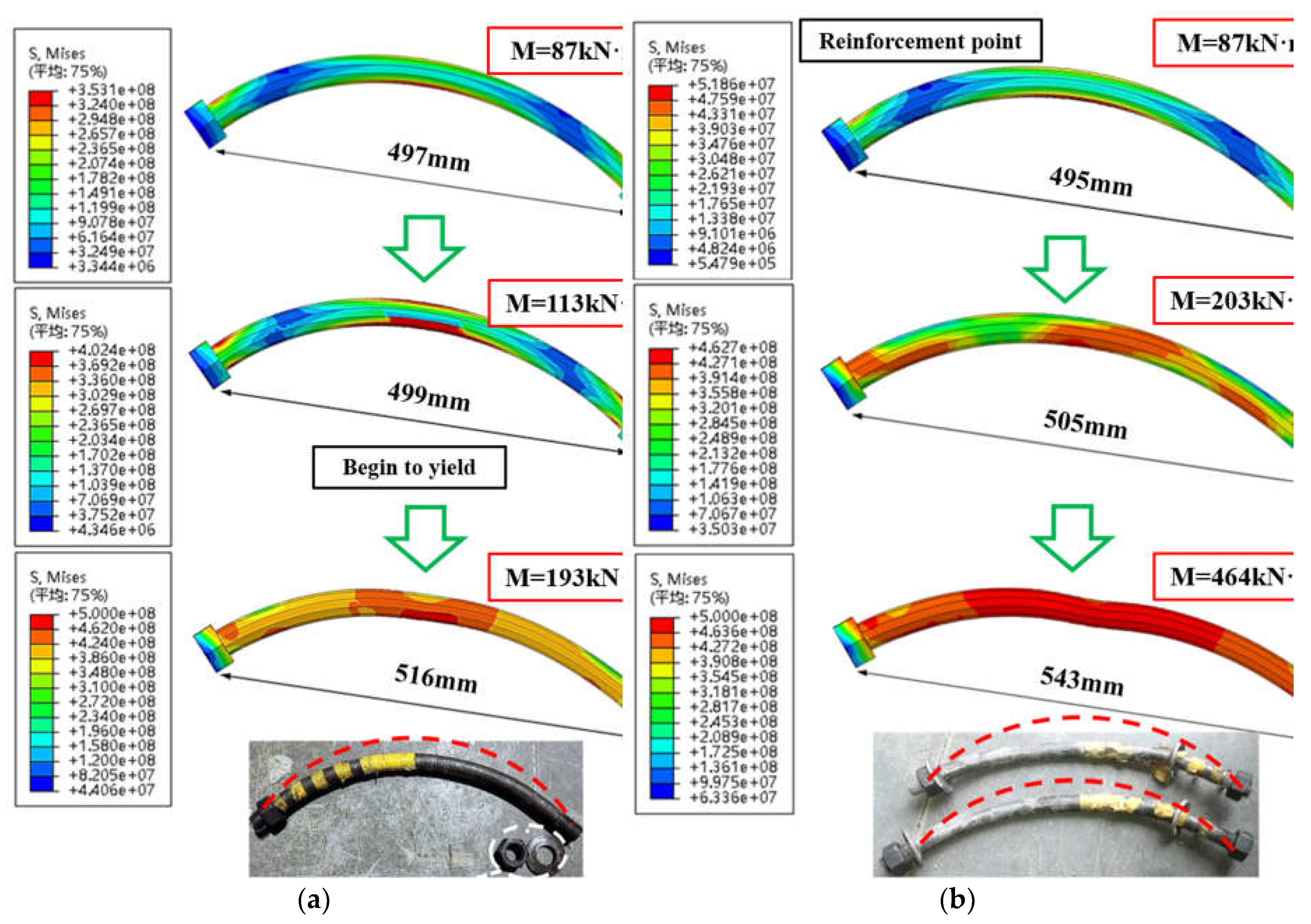
Figure 9.
Mises stress (Pa) of SSCP at different stages
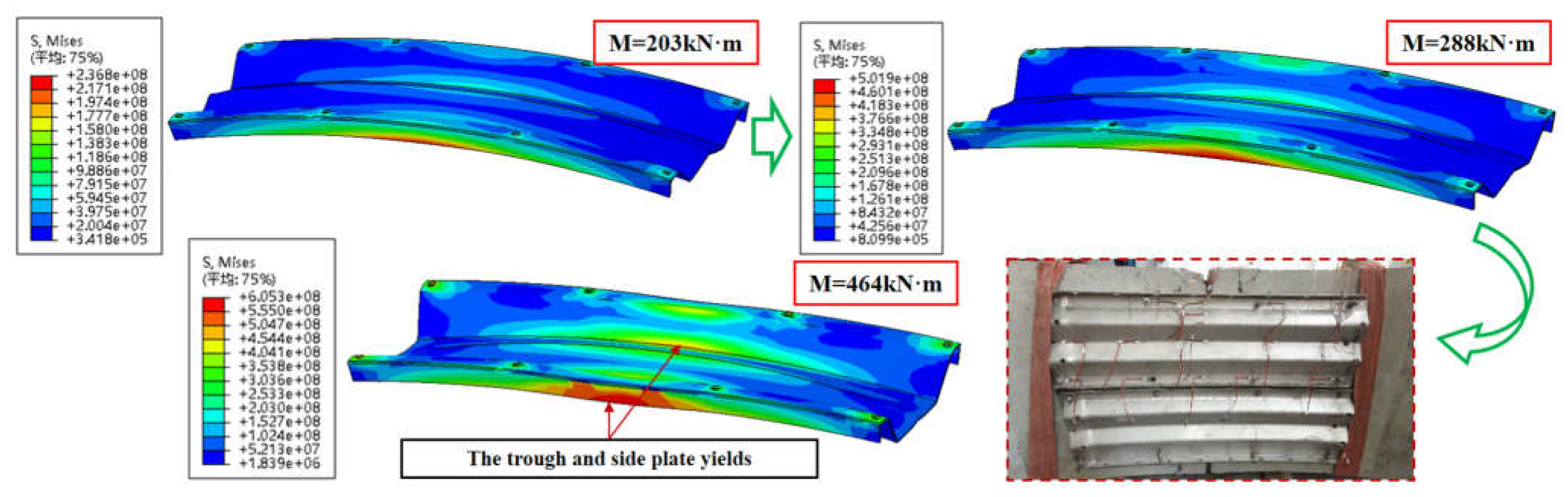
Figure 10.
Mises stress (Pa) of chemical anchors at different stages
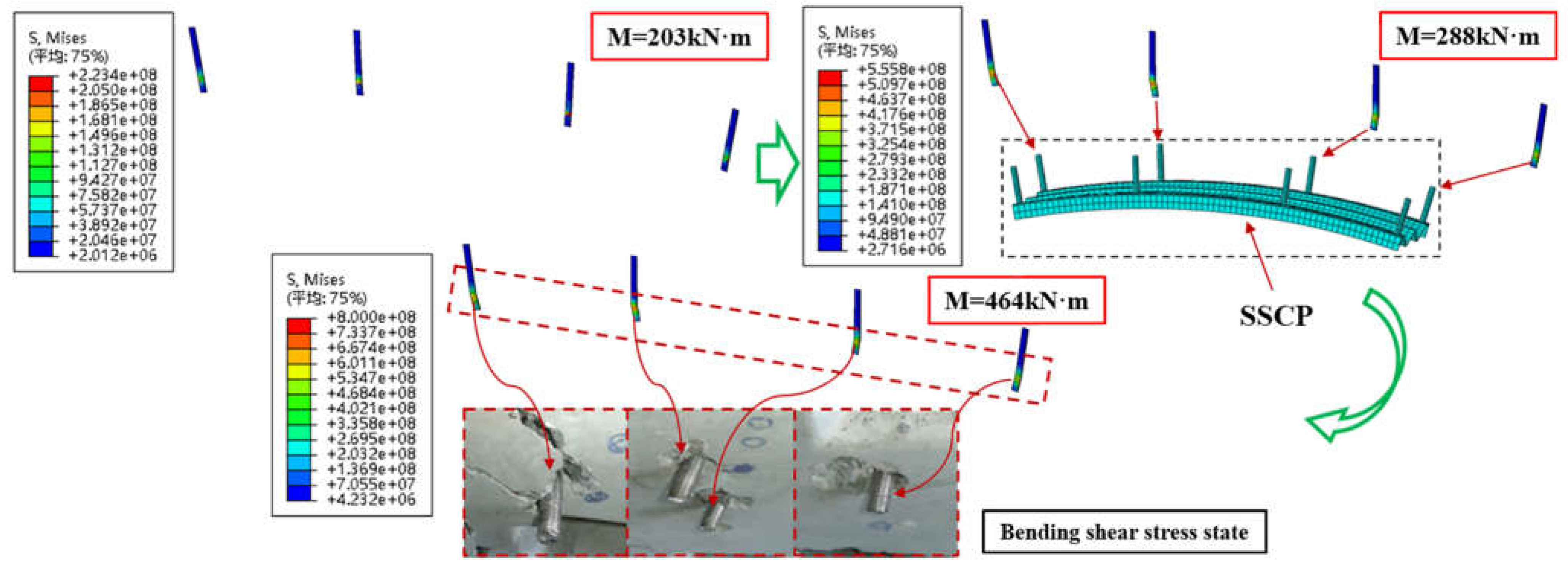
Figure 11.
Numerical results of bending moment-rotational angle curves of different axial forces.
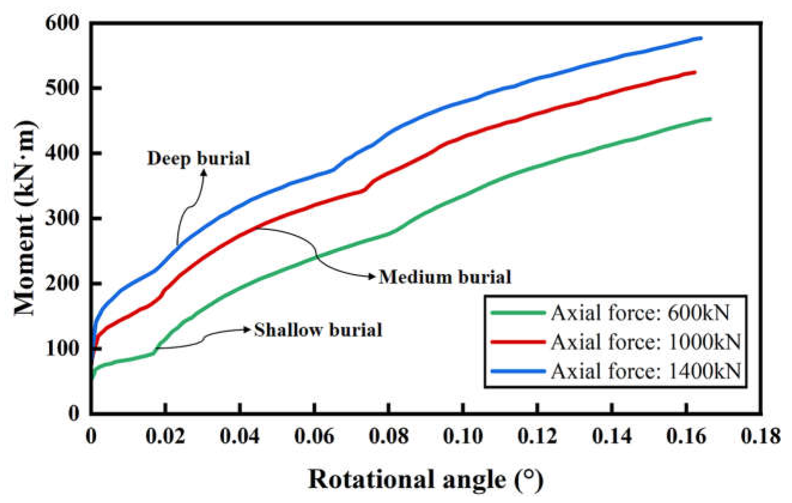
Figure 12.
Numerical results of bending moment-rotational angle curves of different reinforcement timings.
Figure 12.
Numerical results of bending moment-rotational angle curves of different reinforcement timings.
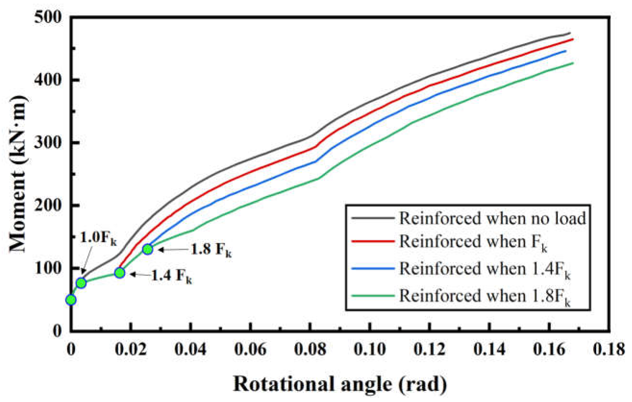

Table 1.
Materials parameters of the components
| Component | Material | E (GPa) | fy (MPa) | εy | fu (MPa) | ν |
|---|---|---|---|---|---|---|
| Bent Bolt | carbon steel (5.8-grade) | 206 | 400 | 0.0019 | 500 | 0.3 |
| Chemical Anchor | 2205 stainless steel (8.8-grade) | 206 | 640 | 0.0031 | 800 | 0.3 |
| Reinforcement cage | HRB400 steel | 206 | 400 | 0.0019 | 540 | 0.3 |
| Backing Plate | Q235 steel | 206 | — | — | — | 0.3 |
| Support | Q235 steel | 206 | — | — | — | 0.3 |
* E denotes the Elastic Modulus; fy denotes the yield stress; εy denotes the yield strain; fu denotes ultimate stress; ν denotes Poisson's ratio.
Table 2.
Contact types between components in the FE model
| Number | Contact pairs | Type |
|---|---|---|
| 1 | Segment and Segment | Hard contact |
| 2 | Segment and Reinforcement Cage | Embedded region |
| 3 | Segment bent bolts hole wall and bent bolts | Hard contact |
| 4 | Segment and Backing Plate | Tie |
| 5 | Segment and Support | Tie |
| 6 | Segment and Gasket | Tie |
| 7 | Segment hand hole face and bent bolt nut | Tie |
| 8 | Segment and Chemical Anchor | Embedded region |
| 9 | Segment and SSCP | Hard Contact |
| 10 | SSCP and Chemical Anchor | Tie |
| 11 | Gasket and Gasket | Hard Contact |
Disclaimer/Publisher’s Note: The statements, opinions and data contained in all publications are solely those of the individual author(s) and contributor(s) and not of MDPI and/or the editor(s). MDPI and/or the editor(s) disclaim responsibility for any injury to people or property resulting from any ideas, methods, instructions or products referred to in the content. |
© 2023 by the authors. Licensee MDPI, Basel, Switzerland. This article is an open access article distributed under the terms and conditions of the Creative Commons Attribution (CC BY) license (http://creativecommons.org/licenses/by/4.0/).
Copyright: This open access article is published under a Creative Commons CC BY 4.0 license, which permit the free download, distribution, and reuse, provided that the author and preprint are cited in any reuse.


