Submitted:
15 April 2023
Posted:
17 April 2023
You are already at the latest version
Abstract
Variable-DOF (or kinematotropic) mechanisms are a class of reconfigurable mechanisms. The number of variable-DOF multi-loop planar mechanisms proposed so far is very limited. This paper proposes a novel 8-link variable-DOF planar mechanism with five motion modes. Firstly, a description of the 8-link variable-DOF planar mechanism is presented. Reconfiguration analysis of the 8-link mechanism is then carried out using an elimination and algebraic geometry hybrid approach. The analysis shows that the 8-link mechanism has one 2-DOF motion mode and four 1-DOF motion modes and can switch among three motion modes at four transition configurations and between two motion modes at the remaining four transition configurations. Geometric characteristics of the mechanism in different motion modes are also revealed. Unlike the variable-DOF planar mechanisms found in literature, the proposed 8-link mechanism has two inactive joints in one of its 1-DOF motion modes, and both 4R kinematic sub-chains of the mechanism must appear as parallelograms in a pair or anti-parallelograms in a pair in the same motion mode. As a by-product, a method for factoring trigonometric functions in two angles is proposed.
Keywords:
Variable-DOF mechanism
; reconfigurable mechanism
; reconfiguration analysis
; motion mode
; factorization of two-angle trigonometric function
0. Introduction
One of the current research focuses in mechanisms and robotics is reconfigurable mechanisms and robots [1,2], which could help meet the needs of robots and manufacturing systems that can rapidly adapt to changes in environment and production.
Variable-DOF (or kinematotropic) mechanisms [3,4,5,6,7,8,9,10,11,12,13,14] are a class of reconfigurable mechanisms that have different DOF in different motion modes 1. Considerable progress has been made in the type synthesis and reconfiguration analysis of variable-DOF mechanisms, including single-loop spatial mechanisms [5,6,11], parallel mechanisms [10,12,13,14,16,17,18,19,20], and multi-loop mechanisms [4,5,21,22,23,24,25,26].
Apart from the construction methods [6,22,26], most approaches for the type synthesis of variable-DOF mechanisms are based on different mathematical methods ranging from displacement group theory [5,10], intersection of surfaces [9,20], factorization of polynomials [11,27], and primary decomposition of ideals [13,17,18,19] to the comprehensive Gröbner basis of parametric polynomial equations [19,28]. Through the construction methods in [6,22,26], a number of variable-DOF mechanisms have been constructed from existing overconstrained mechanisms. No overconstrained mechanisms are required in advance if using methods in [5,9,10,11,27], however, only several variable-DOF mechanisms have been obtained by using these methods. Using the methods in [13,17,18], one can detect whether a multi-DOF overconstrained parallel mechanism is a variable-DOF parallel mechanism. Using the methods in [19,28], one can investigate the affect of link parameters of multi-DOF overconstrained parallel mechanism on the number and types of motion modes and identify different variable-DOF parallel mechanisms of the same topological structure. Variable-DOF mechanisms were obtained by using multi-mode single-loop kinematic chain as building blocks in [16,22]. With further development and application of the above methods, more and more variable-DOF mechanisms are expected to be revealed.
Methods for the reconfiguration analysis of variable-DOF mechanisms mainly include the elimination approaches [21], algebraic geometry methods [23,29,30], numerical algebraic geometry methods [31], branch-and-prune methods [32], singular value decomposition approaches [33,34,35,36], and the higher-order kinematics based approaches [37,38,39,40]. The first five methods can be used to identify all the motion modes of a variable-DOF mechanism as long as the link parameters of the mechanism are given, whereas a singular or transition configuration of the variable-DOF mechanism must be given in advance if the last method, which is more computationally efficient, is used for the reconfiguration analysis.
It is noted that there are no variable-DOF planar single-loop mechanisms composed of R (revolute) and P (prismatic) joints, and the number of variable-DOF multi-loop planar mechanisms is still very limited. The only four variable-DOF multi-loop planar mechanisms proposed so far are: the 12-link Wunderlich mechanism in [3], the 10-link Kovalev mechanism in [4], the 8-link variable-DOF planar mechanism in [5], and the 8-link variable-DOF planar mechanism in [41].
The 8-link variable-DOF planar mechanism proposed in [5] has four inactive joints in its 3-DOF motion mode and no inactive joint in its 1-DOF motion mode. In the 3-DOF motion mode, this 8-link mechanism degenerates to a planar serial 3R mechanism. The 8-link variable-DOF planar mechanism presented in [41] has four inactive joints in four of its 1-DOF motion modes and no inactive joint in its 2-DOF motion mode. In these four 1-DOF motion modes, a closed-loop 4R kinematic sub-chain of the 8-link mechanism degenerates (or loses its DOF).
One question arising from the above observations is: Are there variable-DOF 8-link planar mechanisms which have neither a serial mechanism motion mode nor a motion mode with a degenerated closed-loop 4R sub-kinematic chain? This paper will answer the above question by presenting a novel 8-link variable-DOF planar mechanism. As will be shown later, this 8-link mechanism has two inactive joints in one of its 1-DOF motion modes and no inactive joints in the other motion modes.
This paper is organized as follows. In Section 1, a geometric description of a novel variable-DOF 8-link planar mechanism is given. A set of kinematic equations is set up in Section 2 with the variables selected to better reflect the geometric characteristics of the mechanism in different motion modes. The motion modes and transition configurations of the variable-DOF 8-link planar mechanism are identified using an elimination and computer algebraic geometry hybrid approach in Section 3 and Section 4. The reconfiguration of the variable-DOF 8-link planar mechanism is detailed in Section 5. Finally, conclusions are drawn.
1. Geometric description of a novel 8-link variable-DOF planar mechanism
The 8-link variable-DOF planar mechanism [41] constructed using two-parallelograms is composed of four binary links and four triangular ternary links and has four inactive joints in four of its 1-DOF motion modes and no inactive joint in its 2-DOF motion mode. Recently, it was revealed in [42] that in addition to the 1-DOF motion mode, a 3-RR planar parallelogram may have up to two structure modes if the two ternary links are triangular or no structure mode if the two ternary links are collinear. The four inactive joints in a motion mode of the 8-link variable-DOF planar mechanism correspond to the structure mode of a 3-RR planar parallelogram. Using two parallelograms with no structure mode, we can construct an 8-link variable-DOF planar mechanism that does not have 1-DOF motion mode with four inactive joints. Alternatively, by simply replacing each triangular ternary link in the 8-link variable-DOF planar mechanism in [41] with a collinear ternary link, the 1-DOF motion modes with four inactive joints of the original 8-link mechanism will be eliminated. This would lead to a novel 8-link variable-DOF planar mechanism (Figure 1).
The novel 8-link variable-DOF planar mechanism is composed of four identical binary links, AB, AB, AB and AB, and four identical collinear ternary links AAA,BBB, AAA and BBB connected by 10 R joints. The link parameters of the 8-link variable-DOF planar mechanism are:
, , and .
The link parameters of an example 8-link variable-DOF planar mechanism are: , , and . Here, the link parameters satisfy in order to avoid link interference.
2. Kinematic equations
To facilitate the identification of the geometric characteristics of the 8-link mechanism, the coordinate system is set up such that O coincides with R joint center A, and R joint center B is located on the positive X-axis. Let () denote the angle between the negative direction of the axis and the link () measured clockwise, and () the angle between the positive direction of the axis and the link () measured anti-clockwise. An auxiliary variable, (), is introduced to simplify the reconfiguration analysis.
The loop closure equations of loops , , , and written in vector form are
Rewriting the above equation in complex number form, we have
Simplifying the above equation, we obtain
where and denote and respectively.
3. Motion mode analysis of an 8-link variable-DOF planar mechanism
In this section, we will reveal all the motion modes of the novel 8-link variable-DOF mechanism (Figure 1) by using resultant elimination, which has been extensively used in the kinematic analysis of mechanisms [43], and the primary decomposition of ideals from computer algebraic geometry [29], which has been used in the reconfiguration analysis of multi-mode mechanisms [17,23,30].
Eliminating from the first and second equations of Eq. (1) and from the third and fourth equations of Eq. (1), Eq. (1) is reduced to the following set of two equations in three variables , and L (see Appendix A for details)
where and .
For simplicity reasons and without loss of generality, we will investigate the reconfiguration analysis of the 8-link variable-DOF mechanism via the example mechanism given in Section 1. Substituting the link parameters of the example 8-link mechanism into Eq. (2), we obtain
where and .
Since , Eq. (3) leads to two cases:
Case A
Equation (4) represents a 2-DOF motion mode, motion mode 1 (Figure 2a), of the 8-link mechanism. In motion mode 1, both 4R kinematic sub-chains, ABBA and ABBA, are parallelograms.
Case B
In the following, we will identify the motion modes associated with Eq. (5) by eliminating L using resultant first and then using the primary decomposition of ideals from the algebraic geometry [29] to find the positive-dimensional solutions to the resulted equations.
Equation (9) represents a 1-DOF motion mode, motion mode 2 (Figure 2b), of the 8-link mechanism. In motion mode 2, both 4R sub-kinematic chains, ABBA and ABBA, are anti-parallelograms, and the 8-link mechanism is symmetric about line AB. Motion mode 2 is called the kite motion mode since the 8-link is in the shape of a kite in this motion mode.
Equation (10) represents a 1-DOF motion mode, motion mode 3 (Figure 2c), of the 8-link mechanism. In motion mode 3, both 4R kinematic sub-chains, ABBA and ABBA, coincide, and the 8-link mechanism has two inactive joints A and B. Motion mode 3 is called the planar 4R mechanism mode since the 8-link degenerates to a planar 4R mechanism.
Using the primary decomposition of ideals from computer algebraic geometry, Eq. (8) can be rewritten as (See Appendix B for details)
where and .
Equation (11) has two solutions:
and
Equation (12) represents a 1-DOF motion mode, motion mode 4 (Figure 2d), of the 8-link mechanism. In motion mode 4, both 4R sub-kinematic chains, ABBA and ABBA, are anti-parallelograms, and the 8-link mechanism is rotational symmetric. Motion mode 4 is called the parallelogram motion mode since the 8-link is in the shape of a parallelogram in this motion mode.
Equation (13) represents a 1-DOF motion mode, motion mode 5 (Figure 2e), of the 8-link mechanism. In motion mode 5, both 4R kinematic sub-chains, ABBA and ABBA, are anti-parallelograms, and the 8-link mechanism is symmetric about the perpendicular bisector of . Motion mode 5 is called the isosceles trapezium motion mode since the 8-link mechanism is in the shape of an isosceles trapezium in this motion mode.
It can be observed that if (, , ) is a set of solution to Eq. (5), then (, , ) are also solutions to Eq. (5). Since , the - curve for motion mode 4 (or 5) (see Figure 3) is only one half of the curve obtained using Eq. (12) (or Eq. (13)) that lies outside of the region enclosed by lines (or ).
In summary, the 8-link variable-DOF mechanism has one 2-DOF motion mode and four 1-DOF motion modes (Figure 2). Table 1 summarizes all the five motion modes of the 8-link mechanism and their geometric characteristics. Figure 4 shows the - curves for the four 1-DOF motion modes 2 (Eq. (9)), 3 (Eq. (10)), 4 (Eq. (12)) and 5 (Eq. (13)).
Unlike the two 8-link variable-DOF planar mechanisms in [5,41] which have four inactive joints in some of their motion modes, this 8-link variable-DOF planar mechanism has two inactive joints A and B in one of the 1-DOF motion modes (motion mode 3).
It is also observed from Figure 2 that both 4R kinematic sub-chains of this novel 8-link variable-DOF planar mechanism must appear as parallelograms in its 2-DOF motion mode or anti-parallelograms in any of its 1-DOF motion mode, whereas both the 8-link variable-DOF planar mechanism [41] and the 12-link Wunderlich mechanism have a motion mode with an odd number of 4R sub-kinematic chains appearing as anti-parallelograms.
Although one can solve Eq. (5) directly using the primary decomposition of ideals to identify all the motion modes of the 8-link variable-DOF mechanism, it was found hard to obtain the concise equations (Eqs. (12 and (13)) for motion modes 4 and 5 that were obtained by eliminating L before calculating the primary decomposition of ideals.
4. Transition configuration analysis of the 8-link variable-DOF planar mechanism
The transition configurations between two or more motion modes can be obtained by solving the kinematic equations composed of equations of these motion modes [30].
Let us take the transition configurations between motion modes 2 and 4, T(2 ⋀ 4), of the 8-link mechanism as an example.
The set of equations composed of Eqs. (9) (motion mode 2) and (12) (motion mode 4) is
Solving Eq. (14), we obtain two solutions2
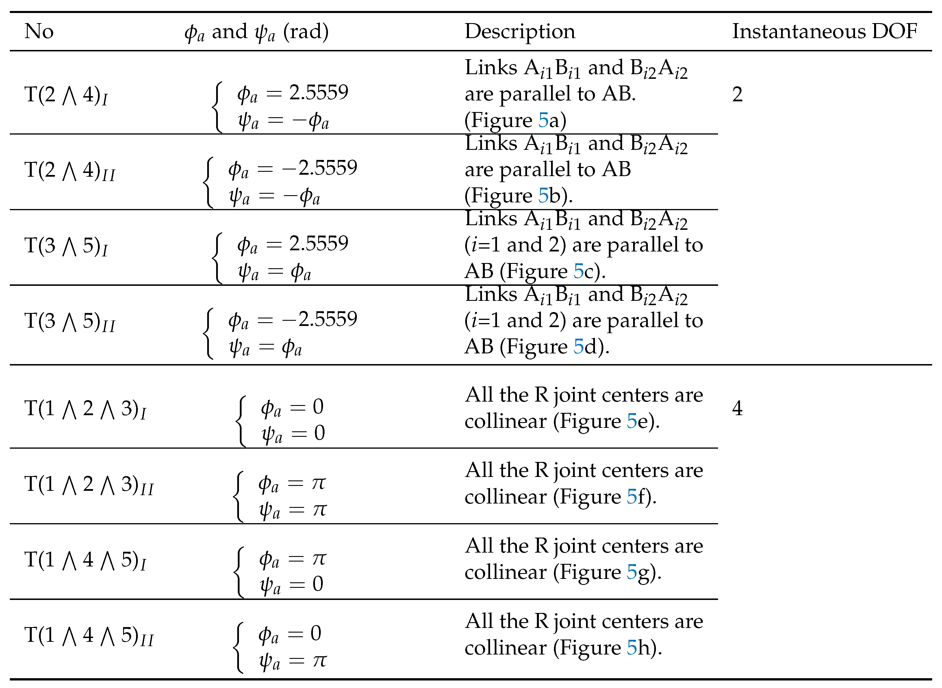
Equations (15) and (16) show that there are two transition configurations between motion modes 2 and 4, T(2 ⋀ 4) (Figure 5a) and T(2 ⋀ 4) (Figure 5b). In these two transition configurations, links AB and BA are parallel to AB. One can readily obtain that the instantaneous DOF of the 8-link variable-DOF mechanism is 2 in these transition configurations. The details are omitted here since the calculation of instantaneous DOF of a mechanism has been well-documented in the literature.
Following the above steps, we can identify six more transition configurations of the 8-link mechanism, including two transition configurations, T(3 ⋀ 5) (Figure 5c) and T(3 ⋀ 5)) (Figure 5d), in which the mechanism can switch between two motion modes and four transition configurations, (T(1 ⋀ 2 ⋀ 3) (Figure 5e), T(1 ⋀ 2 ⋀ 3) (Figure 5f), T(1 ⋀ 4 ⋀ 5) (Figure 5g), and T(1 ⋀ 4 ⋀ 5)) (Figure 5h), in which the mechanism can switch among three motion modes. It is noted that there are no transition configurations between motion modes 2 and 5 or between motion modes 3 and 4. The geometric characteristics of the 8-link mechanism in all the eight transition configurations are summarized in Table 2. All the transition configurations are singular configurations. The instantaneous DOF of the 8-link variable-DOF in transition configurations can be readily obtained as: 2 in transition configurations T(2 ⋀ 4), T(2 ⋀ 4), T(3 ⋀ 5) and T(3 ⋀ 5) and 4 in transition configurations T(1 ⋀ 2 ⋀ 3), T(1 ⋀ 2 ⋀ 3), T(1 ⋀ 4 ⋀ 5), and T(1 ⋀ 4 ⋀ 5).
5. Reconfiguration of the variable-DOF 8-link planar mechanism
Figure 6 illustrates the reconfiguration of the 8-link planar mechanism among the five motion modes via the eight transition configurations on the plane. The curves on the plane of the four 1-DOF motion modes, motion modes 2, 3, 4 and 5, are shown in green, pink, red and blue respectively. The 2-DOF motion mode, motion mode 1 in which , covers the whole plane. However, the 8-link mechanism can only transit among motion modes 1, 2 and 3 at two transition configurations T(1 ⋀ 2 ⋀ 3) and T(1 ⋀ 2 ⋀ 3) and among motion modes 1, 4 and 5 at two transition configurations T(1 ⋀ 4 ⋀ 5) and T(1 ⋀ 4 ⋀ 5) since we have in the other configurations in motion modes 2, 3, 4 and 5.
Photos of the LEGO model of this 8-link mechanism at all the transition configurations, configurations with and/or in 1-DOF motion modes 2, 3, 4 and 5, and a configuration with and in 2-DOF motion mode 1 are given. To distinguish the only 2-DOF motion mode from the 1-DOF motion modes, the photos of the sample configuration and the four transition configurations associated with motion mode 1 are framed. In the LEGO model, the links are allocated in six layers, and the axis of R joint A is in a curved shape to allow the mechanism to switch among all the five motion modes through the eight transition configurations without link interference. An animation of the reconfiguration of the 8-link mechanism among the five motion modes can be found in the supplementary materials. For simplicity reasons, all “⋀” are omitted in the notations for transition configurations in the animation.
The mechanism could be more compact if it is only required to switch among some but not all of its motion modes. For example, if one needs the 8-link mechanism to switch among four motion modes 1, 2, 4 and 5 only (Figure 7), all the links can be located in four layers without encountering link interference as shown in the CAD model of the mechanism in transition configuration T(1 ⋀ 4 ⋀ 5). This 8-link planar mechanism could be used as a construction unit of new variable-DOF multi-loop mechanisms, which would enrich the types of reconfigurable/multi-mode deployable mechanisms [24,25,26,36,44,45].
6. Conclusions
A novel 8-link variable-DOF planar mechanism with five motion modes has been proposed. Reconfiguration analysis has shown that the mechanism has one 2-DOF double parallelogram motion mode and four 1-DOF motion modes. In addition, the mechanism can switch among three motion modes at four transition configurations and between two motion modes at four other transition configurations.
In contrast to the two 8-link variable-DOF planar mechanisms in [5,41], which have four inactive joints in some of their motion modes, this novel 8-link variable-DOF planar mechanism has two inactive joints in one of its 1-DOF motion modes. The two 4R kinematic sub-chains of the novel mechanism must appear either as a pair of parallelograms in the 2-DOF motion mode or a pair of anti-parallelograms in a 1-DOF motion mode.
Both 4R kinematic sub-chains of this novel mechanism must appear as parallelograms in a pair or anti-parallelograms in a pair in the same motion mode.
The elimination and algebraic-geometry approach has been found to be more efficient than the algebraic geometry approach without elimination. As a by-product, a method for factoring trigonometric functions in two angles has been proposed.
This work, together with reference [41], provides a starting point for the design and analysis of variable-DOF multi-loop mechanisms constructed using more than two parallelograms, which could be used as reconfigurable/multi-mode deployable mechanisms.
Supplementary Materials
The following supporting information can be downloaded at the website of this paper posted on Preprints.org, Video S1: Reconfiguration of a novel 8-link variable-DOF planar mechanism with five motion modes.
Author Contributions
Conceptualization, X.K. and J.W.; methodology, X.K.; validation, J.W. and X.K.; formal analysis, X.K.; writing—original draft preparation, X.K. and J.W; writing—review and editing, X.K.; visualization, J.W. and X.K; All authors have read and agreed to the published version of the manuscript.
Funding
This research was funded by the Engineering and Physical Sciences Research Council (EPSRC) grant number EP/T024844/1, United Kingdom.
Data Availability Statement
The data presented in this study are available within the paper.
Acknowledgments
The authors would like to thank Miss Mary Kong from the University of Edinburgh for building the LEGO model of the 8-link variable-DOF mechanism shown in Figure 6.
Conflicts of Interest
The authors declare no conflict of interest.
Appendix A. Derivation of Eq. (2)
Solving the set of equations composed of the first and second equations in Eq. (1) as a set of linear equations in and , we have
To eliminate from Eq. (A1), rewrite the first equation in Eq. (A1) as
Squaring both sides, we have
Eliminating and from the above equation using the trigonometric identities and , we have
Solving the second equation in Eq. (A1) for , we obtain
Substituting Eq. (A3) into Eq. (A2), we obtain the following equation in L and .
Similarly, the third and fourth equations in Eq. (1) can be reduced to
Combining Eqs. (A4) and (A5), we obtain Eq. (2).
Appendix B. Derivation of Eq. (11)
Equation. (11) can be derived from Eq. (8) using the primary decomposition of ideals in the following five steps.
- Step 1:
-
Convert Eq. (8) into a polynomial equation.Substituting and into Eq. (8), we obtain a polynomial equation in and .where .
- Step 2:
-
Calculate the primary decomposition of ideal , where and . The last two polynomials correspond to the trigonometric identities and .Calculating the primary decomposition of using computer algebra system software, such as MAPLE command PrimeDecomposition(J, ’removeredundant’), we havewhere the irreducible components, and , of are:, and.
- Step 3:
-
Calculate the Gröbner basis for each irreducible component.Using the MAPLE command, Basis(J, tdeg(sa, ca, sb, cb)) , we obtain the Gröbner basis of as.Similarly, the Gröbner basis of is.
- Step 4:
-
Convert the polynomials in each of the irreducible components into trigonometrical functions.Substituting , , and into and simplifying the results, we obtain. i.e.,where .Similarly, we obtainwhere .
- Step 5:
-
Divide the trigonometrical function in Eq. (8) by the product of the trigonometrical functions obtained in Step 4.Divide g by , We can readily obtaini.e.
References
- F. Xi, J.S. Dai, X. Ding and V. Van der Wijk, Proceedings of the 5-th IEEE/IFToMM International Conference on Reconfigurable Mechanisms and Robots. Ryerson University, Toronto, Canada, 2021.
- J. Herder and V. van der Wijk, Proceedings of the 2018 International Conference on Reconfigurable Mechanisms and Robots (ReMAR 2018). Piscataway, NJ, USA: IEEE, 436 p., 2018.
- K. Wohlhart, Kinematotropic linkages, in: J. Lenarcic and V. Parenti-Castelli (Eds.), Recent Advances in Robot Kinematics, Kluwer Academic, Dordrecht, The Netherlands, 1996, pp. 359–368.
- M.D. Kovalev, Geometric theory of hinge mechanisms, Izvestiya RAN Seriya Matematicheskaya, 58(1) (1994) 45–70.
- C. Galletti, P. Fanghella, 2001, Single-loop kinematotropic mechanisms, Mechanism and Machine Theory, 36 (2001) 743–761. [CrossRef]
- X. Kong, M. Pfurner, Type synthesis and reconfiguration analysis of a class of variable-DOF single-loop mechanisms, Mechanism and Machine Theory, 85 (2015) 116–128. [CrossRef]
- P.C. López-Custodio, J.S. Dai, Design of a variable-mobility linkage using the Bohemian dome. ASME Journal of Mechanical Design 141(9) (2019), 092303. [CrossRef]
- H. Feng, Y. Chen, J.S. Dai, G. Gogu, Kinematic study of the general plane-symmetric Bricard linkage and its bifurcation variations, Mechanism and Machine Theory, 116(2017) 89–104. [CrossRef]
- P.C. Lopez-Custodio, J.M. Rico, J.J. Cervantes-Sánchez, G.I. Perez-Soto, Reconfigurable mechanisms from the intersection of surfaces, Journal of Mechanisms and Robotics, 8(2)(2016), 021029.
- P. Fanghella, C. Galleti, E. Gianotti, Parallel robots that change their group of motion, in: Advances in Robot Kinematics, Springer, 2006, pp. 49–56. [CrossRef]
- K. Liu, J. Yu, X. Kong, Structure synthesis and reconfiguration analysis of variable-degree-of-freedom single-loop mechanisms with prismatic joints using dual quaternions, J. Mechanisms Robotics, 14(2) (2022) 021009. [CrossRef]
- X. Kong, Type synthesis of variable degree-of-freedom parallel manipulators with both planar and 3T1R operation modes, in: Proceedings of ASME 2012 International Design Engineering Technical Conferences & Computers and Information in Engineering Conference, DETC2012-70621, 12-15 August, 2012, Chicago, USA.
- M. Coste, K.M. Demdah, Extra modes of operation and self motions in manipulators designed for Schoenflies motion, Journal of Mechanisms and Robotics, 7(4) (2015) 041020. [CrossRef]
- Q. Zeng, K.F. Ehmann, J. Cao, Design of general kinematotropic mechanisms, Robotics and Computer-Integrated Manufacturing, 38 (2016) 67–81. [CrossRef]
- D. Gan, J.S. Dai, and Q. Liao, Mobility change in two types of metamorphic parallel mechanisms. ASME Journal of Mechanisms Robotics, 1(4) (2009) 041007. [CrossRef]
- K. Zhang and J.S. Dai, Screw-system-variation enabled reconfiguration of the Bennett plano-spherical hybrid linkage and its evolved parallel mechanism. ASME Journal of Mechanical Design, 137(6) (2015) 062303. [CrossRef]
- L. Nurahmi, S. Caro, P. Wenger, J. Schadlbauer, M. Husty, Reconfiguration analysis of a 4-RUU parallel manipulator, Mechanism and Machine Theory, 96 (2016) 269–289. [CrossRef]
- L. Nurahmi, P. Putrayudanto, G. Wei, Guowu and S. K. Agrawal, Geometric constraint-based reconfiguration and self-motions of a four-CRU parallel mechanism, Journal of Mechanisms and Robotics, 13(2) (2021) 433748391. [CrossRef]
- X. Kong, Classification of a 3-RER parallel manipulator based on the type and number of operation modes, ASME Journal of Mechanisms Robotics, 13(2) (2021) 021013. [CrossRef]
- P.C. López-Custodio, A. Müller, and J.S. Dai, A kinematotropic parallel mechanism reconfiguring between three motion branches of different mobility. In: Uhl, T. (eds) Advances in Mechanism and Machine Science. IFToMM WC 2019. Mechanisms and Machine Science, vol 73. Springer, Cham. (2019) pp. 2611–2620.
- Y. Qin, J.S. Dai, G. Gogu, Multi-furcation in a derivative queer-square mechanism, Mechanism and Machine Theory, 81 (2014) 36–53. [CrossRef]
- X. Kong, Variable degree-of-freedom spatial mechanisms composed of four circular translation joints, ASME Journal of Mechanisms Robotics. 13(3) (2021) 031007. [CrossRef]
- Arponen, T., Piipponen, S. and Tuomela, J., Kinematical analysis of Wunderlich mechanism. Mechanism and Machine Theory, 70: 16–31, 2013. [CrossRef]
- J. Wang, X. Kong, A novel method for constructing multimode deployable polyhedron mechanisms using symmetric spatial compositional units, ASME Journal of Mechanisms Robotics. 11(2) (2019) 020907. [CrossRef]
- C. Tian, D. Zhang, H. Tang, C. Wu, Structure synthesis of reconfigurable generalized parallel mechanisms with configurable platforms, Mechanism and Machine Theory. 160 (2021) 104281. [CrossRef]
- R. Liu, R. Li, Y.-A. Yao, X. Ding, A reconfigurable deployable spatial 8R-like mechanism consisting of four angulated elements connected by R joints, Mechanism and Machine Theory. 179 (2023) 105103. [CrossRef]
- Z. Li, D.F. Scharler, H.-P. Schröcker, Factorization results for left polynomials in some associative real algebras: State of the art, applications, and open questions, Journal of Computational and Applied Mathematics. 349 (2019) 508–522. [CrossRef]
- A Montes, M. Wibmer, Software for discussing parametric polynomial systems: The Gröbner Cover, International Congress on Mathematical Software. (2014) 406–413.
- D.A. Cox, J.B. Little, D. O’Shea, Ideals, Varieties, and Algorithms, Springer, 2007.
- M.L. Husty, H.-P. Schröcker, Kinematics and algebraic geometry, in: J.M. McCarthy (Ed.), 21st Century Kinematics, Springer, 2013, pp. 85–123.
- C. Wampler, A. Sommese, Numerical algebraic geometry and algebraic kinematics. Acta Numerica, 20 (2011) 469–567. [CrossRef]
- A. Shabani, J. M. Porta, F. Thomas, A branch-and-prune method to solve closure equations in dual quaternions, Mechanism and Machine Theory, 164 (2021) 104424. [CrossRef]
- S. Pellegrino, Structural computations with the singular value decomposition of the equilibrium matrix, International Journal of Solids and Structures, 30(21) (1993) 3025–3035. [CrossRef]
- C.Y. Song, Y. Chen, I-M. Chen, A 6R linkage reconfigurable between the line-symmetric Bricard linkage and the Bennett linkage, Mechanism and Machine Theory. 70 (2013) 278–292. [CrossRef]
- Y. Wang, Q. Zhang, X. Zhang, J. Cai, C. Jiang, Y. Xu, J. Feng, Analytical and numerical analysis of mobility and kinematic bifurcation of planar linkages, International Journal of Non-Linear Mechanics, 145 (2022) 104110. [CrossRef]
- X. Kang, H. Lei, B. Li, Multiple bifurcated reconfiguration of double-loop metamorphic mechanisms with prismatic joints, Mechanism and Machine Theory, 178 (2022) 105081. [CrossRef]
- A. Müller, Local kinematic analysis of closed-loop linkages - Mobility, singularities, and shakiness, Journal of Mechanisms and Robotics. 8 (2016) 041013-1.
- P.C. Lopez-Custodio, J.M. Rico, J.J. Cervantes-Sanchez, G.I. Perez-Soto, C.R. Díez-Martínez, 2017. Verification of the higher order kinematic analyses equations, European Journal of Mechanics A/Solids. 61 (2017) 198–215.
- P.C. Lopez-Custodio, J.M. Rico, J.J. Cervantes-Sanchez, Local analysis of helicoid-helicoid intersections in reconfigurable linkages, Journal of Mechanisms and Robotics. 9(3) (2017) 031008-031008-17.
- A. Müller, Recursive higher-order constraints for linkages with lower kinematic pairs, Mechanism and Machine Theory, 100 (2016) 33–43. [CrossRef]
- X. Kong, A novel construction method for the type synthesis of variable-DOF mechanisms, in: F. Xi, J.S. Dai, X. Ding and V. van der Wijk (Eds.), Proceedings of the 5th IEEE/IFToMM International Conference on Reconfigurable Mechanisms and Robots. Ryerson University, Toronto, Canada, 2021. pp. 31–40.
- X. Kong, Motion/structure mode analysis and classification of n-RR planar parallelogram mechanisms, Mechanism and Machine Theory. 169 (2022) 104623.
- S. Qiao, Q. Liao, S. Wei, H.-J. Su, Inverse kinematic analysis of the general 6R serial manipulators based on double quaternions, Mechanism and Machine Theory. 45(2) (2010) 193–199. [CrossRef]
- G. Kiper, F. Gürcü, K. Korkmaz, E. Söylemez, Kinematic design of a reconfigurable deployable canopy. In: P. Flores, F. Viadero (Eds.) New Trends in Mechanism and Machine Science. Mechanisms and Machine Science, vol 24. Springer, Cham, 2015.
- Y. Gao, F. Yang, J. Zhang, A reconfigurable 6R linkage with six motion modes and three topological structures, ASME Journal of Mechanisms Robotics. 15(5) (2023) 054503. [CrossRef]
| 1 | Variable-DOF mechanisms in this paper are composed of conventional kinematic joints and have no reconfigurable joints. For variable-DOF mechanisms with reconfigurable joints, please refer to reference [15]. |
| 2 | Two solutions, (rad), to Eq. (14) that lead to were discarded. |
Figure 1.
A novel 8-link variable-DOF planar mechanism.
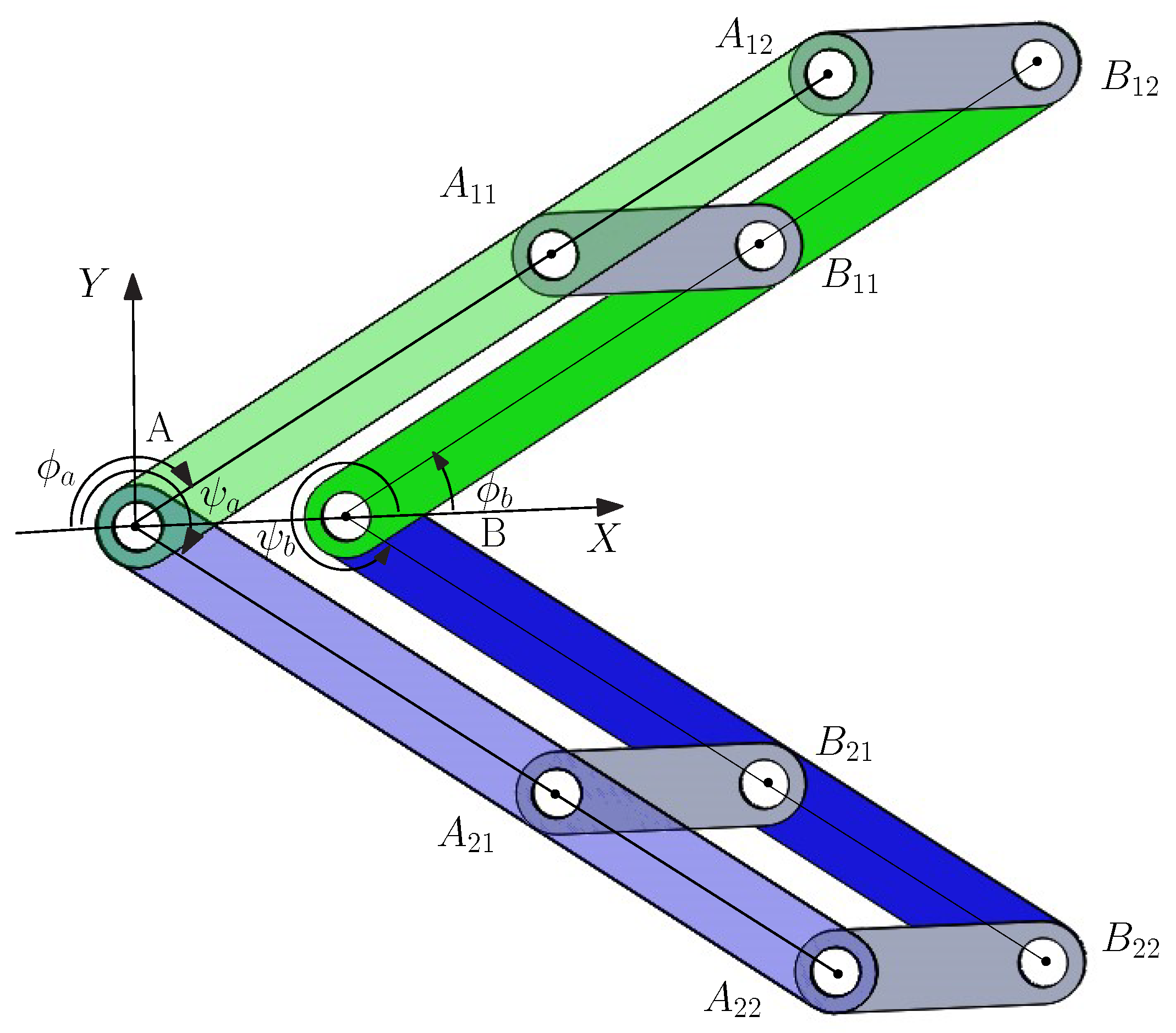
Figure 2.
The 8-link variable-DOF planar mechanism in: (a) 2-DOF Motion mode 1; (b) 1-DOF Motion mode 2; (c) 1-DOF Motion mode 3; (d) 1-DOF Motion mode 4; and (e) 1-DOF Motion mode 5.
Figure 2.
The 8-link variable-DOF planar mechanism in: (a) 2-DOF Motion mode 1; (b) 1-DOF Motion mode 2; (c) 1-DOF Motion mode 3; (d) 1-DOF Motion mode 4; and (e) 1-DOF Motion mode 5.
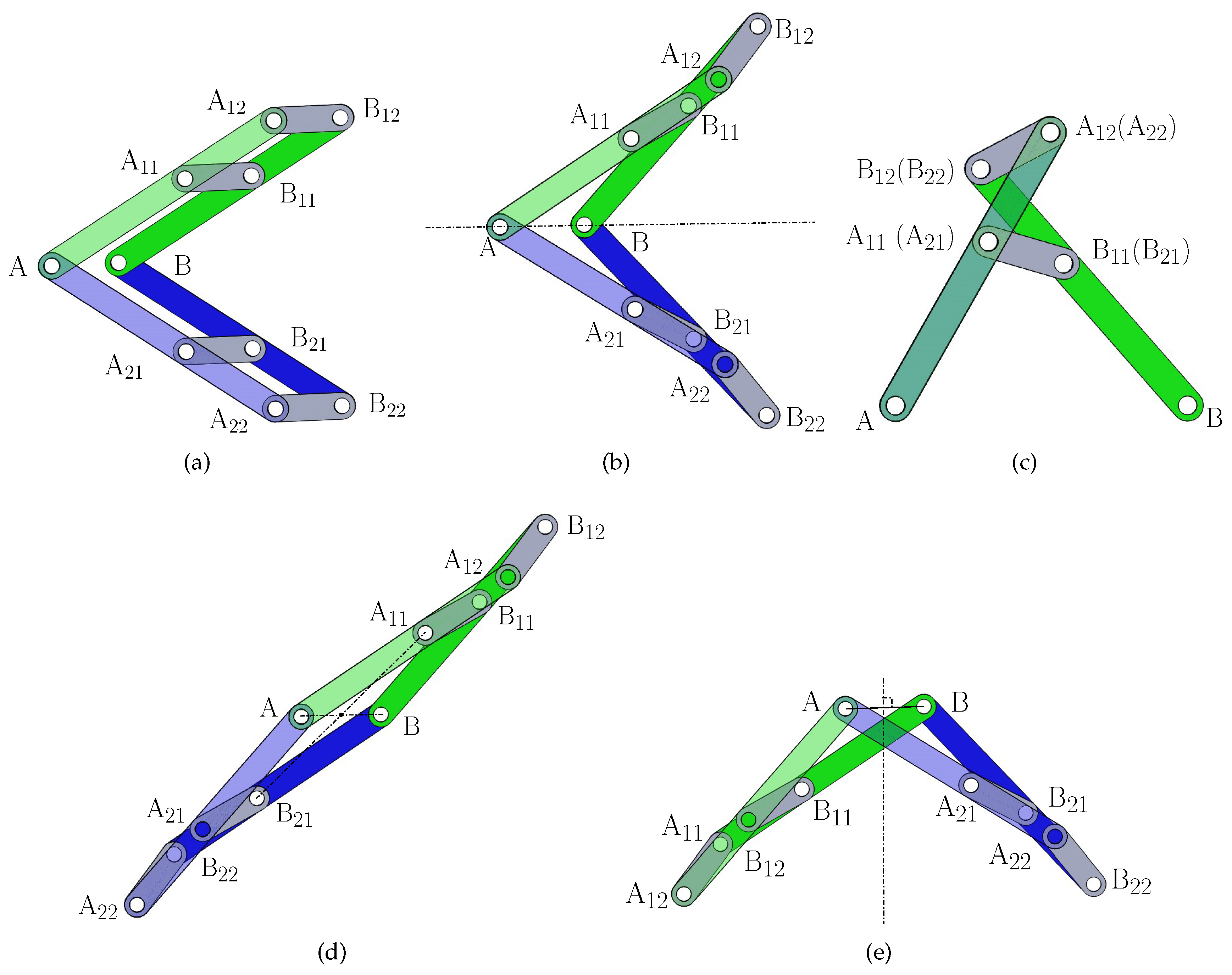
Figure 3.
Kinematic analysis of the 8-link variable-DOF planar mechanism in: (a) motion mode 4; (b) motion mode 5.
Figure 3.
Kinematic analysis of the 8-link variable-DOF planar mechanism in: (a) motion mode 4; (b) motion mode 5.
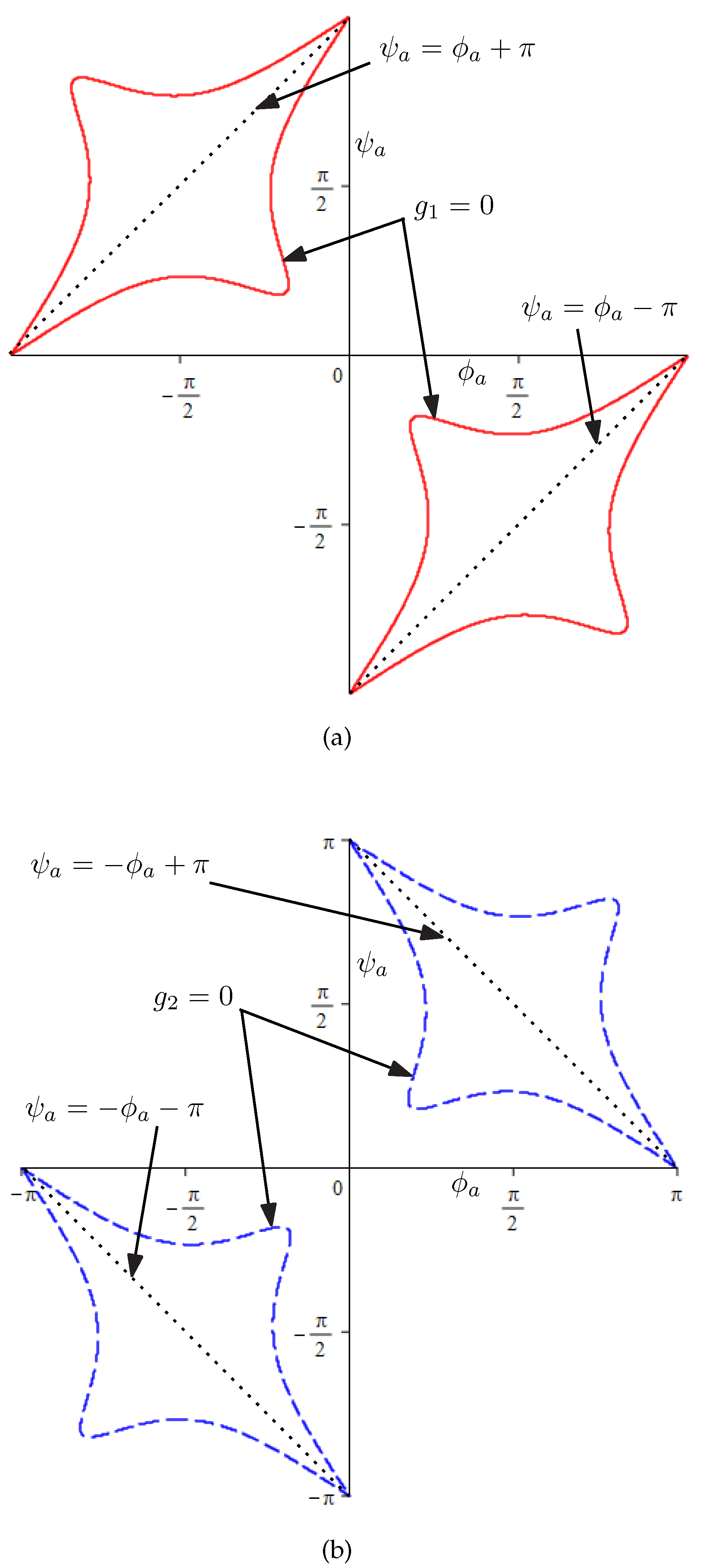
Figure 4.
Four 1-DOF motion modes on - plane.
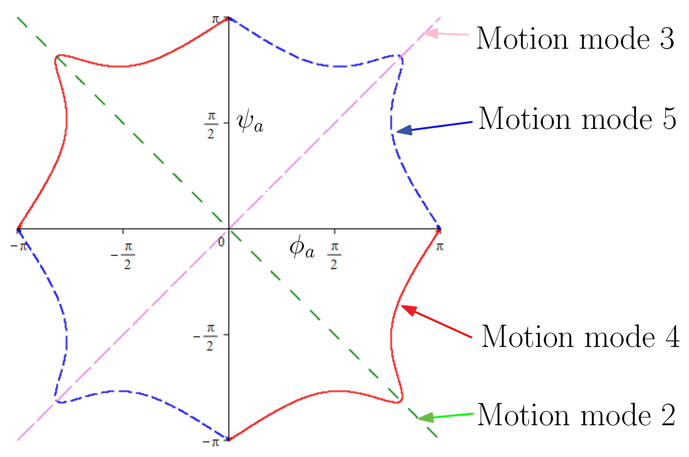
Figure 5.
The 8-link variable-DOF planar mechanism in transition configuration: (a) T(2 ⋀ 4); (b) T(2 ⋀ 4); (c) T(3 ⋀ 5); (d) T(3 ⋀ 5); (e) T(1 ⋀ 2 ⋀ 3); (f) T(1 ⋀ 2 ⋀ 3); (g) T(1 ⋀ 4 ⋀ 5); and (h) T(1 ⋀ 4 ⋀ 5).
Figure 5.
The 8-link variable-DOF planar mechanism in transition configuration: (a) T(2 ⋀ 4); (b) T(2 ⋀ 4); (c) T(3 ⋀ 5); (d) T(3 ⋀ 5); (e) T(1 ⋀ 2 ⋀ 3); (f) T(1 ⋀ 2 ⋀ 3); (g) T(1 ⋀ 4 ⋀ 5); and (h) T(1 ⋀ 4 ⋀ 5).
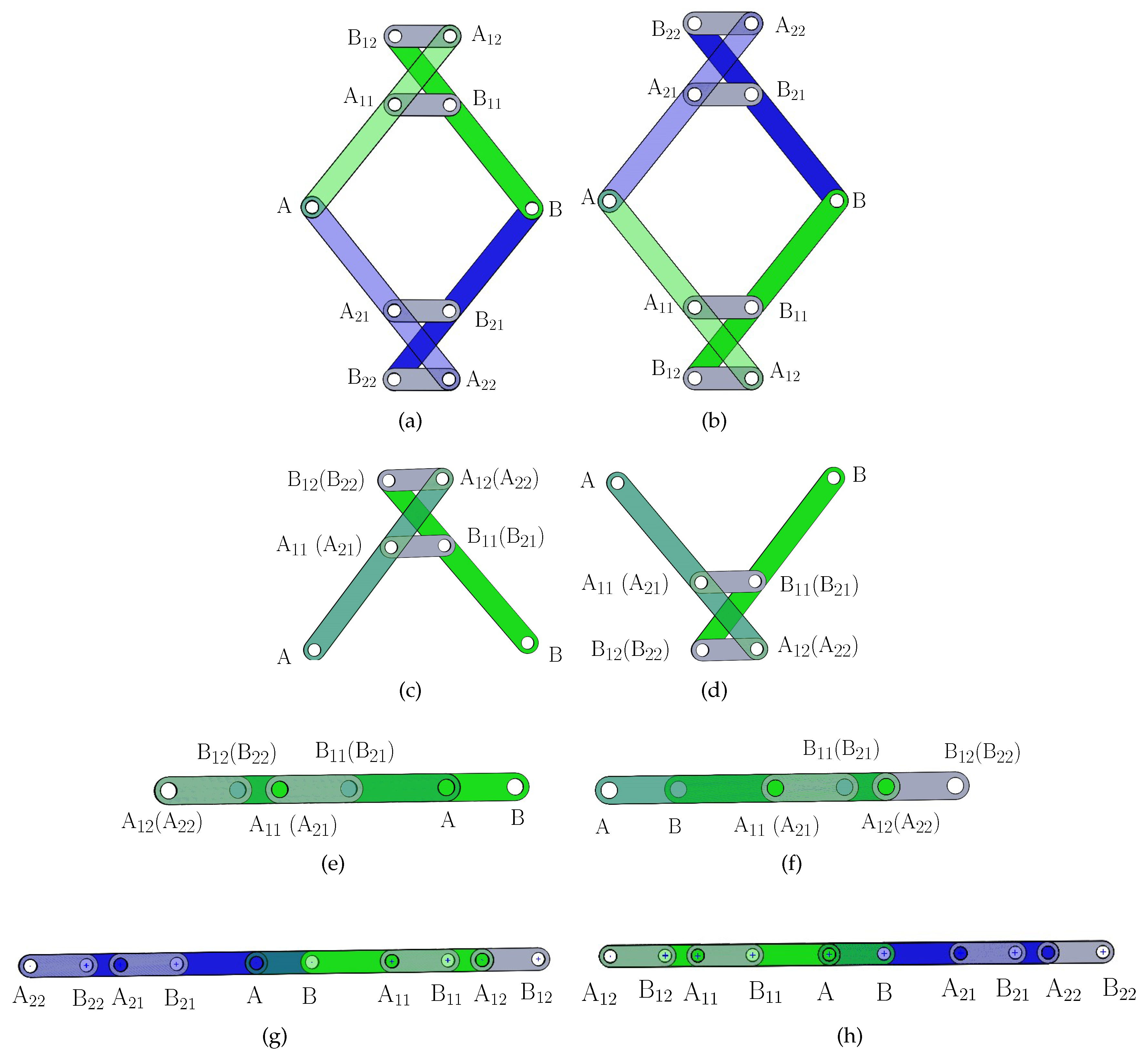
Figure 6.
Reconfiguration of the example variable-DOF 8-link planar mechanism among the five motion modes.
Figure 6.
Reconfiguration of the example variable-DOF 8-link planar mechanism among the five motion modes.
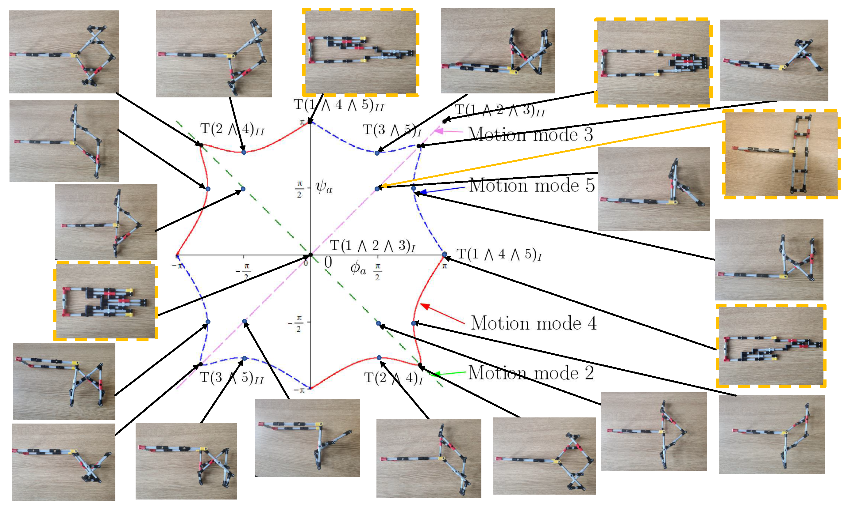
Figure 7.
A variable-DOF 8-link planar mechanism in compact design that can transit among four motion modes.
Figure 7.
A variable-DOF 8-link planar mechanism in compact design that can transit among four motion modes.
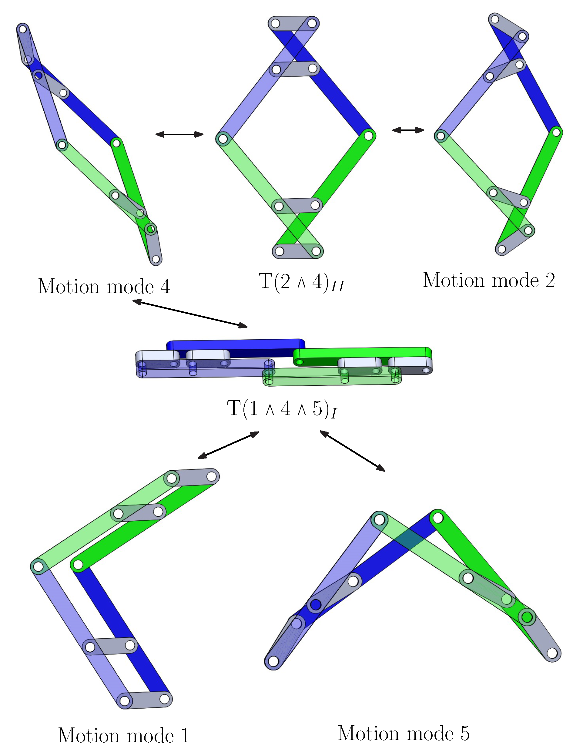

Table 1.
Five motion modes of the 8-link variable-DOF mechanism.
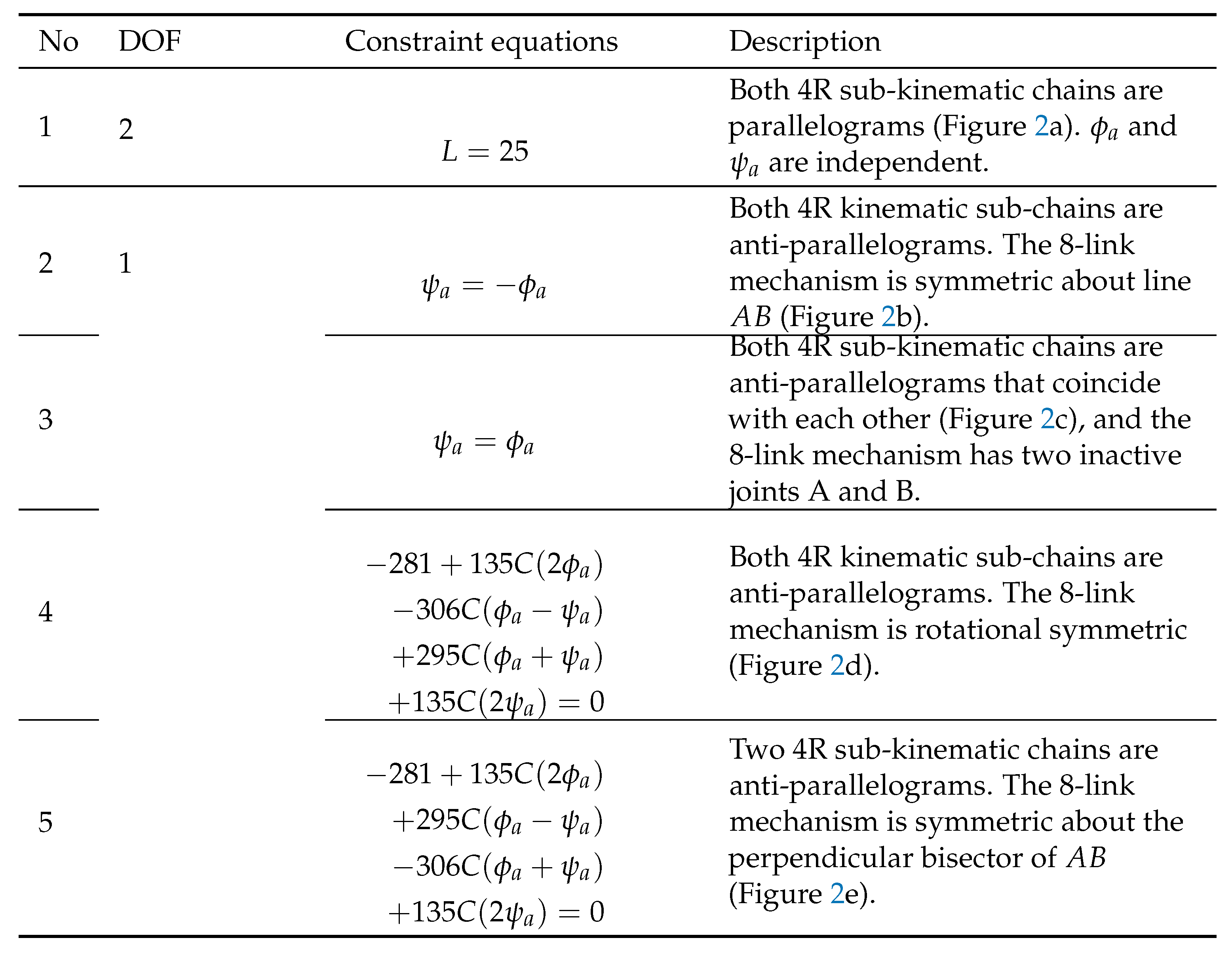
Table 2.
Transition configurations of the 8-link mechanism.
Disclaimer/Publisher’s Note: The statements, opinions and data contained in all publications are solely those of the individual author(s) and contributor(s) and not of MDPI and/or the editor(s). MDPI and/or the editor(s) disclaim responsibility for any injury to people or property resulting from any ideas, methods, instructions or products referred to in the content. |
© 2023 by the authors. Licensee MDPI, Basel, Switzerland. This article is an open access article distributed under the terms and conditions of the Creative Commons Attribution (CC BY) license (http://creativecommons.org/licenses/by/4.0/).
Copyright: This open access article is published under a Creative Commons CC BY 4.0 license, which permit the free download, distribution, and reuse, provided that the author and preprint are cited in any reuse.


