
Submitted:
20 January 2023
Posted:
23 January 2023
You are already at the latest version
Abstract
Synchronous homopolar machines (SHM) with excitation winding on the stator have attracted the attention of researchers for many decades due to their high reliability. They are used in a variety of applications such as aircraft and railway generators and traction motors. At the same time, the three-dimensional structure of their magnetic circuit makes the problem of their analysis and optimization challenging. This problem becomes even more complicated when considering an SHM with hybrid excitation, with ferrite magnets in the rotor slots. The article proposes a mathematical procedure for optimizing a synchronous homopolar generator with hybrid excitation based on the single-criterion Nelder-Mead method and two-dimensional finite element analysis (FEA). The use of the Nelder-Mead method compared to multicriteria methods and 2D FEA compared to 3D FEA makes possible to significantly reduce the computational burden. As a result of optimization, the power loss and torque ripples of the generator are significantly reduced. The article also compares the characteristics of synchronous homopolar generators with and without ferrite magnets.
Keywords:
electrically excited synchronous machine
; Nelder–Mead method
; optimal design of electric machines
; synchronous homopolar generator
; synchronous homopolar machine
; undercar generator
MSC: 00A06
1. Introduction
Generators with rare-earth permanent magnets are widely used when operating with a controlled rectifier [1]. At the same time, many researchers are looking for alternatives without rare earth magnets, since rare earth magnets are expensive, and their use makes the manufacturer dependent on a limited number of suppliers. The price of rare earth magnets can show strong fluctuations and changes several times, depending on the situation on the world market. Mining of rare earth elements harms the environment [2].
In addition, electric machines with rare earth magnets have disadvantages in operation. Nd-Fe-B rare earth magnets are not well suited for high temperature applications due to their tendency to permanently demagnetize at temperatures above 120°C and strong demagnetizing fields. While more temperature resistant Sm-Co magnets are available, due to the high cost and difficulty in machining, they are typically only used in aerospace systems [3].
The electrical conductivity of rare earth magnets is relatively high, therefore, at a high operating frequency, large eddy currents are induced in rare earth magnets, which leads to their high heating and complicates their use in high-speed applications. Magnetomotive force (MMF) from permanent magnets is uncontrollable and cannot be turned off in emergency situations, which complicates the use of the machines with rare earth magnets in many applications [4]. An alternative is wound rotor electrically excited synchronous generators (WRSG). However, their conventional designs cannot be used in many applications due to the presence of slip rings and brushes feeding the excitation winding on the rotor, which are subject to rapid wear [5]. It is also a problem to ensure the cooling of the WRSG rotor, which has significant electrical losses.
WRSGs with a brushless exciter are used in a number of applications such as aircraft generators and high power generators [6,7]. The disadvantages of WRSGs with a brushless exciter, compared with brushed WRSGs, include an increase in the cost, dimensions, and weight of the machine due to the presence of a brushless exciter. Also in this case, there are problems of reliability and repair of the brushless exciter assembly.
Brushless synchronous homopolar machines (SHMs) with axial excitation flux and stator-fixed concentric coils of the excitation winding are known for their high reliability, due to which they find use in flywheel energy storage, traction motors, as well as welding, automotive and aircraft generators [8,9,10]. They can be used at high temperatures and in hazardous environments as drives [11] and as high-power wind generators [12]. The main benefit of SHMs, in comparison with conventional generators with electrical excitation of the rotor, is high reliability due to the simple rotor without windings and because there are no sliding contact and reliable concentric excitation winding coils located on the stator. At the same time, SHMs retain the ability to control the excitation current, as in a conventional electrically excited generator.
SHM has a complex configuration of the magnetic system, which is challenging for calculation and optimization, since the magnetic flux propagates in all three dimensions. In some parts of the machine, the flux flows in the axial direction, and in others do in the transverse plane (in the tangential and radial directions) and changes its direction to axial one when moving from the laminated parts to the solid stator housing or magnetic sleeve on the rotor shaft. The complex three-dimensional design of the magnetic circuit causes difficulties when using conventional two-dimensional models based on the finite element analysis (FEA) to evaluate the characteristics of SHM. For this reason, a number of original calculation methods have been proposed for SHM, including three-dimensional FEA models [13,14], two-dimensional FEA models [15,16], one-dimensional magnetic circuits, and their various combinations [17,18]. In [16], a simplified SHM modeling technique was proposed, in which the features of the magnetic field are taken into account within the framework of a two-dimensional model by introducing an additional term into the equations of the vector magnetic potential, and jointly solving them with the one-dimensional equation of the axial magnetic circuit of the excitation flux. An experimental verification of this technique is carried out.
In [8,14,15,19-21], the analysis of SHM characteristics for various generator applications is considered. In [20], the modeling and tuning of the control system of a high-speed synchronous homopolar generator (SHG) is considered. In [14], the analytical expressions for designing and the results of 3D FEA of a high-speed SHG with a power of 10 kW and a rotation speed of 24 krpm are described. In [17], the simulation of a low-power SHG with a speed of 3000 rpm at idle is considered using a 2D FEA with virtual excitation windings. In [8], a theoretical evaluation of the characteristics of a 500 kW SHG with a superconducting excitation winding is presented. In [21], manual optimization of SHG performance at no-load is considered and an experimental verification is carried out.
Despite the SHM advantages, the losses in SHM with the same dimensions are significantly higher than in conventional WRSG due to less efficient use of the rotor surface [5]. Further improvement of the characteristics of SHGs is possible by adding ferrite magnets in their design. Ferrite magnets are several times cheaper than rare-earth ones and the extraction of raw materials for their production, as well as their production, exist in many countries of the world. Ferrite magnets are also well suited for use in high-temperature applications and have very low electrical conductivity, which makes them suitable for high-speed applications [23].
An SHG with ferrite magnets is presented in [22,23] as an undercar generator for railway passenger cars. It is shown that the use of SHGs with ferrite magnets have the following main advantages compared to SHGs without magnets: 1) The reduction of the weight and dimensions of the machine; 2) Power loss reduction. In [22], the calculation of the electromotive force (EMF) of SHG with ferrite magnets at idle is carried out, however, the calculation of the performances under load and the analysis of irreversible demagnetization were not carried out. In [23], a design of SHG with ferrite magnets is described in more detail.
Therefore, the review of the literature shows that the performance optimization of SHG with ferrite magnets under load has never been presented.
The novelty of this article lies in the development of a technique for optimizing the on-load performance of SHG with ferrite magnets as a railway undercar generator. The cost function is constructed, and a relevant example of the optimized design is obtained. The optimization of the SHG with ferrites minimizes losses, semiconductor rectifier current, torque ripple, and the volume of irreversibly demagnetized permanent magnets. A comparison between the SHG with ferrite magnets and the SHG without magnets in the target application is also presented. The characteristics of the SHG without magnets for the comparison are adopted from our previous study [24].
2. General Description of the SHG Design
As Figure 1 shows, the SHG has two laminated steel stator-rotor stack combinations (SRSCs). In the axial direction, the excitation magnetic flux is transmitted through the non-laminated stator housing, in which the stator laminated stacks are installed, and through the rotor sleeve, on which the laminated rotor stacks are installed. The stator winding has 12 poles and 54 slots with the number of slots per pole and per phase q = 54/(12∙3) = 1.5. The excitation winding is located in an axial gap between the two generator SRSCs. The rotor is salient-pole and without any windings. Each rotor stack has 6 teeth. The rotor stacks of neighboring SRSCs have a relative tooth shift of 30 mechanical degrees.
Magnets are installed in the rotor slots between the rotor teeth. It is assumed that the generator produces power to the DC link through a controlled rectifier with transistor switches, as shown in the diagram in Figure 2. An excitation winding is located between the SRSCs and is attached to the supporting non-magnetic core. The rotor has no windings. Each rotor stack has six teeth, and the teeth of the rotor stacks are shifted by 30 mechanical degrees with respect to each other.
Figure 2 shows the rectifier circuit layout for the considered generator. The required DC voltage (close to the maximum amplitude of the line-to-line voltage of the electric machine) should not exceed 116 V.
Figure 1.
SHG approximate geometry: (a) Cross-section and stator armature winding configuration (1/4 of the generator cross-section is shown, the other parts are symmetrical); (b) General view. 1/2 stator cutout is shown. Rotor is shown without cutout. The armature winding placed in the stator slots is not shown.
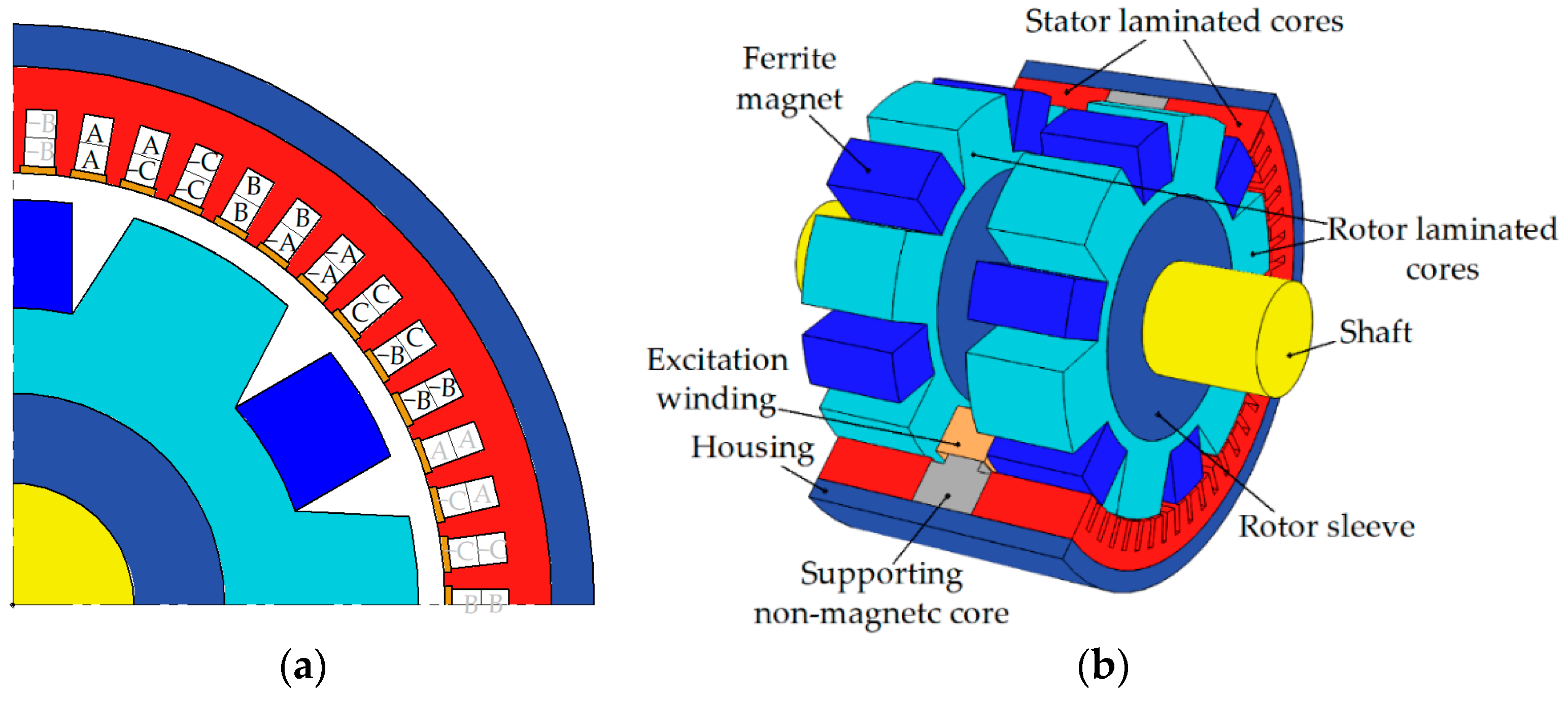
Figure 2.
Schematics of the three-phase controlled rectifier with a DC-chopper to supply the excitation winding.
Figure 2.
Schematics of the three-phase controlled rectifier with a DC-chopper to supply the excitation winding.

At the preliminary calculations, it was established that without parallel branches, each layer of the armature winding should contain 1 turn. This leads to large eddy losses. Therefore, the number of parallel branches is chosen equal to the number of pairs of poles i.e. 6.
3. SHG Mathematical Model
An SHG without ferrite magnets consists of two or more SRCSs connected to each other in the axial direction by ferromagnetic structural elements. The excitation current is provided by the excitation winding located on the stator. The magnetic flux of the excitation winding is closed through the SRCSs by means of the stator housing and the sleeve on the rotor shaft [21,25]. This magnetic flux is modulated by the rotor teeth, which allows it to interact with the poles of the stator winding. In this case, half of the poles are involved. The addition of ferrite magnets to the SHG makes it possible to use all poles of the stator winding.
The developed mathematical model consists of a set of g boundary 2D magnetostatic problems for a magnetic field in the cross section of an SRCS and a magnetic circuit equation with lumped parameters in the axial direction. The range of considered rotor position angles is chosen taking into account the symmetry with respect to a shift by a third of the electric period and cyclic phase permutation and is equal to a third of the electric period. One third of the electric period is divided into g sections and boundary value problems are considered for the beginning of each section. In this study, g = 24.
As in conventional electric machines, the magnetic field in a good approximation can be assumed to be uniform along the axis and lying in the transverse plane. Therefore, the equations traditional for 2D problems of magnetostatics are solved [16]:
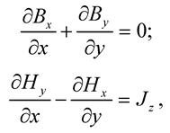 where Jz is the z-component of the current density, which is not equal to zero only in the stator slots filled with a winding; Bx and By are the components of the magnetic flux density; Hx and Hy are the components of the magnetic field.
A distinctive feature of SHM is the presence of a magnetic monopole, i.e. excitation flux flowing in on the inner boundary of the rotor and flowing out of the outer boundary of the stator (or vice versa). Then the general solution of the Gauss law for magnetism (1) can be expressed as follows:
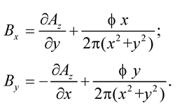 where Az is the z-component of the vector potential, ϕ is the linear density of the magnetic charge. The first components on the right side of these equations are common for a magnetostatic problem. The magnetic vector potential A is chosen so that only the Az-component is non-zero. The second term in these equations introduces the linear flux density of the magnetic monopole, which models the excitation flux. This flux passes through the rotor sleeve and stator housing, and through the SRCSs of length a/2, and is determined as follows:
Φ = ϕ∙a/2.
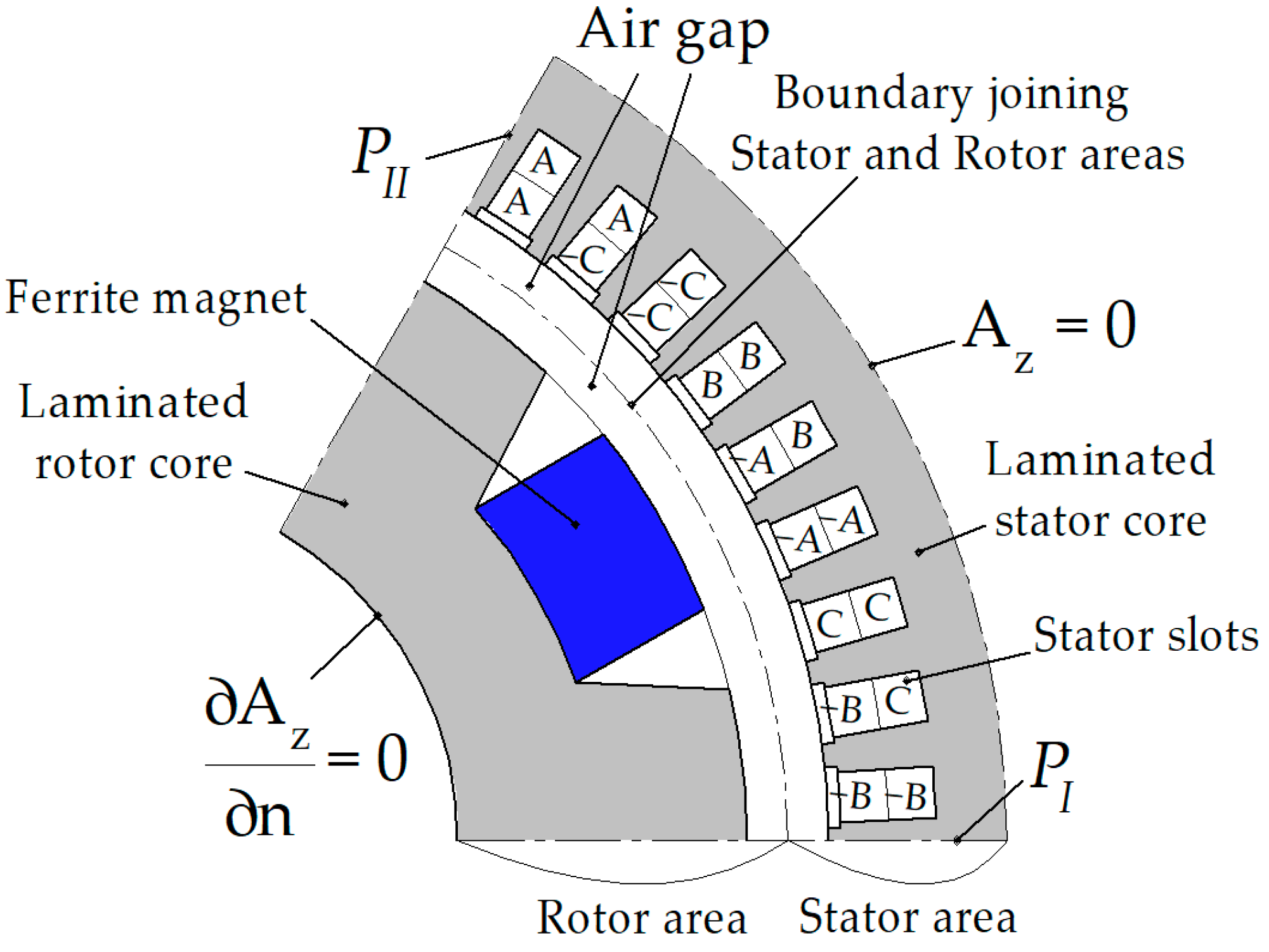
The same computational domain shown in Figure 3 Is used for magnetostatic problems with different rotor positions. The computational area is a sector equal to one electrical period (360°/p, where p is the number of poles). The computational domain is divided into two subdomains by an arc lying in the center of the air gap between the stator and rotor. The boundary condition connecting the magnetic vector potential on the common boundary of the subdomains ensures the continuity of the vector potential on both sides of the arc. The correspondence of points on both sides of the arc depends on the angular position of the rotor. Periodic boundary conditions (PI and PII) ensure the equality of the magnetic vector potential at the boundaries that limit the sector of the computational domain by one electrical period.
Figure 3.
Computational domain.
The equations of magnetostatics are complemented by constitutive equations. For the rotor and stator stacks, the magnetization curve H(B) is set. For magnets, the residual magnetic flux density and the magnetic permeability are set. For the areas of the armature winding, the current density is set, and the flux coupled to the winding is calculated, which is necessary to calculate the voltage in the armature winding.
The rotor rotates together with the rotating field, and there are practically no eddy currents in its stack and sleeve. Since the rotor sleeve is ferromagnetic, the normal derivative of Az is equal to zero at the inner boundary of the rotor package (the Neumann boundary condition).
On the contrary, the magnetic flux is frozen into the stator housing, and the normal component of the magnetic flux density at the outer boundary of the stator stack is represented only by the monopole field. Thus, for the outer boundary of the stator stack, the Dirichlet boundary condition Az = 0 is accepted.
Due to the fact that the field is frozen into the stator housing, we will assume that the magnetic charge does not change in time, and when calculating the MMF drop on a pair of rotor and stator stacks, we will use the average value for all boundary value problems. MMF can be calculated as a curvilinear integral of magnetic field along any trajectory from the inner boundary of the rotor stack to the outer boundary of the stator stack. Radial segments can be chosen as such trajectories. However, due to the discreteness of the finite element method, such integrals will have a small accuracy. Therefore, it is better to average over the azimuthal angle the values of these integrals. Therefore, the MMF drop on one pair of rotor and stator stacks is determined by the formula:
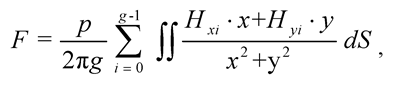 where the double integral ∫∫ is taken over the entire computational domain.
The magnetic circuit equation in the axial direction has the form [16]:
where Iexc is the excitation winding current; N is the number of turns of the excitation winding; F is the drop in MMF on one SRCS; Fhousing = λ ∙ Hhousing (Φ/Shousing) is the MMF drop on the stator housing; Fsleeve = λ ∙ Hsleeve (Φ/Ssleeve) is the MMF drop on the rotor sleeve; Hhousing and Hsleeve are the dependences of the magnetic field on the magnetic flux density in the stator housing and in the rotor sleeve, respectively; Shousing and Ssleeve are the cross-sectional areas of the housing and sleeve; λ is the axial distance between the SRCSs.
N ∙ Iexc = 2 ∙ F + Fhousing + Fsleeve,
The torque created by one SRCS and the EMF induced in the armature winding of one SRCS are called nonsymmetrized. The torque and EMF of the whole machine are equal to the sum of the torque and the EMF of each SRCS. To find the torque and EMF of the whole machine, there is no need to calculate them for each SRCS. It is assumed that the torque of the second SRCS is equal to that of the first SRCS, and the EMF is equal to that of the first SRCS with a sign ‘−‘ when the rotor is shifted by half the electric period [16]. Further the torque ripple of the whole machine is referred to as symmetrized torque ripple. The torque ripple as a single SRVS is referred to as nonsymmetrized torque ripple. The iron losses in the stator and rotor cores are evaluated in postprocessing based on the flux density waveforms in each finite element obtained after solving g boundary value problems.
4. Operating Points of the Undercar Generator, Variable Geometric Parameters, Objective Function
Like traction motors, an undercar generator is an electrical machine, operating over a wide range of speeds at a constant required output power. However, in the case of a generator, a constant electrical output is required. The rotational speed of an undercar generator increases together with the velocity of the train. The operating speed range of the considered undercar generator is from 750 to 3450 rpm. The generator must produce about 35 kW in this speed range [26]. In order to simplify the optimization procedure, it was assumed that the mechanical power of the generator does not change and is equal to Pmax = 40 kW > 35 kW in the entire considered speed range, roughly taking into account the generator loss. Two boundary points are considered in the optimization: the speed n1 = 3450 rpm at the torque of Tmax ∙ n2/n1 = 111 N∙m and the speed n2 = 750 rpm at the torque of Tmax = 510 N∙m (Figure 4).
Figure 4.
The dependence of the mechanical power on the generator shaft on the rotational speed.

During the optimization, it is necessary to minimize the following characteristics of the generator (the most important characteristics are listed first):
- Minimization of average losses < Ploss > which is estimates as the average losses in the modes with the speeds of 750 rpm and 3450 rpm;
- Minimization of the maximum value of the stator current (reached at 750 rpm mode);
- Minimization of the maximum symmetrized torque ripple max(Trsym) in both modes;
- Minimization of the maximum nonsymmetrized torque max(TR) in both modes;
- Minimization of the volume of irreversibly demagnetized magnets at maximum current at a speed of 750 rpm.
When optimizing, both the torque ripple TR of a separate SRSC and the torque ripple Trsym resulting from the addition of the torque waveforms of all SRSCs of the SHG are considered [16].
The material for the housing and the sleeve is solid steel 1010. Since the magnetic properties of structural steel (a non-laminated steel used for making construction materials) are not reported and are not guaranteed by the manufacturer, in order to guarantee that the drop of the magnetomotive force on the axial magnetic cores will be small compared to the drop on the SRSC, in the course of optimization, the flux density in the stator housing and in the rotor sleeve is limited to 1.6 T.
In this study, the single-criterion unconditional Nelder-Mead method is used to optimize the SHG design, which is well known [27] and is included in the basic MATLAB software package (“fminsearch” function). Therefore, the objective function is given as a product of individual characteristics raised to a certain power, reflecting the importance of the characteristic. Optimization constraints cannot be set by assigning an infinite value to the optimization function if these conditions are not met, as this would lead to a rapid decrease in the volume of the simplex, and convergence to an undesirable local minimum. Therefore, the maximum flux density constraint and the maximum demagnetization area are set as a soft constraint, that is, the corresponding multipliers increase rapidly if their constraints are not complied. In view of the above, the objective function is defined as follows:
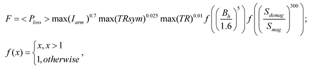 where < Ploss > are the average losses (arithmetic mean of losses at operating points at 750 and 3450 rpm); max(Iarm) is the maximum armature current that occurs at the 2nd operating point (the maximum torque; 750 rpm); max(Trsym) is the maximum value of the symmetrized torque ripple; max(TR) is the maximum value of the nonsymmetrized torque ripple; Bh is magnetic flux density in the stator housing and rotor sleeve at the 2nd operating point; Sdemag is the area of the demagnetized magnets; Smag is the total area of the magnets.
The constants 1, 0.7, 0.025 and 0.01 in (6) determine the importance of certain objectives. The most important optimization objective is to reduce the average loss, so the corresponding < Ploss > multiplier raised to the highest power. The constant 0.7 means that a 1% reduction in the current at 750 rpm is considered as valuable as a 0.7% reduction in the average loss. The objectives of reducing symmetrized and unsymmetrized torque ripples are substantially less important. The constants 0.025 and 0.01 mean that other things being equal, designs with lower torque ripples are preferable.
The last two multipliers of function (6) set the soft constraints of flux density in non-laminated parts of the magnetic circuit and the area of irreversibly demagnetized ferrite magnets. The constants 5 and 300 control the steepness of the constraints. Too small values of these constants can lead to constraint violations, i.e. to an unacceptable design. Calculations show that the optimized design satisfies the constraints (flux density in the housing and in the sleeve is no more than 1.6 T, demagnetizing force is 3.9 kOe). Too large values cause fast reduction of the volume of the simplex, which slows down optimization.
To simplify the optimization algorithm, optimization is carried out under the assumption that the number of turns in the armature winding layer Nsec is a real number and may take non-integer values. Also, the height and width of the winding wire can be arbitrary real numbers, without taking into account the limitations of the standard assortment [28]. The number of turns is selected so as to the amplitude value of the line voltage V3450 in the 40 kW, 3450 rpm (maximum voltage) operating point is equal to 113 V [5]. Number of parallel branches is assumed to be equal to 6. Figure 5 Shows the geometric parameters of the SHG.
Figure 5.
Parameters of the SHG geometry. (a) Stator slot; (b) Rotor core; (c) Stator winding; (d) Other dimensions.
Figure 5.
Parameters of the SHG geometry. (a) Stator slot; (b) Rotor core; (c) Stator winding; (d) Other dimensions.
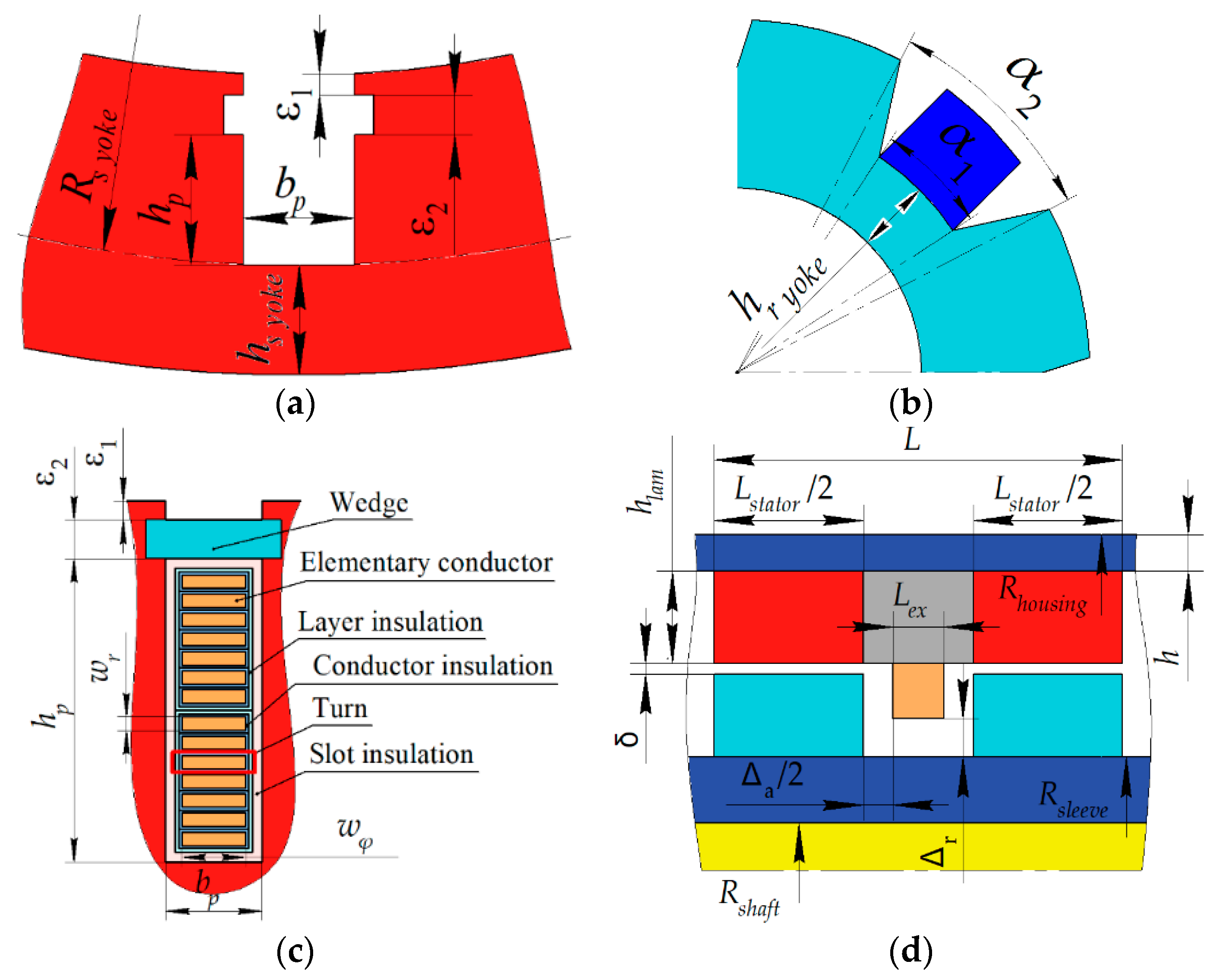
Table 1 shows some of the key SHG parameters that are not changed during optimization. Table 2 shows the SHG parameters that are varied during optimization. Because the Nelder-Mead method is an unconstrained optimization method, ranges of optimization parameters are not provided. It is assumed that the shaft does not conduct any flux. The cross sections of the stator housing and the rotor sleeve conducting the same axial excitation flux are taken equal, therefore, a change in the thickness of the stator housing also causes a change in the outer diameter of the rotor sleeve. When the thickness of the stator housing changes, the outer diameter of the stator lamination also changes.
The width and height of the rectangular armature winding wire wx and wy, necessary to determine the DC and AC (eddy current) losses in the armature winding, are determined based on the dependencies [5]:
where ax = 1.51 mm, ay = 1.8 mm, Δw = 0.31 mm are determined by thicknesses of the conductor insulation and slot insulation.
bp = wx + ax; hp = 2∙(wy + Δw) ∙ Nsec + ay,
The net copper fill factor of the excitation winding area is used to calculate the losses in this winding and is assumed to be 0.8. Only DC losses in the excitation winding are taken into account. As Table 2 shows, when optimizing, the electrical angle between the middle of the rotor tooth and the stator current vector ("current angle") at a speed of 3450 rpm varies. That angle at operating point of 750 rpm is assumed to be 40.1 electrical radians. Since the housing and the rotor sleeve carry out the same flux, the areas of their cross-sections are assumed to be equal.

Table 1.
Some of the SHG parameters that do not change during optimization.
| Parameter | Value |
| Machine length without end winding parts L, mm | 150 |
| Stator housing outer diameter, mm | 370 |
| Axial clearance between excitation winding and rotor, Δa, mm | 15 |
| Radial clearance between field winding and rotor Δr, mm | 12 |
| Shaft diameter, mm | 40 |
| Stator lamination yoke Hstator yoke, mm | 12 |
| Rotor lamination yoke Hrotor yoke, mm | 9 |
| Stator wedge thickness, ε2, mm | 1 |
| Stator unfilled area thickness, ε1, mm | 1 |
| Angle of field weakening at 750 rpm, electrical radian | 0.1 |
| Laminated steel grade | 2412 |
| Laminated steel thickness, mm | 0.35 |
Table 2.
Initial and optimized vectors of the variable optimization parameters.
| Parameter | Initial design, x0 | Optimized design, x |
| Housing thickness h, mm | 15 | 11.07 |
| Total stator stacks length Lstator, mm | 130 | 128.3 |
| Stator slot depth hp, mm | 20 | 27.9 |
| Stator slot width bp, mm | 5 | 6.37 |
| Airgap width δ, mm | 2 | 0.91 |
| Rotor slot thickness, α1 | 0.5∙tz* | 0.481∙tz* |
| Rotor slot thickness, α2 | 0.6∙tz* | 0.689∙tz* |
| Angle of field weakening at 3450 rpm, electrical radian | 0.6 | 0.93 |
| Current ratio** @750rpm | 8 | 14.54 |
| Current ratio** @3450rpm | 8 | 9.76 |
Notes: * the rotor tooth pitch tz = 360°/6 = 60 mechanical degrees; ** the current ratio is the ratio of the current in the armature winding layer to the current in the excitation winding.
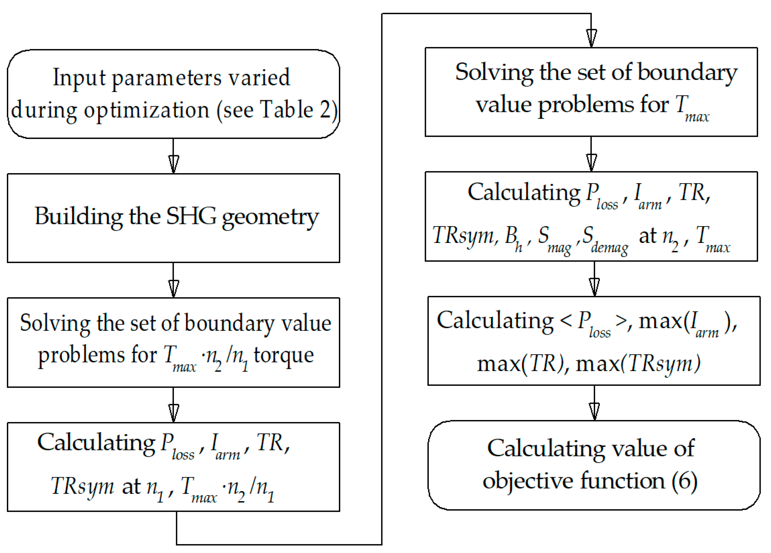
Figure 6 shows a flowchart of the calculation of the output of the objective function (6). To find the optimized value of the vector of variable parameters x, the fminsearch(F, x0) MATLAB procedure is launched, where F is the objective function, according to Figure 6; x0 is the initial vector of variable optimization parameters (see Table 2). The details of the optimization function ‘fminsearch’, which implements the simplex gradientless Nelder-Mead method [27], are well known and described in the documentation of the MATLAB software [29].
Figure 6.
Objective function flowchart.
5. Optimization Results
The application of the Nelder-Mead method leads to the convergence of the objective function (6) to a certain minimum (Figure 7). The volume of the simplex can quickly decrease during optimization, and further optimization slows down. Therefore, after the 180th function call, the Nelder-Mead method was restarted. The found optimal solution was used as the initial approximation. The linear dimensions of the simplex at the restart were reduced by 4 times compared to the initial simplex. One function call takes approximately 20 minutes using a laptop with 2 cores, 2.70 GHz processor and 16GB of RAM.
In the course of optimization, the SHG average loss (Figure 8a) and the armature current amplitude (Figure 8b) were also reduced significantly. The nonsymmetrized torque ripple, that has the smallest power in the objective function (6), increased during the optimization (Figure 9a). However, the symmetrized torque ripple, which is the resultant one of the SHG as a whole, slightly decreased after the optimization (Figure 9b), which indicated that the torque waveforms of the individual SRSCs are in opposite phase and cancel each other out. Figure 10 and Figure 11 show the geometry and 2D flux density plot of an SRSC before the first start of the optimization procedure and after optimization, correspondingly. Table 3 compares the performances of the SHG with ferrite magnets before and after optimization.
Figure 7.
Change in the value of the objective function (6) in the course of optimization.
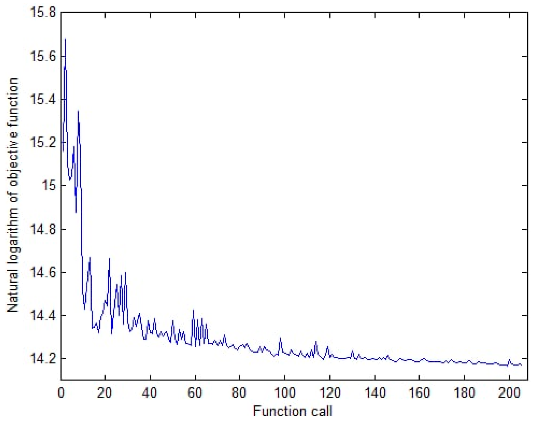
Figure 8.
Change of the generator parameters during optimization: (a) Average losses; (b) Maximum magnitude of the armature winding current.
Figure 8.
Change of the generator parameters during optimization: (a) Average losses; (b) Maximum magnitude of the armature winding current.

Figure 9.
Change of the generator parameters during optimization: (a) Nonsymmetrized torque ripple; (b) Symmetrized torque ripple.
Figure 9.
Change of the generator parameters during optimization: (a) Nonsymmetrized torque ripple; (b) Symmetrized torque ripple.
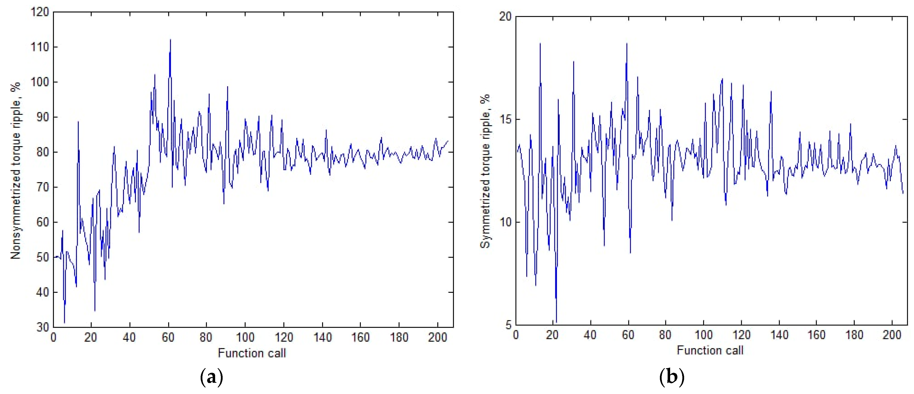
Figure 10.
The cross-section of the SHG initial design and its plot of flux density magnitude; areas of extreme saturation (> 2T) are colored white: (a) at 3450 rpm; (b) at 750 rpm.
Figure 10.
The cross-section of the SHG initial design and its plot of flux density magnitude; areas of extreme saturation (> 2T) are colored white: (a) at 3450 rpm; (b) at 750 rpm.
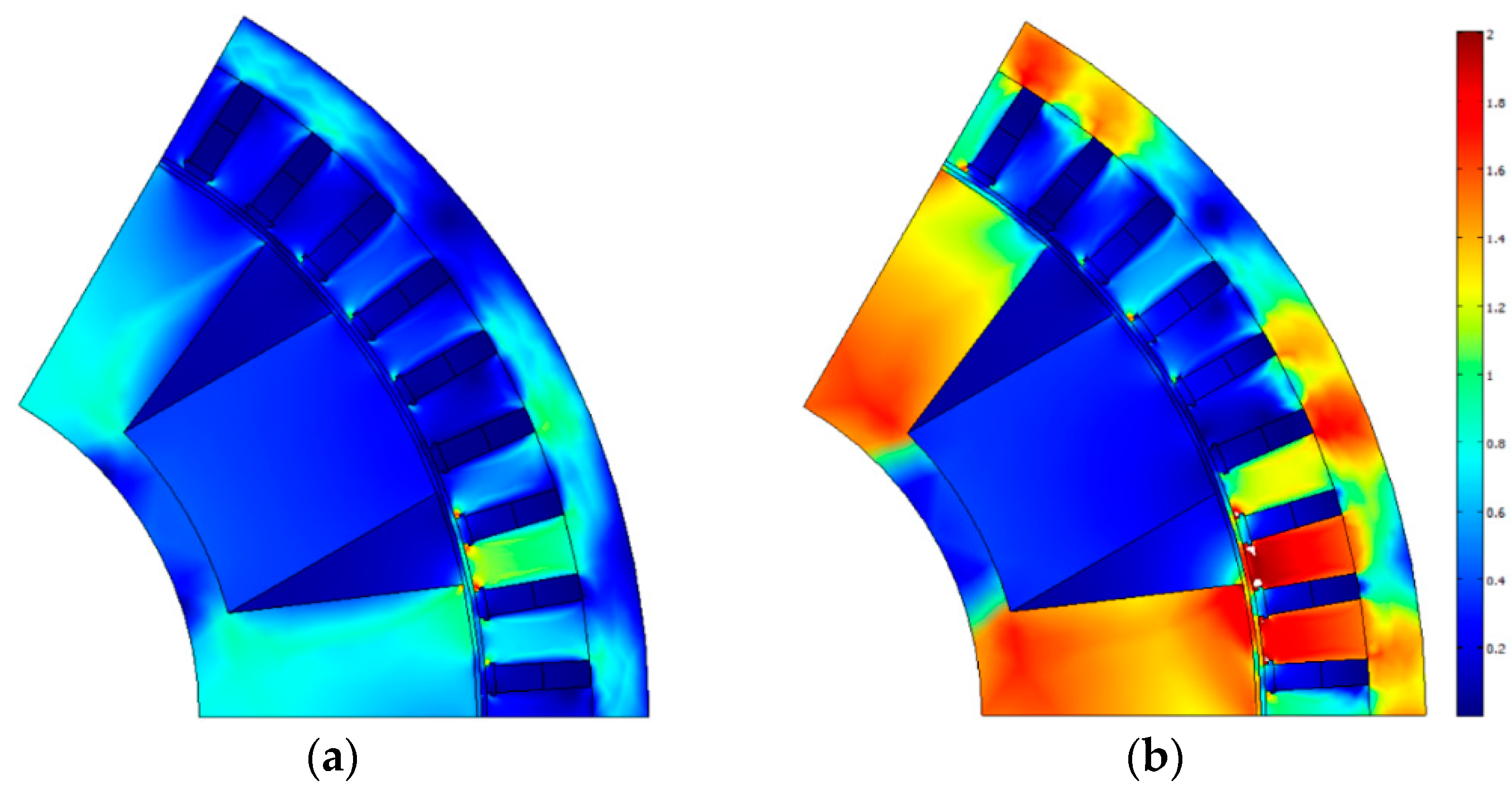
Figure 11.
The cross-section of the SHG optimized design and its plot of flux density magnitude; areas of extreme saturation (> 2T) are colored white: (a) at 3450 rpm; (b) at 750 rpm.
Figure 11.
The cross-section of the SHG optimized design and its plot of flux density magnitude; areas of extreme saturation (> 2T) are colored white: (a) at 3450 rpm; (b) at 750 rpm.
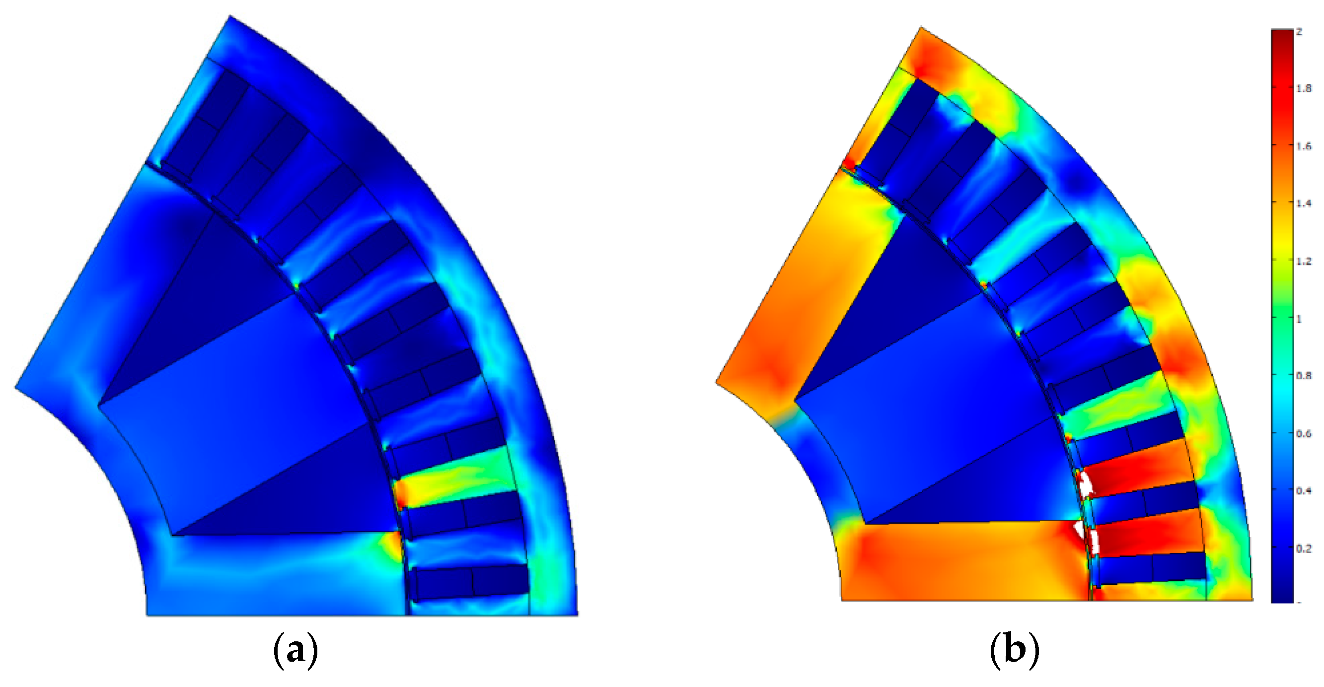
Figure 12.
Demagnetizing force (kOe) in the area of the permanent magnet at 750 rpm: (a) Before optimization, minimum value is -3.0 kOe; (b) After optimization, minimum value is -2.9 kOe.
Figure 12.
Demagnetizing force (kOe) in the area of the permanent magnet at 750 rpm: (a) Before optimization, minimum value is -3.0 kOe; (b) After optimization, minimum value is -2.9 kOe.

Comparison of Figure 10 And Figure 11 Shows that as a result of optimization, the height and area of the stator slots has increased significantly. The air gap has become much smaller. The thickness of the rotor teeth and the thickness of the magnets in the rotor slots have been significantly reduced. Comparison of Figure 12a and Figure 12b shows that as a result of the optimization, the maximum demagnetizing force has been reduced from 3 kOe to about 2.9 kOe, while the coercive force of the magnets is greater than 3.9 kOe. It can be concluded that the proposed design does not create a risk of demagnetization of the permanent magnets.
Figure 13 Shows the torque ripple of the rotor and stator stack pairs and the output torque ripple at the 750 rpm and 3450 rpm after optimization. It can be seen that although the torque ripple of each pair is rather high, these torque ripples are in antiphase. As a result, the output torque ripple is much less than ones of the individual pairs.
Figure 13.
The torque ripple of the individual SRSC and the symmetrized (output) torque ripple after optimization: (a) at 3450 rpm; (b) at 750 rpm.
Figure 13.
The torque ripple of the individual SRSC and the symmetrized (output) torque ripple after optimization: (a) at 3450 rpm; (b) at 750 rpm.
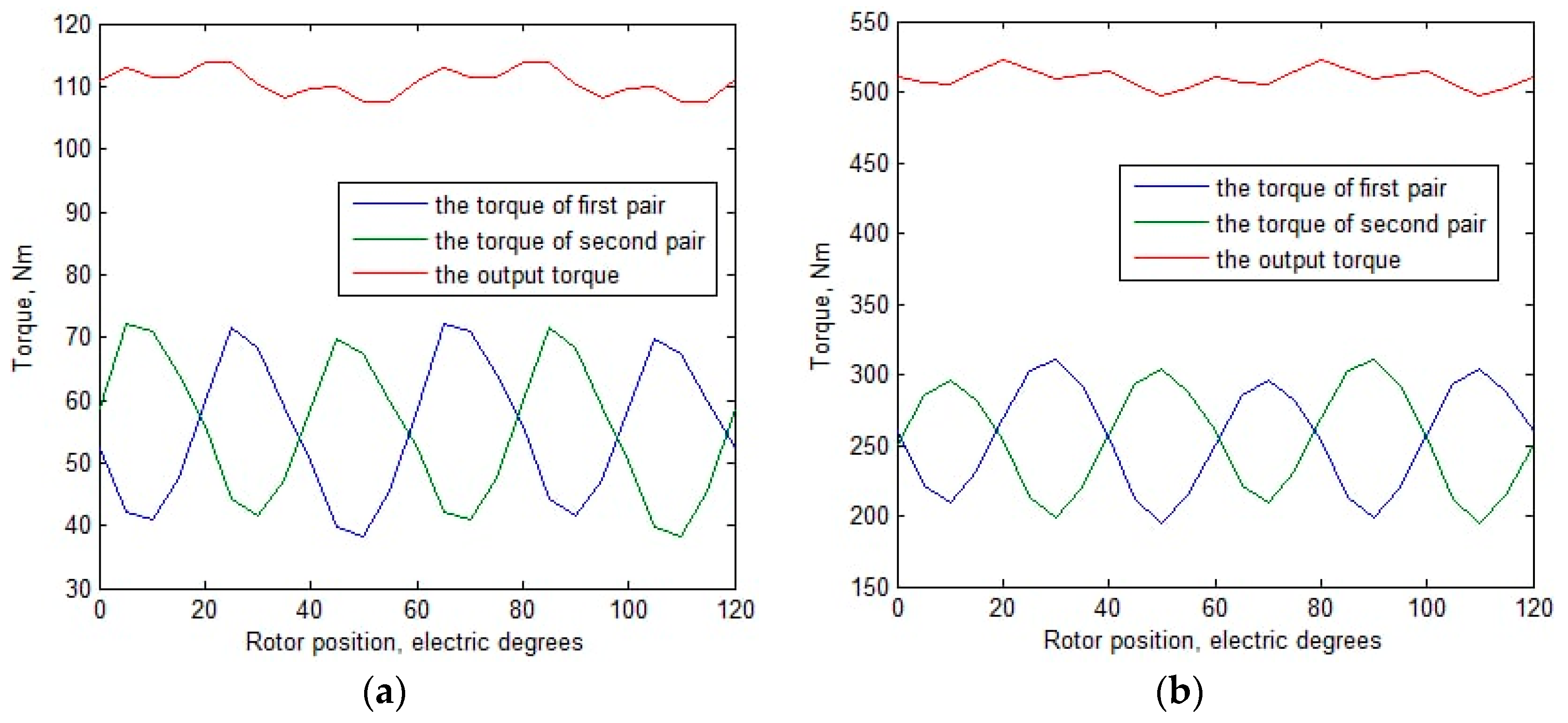
Table 3.
Optimization results.
| Parameter | Initial design | Optimized design | ||
| Operating point | 1 | 2 | 1 | 2 |
| Rotational speed n, rpm | 3450 | 750 | 3450 | 750 |
| Amplitude of the armature phase current Iarm, A | 390.9 | 957.7 | 392.8 | 720.5 |
| Efficiency, %* | 93.8 | 74.4 | 91.4 | 81.4 |
| Input mechanical power Pmech, kW | 40 | 40 | 40 | 40 |
| Shaft torque, N∙m | 111 | 510 | 111 | 510 |
| Output electrical power P1, kW | 37.64 | 30.49 | 36.87 | 33.49 |
| Armature DC copper loss Parm DC, kW | 1.51 | 9.07 | 1.77 | 5.95 |
| Armature eddy-current copper loss Parm AC, W | 133 | 56 | 417 | 143 |
| Stator lamination loss Piron st, W | 669 | 372 | 811 | 396 |
| Rotor lamination loss Piron rt, W | 52 | 11 | 139 | 22 |
| Excitation copper loss Pex, W | 127 | 743 | 290 | 934 |
| Total loss Ploss, kW** | 2.49 | 10.26 | 3.43 | 7.45 |
| Average losses, kW | 6.37 | 5.44 | ||
| Number of turns in armature winding | 5.06 | 7.08 | ||
| Required rectifier power, kW | 95.6 | 67.5 | ||
| Power factor | 0.969 | 0.695 | 0.998 | 0.764 |
| Line-to-line voltage amplitude Varm, V | 115.3 | 53.5 | 108.2 | 70.2 |
| Nonsymmetrized torque ripple, % | 49.8 | 35.6 | 84.4 | 44.9 |
| Symmetrized torque ripple, % | 13.2 | 5.5 | 10.8 | 3.5 |
| Magnetic flux density in the housing and sleeve, T | 1.00 | 1.88 | 0.86 | 1.60 |
Notes: * the generator efficiency was calculated as η = (P1 − Pex)/Pmech, where P1 is the active power in armature winding; Pex is the losses in the excitation winding; Pmech is the input (mechanical) power. Mechanical losses, namely bearing and windage losses, are neglected; ** the total loss is the sum of all individual loss components Ploss = Parm DC + Parm AC + Piron st + Piron rt + Pex.
Comparison of the SHG parameters before and after optimization, shown in Table 3 allows us to draw the following conclusions:
- Average losses were reduced by 100%(6.37 – 5.44)/6.37 = 14.6%;
- After optimization, the maximum current at the maximum speed becomes was reduced by 100%(957.7 – 720.5)/ 957.7 = 24.8%;
- After optimization, the maximum symmetrized torque ripple (ripple at the shaft at low speed was reduced by 100% (13.2 – 10.8)/13.1 = 18.2%;
- The optimized SHG with ferrite magnets is more saturated than the initial one. However, the risk of demagnetization of ferrite magnets does not increase due to the fact that the increase in the height of the magnet after optimization compensates for the increased MMF of the excitation coil;
- After optimization, due to the soft restriction introduced in function (6), the flux density in the non-laminated parts does not exceed 1.6 T.
- The coercive force of the Y30H-2 magnet is 3.9 kOe, which is much greater than the demagnetizing magnetic field in the optimized design.
6. Comparison of SHG with Ferrite Magnets and SHG without Magnets
This section discusses the comparison between the SHG with ferrite magnets, which characteristics are presented in this article, and the SHG without magnets, which characteristics were calculated in our previous study [24]. To avoid repetition in this article, in Table 5 we present only the final optimized characteristics of the SHG without magnets. Details of the SHG design without magnets and its optimization can be found in [24]. Table 4 shows a comparison of the performances of the optimized SHG designs with ferrite magnets and without magnets. Table 5 shows a comparison of the dimensions, masses, and costs of active materials for the compared generators.
Table 4.
Comparison of the SHG with ferrite magnets and SHG without magnets.
| Parameter | SHG without magnets | SHG with ferrite magnets | ||
| Operating point number, i | 1 | 2 | 1 | 2 |
| Rotational speed n, rpm | 3450 | 750 | 3450 | 750 |
| Amplitude of the armature phase current Iarm, A | 369.5 | 676.2 | 392.8 | 720.5 |
| Efficiency, % | 90.4 | 79.8 | 91.4 | 81.4 |
| Input mechanical power Pmech, kW | 40 | 40 | 40 | 40 |
| Shaft torque, N∙m | 111 | 510 | 111 | 510 |
| Output electrical power P1, kW | 36.58 | 33.12 | 36.87 | 33.49 |
| Armature DC copper loss Parm DC, kW | 1.90 | 6.37 | 1.77 | 5.95 |
| Armature eddy-current copper loss Parm AC, W | 417 | 131 | 417 | 143 |
| Stator lamination loss Piron st, W | 961 | 403 | 811 | 396 |
| Rotor lamination loss Piron rt, W | 192 | 26 | 139 | 22 |
| Excitation copper loss Pex, W | 368 | 1169 | 290 | 934 |
| Total loss Ploss, kW | 3.84 | 8.10 | 3.43 | 7.45 |
| Average losses | 5.97 | 5.44 | ||
| Number of turns in armature winding | 7.75 | 7.08 | ||
| Required rectifier power, kW | 67.9 | 67.5 | ||
| Power factor | 1.000 | 0.747 | 0.998 | 0.764 |
| Line-to-line voltage amplitude Va, V | 116.0 | 75.3 | 108.2 | 70.2 |
| Nonsymmetrized torque ripple, % | 97.8 | 47.0 | 84.4 | 44.9 |
| Symmetrized torque ripple, % | 11.3 | 4.5 | 10.8 | 3.5 |
| Magnetic flux density in the housing and the sleeve, T | 0.84 | 1.60 | 0.86 | 1.60 |
Table 5.
Comparison of masses, costs, and dimensions of parts of the SHG without magnets and with ferrite magnets.
Table 5.
Comparison of masses, costs, and dimensions of parts of the SHG without magnets and with ferrite magnets.
| Parameter | SHG without magnets | SHG with ferrite magnets |
| Stator lamination mass, kg | 34.2 | 28.0 |
| Rotor lamination mass, kg | 15.6 | 17.1 |
| Armature copper mass, kg | 17.8 | 14.7 |
| Excitation copper mass, kg | 2.44 | 2.62 |
| Magnets mass, kg | - | 7.88 |
| Weight of the rotor sleeve and SHG housing without bearing shields, kg | 53.2 | 29.2 |
| Total mass of the active materials, rotor sleeve and SHG housing, kg | 123.24 | 99.5 |
| Stator lamination cost, USD | 34.2 | 28.0 |
| Rotor lamination cost, USD | 15.6 | 17.1 |
| Armature copper cost, USD | 124.6 | 102.9 |
| Excitation copper cost, USD | 17.1 | 18.3 |
| Magnets cost, USD | - | 145.5 |
| Rotor sleeve and SHG housing cost, USD | 53.2 | 29.2 |
| The total cost of the active materials (electrical steel, copper, permanent magnets) and structural steel of the rotor sleeve and SHG housing, USD* | 244.7 | 341.0 |
| Total length of the stator lamination, mm | 152.7 | 128.3 |
| Total length of the machine excluding the winding end parts (including spaces for the excitation coils), mm | 180 | 150 |
| Stator lamination outer diameter, mm | 370 | 370 |
| Air gap, mm | 0.88 | 0.91 |
* Note: the following material costs are assumed: copper—USD 7/kg, laminated electrical steel—USD 1/kg; non-laminated structural steel for the housing and rotor sleeve—USD 1/kg; Y30H-2 grade ferrite magnets—USD 18.46/kg [30].
Comparing the characteristics of the SHGs without permanent magnets and with ferrite magnets, shown in Table 5 and Table 6, the following findings can be reported:
1. Average losses for the SHG with ferrite magnets are less than for the SHG without magnets by 100%(5.97-5.44)/5.97 = 8.9%;
2. The maximum current for the SHG with ferrite magnets is slightly higher than that for the SHG without magnets, by 100%(720.5-676.2)/676.2 = 6.6%. This is due to the fact that the optimization result is a compromise between the minimum losses and the minimum current, and the losses < Ploss > in the objective function (6) have a larger weight coefficient.
3. The maximum output torque ripple of the SHG with ferrite magnets is less than that of the SHG without magnets by 100%(11.3-10.8)/11.3 = 4.4% due to the increased air gap;
4. An SHM without magnets allows the control technique in which the current ratio is equal throughout the entire constant mechanical power speed range (CPSR). In an SHM with (ferrite) magnets, the magnets contribution in the machine excitation does not reduce at high speed. Therefore, the excitation current must decrease more rapidly than armature current does with an increase of speed. In the considered SHG with ferrite magnets, the current ratio at 3450 rms is 1.5 times less than that at 750 rpm;
5. The total length excluding the armature winding end parts, including the width of the excitation winding, for the SHG with ferrite magnets is less than for the SHG without magnets, by 100% (180-150) / 150 = 16.7%;
6. The weight of the rotor sleeve and housing of the SHG with ferrite magnets is about two times less than that of the SHG without magnets. This is so, firstly, because the ferrite magnets contribute to the excitation field, and therefore the field of the excitation winding can be reduced. Secondly, the magnetic fluxes created by the ferrite magnets and the excitation winding have opposite directions in the non-laminated parts (the rotor sleeve and housing). Therefore, the saturation of the non-laminated parts is reduced, and the housing of the SHG with ferrites becomes thinner than that of the SHG without magnets.
7. The total mass of active materials including the rotor sleeve and the generator housing for the SHG with ferrite magnets is 100% (123.24-99.5)/ 23.24 = 19.3% less than the mass of the SHG without magnets;
8. When the car battery is discharged, the power supply of the excitation winding of the SHG without magnets is lost, and there is a risk that the generator cannot be started due to lack of excitation. In the undercar SHG with ferrite magnets, even in the absence of current in the excitation winding, some excitation is created by permanent magnets. Therefore, even with a discharged car battery, SHG with ferrite magnets can provide the car with energy and recharge the battery.
9. The total cost of the active materials (electrical steel, copper, permanent magnets) and structural steel of the rotor sleeve and stator housing for the SHG with ferrite magnets is 341/244.7 = 1.4 times more than that of the SHG without magnets, primarily due to the addition of the cost of ferrite magnets.
10. In general, as a result of comparing the characteristics of the SHGs with ferrite magnets and without magnets, it can be concluded that the use of the SHG with ferrite magnets in this application is promising, since the efficiency of the generator has been improved significantly, the dimensions and weight have also been significantly reduced, with a relatively small increase in cost.
7. Conclusions
This article discusses the procedure and results of optimizing a 35 kW synchronous homopolar generator (SHG) with ferrite magnets for railway passenger cars. The generator characteristics are optimized taking into account the required CPSR. The single-criterion unconstrained Nelder-Mead algorithm and the two-dimensional finite element method are used.
The following optimization objectives were selected: decreasing the average losses over the CPSR, decreasing the installed power capacity of the solid-state rectifier, and the reduction of the torque ripple. As a result of optimization, the characteristics of the generator have been significantly improved. Compared to the non-optimized design, the following were reduced: average generator loss by 14.6%, upper limit of the solid-state rectifier current by 24.8%, symmetrized (output) torque ripple by 18.2%.
The nonsymmetrized torque ripple, that has the smallest power in the objective function (6), increased during the optimization. However, the symmetrized torque ripple, which is the resultant one of SHG as a whole, decreased slightly after the optimization, indicating that the torque waveforms of the individual SRSCs are in opposite phase and cancel each other out.
Based on the results of the optimization, the characteristics obtained is compared with an SHG without permanent magnets optimized by the same method.
The comparison of the characteristics of the SHGs with ferrite magnets and without magnets shows that the SHG with ferrite magnets has significant advantages: average generator loss is reduced by 8.9%, torque ripple is reduced by 4.4%, the total mass of the active materials, rotor sleeve and generator housing is reduced by 19.3%, the overall length is reduced by 16.7%. The upper-limit current for the SHG with ferrite magnets is slightly higher than that for the SHG without magnets, by 6.6%. The advantage of the SHG without magnets is that the cost is 1.4 times less, since it does not use ferrite magnets.
In general, as a result of comparing the characteristics of the SHGs with ferrite magnets and without magnets, it can be concluded that the use of the SHG with ferrite magnets in this application is promising, since the efficiency of the generator has been improved significantly, the dimensions and weight have also been significantly reduced, with a relatively small increase in cost.
Author Contributions
Conceptual approach, V.D. and V.P.; data curation, V.D. and V.K.; software, V.D. and V.P.; calculations and modeling, V.D., V.K. and V.P.; writing—original draft, V.D., V.K. and V.P.; visualization, V.D. and V.K.; review and editing, V.D., V.K. and V.P. All authors have read and agreed to the published version of the manuscript.
Funding
The research funding from the Ministry of Science and Higher Education of the Russian Federation (Ural Federal University Program of Development within the Priority-2030 Program) is gratefully acknowledged.
Institutional Review Board Statement
Not applicable.
Informed Consent Statement
Not applicable.
Data Availability Statement
Data are contained within the article.
Acknowledgments
The authors thank the editors and reviewers for careful reading and constructive comments.
Conflicts of Interest
The authors declare no conflict of interest.
References
- Jung, S.; Jung, H.; Hahn, S.; Jung, H.; Lee, C. Optimal Design of Direct-Driven PM Wind Generator for Maximum Annual Energy Production. IEEE Trans. Magn. 2008, 44, 1318–1338. [Google Scholar] [CrossRef]
- Lima, I.; Filho, W. Rare Earth Industry; Elsevier: Amsterdam, The Netherlands, 2015. [Google Scholar]
- Fang, S.; Wang, Y.; Liu, H. Design study of an aerospace motor for more electric aircraft. IET Electric Power Applications 2020, 14 (14), 2881–2890. [Google Scholar] [CrossRef]
- Liaw, C.; Soong, W. ; Welchko. B.; Ertugrul, N. Uncontrolled generation in interior permanent-magnet Machines. IEEE Trans. Ind. Appl. 2005; 41 (4), 945–954. [Google Scholar] [CrossRef]
- Prakht, V.; Dmitrievskii, V.; Kazakbaev, V.; Anuchin, A. Comparative Study of Electrically Excited Conventional and Homopolar Synchronous Motors for the Traction Drive of a Mining Dump Truck Operating in a Wide Speed Range in Field-Weakening Region. Mathematics 2022, 10, 3364. [Google Scholar] [CrossRef]
- Kutt, F.; Michna, M.; Kostro, G. Non-Salient Brushless Synchronous Generator Main Exciter Design for More Electric Aircraft. Energies 2020, 13, 2696. [Google Scholar] [CrossRef]
- Noeland, J.; Nuzzo, S.; Tessarolo, A.; Alves, E. Excitation System Technologies for Wound-Field Synchronous Machines: Survey of Solutions and Evolving Trends. IEEE Access 2019, 7, 109699–109718. [Google Scholar] [CrossRef]
- Bindu, G.; Basheer, J.; Venugopal, A. Analysis and control of rotor eccentricity in a train-lighting alternator. In Proceedings of the 2017 IEEE International Conference on Power, Control, Signals and Instrumentation Engineering (ICPCSI), Chennai, India, 21–22 September 2017; pp. 2021–2025. [Google Scholar] [CrossRef]
- Lorilla, L.; Keim, T.; Lang, J.; Perreault, D. Topologies for future automotive generators. Part I. Modeling and analytics. In Proceedings of 2005 IEEE Vehicle Power and Propulsion Conference, Chicago, USA, 7 September 2005; pp. 74–85. [Google Scholar] [CrossRef]
- Bianchini, C.; Immovilli, F.; Bellini, A.; Lorenzani, E.; Concari, C.; Scolari, M. Homopolar generators: An overview. In Proceedings of the 2011 IEEE Energy Conversion Congress and Exposition, Phoenix, AZ, USA, 17–22 September 2011; pp. 1523–1527. [Google Scholar] [CrossRef]
- Severson, E.; Nilssen, R.; Undeland, T.; Mohan, N. Dual-purpose no-voltage winding design for the bearingless AC homopolar and consequent pole motors. IEEE Trans. Ind. Appl. 2005; 51 (4), 2884–2895. [Google Scholar]
- Jeong, J.-S.; An, D.-K.; Hong, J.-P.; Kim, H.-J.; Jo, Y.-S. Design of a 10-MW-Class HTS homopolar generator for wind turbines. IEEE Trans. Appl. Supercond. 2017; 27 (4), 1–4. [Google Scholar]
- Cheshmehbeigi, H.; Afjei, E. Design optimization of a homopolar salient-pole brushless DC machine: Analysis, simulation, and experimental tests. IEEE Trans. Energy Convers. 2013; 28 (2), 289–297. [Google Scholar]
- Severson, E.; Mohan, N.; Nilssen, R.; Undeland, T. Outer-rotor AC homopolar motors for flywheel energy storage. Proceedings of 7th IET Int. Conf. Power Electron., Mach. Drives (PEMD), Manchester, U.K., 8-10 April 2014; pp. 1–6. [Google Scholar]
- Yang, J.; Ye, C.; Liang, X.; Xu, W.; Xiong, F.; Xiang, Y.; Li, W. Investigation of a Two-Dimensional Analytical Model of the Homopolar Inductor Alternator. IEEE Trans. Appl. Supercond. 2018; 28 (3), 1–5. [Google Scholar]
- Dmitrievskii, V.; Prakht, V.; Anuchin, A.; Kazakbaev, V. Traction Synchronous Homopolar Motor: Simplified Computation Technique and Experimental Validation. IEEE Access 2020, 8, 185112–185120. [Google Scholar] [CrossRef]
- Ye, C.; Yang, J.; Xiong, F.; Zhu, Z.Q. Relationship between homopolar inductor machine and wound-field synchronous machine. IEEE Trans. Ind. Electron. 2020, 67, 919–930. [Google Scholar] [CrossRef]
- Belalahy, C.; Rasoanarivo, I.; Sargos, F. Using 3D reluctance network for design a three phase synchronous homopolar machine. In Proceedings of the 2008 34th Annual Conference of IEEE Industrial Electronics. Orlando, USA, 10-13 November 2008; pp. 2067–2072. [Google Scholar]
- Kalsi, S.; Hamilton, K.; Buckley, R.G.; Badcock, R.A. Superconducting AC Homopolar Machines for High-Speed Applications. Energies 2019, 12, 86. [Google Scholar] [CrossRef]
- Design optimization of a homopolar salient-pole brushless DC machine: Analysis, simulation, and experimental tests / H. Cheshmehbeigi, E. Afjei // IEEE Transactions on Energy Conversion. − 2013. − V. 28. − № 2. − P. 289–297. [CrossRef]
- Janis, D.; Levin, N.; Orlova, S.; Pugachov, V.; Ribickis, L.; Optimization of the magnetic circuit of an axial inductor machine based on the calculation and analysis of magnetic field. In 2009 13th European Conference on Power Electronics and Applications, Barcelona, Spain, 8-0 September 2009, pp. 1-8. Available online: https://ieeexplore.ieee.org/document/5278726 (accessed on 12 January 2022).
- Orlova, S.; Pugachov, V.; Levin, N. Hybrid Excitation of the Axial Inductor Machine. Latv. J. Phys. Tech. Sci. 2012, 49, 35–41. [Google Scholar] [CrossRef]
- Ketner, K.; Dirba, J.; Levins, N.; Orlova, S.; Pugachev, V. Inductor machine with axial excitation. LV Patent LV13971B, 20 November 2009. (in Latvian). [Google Scholar]
- Dmitrievskii, V.; Prakht, V.; Kazakbaev, V. Synchronous Homopolar Generator without Permanent Magnets for Railway Passenger Cars. Mathematics. 2023. Under review.
- Guo, S.; Yi, Z.; Liu, P.; Wang, G.; Lai, H.; Yu, K.; Xie, X. Analysis and Performance Evaluation of a Novel Adjustable Speed Drive with a Homopolar-Type Rotor. Mathematics 2022, 10, 3712. [Google Scholar] [CrossRef]
- Synchronous generators type EGV. The generators EGV are designed for power supply of a passenger car. Characteristics. Available online: https://www.pemz.ru/catalog/dlya_zheleznoy_dorogi/Synchronous_generators_type_EGV/ (accessed on 15 December 2022).
- Nelder, J.; Mead, R. A Simplex Method for Function Minimization. Comput. J. 1965, 7, 308–313. [Google Scholar] [CrossRef]
- IEC. Specifications for Particular Types of Winding Wires—Part 0-2: General Requirements—Enamelled Rectangular Copper Wire; IEC 60317-0-2:2020; IEC: Geneva, Switzerland, 2020; Available online: https://webstore.iec.ch/publication/63495 (accessed on 15 December 2022).
- Find minimum of unconstrained multivariable function using derivative-free method. MATLAB documentation. © 1994-2023 The MathWorks, Inc. Available online: https://www.mathworks.com/help/matlab/ref/fminsearch.html (accessed on 18 January 2022).
- Hard ferrite magnets, product information, IBSMagnet. 2020, Available online:. Available online: https://ibsmagnet.com/products/dauermagnete/hartferrit.php (accessed on 13 January 2022).
Disclaimer/Publisher’s Note: The statements, opinions and data contained in all publications are solely those of the individual author(s) and contributor(s) and not of MDPI and/or the editor(s). MDPI and/or the editor(s) disclaim responsibility for any injury to people or property resulting from any ideas, methods, instructions or products referred to in the content. |
© 2023 by the authors. Licensee MDPI, Basel, Switzerland. This article is an open access article distributed under the terms and conditions of the Creative Commons Attribution (CC BY) license (http://creativecommons.org/licenses/by/4.0/).
Copyright: This open access article is published under a Creative Commons CC BY 4.0 license, which permit the free download, distribution, and reuse, provided that the author and preprint are cited in any reuse.


