
Submitted:
19 January 2023
Posted:
20 January 2023
You are already at the latest version
Abstract
IoT is a computational perception that defines a situation, where smart objects are interconnected to the internet/ network. In the last few years, IoT objects have increased in all sectors/ fields and use in all domains of our lives. As the number of devices increases, the privacy of data becomes an important issue. To deal with this issue different techniques have been used by researchers in this field. Unfortunately, these methods have less traceability, privacy of data, and accountability. This paper aims to design a blockchain-based network architecture for Traceability, Data privacy, and Accountability (TDA). Technologies of blockchain are known as a distributed ledger of transactions record, which record the life span information with a timestamp. The major features of blockchain are persistency, decentralization, and audibility. These features help to decrease the budget and increase efficiency. Moreover, to strengthen the TDA architecture, this paper also discusses the performance of the proposed architecture.
Keywords:
Blockchian
; IoT
; CoAP
; MQTT
; REST: Traceability
I. INTRODUCTION
IoT is a new pattern, but the idea of utilizing computer systems and networks for observing or monitoring devices has been existing for years. For example, schemes to observe electrical grid meters by making use of telephone lines remotely, stood commercially used from the 1970s [16].
In 1990[17], improvement in the technology of wireless assisted machine-to-machine (M2M) and solutions to the industrial problem, to get acceptance permitting tools to be observed. M2M depends on particular industry standards and networks. Hence, it leads to the Internet Protocol (IP) standard use to link IoT components. This present, (a toaster) the 1st IP supported component or instrument capable of a turn-on to start and a turn-off to stop working through the Internet.
In the modern era technologies have transformed the standards of our life. This is due to inventions in technologies, which provide certification to devices for interconnection through an IoT network. The information collected from this network helps to make an efficient decision. This is known as Internet-of-Things (IoT) [13].
In [18] Cisco predicts the internet of things as encompassing things, people, and places, which makes services accessible for other objects to use. An example is the Thermostat-Nest [11] mounted in homes to remotely change their room temperature. These IoT instruments help to makes ease for house owners.
Moreover, IoT instruments are used in industries for maintenance. Therefore sensors and cameras are used in business for collection of data that’s is utilized for decision making to stop unnecessary actions [3]. Because IoT helps for data collection and decision making, it is used in daily actions or working.
Based on International Data Corporation (IDC) report, 20% of IoT companies use basic services of blockchain technology and 75% of all IoT vendors improve the security features that make these additional smart for customers [19].
Due to diverse incorporation of services and IoT network, the information records on instruments are exposed to attackers by misusing the components in related IoT networks. Furthermore, without permission an intruder can get access to the information. The distribution of information between the components via the IoT network that uses the communication protocols. The “things” differ from wearable to large machines which consist of sensor chips [5]. However presently IoT components are interconnected via the central Client-Server Model which causes different security issues in IoT networks.
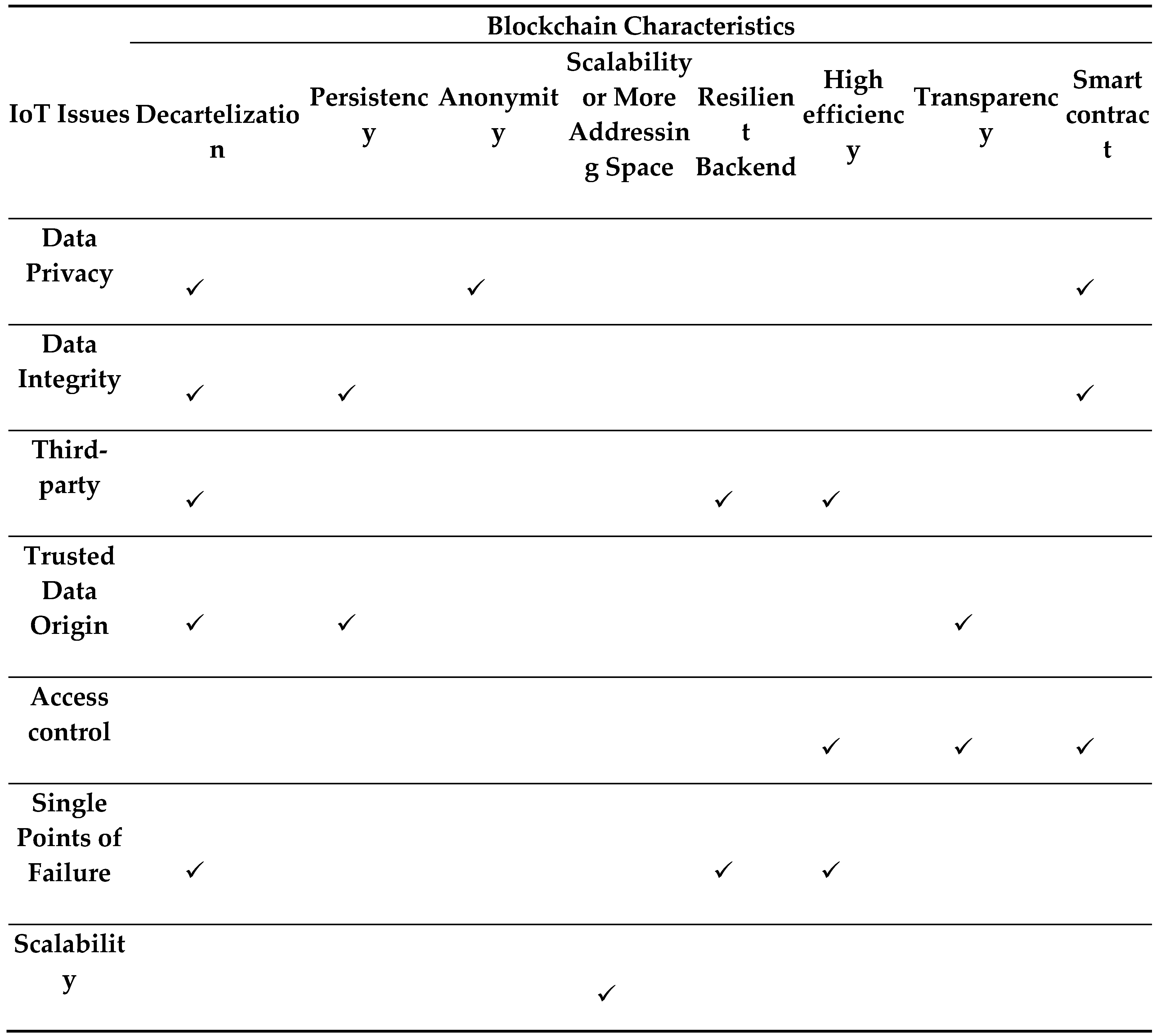
A lot of techniques by many researchers in recent years have been proposed for Traceability, data privacy, and accountability. But, still some gaps in the existing studies. In recent years the technology of blockchain is introduced that has many features to present the solution of problems that occur in IoT network devices. Blockchain records the life span of all IoT devices. Proof of work is used among the network components to remove a centralized third party. That is helpful to solve the problems of security in IoT as in Table1 [1]. Therefore this paper aims to use the blockchain for presenting the solutions of Traceability, data privacy, and accountability issues.
The primary purpose of this paper is to design a decentralized solution. That is used to make sure traceability, data privacy, and accountability (TDA) insides the network architecture of the Internet of Things. The main motive behindhand is to deliver the user privacy and accountability for actions takes place insides the IoT network. At the point of time whenever any user wants to access the data of the user or may make any alteration with transactions record, their traceability must be guaranteed about appropriate audit-ability. So, the instruments and users are accountable for their activities.
This paper is organized into sections, section I discuses about the background, introduction and problem statement. Related studies are described in section II. The proposed framework and its description are discussed in section III. Moreover in section IV implementation and results are discussed. Finally in section V Conclusion and future work are described.
A. Problem Definition
IoT devices are an important part of smart society such as power stations of electricity and hospitals where peoples share their data for doing any task. The information of users is more sensitive in such fields. In resources, constraint environment devices have limited processing capability, bandwidth, and memory. To perform high-level functionalities IoT devices using the internet interconnected with each other and observe the environment [4]. For example as described in the Figure 1.1 I individually crave end-user of IoT network security risks
However with the usage of cloud, the connection between devices is indirect. So traceability becomes hard. This problem arises as there are many resources for service in the cloud. For example, if a user wants to get data from a server remotely he makes a request, at the server end the server will want to know the origin which makes requests plus different ways through the request receives to server. Also on receiving the response, the end-user wants to know the origin of the receives the data.
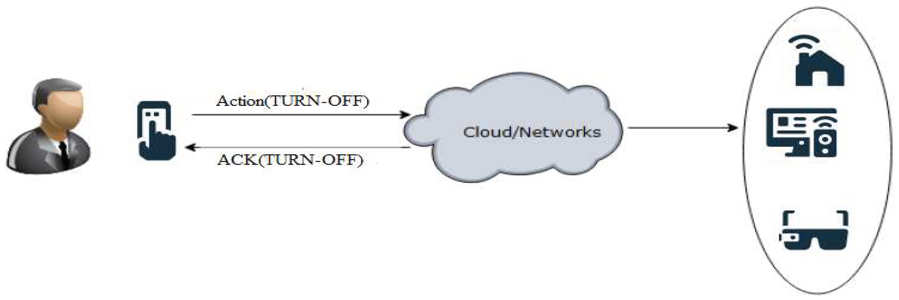
It is important to note that the data might be altered in such a cloud constraints enjoinment. IoT, therefore, rises concern about traceability. To understand this problem we discuss a case (see Figure 1.2, Figure 1.3), where Abid and Amir are two brothers live in a smart house with their family (equipped with IoT devices).

Table 1.
IoT issues and Blockchain features to solve them.
 |
and due to the diversified connection between services and smart IoT components, the data is more prone to attack by gain unauthorized access and may misuse the nodes of IoT network [2] [5] [10]. Therefore in the field of IoT requirements for privacy and data protection are increases. This puts onward a research question in the Internet of Things field.
Additionally, with the introduction of cloud traceability of source becomes a major problem. For example a user requests acting directly to the source. Because of direct connection traceability becomes easy.
One day Abid leave the house for work and turned off his Smart AC. But his brother Amir, who also leave home for university turned the smart Ac on and then forgot to turn it off. At 6 pm Abid comes back from office and he noticed that his IoT equipped smart AC is on. Abid will be disappointed and wanted to know which one of the house members turned it on at whatever time he is in his office. If Amir interconnected to AC using a direct link as shown in Figure 1.2, it is easily traceable. However, such as described in Figure 1.3. The connection between Amir and AC is not direct. It becomes hard to trace due to a lot of resources in the cloud constraint environment. Therefore it becomes very hard to know which one is behind the services of the cloud.
Figure 1.
1. Data violation in the IoT environment.
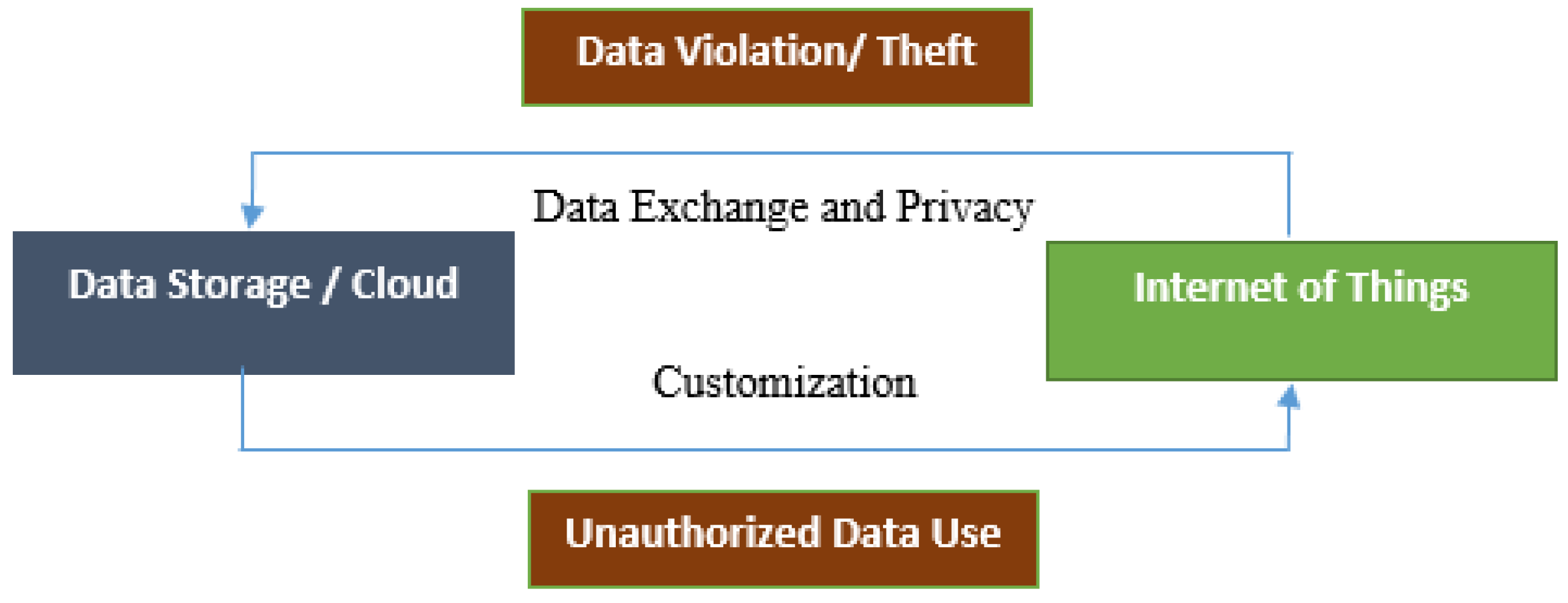
Figure 1.
2. The direct connection between User and IoT Devices.
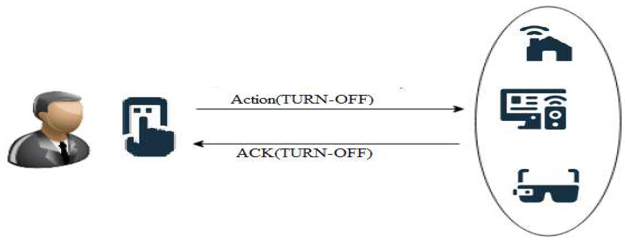
Figure 1.
3. Indirect Connection through cloud between User and IoT devices.
B. Protocol Use For IoT Communication
Interconnection between IoT instruments is required to communicate with each other for the exchange of data and then sends it to the storage medium for further processing. However, for communication, these components required to have a shared language that is called the protocol. Conversely, there are many IoT protocols, the two most used are the Message Queue Telemetry (MQTT) and Constrained Application Protocol (CoAP).
- 1)
- Message Queue Telemetry (MQTT)
This protocol is developed by IBM [20] and aims to interconnect small components to a limited resources network. It uses a transmission control protocol (TCP). Furthermore, for the distribution of messages, it uses 3 steps. That is as fellows. At-most-once: Messages are delivered at most once. This specifies that message delivery is not recognized. At-least-once: it ensures that a message must be delivered at least once. Conversely, the message can likely be sanded many times. Exactly-once: It takes a long time for message delivery and for receiving confirmation between the sender and the receiver. This makes sure that message gets only once.
- 2)
- Constrained Application Protocol
CoAP was developed in June 2014, at the University of Bremen to allow communication between IoT components with limited resources concerning processing and bandwidth. CoAP is a Representational State Transfer protocol (RESTful), it was developed by the Internet Engineering Task Force (IEFT) and runs on UDP (User Data Protocol) and also uses HTTP (Hypertext Transfer Protocol). Furthermore, CoAP has a big packet size range from 4 to 1024 bytes [21] [22].CoAP has four categories of messages as described below. Non-Verifiable-message: acknowledgment is not delivered for this type. Verifiable-message: acknowledgment is delivered for this type. A user continuously sent a connection request message till an acknowledgment is received with the same message-ID. Reset-message: This massage is used for confirmation of a Non-verifiable message it receives. Acknowledgement-message: it identifies that a message used to confirm a confirmation message has been received.
- 3)
- REST
In 2000 Roy fielding Representational State Transfer (REST) [23]. REST, a considerable structure highlights the important standards behind the modern Web-software designs. The web grants an un-securely combined application architecture, where resources are most important to the design of architecture. The resources are accessed in using methods like PUT, POST, GET, and DELETE [23].
II. RELATED WORKS
Recently, a lot of scholars have directed research on traceability, data privacy, and accountability of the resourceful network of IoT. To familiarize the changing behavior of the IoT network environment, recognize well-organized public key sharing supervision as well as consistency assessment and escape the participant nodes in the network, belief the bogus keys available publically which assure the privacy as well as the efficiency of data communication.
Different researchers [13] [6] [7,8]have designed techniques for data privacy in IoT for different reasons. For example, crowd-sensing in mobile authors [6] describes a Dynamic Trust Relationships Aware Data Privacy Protection (DTRPP) tool. It essential needed that each node directs the dynamic evaluations to both facing nodes and public-keys they deliver. The data is characterized as well as sanded based on varied privacy requirements.
To discover and prevent attacks in communication network author in [7] designed a method. However, to discover new attacks this methodology is incompetent (e.g. zero-day exploits attacks). It is unrealistic to remove all security threats in a network and there is no guaranteed solution. Priority-based on their location in the attack graph to gain information about network nodes, Abazari, and Madani in [9] suggested a weighted attack graph-based model that calculates threats. Explicitly, this is designed to reduce threats and costs. A dynamic proactive multi-purpose threat reaction model.
Kalnoor and J. Agarkhed [8] for wireless sensor networks proposed an intrusion detection system (IDS) using a pattern comparison technique. When the pattern matches an event, pattern comparison describes undesirable events based on pattern comparison defines a set of signatures and, a specific action is executed defined by a set of signatures or rules. Then, the IDS examines the calm data and compares these data with a bulky signature set. An alert is produced based on a continuous mismatch between current and previous patterns.
Ali Dorri et al [15] proposed protected BC-based architecture for the smart vehicle ecosystem a decentralized privacy-preserving method. Service providers such as smart vehicles, original equipment manufacturers (OEMs, i.e., car manufacturers), mutually form an overlay network where they can interconnect with each other. Design based on LSB (Lightweight Scalable Blockchain) due to its low expenses. Nodes are clustered in the overlay, and only the cluster heads (CHs) are responsible for the management of BC and performing its central roles.
Therefore these nodes are known as overlay block managers (OBM). Transactions are broadcast to and confirmed by the OBM, thus removing the necessity for a central broker. To protect user privacy, each vehicle contains in-vehicle storage to kept privacy-sensitive data (e.g., location traces). Which data is providing to third parties in exchange for advantageous services and which data should be only stored in the in-vehicle storage is defines by the vehicle owner (and the granularity).
Subsequently, in the communication process the originator has more right to deal with the data. While collaborating with the overlay vehicles can be mobile. Latency is increased when a vehicle is physically distant from its related OBM.
Mandrita Banerjee and Kim-Kwang Raymond Choo [12] proposed an approach, in which references of member repositories maintain by a central hub where the datasets are stored and distributed. Blockchain retained the membership information such as an address, owner, and sharing policy. In other words, membership information is kept and public by all members as well as the hub. There is another chain of blocks that keeps RIM (to ensure the integrity of the datasets, a reference integrity metric (RIM) of datasets.
The privacy of datasets is a major concern when datasets are openly accessible. To escape the harm of any data privacy rule and protect privacy, the author highlights the need for an automatic tool that anonymous datasets earlier to the announcement of these datasets. The lifetime of datasets is another challenge we need to study. The owner of the underlying datasets may not want to share the dataset forever.
However, in blockchain when any transaction is recorded, it cannot be altered or removed. While this is a resilient security attribute, it may not be helpful in distribution if any record needs to be removed. The only RIM is maintained by the blockchain in the proposed dataset framework. Therefore, datasets will not be available for a long period of sharing even if the RIM remains in the blockchain.
III. ALL RELATED STUDIES EXPOSE THAT NOTHING HAS BEEN DONE FOR THE TRACEABILITY, DATA PRIVACY, AND ACCOUNTABILITY IN THE IOT NETWORK. ON THESE BASES, THIS PAPER AIMS TO DESIGN A TDA BASED BLOCKCHAIN ARCHITECTURE THAT PROVIDES TRACEABILITY AND DATA PRIVACY FROM UNAUTHORIZED PERSONAL IN THE IOT NETWORK.PROPOSED ARCHITECTURE
Figure 2.
Proposed TDA Architecture.
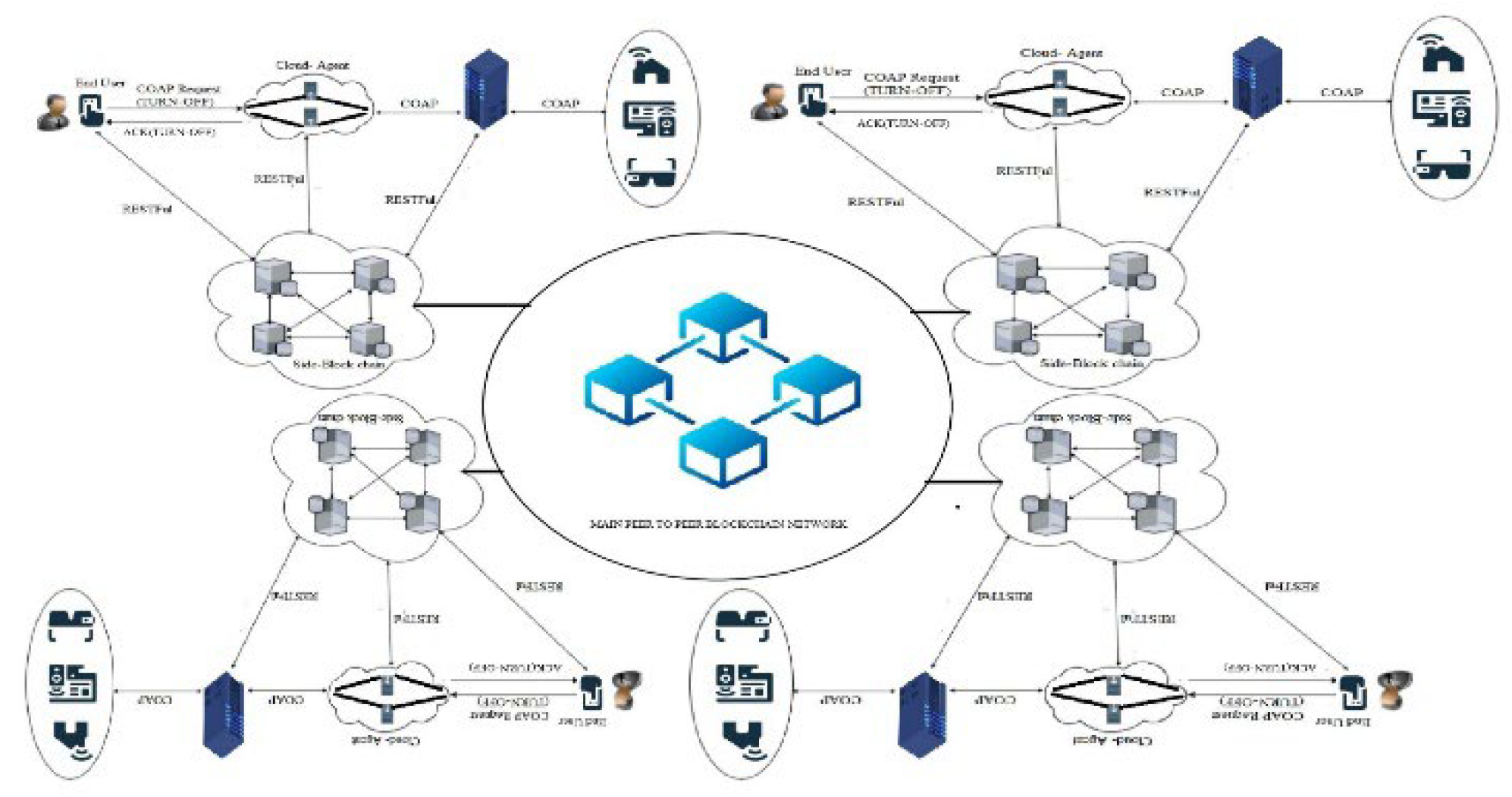
A. Data Privacy in the Proposed System
AS in Figure 2 for providing TDA in IoT a network architecture of IoT is designed we call them ‘TDA’ architecture. To covers the privacy of data as describes in Figure 3, the main blockchain is breaking down into side-blockchains (SBC). These SBC IoT networks are interlinked to create a single peer-to-peer IoT network. The major benefit of using SBCs is that the nodes of one SBCs don’t have the right to participates in the validation-process of transactions in other SBC. Users manage these SBC According to needs. Every SBC has different use cases of the network and may be added or deleted from the main blockchain. For access information of an SBC IoT network the end devices first need to recognized through and also becomes the part of that SBC IoT network. SBC helps for access control and providing authorized access. If only one blockchain were to use all IoT records might be the privacy of data compromised because the records are accessible to all the users. But, in proposed architectural design, any entity of the network will only be capable to access IoT data after successful request access.
For example an SBC network of cameras collects video data from the environment and added it to a new block of this SBC. Finally its hash is stored in the smart contract of the main blockchain. Another SBC network of sensors observes the environment, the same as the SBC network camera added to the new block and hash stored in the smart contract. If the sensor network of SBC wants to access data of SBC cameras network then this must require to take permission from the validator node of this network. Finally after the permission of the validator node it can be able to see the content of the camera's network.
Figure 3.
Blockchain IoT Data Privacy [1].
Figure 3.
Blockchain IoT Data Privacy [1].
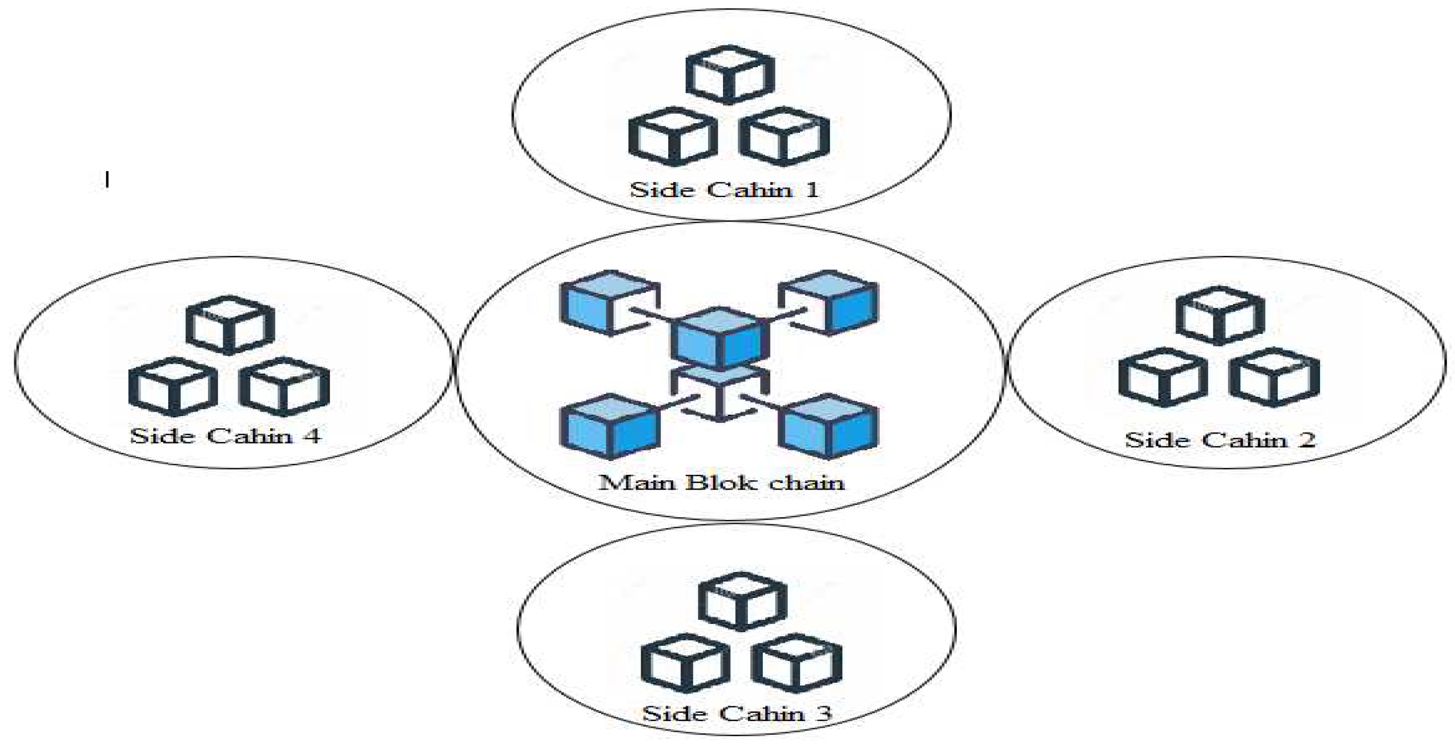
Figure 4.
IoT Data Access Process.
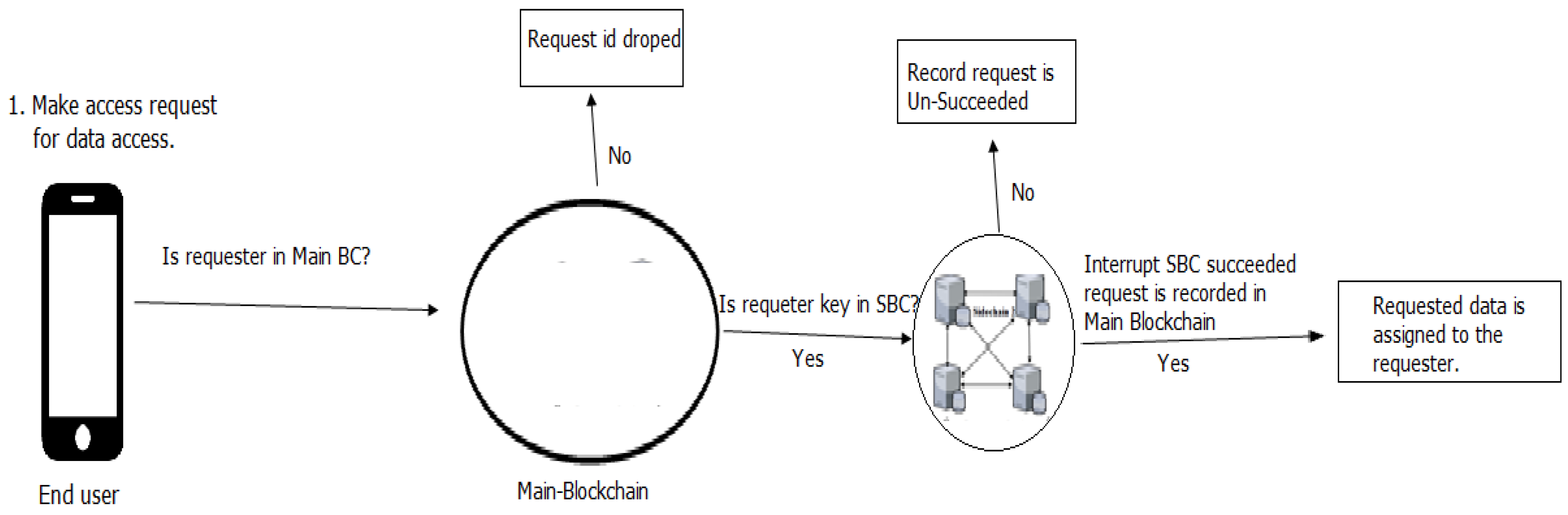
As in Figure 4 for accessing data/ information from SBC, a request initiator essentially requires to become a member of the central blockchain network, by an application as a member peer. Additionally to share IoT data, the SBC proprietor adds the public key of request initiator to the SBC smart-contract, along the time required for access rights allocated to the request initiator.
Exactly at this time, the validation-node also added public-key to blockchain in the authentic participant's list. For getting access to the data of IoT, the requested transaction is digitally signed by the initiator with the private key. Figure 3 Indicate a flowchart for IoT data access. The ability to change the accessing rules mark the end-user capable to select, to with he desires to share their data of IoT. When a requester request range exceeds the total number of un-succeeded request, the smart-contract remove the relevant key from the record of authentic requesters.
B. Traceability in the proposed system
As in Figure 5 main characters of proposed TDA architecture are the End-user (request initiator), an agent in the cloud, and the server (that deliver services). The end-user connects to the blockchain database and then records its resource information such as a uniform resource identifier (URI), URI of Server or services provider, and also time-stamp. For providing traceability this paper focuses to record the lifecycle of request/response in IoT components intercommunication.
Additionally, the end-user initiates a CoAP request and added its URI to this requested payload. If effectively sent the request, then the request is taken by the cloud-Agent and distributed database recorded the information. The cloud-Agent creates a new chain for requesting the blockchain and then records the request information contains (To, From, Timestamp, resource, and method) database of blockchain.
For checking the originality of the message, the cloud-agent uses a randomly generated message ID that necessarily compared the original message send by the end-user. The clod-Agent then added its URI information to the message it gets from the end-user and then sent this message to the services provider.
It is important to note that there is a possibility for request message which is sent by the end-user will direct through different tracks reflect the number of cloud-agents in the partial resource environment. When a request message is received, the server then connects and takes the information of the message which is (To, From, Time-stamp, resource, and method) in the database of blockchain.
Figure 5.
Traceability in Proposed TDA Architecture.
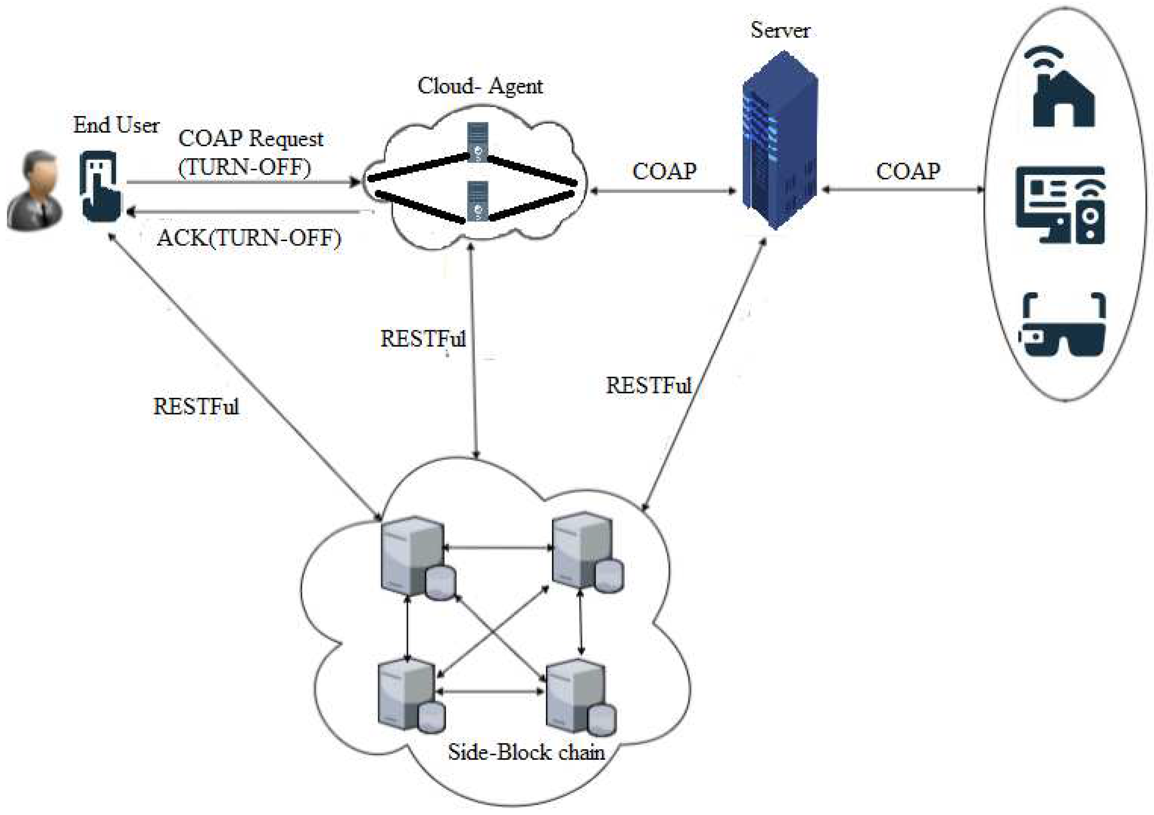
Furthermore the server makes a new message, and also ensures the uniqueness of the message receives from cloud-Agent. The server uses a randomly generated message ID that is sent by the cloud-Agent to make sure the uniqueness. This is finished as the request message goes via different components of IoT must be desired to have the same ID of the message as the source has.
Additionally, the server creates a different chain entitled as a response chain measured in the blockchain. The services provider or server normally takes the record as source information which is (To, From, Timestamp, resource, and method). Moreover, the server adds its URI to the reply message and then forwards the response data along with the reply message status to the cloud-agent. As defined earlier, in the cloud there is a possibility that the response message sent by the server might be distributed through different paths and not delivered through the same way it arrives.
Therefore, any cloud-agent in the cloud might be capable of intercepts the response message and then sent the request message. Once that the cloud-agent receives the response message, and then creates the message for a response that has information (To, From, Timestamp, resource, and method) insides the response chain and then recorded its source into the blockchain. And use a randomly generated message ID to match the original message ID.
Also, the cloud agent added its URI to the responded message comes from the server. The cloud-agent also provided the response data to the end-user alongside the status. The end-user receives the message from the cloud-agent with the response status. After receiving, the end-user creates response information within the response chain in blockchain, which has the source information (To, From, Timestamp, resource, and method). Furthermore, to makes sure that message ID is the same as original, a randomly generated message ID is compared response message.
The end-user also identifies that it has obtained the message, via added its URI to the message that comes from the cloud-agent. All source information is captured and recorded in the blockchain.
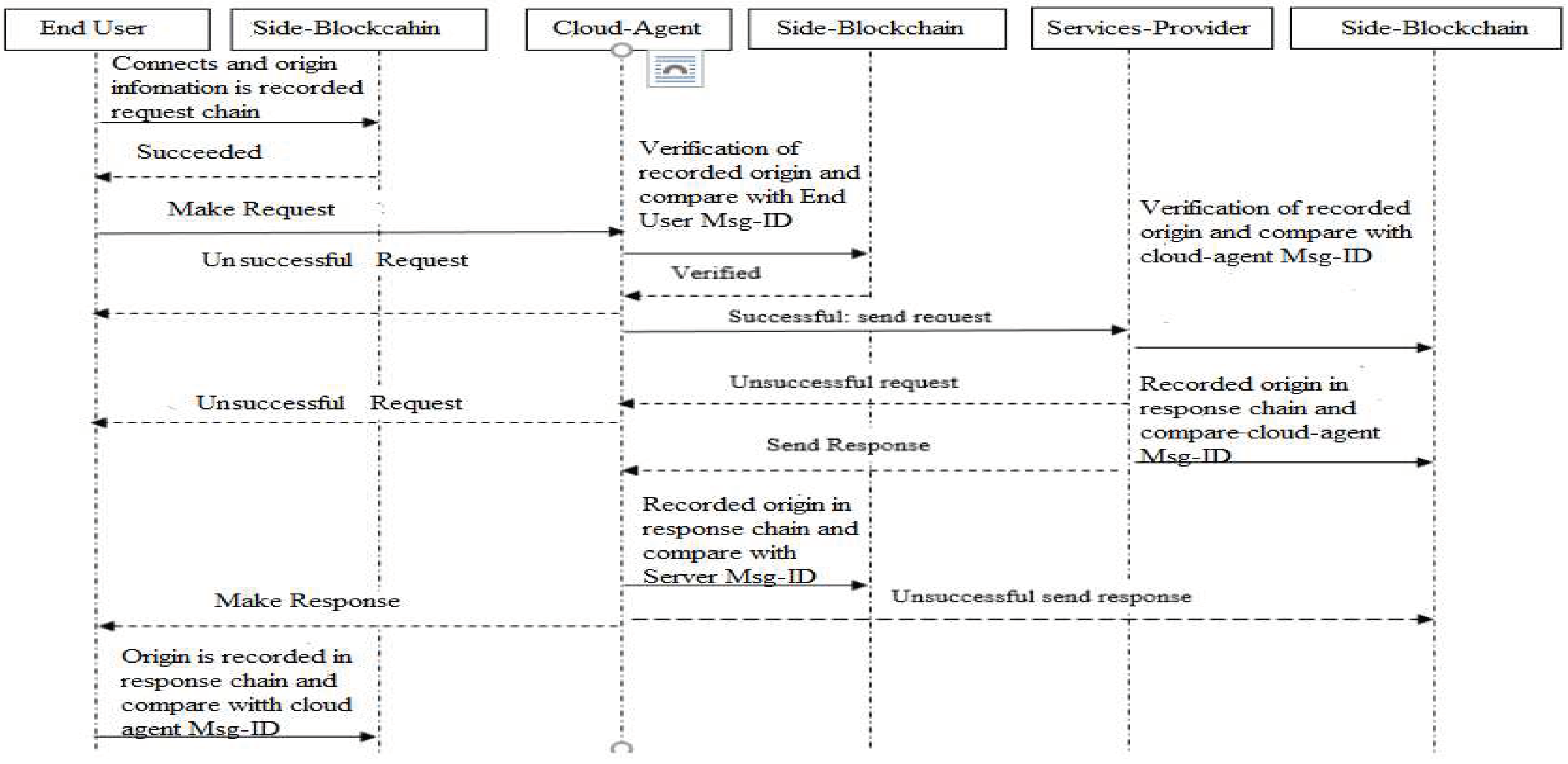
Due to the immutability nature of source blockchain, it makes this as respectable technology best for tracking of source or traceability. This is due to it is an append-only database, which means that when source information is stored it is difficult to change this as all activities focused from beginning to the end are recorded. As a result of source tracking between the modules become transparent and accountable as in Figure 6.
C. Accountability of Making Requests
Each member of the network is allowed to see the unchangeable record of all requests of access delivers accountability for all requests. Assume the scenario where a member trades his data to an organization. The member approved the organization's access for 5 days. If the owner cancels the rights of access earlier than the expiry date, the organization access is denied. The organization may yield the time-stamped record of its un-succeeded access.
Programmability to the blockchain conveyed by Smart Contracts, helps in the carrying out of transactions however by fulfilling the conditions of contract code. A specific address is used to deploy smart contracts in the blockchain, so for performing the action written or programmed in a smart contract, the transaction is signed digitally by nodes and addressed themselves to the smart contracts. However conditions enforced by smart contracts for transaction and access control policies in the proposed TDA architecture.
Figure 6.
Sequence diagram complete communication among the roles as adapted from [14].
Figure 6.
Sequence diagram complete communication among the roles as adapted from [14].
IV. IMPLEMENTATION AND RESULTS
Multichain and Golang are used to implement the proposed architecture. It allows software developers/ Engineers to develop user-friendly and effective software. For the implementation of the proposed architecture, the third-party library of Golang is used that delivers both CoAP and server-side Implementation support that is designed by Dustin Sallings.
The implementation code is divided into the following four parts.
- 1)
- End-User Side
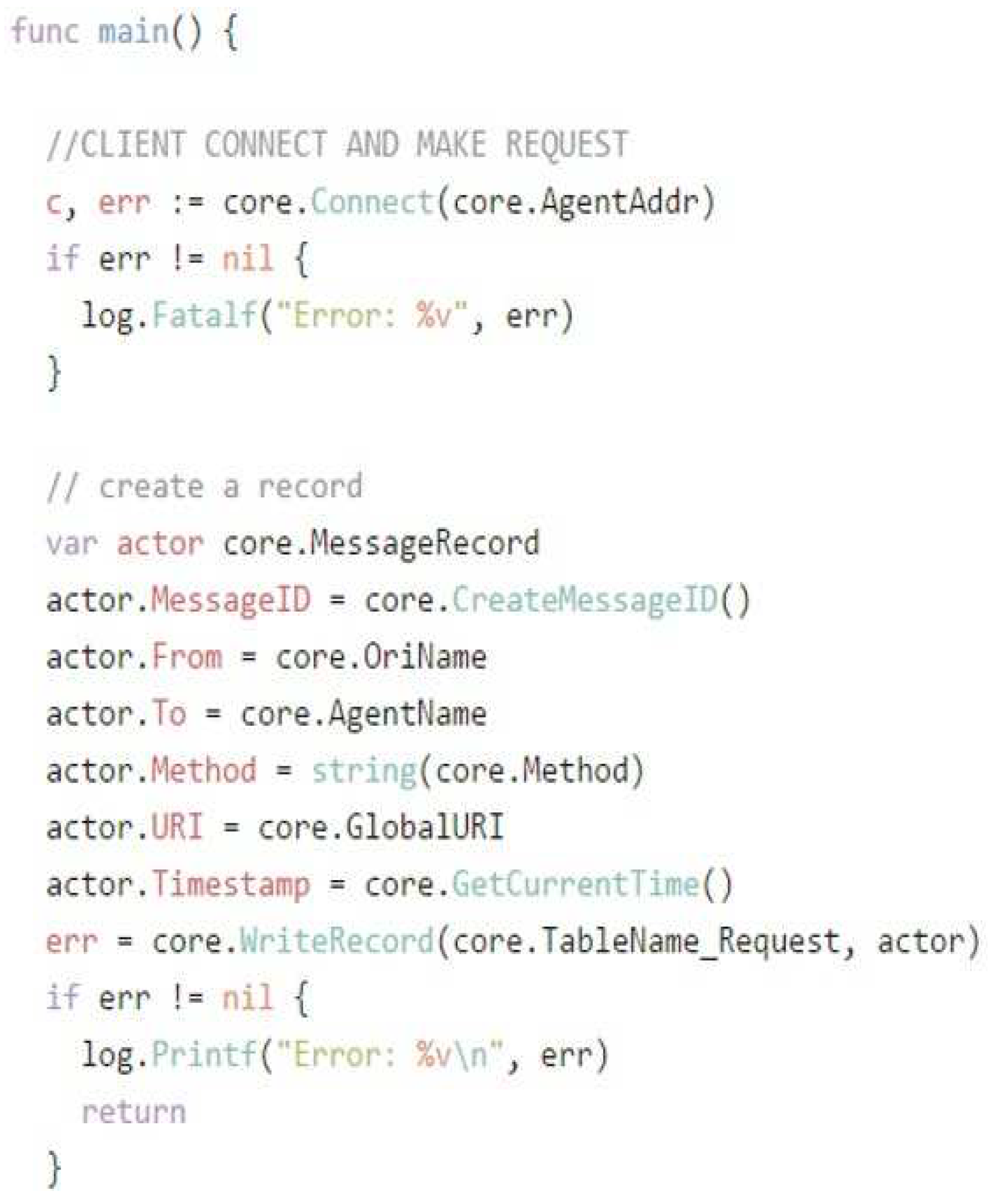
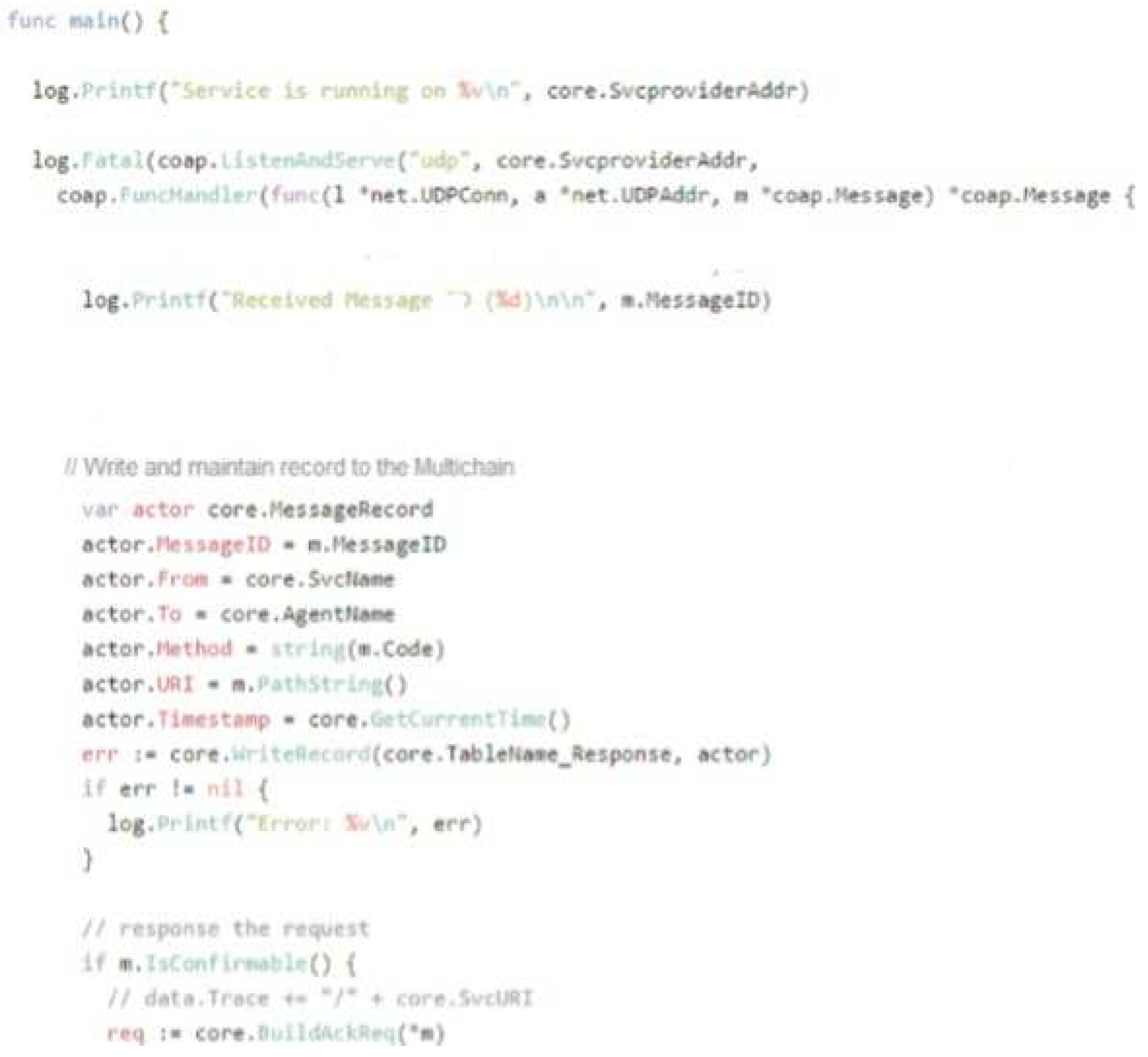
As described in Figure 7, End-User coding is written in Golang and permits the End User to link to the decentralized blockchain, which is the distributed database of multichain. After interconnection a function WriteRecord records the End User: Message-ID, To, From, Process, URI, and Time-stamp.Then attached the above information and forwarded the request consisting of the message data that is used to describe End User URI (uniform resource identifier) to Cloud-Agent.
Figure 7.
End-user side code.
- 2)
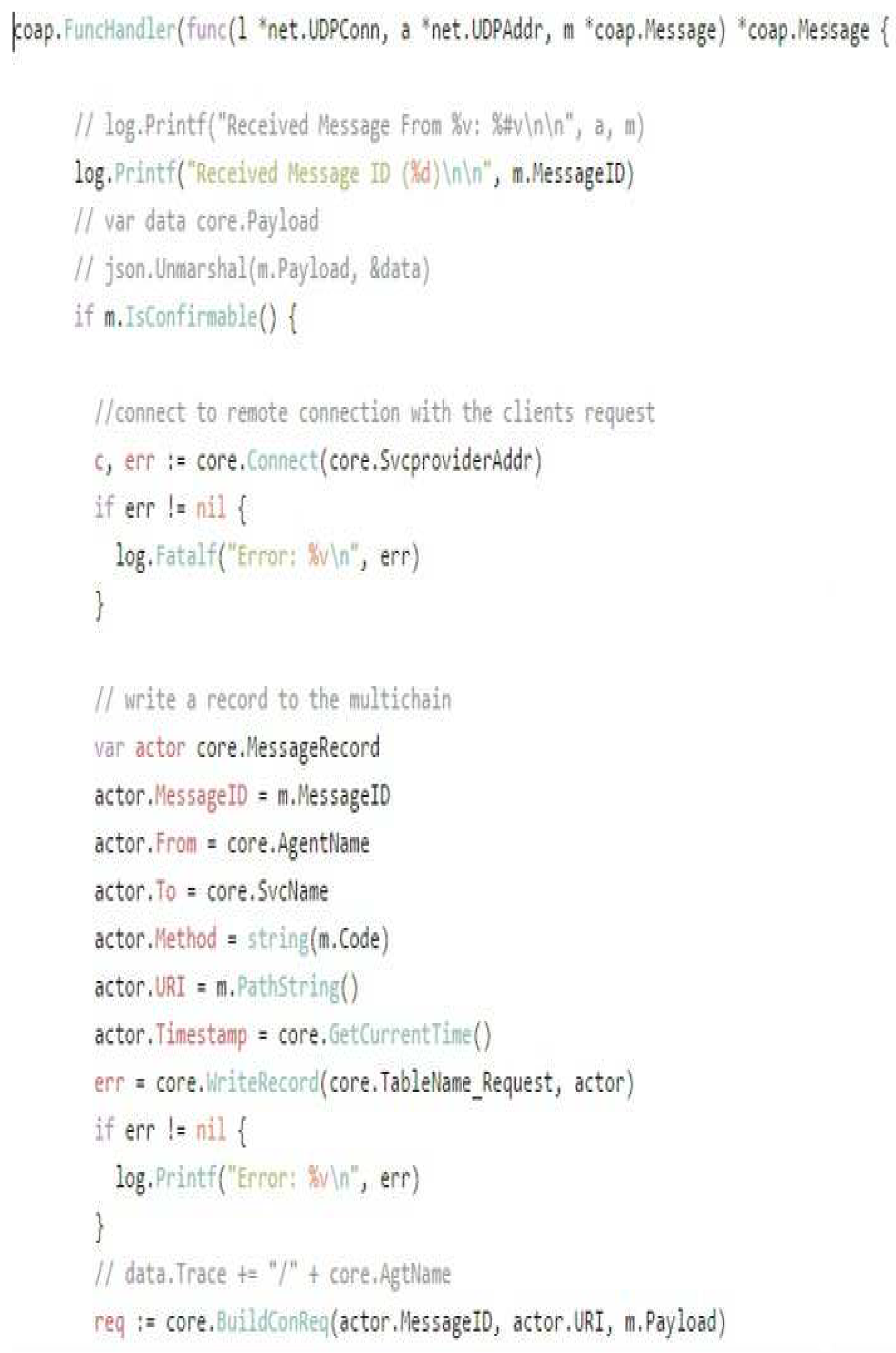
- Cloud-Agent Side
Cloud-agent side coding is also written in a language known as Golang as in Figure 8. The cloud-agent side coding connects the cloud-agent to multichain and writes source information to multichain using WriteRecord function. After receiving a request message from a user and clod-agent then accepts plus recognize the message. Finally deliver it to the server.
Figure 8.
Cloud-Agent side code.
- 3)
- Server-side coding
The server provider coding is also written in Golang likewise discussed in Figure 9. After listening and recognizing the request and server interlinks to then perform the using WriteRecord function, records its source information like Message-ID, To, From, Process, URI, and Time-stamp. The URI of services provider or server also added for identification of message. A similar method is repeated with the cloud-agent and the end-user, meanwhile, the coding implementation is done efficiently to make sure the traceability in bidirectional communication from the end-user to the cloud-agent and from the cloud-agent to the services provider or server.
Figure 9.
Server-side code Environmental Setup.
Implementation set-up is comprised of hardware and software components. The hardware components mandatory for this practical implementation consist of Install Move Add Change (IMAC), workstation, and raspberry pie-2. The IMAC is used for simulation of End User IoT components. The workstation is for cloud-agent and the raspberry of type pie-2 server for simulation of the server. A list of components is the following.
- ✓
- Local Environment Components
IMAC – End-User Device
1. Brand =IMAC
2. OS = Mac OS X 10.10Yosemite
3. CPU =Intel Core i5 CPU 3.0 GHz
4. Memory =16GB
- ✓
- Raspberry1pi-2:Cloud-Agent
1. Brand =Raspberry-Pi-2
2. Model=B
3. OS=Raspbian
4. CPU=800 MHz plus 3.0 GHz
5. Memory - 2GB
- ✓
- The workstation of Lenovo for server
1. Brand=M series2. OS=Windows 10
3. CPU=Intel Core i7 3.40 GHz
4. Memory=16GB
- ✓
- Workstation for Blockchain Nodes
1. OS=Ubuntu 16.04 Long Term Support (LTS)
2. CPU=Intel Core i7 3.40GHz
3. Memory=8 GB RAM
- ✓
- Cloud
1. OS: Ubuntu 16.04 Long Term Support (LTS) for every node
2. CPU=Intel Xeon 2.40GHz
3. Instance of type=t2.medium
4. Availability zone=us-east-b
5. Memory=8GB RAM
Figure 10.
The physical structure in Cloud.
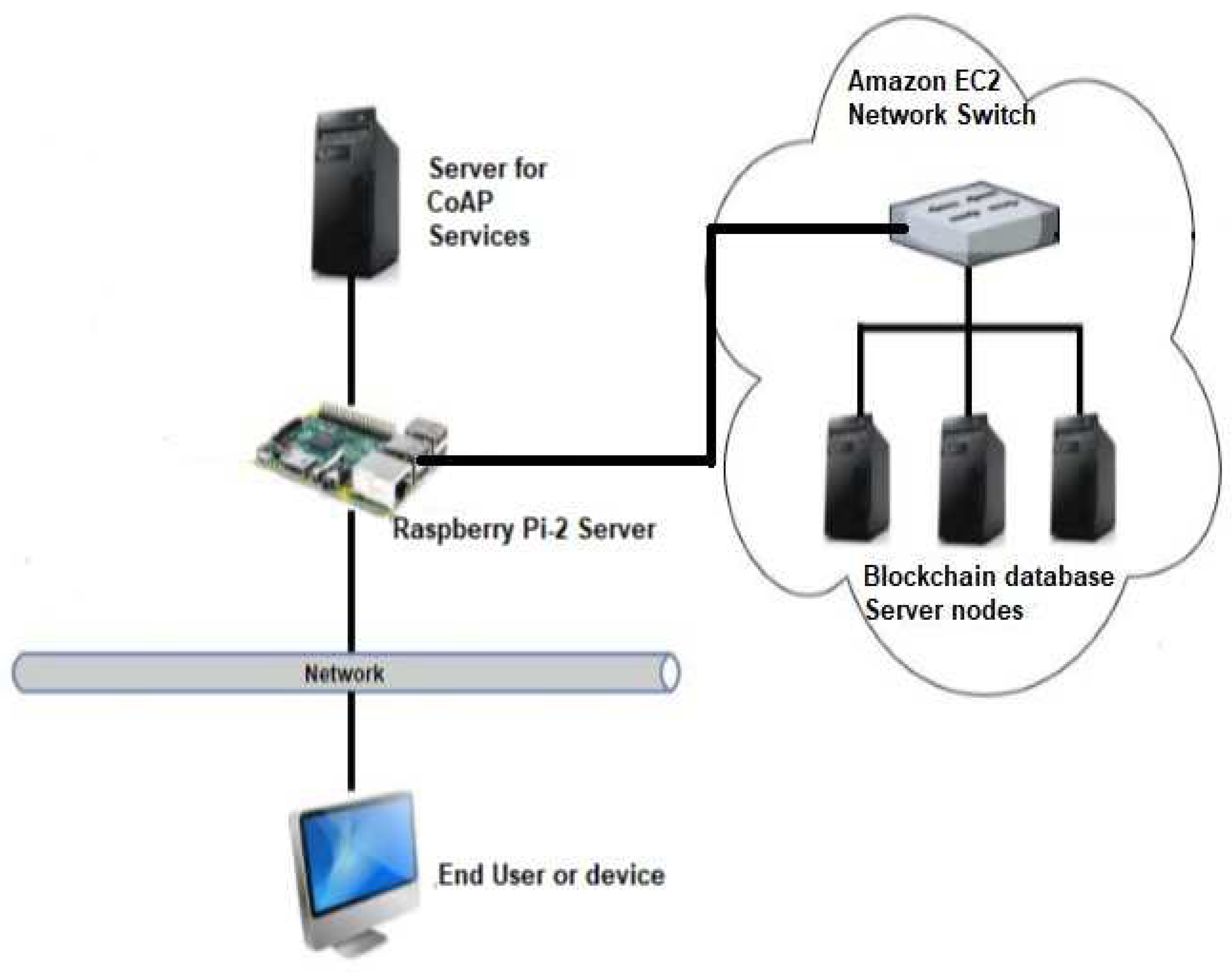
B. Physical Structure
The structure is ordered in the local and cloud environment (Figure 10). Ethernet technology enables local communication among the IoT components. All devices of the network (server, raspberry pie-2, blockchain database (Multi-Chain, and the end-user) are interconnected to a switch using Ethernet technology.
Each code is evaluated on the particular machine before the actual experimentation. Based on the action each code performs in the system, each code of implementation accomplishes different functions. As, the blockchain technology distributed database is used, this needs 3 end nodes for analysis throughout the experimental environment.
C. Data collection
For assessment we use Apache J-Meter on the end device, an open-source assessment software that supports different performance assessment metrics. A library that is designed by Dustin Sallings is used for Apache Jmeter to support the CoAP protocol. Additionally, a data-set of different size consists of 4, 8, 16, 32, 64, 128, 256, 512 bytes is chosen for performance assessment. For scalability 1, 20, 40, 80 and160 users were selected to make sure that the system can support many users.
D. Performance Metrics
Response-Time: time occupied by an End device to make CoAP request that is passed from agent as final to the server and write the record to database.it is dignified in milliseconds (ms). Through-put: the total amount of data sanded through the network per second. It is measured in transaction per-second.
Pay-load1size: the total amount of data sanded alongside the CoAP request through the network that is measured in bytes.
Users Quantity: total users that request a system at the same time. That is used for the assessment of scalability.
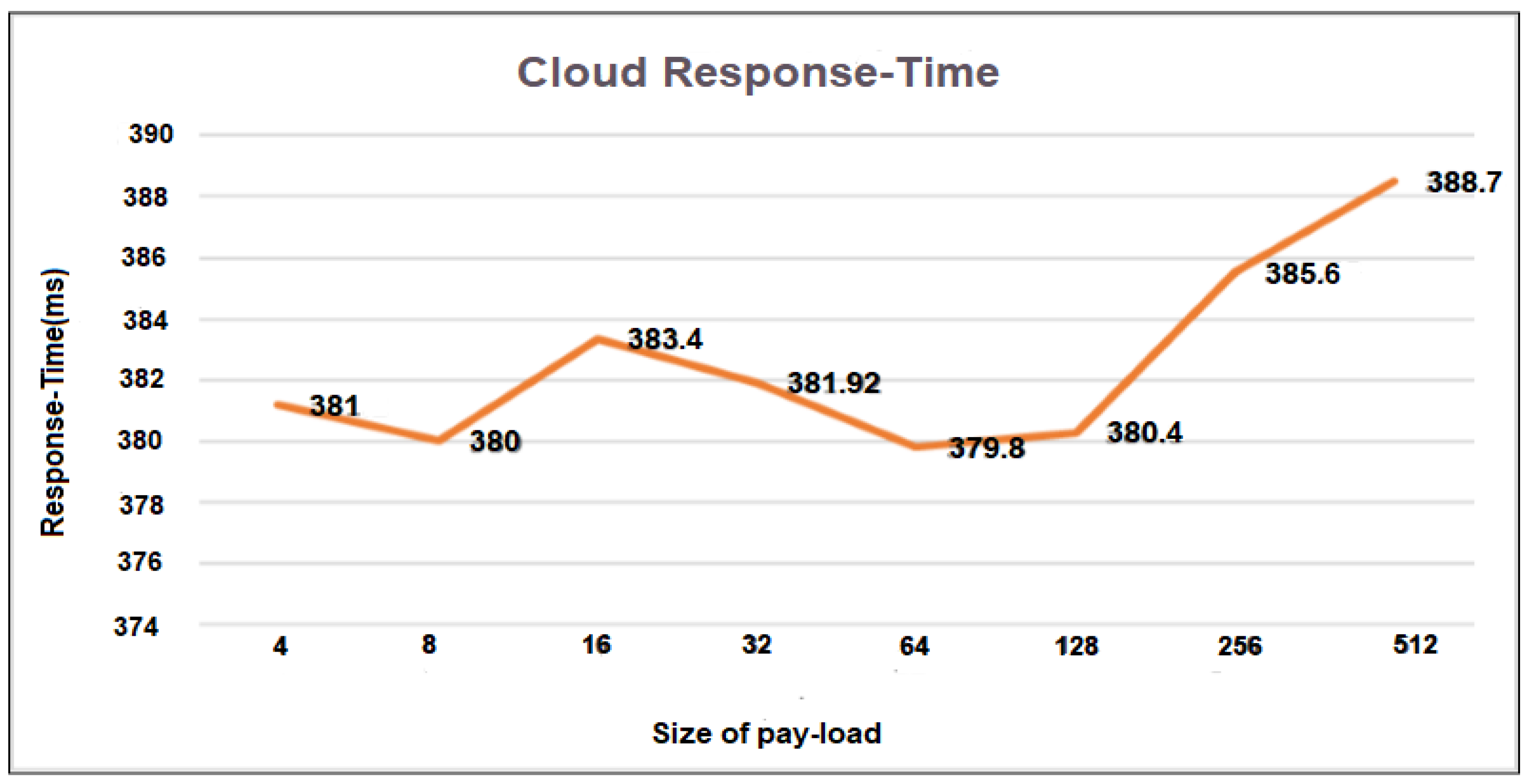
Figure 11.
Single user based Response time and Pay-load in Cloud.
E. Performance Evaluation
As described in Figure11 pay-load sizes encompassing 4, 8, 16, 32, 64, 128, 256, and 512 is collected with the corresponding response-time. From the result we observed that pay-load from 4 to 128 byte occupied the time for response between 380 to 384 ms. But, the response time for 256 and 512 should be increased.
In Figure12, the number of users who makes requests 1, 20, 40, 80, and 160 are displayed on the x-axis while the response time on the y-axis. From the result we observe that when the number of users who requests at the same time increased, response-time for more than 40 user’s cases is increased. Moreover it is also observed when the payload size increases, the response time is also increased.
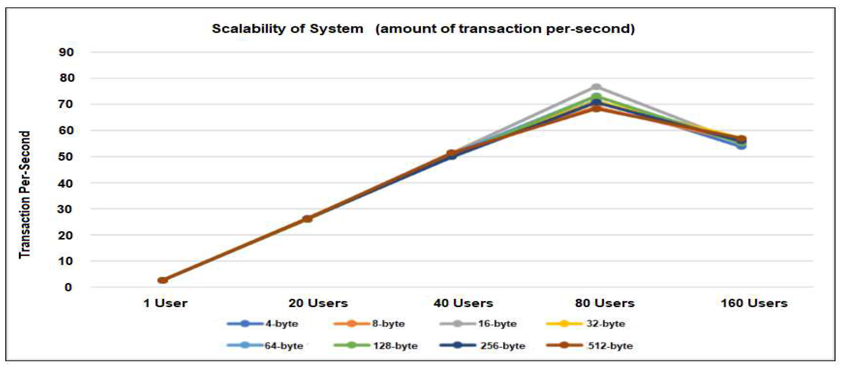
As described in Figure 13, the number of users who makes requests 1, 20, 40, 80, and 160 are displayed on the x-axis and through-put (total amount of transaction/ per-second) on the y-axis. From results we perceived that increment in response time decreases the number of transactions per second (throughput). Also when the amount of user’s extents 160 as described in Figure9, throughput is decreased.
Figure 12.
Multi-user based Response time and Pay-load in Cloud.
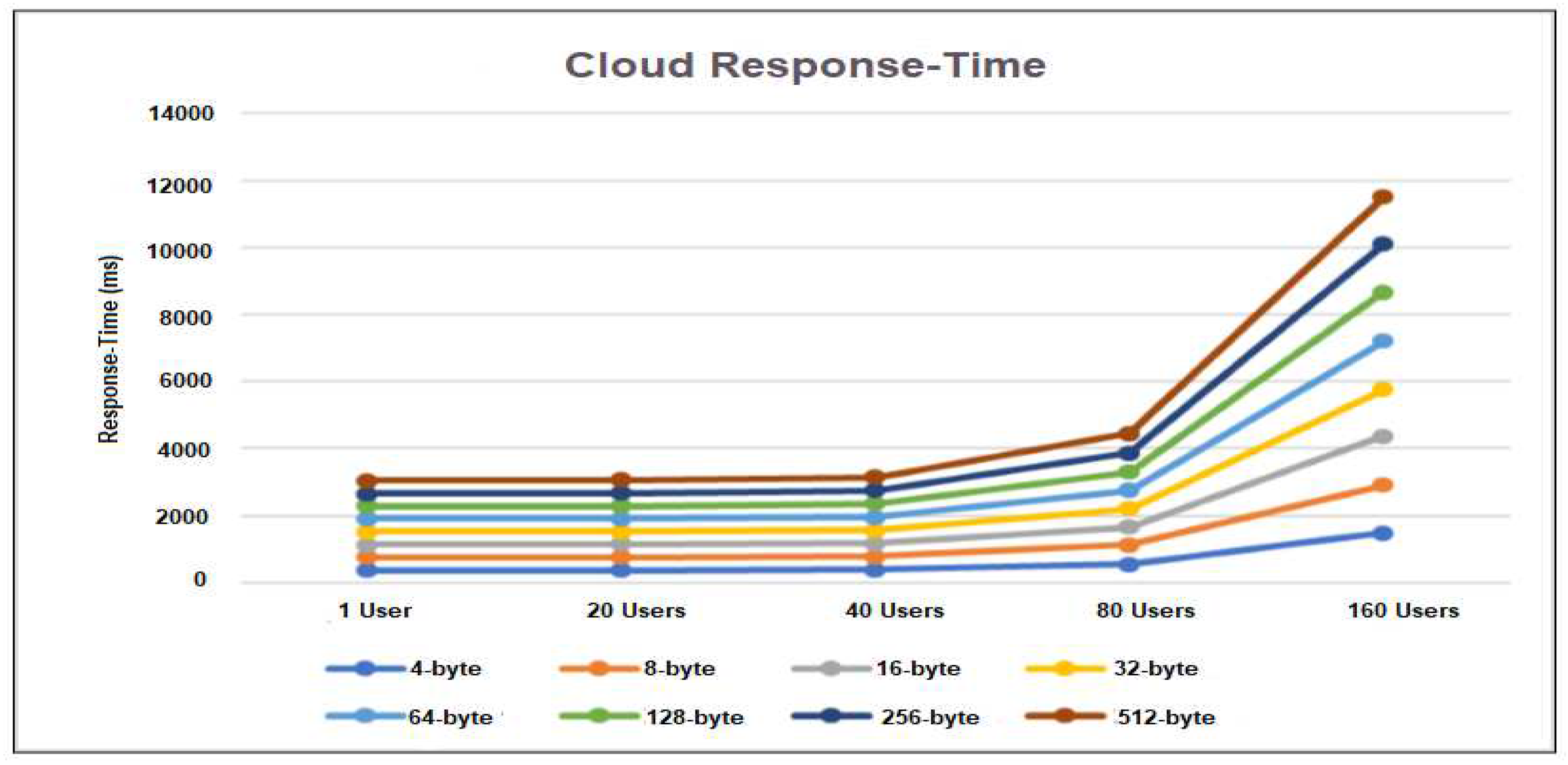
Figure 13.
Scalability of SystemConclusion And Future Works.
IoT connects things or instruments with the Internet to collect and process data to support for delivering new services for creating an intelligent society. In the last few years IoT has become popular because of its utilization in smart homes and cities throughout the world. Inappropriately, IoT instruments consume low computation power, storage, and network capacity. So, they most likely to attack, as compared to other devices such as mobile phones, or PCs. The more usage of IoT devices or things connecting to the network and data collection from smart instruments generate an issue with regards to traceability and data privacy insides the IoT network. Blockchain, is a decentralized not changeable database that is documented to supports and appropriate for TDA because of its features. Blockchain provides the main feature of the append-only database, which means, the records cannot be changed and retains the history of records in order from start to end. The purpose of this paper, is to suggest and design an architecture that makes uses of blockchain to support TDA in IoT.
Future Works
In this paper blockchain is used for supporting TDA. Also, many features of the proposed system design have been discussed. However, the system still requires some improvement and currently proposed system based on a single User. For future works we confident for the addition of more end-users to conclude and estimate the evolution of proposed deign as we increase the number of End Users.).
References
- Abid sultan et al,” IoT Security Issues Via Blockchain: A Review Paper”, ICBCT 2019, March 15–18, 2019, Honolulu, HI, USA © 2019 Association for Computing Machinery. ACM ISBN 978-1-4503-6268-9/19/03…$15. [CrossRef]
- Sultan A (2018) Internet of Things Security Issues and Their Solutions With Blockchain Technology Characteristics: A Systematic Literature Review. Am J Compt Sci Inform Technol Vol.6 No.3:27.
- Franklin Okeke, “The top 5 industrial IoT use cases:https://www.techrepublic.com/article/industrial-iot-use-cases/in Internet of Things on November 8, 2022.
- F. Hussain, R. Hussain, S. A. Hassan and E. Hossain, (8, April 2020)"Machine Learning in IoT Security: Current Solutions and Future Challenges," in IEEE Communications Surveys & Tutorials. [CrossRef]
- M.A. Khan, K. Salah, “IoT security: Review, blockchain solutions, and open challenges”, Future Generation Computersystems(2017). [CrossRef]
- Dapeng Wu, Shushan Si, Shaoen Wu, Senior Member, IEEE, and Ruyan Wang” Dynamic Trust Relationships Aware Data Privacy Protection in Mobile Crowd-Sensing”, IEEE Internet of Things Journal, I OT.2017.
- M. Yevdokymenko, "An adaptive algorithm for detecting and preventing attacks in telecommunication networks," 2016 Third International Scientific-Practical Conference Problems of Info communications Science and Technology (PIC S&T), Kharkiv, 2016, pp. 175-177.
- G. Kalnoor and J. Agarkhed, "Pattern matching intrusion detection technique for Wireless Sensor Networks," 2016 2nd International Conference on Advances in Electrical, Electronics, Information, Communication kand Bio-Informatics (AEEICB), Chennai, 2016, pp. 724-728.
- F. Abazari, A. Madani and H. Gharaee (2016), "Optimal response to computer network threats," 2016 8th International Symposium on Telecommunications (IST), Tehran, pp. 729-734.
- M.S. Ali, K. Dolui and F. Antonelli (2017), “IoT data privacy via blockchains and IPFS”, International Conference on the Internet of Things (ACM, New York).
- NEST, “Nest Thermostat,”. [Online]. Available: https://nest.com/uk/thermostat/meet-nest-thermostat/. [Accessed: 18-Apr-2017].
- F. Wang et al (2015), “A survey from the perspective of evolutionary process in the internet of things,” Int. J. Distrib. Sens. Networks, vol. 2015.
- M. Banerjee, J. Lee, K.-K.R. Choo,“A blockchain future to Internet of Things security: A position paper”, Digital Communications and Networks (2017). [CrossRef]
- E. Kaku, R. K. Lomotey, and R. Deters, “Using Provenance and CoAP to track Requests/Responses in IoT,” in Procedia Computer Science, 2016, vol. 94.
- Ali Dorri et al (December 2017), “BlockChain: A Distributed Solution to Automotive Security and Privacy”, IEEE Communications Magazine.
- K. Rose, S. Eldridge, and C. Lyman (October 2015), “the internet of things: an overview”.
- W. Stewart (2000), “the Internet Toaster.’ Living Internet,” web. [Online]. Available: http://www.livinginternet.com/i/ia_myths_toast.html.
- Gartner (20-oct-2021) “Reveals Top Predictions for IT Organizations and Users and Beyond,” Gartner.
- IDC FutureScape: Worldwide Internet of Things 2017 Predictions.
- D. Locke, “MQ telemetry transport (mqtt) v3. 1 protocol specification, IBM developerWorks Technical Library,” Ibm, 2010.
- S. Xue, R. K. Lomotey, and R. Deters, “Enabling Sensor Data Exchanges in Unstable Mobile Architectures,” Proc. - 2015 IEEE 3rd Int. Conf. Mob. Serv. MS 2015, pp. 391–398, 2015.
- Z. Shelby, K. Hartke, and C. Bormann, “The Constrained Application Protocol (CoAP),” Rfc 7252, p. 112, 2014.
- R. T. Fielding, “Architectural Styles and the Design of Network-based Software Architectures,” Building, vol. 54, p. 162, 2000.
- L. Richardson and S. Ruby, RESTful Web Services. 2008.
Disclaimer/Publisher’s Note: The statements, opinions and data contained in all publications are solely those of the individual author(s) and contributor(s) and not of MDPI and/or the editor(s). MDPI and/or the editor(s) disclaim responsibility for any injury to people or property resulting from any ideas, methods, instructions or products referred to in the content. |
© 2023 by the authors. Licensee MDPI, Basel, Switzerland. This article is an open access article distributed under the terms and conditions of the Creative Commons Attribution (CC BY) license (http://creativecommons.org/licenses/by/4.0/).
Copyright: This open access article is published under a Creative Commons CC BY 4.0 license, which permit the free download, distribution, and reuse, provided that the author and preprint are cited in any reuse.


