
Submitted:
13 January 2023
Posted:
16 January 2023
You are already at the latest version
Abstract
Fusion device and its structure may be designed by various means. Two of most popular are; weight basis (described in previous study by author) and energy basis. In present research, later method is explored and described. Energy basis is based on amount of energy released from device upon detonation followed by explosion. Its beneficial in a sense that device size can be kept as independent variable as compared to dependent in former case. Further, it shortens the design procedure. For example, heat transfer pattern in such approach directly helps in quantifying wall thickness which dictates material, fabrication, and manufacturing route. It may also eliminate anisotropy as wall thickness is direct function of amount of heat at which it will rupture and can be much thinner. Device geometry can also be flexibility controlled as it is no longer dependent on pay load bay capacity. This allows more freedom in designing subsystems (compartments, their locations, focusing, switches, and mixers). Such devices can be more compact and simpler. Few such design configurations are proposed.
Keywords:
Fusion
; energy
; focus
; release
; shock wave
; ignition
1. Introduction
Fusion processes and their uses (reactors [1,2] and devices [3]) have gained popularity recently owing to their effectiveness in producing large amount of energy and radioactive particles [4]. They have evolved from their initial designs to more compact and robust devices with greatly enhanced coupling to targets, possibility to drive powerful shaped charge jets and forged fragments, enhanced prompt radiation effects, reduced collateral damage and residual radioactivity. However, underlaying physics and engineering remain same [5]. Other applications have also been sought out from these devices such as space projectiles and probes [6,7] for deep space missions and returns. However, these are less explored, reported or less widely published [8]. This study constitutes a systematic design of high output, throughput and yield fusion device designed on energy basis. Its design is based on energy released during fusion of two lighter nuclei of hydrogen which is used as basis and benchmark to calculate fuel required, device design, geometry, compartmentalization, and configuration. Mechanism to trigger ignition and use of shock waves, their types and focusing by certain medium (physical or chemical ignition) and in a certain medium (air, gas or vacuum) also play an important part in design and configuration to maximize output and yield. These are elaborately discussed.
2. Design
For energy basis design, amount of energy released in one thermonuclear reaction is determined from following calculations. Most favorable and of interest reaction is [9]
 or
or

Total energy released in this reaction when one atom of Deuterium combines with one atom of Tritium is 17.58 MeV at ignition temperature of 5 x 10⁷K [5]. This by far accounts for most important thermonuclear reaction taken as benchmark both in fusion reactor and device design. Next most important reaction withrelatively high energy release at various yields is the combination of Deuterium with another atom of Deuterium.
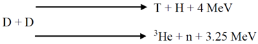
Either of this reaction may happen with same probability. Ignition temperature of this reaction is about 10 times higher than former i-e 5 x 10⁸ K.
From (1),
Total energy released is 17.58 MeV or 7.823961 x 10⁻¹⁶ Wh (1 MeV = 4.45049X10⁻¹⁷ Watt hour)
Mass of H2 = 1.00784 amu = 1.67356 x 10⁻²⁴ g
Mass of D2 = 2.014 amu = 3.344325 x 10⁻²⁴ g
Mass of Tritium = 3.016 amu = 5.008185 x 10⁻²⁴ g
Combining (2) and (3)
D2 + T = 3.344325 x 10⁻²⁴ g + 5.008185 x 10⁻²⁴ g = 8.342185 x 10⁻²⁴ g
Thus,
8.342185 x 10⁻²⁴ g produces 7.823961 x 10⁻¹⁶ Wh = 7.823961 x 10⁻²² MWh
7.823961 x 10⁻²² MWh is produced from 8.342185 x 10⁻²⁴ g or
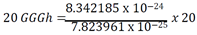
7.823961 x 10⁻²⁵ GWh is produced from 8.342185 x 10⁻²⁴ g
7.823961 x 10⁻²⁵ GWh = 8.342185 x 10⁻²⁴ g
8.342185 x 10⁻²⁴
20 GWh = 20 𝑥 10.662355039857 g
20 GWh = 213.24710079714 g
Now,
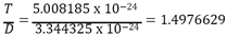
𝑇 = 1.4976629 𝐷
If
𝑇 + 𝐷 = 213.24710079714 𝑔
Substituting
1.4976629 𝐷 + 𝐷 = 213.24710079714 𝑔
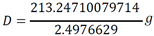
2.4976629 𝐷 = 213.24710079714 𝑔
𝐷 = 85.3786557013518 𝑔
Substituting above
𝑇 = 1.4976629 𝑥 85.3786557013518 𝑔
𝑇 = 127.8684450957882 𝑔
Considering 30% loss
𝑇 + 𝐷 = 277.221231036282𝑔
𝑇 = 166.22897862452466 𝑔
𝐷 = 110.99225241175734 𝑔
3. Construction, Making and Working
Construction and making of fusion devices involve precise design, control and mastery of techniques, practices, and procedures of materials, processes, and engineering of metals and materials. Their working constitutes careful understanding of principles of fission triggering, explosion, scatter, and ignition followed by / or simultaneously with shock wave focusing [12,13], trigger and target placement, mode of detonation and geometrical configuration of assembly (fission and fusion sub assembly). These are briefly described here.
3.1. Temperature and Energy Flux in a Fission Device
In order to understand fusion device working and explosion, it is important to understand fission device working and explosion. Primarily temperature and energy flux in a fissile fission device are of utmost importance and plays an important role. These results in multitude of configurations but fundamentally they rely on ignition and its use in explosion.
3.2. Ignition Problem
3.2.1. Ignition Temperature
Ignition of a fusion device is dependent on achieving critical temperature for it known as ignition temperature. This temperature is a function of amount and extent to which a suitable source (e.g. fission explosion, laser or chemical explosion) may be converged to a point. This convergence is achieved in many ways described in following. In addition to this, neutron flux is another important factor in achieving this. A large neutron flux produces a large amount of heat (both by inelastic scattering and neutron induced nuclear reactions) which contributes towards achieving ignition temperature.
3.2.2. Lawson Criteria
In addition to thermonuclear reactions, another criterion, known as Lawson criteria, must be satisfied in order for fusion device to work. For a thermonuclear assembly heated to ignition temperature, Lawson criteria may be defined as
nt > g (T)
where
n = a number
t = time for thermonuclear reaction g(T) = a known function of 
For DT reaction, g (T) has minimum at ~108K with  . At ignition temperature ~5 𝑥 107K with
  , For DD reaction,
. At ignition temperature ~5 𝑥 107K with , For DD reaction,
For its derivation, it is important to understand that all thermonuclear reactions must occur at temperature that is above the temperature for complete ionization. At this temperature, thermonuclear material emits very little radiation and is virtually optically transparent. The energy to heat thermonuclear material, mainly goes into kinetic particle energy with energy density equal to
εk = (3/2)(Z + 1)nkT
also,
Energy represented as energy density (εl) produced by thermonuclear reactions in time t during which thermonuclear material is inertially confined is given by
εl = 𝑛2𝑓𝑓(𝑇)𝑡
For a thermonuclear device to work, i.e., if more energy is to be released (or required) than required to heat thermonuclear plasma above its ignition temperature (blast in a device or controlled reaction in a reactor), the inequality
ε𝑙𝑙 > ε𝑘𝑘 a
must be satisfied. This is another form of Lawson criteria
A yet third form is
where
𝜌 = fuel density
r = radius
v = √𝑇
𝜌𝑟 ≥ a (7)
𝑛 𝖺 𝜌
𝑡 𝖺 𝑟⁄𝑣
For DT reactions, a ≅ 0.1 g / cm2.
3.3. Devices—Type and Configurations
3.3.1. Ordinary Device
Ordinary devices comprise of relatively simple configuration which is a compact mass in center surrounded by spherical shell which serves as housing. Critical mass of typical Pu239 device is about 11 Kg while radius of sphere is only 5 cm. In order to take maximum advantage of fission process and neutrons released, this core may be surrounded by another shell of material known as reflector. Typical material for this shell is Be or a combination (mixture) of Be and U235. This re focuses neutrons generated back onto core thus reducing critical mass considerably. Typically, by doing this mass (Pu239) required may be reduced to 4 Kg while radius of core is reduced to mere 3.6 cm. Typical upper limit of output from a fission device is 50 kT as it poses structural limitations at larger devices. In order to obtain higher output, a technique known as boosting is required.
Figure 1.
Schematic of ordinary (simple) spherical fission device. Configuration of components of a fission bomb. A - initiator (neutron source or generator), B - fissile core (plutonium and U235), C - tamper core reflector (U + Be), D - high explosive lens (shaped plastic charge), E - detonator.
Figure 1.
Schematic of ordinary (simple) spherical fission device. Configuration of components of a fission bomb. A - initiator (neutron source or generator), B - fissile core (plutonium and U235), C - tamper core reflector (U + Be), D - high explosive lens (shaped plastic charge), E - detonator.
3.3.2. Booster Device
Booster devices [3] are relatively new addition to modifications to design of fission devices. They make use of principle of fusion. In some scenarios, it is called fusion device. On this type of device (Figure 2), a small amount of fusion material is injected or placed into or at the center of fissile Pu239 as it is exploding with the result that exploding power is boosted, typically tenfold. Neutrons produced in fusion are used to produce more fission in Pu239. The advantage of this configuration is, it increases the inertial confinement time of the thermonuclear material, which is compressed by an ingoing spherical implosion wave. This compression effect is quite important because

where, R = thermonuclear reaction
A compression may be also indispensable for more exotic thermonuclear explosives [5]. Boosted devices are therefore more compact and sophisticated and efficient devices. Typically, 5 – 10 times more efficient. Their upper limit of output is 500 kT. For more output, fusion or thermonuclear devices are used in which an ordinary fission device may only serve the purpose of ignition (Figure 3).
Figure 2.
(a) Schematic of booster compact spherical fission device. A - initiator (neutron source or generator), B - fissile core (plutonium and U235), C - tamper core reflector (U235 + Be), D - high explosive lens (shaped plastic charge), E - detonator, F – tritium container, G - tritium feed into core of device. (b) Another schematic.
3.3.3. Two Stage, Modified Teller—Ulm or Mike Ivy Configuration
This is elaborately discussed in earlier study [9]. Interested reader is referred to it. Typically, it is two stage devices with fission device detonating and exploding at one end and fusion at other (Figrue 3). Typically, such device does not have theoretical upper limit as there is no critical mass. Former Soviet Union tested one such device 1962 in Arctic with explosive yield equivalent to about 60-million-ton TNT (60.000,000 ton TNT) [11].
Figure 3.
Schematic of two stage Modified Teller – Ulm or Mike Ivy fusion device [11].
Figure 3.
Schematic of two stage Modified Teller – Ulm or Mike Ivy fusion device [11].
3.3.4. Polyhedron Configuration
Polyhedron configuration consists of placing multiple fission devices in a fashion that upon detonation they produce a shock wave which become convergent [14,15,16], (e.g. cylindrical [17,18,19] in a medium (e.g. air [20,21,22], argon [23], gases [24], water [25], space)), is stabilized [26], and spherically symmetric in the limiting case of an infinite number of fission devices. They may be achieved by various means such as piston (spherical or cylindrical [27]) driven [28]. A spherical convergent wave is the aim which may be described by Gurderley’s [29] self-similar solution [30]. It has various configurations (e.g. blast wave [31] from a charge [32] of various geometries [33]). Smallest possible devices is 04 placed at the corners of regular tetrahedron. In said configuration, six is more optimized value, otherwise divergence from spherical symmetry becomes too large (Figure 4).
3.3.5. Ignition by Implosion (Prandtl-Meyer Configuration)
This is configuration in which ignition is achieved by micoexplosions which is achieved by imploding a disk of relativistic electrons [34]. Its exact mathematical theory is described earlier in a work by Busemann. Here only salient features and simplified treatment is described. In Figure 5, lines 1 and 2 represent the rays of outgoing and incoming shock waves, respectively, within an oval cavity representing Prandtl-Meyer ellipsoid. By the intersection of the incoming wave at one particular point P with the wall of the Prandtl – Meyer a sample, or Riemann, wave is emitted from P under the Mach angle
µ = arcsin (1/M)
Case I: In general case, a stationary shock wave front is formed if and when envelope is formed by intersection of Mach lines of reflected waves at different locations. Case 2: When all the Mach lines of reflected waves meet in just one point, spherical convergent shock wave is formed in the vicinity of this point. In a Prandtl – Mayer ellipsoid, geometrically two such points exist. First is the one from which outgoing detonation waves originate and second is the one into which all reflected waves converge. These two points are thus foci of Prandtl – Meyer ellipsoid. This ellipsoid becomes mathematical ellipsoid for small amplitude waves corresponding to acoustic approximation.
3.3.5.1. Determination of Wall Shape of Ellipsoid
Consider an incoming ray of a Mach number M strikes with inner wall shape of ellipsoid. This makes an angle θ with the wall slope and Mach number M. It is described by integrated Prandtl – Meyer expression for a supersonic flow along a curved wall.
𝛾𝛾 = specific heat ratio (𝛾𝛾 = 3 / 4 for a black body radiation dominated plasma)
θ0 = π / 2 (if M0 = Mach number at the vertex point of ellipsoid (point of placement of fission device next to focus). M0 ≈ 1 as shock waves forming fire ball from adjacent focus (point of placement of fission device) have not yet expanded enough to become supersonic)
Shape of Prandtl – Meyer ellipsoid is determined by the condition that outgoing shock waves from first focus must meet in the second focus. This condition can be best described by bipolar coordinates r1, r2 and angles α and β, such as
α + β = M(F)
with
M(F) ≡ θ(M) + µ(M)
The change in density along a variable Mach number flow is given by

Inserting, M0 = 1 and 
ρ⁄ρ0 = [7/(6 + 𝑀2)]3
Now, assume flow is completely isentropic, then, ρ is a symmetric function of 𝑟1 and 𝑟2. With this, for a large– amplitude spherical expansion wave,  and
and
and
Where, r0 = distance between focus and adjacent vertex point of M = 1
Eliminating  from (9) and (10)
from (9) and (10)
Assume, L = distance between two foci
𝑟1𝑐𝑜𝑠𝛼 + 𝑟2𝑐𝑜𝑠𝛽 = 𝐿
𝑟1𝑠𝑠𝑠𝑛𝛼 = 𝑟2𝑠𝑠𝑠𝑛𝛽
These set of four equations, (8,11–13) with five unknowns r1, r2, α1, α2 and M then reduces to one relation between two unknowns r1, r2 giving the wall curve of Prandtl – Meyer ellipsoid in bipolar coordinates. In practical scenario, shape of cavity will be different since part of cavity will be ablated. This ablation effect will require an asymmetric cavity and correct form of cavity must be determined by complex computer calculations and multitude of nuclear explosive tests.
3.4. Shock Wave Focusing—Other Configurations
Shock waves may also be focused by alternative configurations in which they are contained in mirrors. These are explained below. A very common configuration is lens. In this (Figure 6), divergent shock waves are focused by converging them at a particular point by virtue of passing through rarer and denser mediums using mirror type focusing. From the theory of plane shock waves, it is inferred that for a given temperature T, behind the shock front
Where
A = Atomic weight of material for through which shock wave propagates
v = Velocity of propagation
Now, Relative refractive index (n) may be defined as follows

If
A1 = Atomic weight of first medium A2 = Atomic weight of second medium
A1 = Atomic weight of H2 = 1, A2 = Atomic weight of D2 = 4, n =2
Also, density ratio = 
Both mediums must be chosen such as to avoid a pressure jump that requires 𝜌2 = 𝜌1
If 𝜌1 ≫ 𝜌2, the second medium may be blown away or
If 𝜌1 ≪ 𝜌2, most of incident shock wave energy is reflected.
Since  , condition 𝜌2 = 𝜌1
, condition 𝜌2 = 𝜌1Implies
Figure 6.
Lens configuration [11]. F: Fission source, W: wall, 𝜌: density of medium, A: Atomic weight, T: thermonuclear explosive.
Figure 6.
Lens configuration [11]. F: Fission source, W: wall, 𝜌: density of medium, A: Atomic weight, T: thermonuclear explosive.
Another common configuration is cone. This utilizes cylindrical implosion. In this cone or conical shape, geometry is tailored to make best use of spherical symmetry and convergence of shock wave. Supersonic Prandtl – Meyer flow generated from source (fission explosive (F)) is maneuvered in a cone around a central manifold and its walls (W) which is engineered to enable and facilitate their focusing by passing around contours and outer surface of cone (C) such as they generate cylindrical implosion by meeting at a predefined point (thermonuclear explosive (T)).
Figure 7.
Cone configuration [11].
Figure 7.
Cone configuration [11].
For larger yields further modified configurations are utilized. One such is Multi module. It consists of following main parts. (1) Ignition Module (I) containing fission trigger, (2) Conical transient module C enlarging the thermonuclear deflagration front and (3) the main Thermonuclear explosive module. All these are surrounded by a tamp.
Figure 8.
Multi module.
Another one is Dry H device. This is adopted for further larger yields. This is a variant of multimode configuration in such a way that spherical symmetry is achieved by Prandtl – Meyer ellipsoid in left portion (Ignition module) (Figure 9). Fuel and its encapsulation are also changed to 6LiD and 238U respectively.
Another variant of multimode configuration which make use of tetrahedron at one end to achieve spherical symmetry and convergence of shock wave is called tetrahedron configuration (Figure 10).
Similar shock wave focusing may be achieved in another configuration known as multi shell (Figure 11). It simplifies the geometry and make device more compact and size efficient.
Another special configuration – a special case of spherical or elliptical configuration, in which trigger, and target are changed is known as Neutron device. This makes use of special arrangement of trigger and target to achieve maximum output and yield. Target itself is changed from a fusion device to 6Li2DT encapsulated in 9Be (Figure 12).
Another device making use of target triggered by neutrons to achieve a thermonuclear reaction is known as autocatalytic configuration (Figure 13). This is due to the type of reaction occurring in such configuration thus drives its name. Target again is changed to 6LiDT encapsulated in 238U. This configuration controls Neutron flux efficiently as outer shell is 238U which is only fissionable by fast neutron and transmutates to 239Pu.
A variant of this makes use of mixing of fuel with each other in reaction chamber such as better homogenization is achieved. These are termed as compact devices (Figure 14). Certain changes are also made in trigger compartment (i.e., its size is increased to achieve better neutron focusing on target fuel). Fuel chamber is of small size and mixed fuel accommodated in it is also of small size. Mixture may consist of isotopes of H (e.g., 6LiD or 6LiT).
3.5.. Non Fission Ignition (Chemical Ignition) and Ablation
Ignition may also be achieved by other nonphysical means such as conventional chemicals. Many configurations are in use and may be utilized. One such is multi shell. This is similar to multi shell device described earlier except that it makes use of chemicals to achieve ignition and start the reaction.
Figure 15.
Multi shell chemical ignition device.
In these types of devices size and geometry have its own constraints. For example, chamber containing ignition source is considerably large as compared to fuel camber. Fuels are same as previously used i.e., 6LiD encapsulated in 238U. A variant of Prandtl – Meyer ellipsoidal making us of chemicals is known as Special chemical Prandtl – Meyer configuration (Figure 16). This is a special case of ellipsoid or Prandtl – Meyer configuration in which same ignition is achieve by a chemical reaction rather than fission device operation. Chemical for ignition is placed in different layers and shock waves generated from it are focused onto target by virtue of the ellipsoidal configuration.
A special class of spherical devices in which ignition is achieved by ablation and implosion are known as Ablation implosion or simply ablation devices. An ablated material is imploded onto a centrally placed spherical device such as explosion is achieved.
Figure 17.
Spherical ablative ignition device.
3.6. Lasers, Ion Beams and FGNW
These are class of devices which utilizes other physical means than chemical ignition to achieve ignition. For example, laser devices make use of high energy, focused laser light to achieve high gain used for ignition Their details may be found in literature cited [35,36]. Ion beam may also be used for same purpose. This is special method which utilizes intense ion beams for focusing and ignition. Their details may be found here [37,38,39,40]. These will be discussed elaborately in subsequent studies. Yet another are Fourth generation nuclear devices also known as fourth generation nuclear weapons (FGNW). These are [10] special devices which make use of special configurations, arrangements, arbitration and mechanisms to achieve enhanced ignition, high efficiency and high yield. Their details are discussed elsewhere.
3.7. Deployment
Deployment of these devices also constitute careful design and selection of parameters required for a certain scenario. These include, ready fixed site ground deployment, underground silo deployment, mobile launching, air drop and naval ship deployment. Based on each scenario, mechanisms of deployment also vary. Selection of particular war head and its configuration and setting in each mode of deployment determines whole mechanism. Various optimized war head geometrical configurations are designed to reduce air drag, dampening, increase velocity, acceleration, impact, damage upon impact, minimize collateral, splash, and debris. This also depends on and is very strong function of type of carrier for fusion device such as (a) missiles (liquid fuel fired, solid fuel fired (solid grain or solid rocket motor), their altitude, range, trajectories, and flight paths, (b) canons or (c) air crafts.
3.8. Detonation
Detonation of these include, aerial drop, surface detonation, near surface detonation, subsurface detonation, underwater detonation, and open-air blast. Various treaties prohibit the detonation of these devices (either sole fission or fission and fusion combined). However, they are still used for test and research and development purposes.
4. Conclusion
Fusion device engineering has been an active area of research and owing to its importance, it is thoroughly researched here. Fusion device design based on amount of energy output release is determined. It is found that careful control and conversion of energy released determines and control fuel, its amount, distribution, ignition, ignition mechanisms, device size, geometry, and configuration. This is vital factor and carefully considered here. Further later studies will follow design on the basis of energy release mechanisms, yield, and release rate (dy/dt).
References
- Winterberg, F., The Release of Thermonuclear Energy by Inertial Confinement: Ways Towards Ignition. 2010: World Scientific.
- Winterberg, F., General Relativistic Modification of the Lockheed Compact Fusion Reactor Concept. Fusion Science and Technology, 2020. 76: p. 141 - 144. [CrossRef]
- Gsponer, A., Fourth Generation Nuclear Weapons: Military effectiveness and collateral effects. 2005.
- Siracusa, J.M., Nuclear Weapons: A Very Short Introduction. 2008: OUP Oxford.
- Winterberg, F. and F.E. Foundation, The Physical Principles of Thermonuclear Explosive Devices. 1981: Fusion Energy Foundation.
- Winterberg, F.M. On Thermonuclear Micro-Bomb Propulsion for Fast Interplanetary Missions. 2013.
- Winterberg, F.M., Nuclear microbomb propulsion for manned deep space exploration with return travel. Acta Astronautica, 2019. [CrossRef]
- Winterberg, F., Matter–antimatter gigaelectron volt gamma ray laser rocket propulsion. Acta Astronautica, 2012. 81(1): p. 34-39. [CrossRef]
- Rafique, M.M.A., Materials for Outer Shell of 1.170 GWh (1.00669 Kilo Ton TNT) Fusion Device-Weight Basis. 2021.
- Gsponer, A. and J.P. Hurni. The physical principles of thermonuclear explosives , inertial confinement fusion , and the quest for fourth generation nuclear weapons. 2010.
- Barnaby, F., How to Build a Nuclear Bomb: And Other Weapons of Mass Destruction. 2004: Nation Books.
- Sandel, F.L., et al., Focusing of fast plasma shock waves. The Physics of Fluids, 1975. 18(8): p. 1075-1076. [CrossRef]
- Winterberg, F., Ignition by shock wave focusing and staging of thermonuclear microexplosions. Nature, 1975. 258(5535): p. 512-514. [CrossRef]
- RAIZER, I. and I. ZELDOVICH, Physics of Shock Waves and High- Temperature Hydrodynamic Phenomena. Volume 1(Physics of shock waves and high temperature hydrodynamic phenomena, Volume 1). 1966.
- Lazarus, R. and R. Richtmyer, Report la-6823-ms. Los Alamos Sci. Lab, 1977. 680.
- Sharma, V.D. and C. Radha, Similarity solutions for converging shocks in a relaxing gas. International Journal of Engineering Science, 1995. 33(4): p. 535-553. [CrossRef]
- Wu, J.H.T., R.A. Neemeh, and P.P. Ostrowski, Experimental Studies of the Production of Converging Cylindrical Shock Waves. AIAA Journal, 1980. 18(1): p. 47-48. [CrossRef]
- Payne, R.B., A numerical method for a converging cylindrical shock. Journal of Fluid Mechanics, 1957. 2(2): p. 185- 200. [CrossRef]
- Shabouei, M., R. Ebrahimi, and K.M. Body, Numerical solution of cylindrically converging shock waves. arXiv preprint arXiv:1602.02680, 2016.
- Takayama, K., H. Kleine, and H. Grönig, An experimental investigation of the stability of converging cylindrical shock waves in air. Experiments in Fluids, 1987. 5(5): p. 315-322. [CrossRef]
- Kinney, G.F. and K.J. Graham, Explosive Shocks in Air. 1985: Springer, Verlag. [CrossRef]
- Stoner, R.G. and W. Bleakney, The Attenuation of Spherical Shock Waves in Air. Journal of Applied Physics, 1948. 19(7): p. 670-678. [CrossRef]
- Eliasson, V., et al., Light emission during shock wave focusing in air and argon. Physics of Fluids, 2007. 19(10): p. 106106. [CrossRef]
- Steiner, H. and W. Gretler, The propagation of spherical and cylindrical shock waves in real gases. Physics of Fluids, 1994. 6(6): p. 2154-2164. [CrossRef]
- VonNeumann, J. and R.D. Richtmyer, A Method for the Numerical Calculation of Hydrodynamic Shocks. Journal of Applied Physics, 1950. 21(3): p. 232-237. [CrossRef]
- Perry, R.W. and A. Kantrowitz, The Production and Stability of Converging Shock Waves. Journal of Applied Physics, 1951. 22(7): p. 878-886. [CrossRef]
- Dyke, M.V. and A.J. Guttmann, The converging shock wave from a spherical or cylindrical piston. Journal of Fluid Mechanics, 1982. 120: p. 451-462.
- Ramsey, S.D. and R.S. Baty, Piston driven converging shock waves in a stiffened gas. Physics of Fluids, 2019. 31(8): p. 086106. [CrossRef]
- Guderley, K., Starke kugelige und zylindrische verdichtungsstosse in der nahe des kugelmitterpunktes bnw. der zylinderachse. Luftfahrtforschung, 1942. 19: p. 302.
- Nath, G. and S. Singh, Similarity solutions for magnetogasdynamic cylindrical shock wave in rotating ideal gas using Lie Group theoretic method: Isothermal flow. International Journal of Geometric Methods in Modern Physics, 2020. 17(08): p. 2050123.
- Brode, H.L., Numerical Solutions of Spherical Blast Waves. Journal of Applied Physics, 1955. 26(6): p. 766-775. [CrossRef]
- Brode, H.L., Blast Wave from a Spherical Charge. The Physics of Fluids, 1959. 2(2): p. 217-229. [CrossRef]
- Johnson, C., et al., Effect of explosive charge geometry on shock wave propagation. AIP Conference Proceedings, 2018. 1979(1): p. 150021.
- Winterberg, F., Thermonuclear microexplosion ignition by imploding a disk of relativistic electrons. Physics of Plasmas, 1995. 2(3): p. 733-740. [CrossRef]
- Tabak, M., et al., Ignition and high gain with ultrapowerful lasers*. Physics of Plasmas, 1994. 1(5): p. 1626-1634. [CrossRef]
- Winterberg, F., Laser Ignition of an Isentropically Compressed Dense Z-Pinch. Zeitschrift für Naturforschung A, 1999. 54(8-9): p. 459-464. [CrossRef]
- Winterberg, F., Thermonuclear micro-explosions with intense ion beams. Nature, 1974. 251(5470): p. 44-46. [CrossRef]
- Winterberg, F., Adiabatic wall focusing of intense ion beams for the ignition of thermonuclear microexplosions. Zeitschrift für Physik A Atoms and Nuclei, 1977. 282(1): p. 3-6. [CrossRef]
- Winterberg, F., Production of dense thermonuclear plasmas by intense ion beams. Plasma Physics, 1975. 17(1): p. 69- 77. [CrossRef]
- Winterberg, F., The Possibility of Producing a Dense Thermonuclear Plasma by an Intense Field Emission Discharge. Physical Review, 1968. 174(1): p. 212-220. [CrossRef]
Figure 4.
Schematic polyhedron configuration (fission devices are placed at fixed location around a central fusion device such a way the shock wave produced from them is focused on fusion device and is used in achieving ignition) [11]. F: fission device, R: wave reflector, T: thermonuclear explosive.
Figure 5.
Schematic Prandtl – Meyer configuration (One fission device (F) is placed at one end of ellipse in such a way that shock wave generated from it is focused on fusion device on other end after reflecting from wall (W). Spherical implosion onto thermonuclear explosive (T) is responsible for operation [11]. M is Mach. number of hypersonic flow of divergent detonation wave at point P, θ is angle between the wall slope and incoming ray; r1 and r2 are the rays of shock wave.
Figure 9.
Dry H Configuration.
Figure 10.
Tetrahedron configuration.
Figure 11.
Multi shell configuration.
Figure 12.
Neutron device.
Figure 13.
Autocatalytic device.
Figure 14.
Non – Autocatalytic device (compact device).
Figure 16.
Ellipsoidal chemical ignition device.
Disclaimer/Publisher’s Note: The statements, opinions and data contained in all publications are solely those of the individual author(s) and contributor(s) and not of MDPI and/or the editor(s). MDPI and/or the editor(s) disclaim responsibility for any injury to people or property resulting from any ideas, methods, instructions or products referred to in the content. |
© 2023 by the authors. Licensee MDPI, Basel, Switzerland. This article is an open access article distributed under the terms and conditions of the Creative Commons Attribution (CC BY) license (http://creativecommons.org/licenses/by/4.0/).
Copyright: This open access article is published under a Creative Commons CC BY 4.0 license, which permit the free download, distribution, and reuse, provided that the author and preprint are cited in any reuse.


