

Submitted:
12 November 2026
Posted:
17 November 2026
You are already at the latest version
Abstract
This article proposes a Direct Torque Control strategy based on Space Vector Modulation (DTCSVM). This approach offers advantages over conventional methods by improving system performance while significantly reducing electromagnetic torque and stator flux ripples. To further assess the impact of conventional Direct Torque Control (C-DTC) and DTC-SVM on power quality, a Total Harmonic Distortion (THD) analysis of the stator currents was conducted. The performance of both control strategies was evaluated under variations in stator flux and electromagnetic torque. The results demonstrate that the proposed DTC-SVM technique offers several advantages, including a fast dynamic response, a relatively simple implementation algorithm, and a constant switching frequency. Overall, the simulation results reveal improved control performance and confirm the effectiveness of the proposed strategy. The DTC-SVM scheme was validated through simulations conducted using MATLAB/Simulink.
Keywords:
wind energy
; space vector modulation (SVM)
; conventional direct torque control (CDTC)
; doubly fed induction generator (DFIG)
; vector control (FOC)
; total harmonic distortion (THD)
1. Introduction
Over the past thirty years, several control strategies have been developed to control asynchronous machines. These methods, called “stator flux orientation control,” offer performance equivalent to that achieved by direct current machines. In recent years, the developments of new techniques have allowed the realization of much more advanced control structures. The most recent steps in this direction are those grouped under the term direct torque control (DTC: Direct Torque Control).
TAKAHASHI and later developed for other applications. The objective was to eliminate the internal blocks and the modulation block by replacing them with a switching table whose inputs are the errors between the measurements made and the reference values [1].
The initial stage of the Direct Torque Control (DTC) strategyisimplemented on the rotor-side static Pulse Width Modulation (PWM) converter. In this control configuration, the converter and the machine are treated as an integrated system, with the control vectorcomposed of discreteswitching states thatdirectlygovern the rotor operation. This approachoffers notable advantages, includingrapiddynamicresponse and reducedsensitivity to machine parameter variations.
To address the limitations inherent in classical DTCparticularly the significant torque and flux ripples and computationalcomplexitywe have proposed an enhanced technique based on Space Vector Modulation (DTC-SVM). This method imposes a constant switchingfrequency, therebymitigating torque and flux oscillations whileimprovingoverall control performance.
The DTC strategyisrelativelystraightforward to implement, as itrequires the computation of electromagnetic torque and rotor flux amplitudes solelyfrom rotor-related variables. Furthermore, this control technique eliminates the need for conventional PWM implementation on the inverter, therebycontributing to improvedregulation of the controlledquantities [2].
Simulation results showed that DTC provides good tracking performance thanks to the principle of hysteresis regulation of rotor flux and electromagnetic torque. However, it generates strong oscillations in these two controlled quantities due to the variation of the switching frequency. In order to overcome the severe constraints of computation time and to improve the limits of the classical DTC technique, the proposed technique allows to reduce rotor flux oscillations and electromagnetic torque by imposing a constant modulation frequency [3]. This proposed method called DTC-SVM (Space Vector Modulation) with constant frequency modulation [4].
In this paper, the DTC control technique is proposed applied to the wind energy conversion system. The first one (DTC) is applied to the rotor-side PWM converter. This type of control considers the static converter associated with the machine as a set whose control vector is made up of the switching states. Its main advantages are the dynamic response time of the torque and rotor flux and the low dependence on the generator parameters. Improvements are also obtained on this last technique by the application of a vector modulation (DTC-SVM). The aim of this paper is to study and apply the control technique (DTC) to control the operation under optimal conditions of the wind turbine system. The implementation of this control is carried out using a switching table, synthesized from the study of the dynamics of the active and reactive instantaneous powers, thus ensuring simultaneous and precise control [5].
2. Math Overview of a Wind Energy Conversion System
The wind turbine conversion system has been illustrated in Figure 1.
the kinetic power available on the wind turbine is given by [6]:
In the context of wind energy conversion systems, the power coefficient Cp which characterizes the efficiency with which a wind turbine extracts kinetic energy from the wind—is a function of both the wind velocity and the turbine’s rotational speed. Typically, Cp values lie within the range of 0.35 to 0.59, as documented in the literature [7]. In such systems, particularly those employing Doubly-Fed Induction Generators (DFIG), wind energy is converted into electrical power. The associated power electronic converters play a crucial role in optimizing this energy conversion process by facilitating the transfer of the maximum extractable power to the electrical grid, contingent upon the prevailing wind conditions [8].
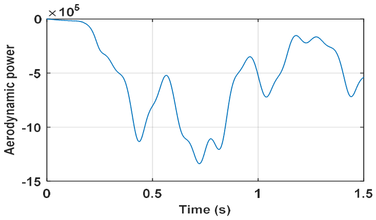
The following figures (Figure 1 and Figure 2) depict the relationship between the power coefficient Cp and the corresponding aerodynamic power extracted by the wind turbine. These graphical representations illustrate how variations in the power coefficient influence the amount of aerodynamic power harnessed from the wind, thereby providing insight into the turbine’s energy conversion efficiency under different operating conditions.
Figure 2.
Power coefficient.
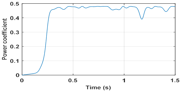
Figure 3.
Aerodynamic power.
3. Vector-Based Modeling of the DFIG and Its Converter Using Field-Oriented Control (FOC)
The mathematical expressions for the stator and rotor voltages in the Park (d-q) reference frame are presented as follows [9]:
The magnetic equations are:
Consequently, the electromagnetic torque is defined as [10]:
The vector is directly determined based on the states of the six power switches in the inverter and the DC voltage . The on/off status of these switches is represented by three Boolean control variables, denoted as , such that:
When the upper switch is closed while the lower switch is open.
When the upper switch is open and the lower switch is closed [11].
Therefore, the voltage vector can be expressed as:
The results of vector control simulations are given in the following figures:
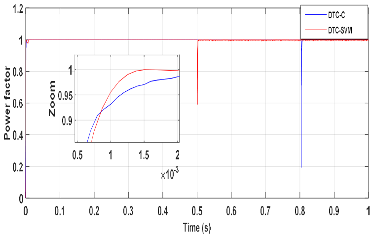
The simulation results shown in Figure 4 and Figure 5 demonstrate the effective performance of the FOC control in response to a setpoint change. Figure 6 and Figure 7 display the three-phase network voltages, with the corresponding current waveforms exhibiting a clear sinusoidal shape. As illustrated in Figure 8, the power factor under both control strategies varies with changes in active and reactive power. The total harmonic distortion (THD) of the stator current, presented in Figure 9, is measured at 1.45%.
4. Fundamental Dynamics of Torque Control
The fundamental principle involves directly regulating the torque of the DFIG by applying different voltage vectors from the inverter, which define its operating state. The two key control variables are the rotor flux and the electromagnetic torque, both managed using hysteresis controllers [12,13].
- A.
- Rotor flux control
In the stationary (α, β) reference frame attached to the rotor, the rotor flux of the doubly-fed induction generator is determined using the following equation [14,15]:
We obtain:
At high rotational speeds, the voltage drop caused by rotor resistance can be considered negligible, leading to the following expression:
Here, represents the flux vector at time t = 0, under the assumption that the rotor resistance remains constant. During a sampling period , the applied voltage vector is assumed to be constant, allowing us to express the following relationship:
With
During a sampling period, the rotor flux error ∆φr is directly proportional to the voltage vector applied to the machine’s stator. A two-level hysteresis comparator is employed for flux correction, ensuring that the tip of the rotor flux vector φr remains within a circular trajectory, as illustrated in Figure 10 [16,17].
- B.
- Electromagnetic torque control
Applying a Park transformation with power invariance, the electromagnetic torque during the control interval can be expressed as:
The variable is defined as the difference between the stator flux angle and the rotor flux angle , representing the angular separation between the two vectors.
Equation (10) indicates that the torque is a function of the magnitudes of the stator and rotor flux vectors, as well as their relative orientation
By expressing the stator and rotor flux vectors in complex form, the following relationship is obtained [18]:
To regulate the electromagnetic torque, a three-level hysteresis comparator—depicted in Figure 4—is utilized to control the machine’s operation during both forward and reverse rotation modes [8,9]. The estimation of the rotor flux is carried out using the measured electrical quantities from the Doubly-Fed Induction Generator (DFIG), specifically the rotor currents and voltages. The rotor flux is mathematically expressed as follows:
In the α/β reference frame, the rotor flux components are calculated as follows:
The electromagnetic torque can be estimated by utilizing the calculated rotor flux in conjunction with the measured rotor current. This estimation is based on the torque expression formulated as a function of both the magnetic flux and rotor current components. The corresponding relationship is derived from the following expression:
5. Enhancement of DTC-C by Vector Modulation (DTC-SVM)
In this section, space vector modulation (SVM) is employed to maintain a constant switching frequency in the operation of the rotor-side converter. The control of electromagnetic torque and rotor flux is achieved using two conventional Proportional-Integral (PI) controllers. This approach eliminates the need for hysteresis controllers and associated switching tables, thereby simplifying the control structure and improving the performance of the system [19,20].
This DTC-SVM technique has the advantages of vector control and classic DTC and makes it possible to overcome the problem of intermissions (discontinuities) of torque and flux. Proportional-integral regulators and the vector modulation technique are employed to achieve a fixed switching frequency and less torque and flux pulsation [21,22].
The fundamental principle of Space Vector Modulation (SVM) entails projecting the desired rotor voltage vector Vr onto the two adjacent active voltage vectors corresponding to neighboring switching states of the rotor-side converter. This projection enables the synthesis of the reference voltage vector through an appropriate combination of the adjacent vectors and their respective time durations, thereby ensuring accurate voltage control and smooth modulation.
The magnitudes of these vector projections are used to calculate the appropriate switching durations, which correspond to two non-zero active switching states of the converter. These durations are critical for accurately synthesizing the reference voltage vector within each modulation cycle.
If we denote these two times Ti and T+1, their sum must be less than the converter switching period Ts. To keep the switching frequency constant, a zero state of the converter on the machine side is applied for a period complementary to Ts [23,24].
A reference voltage vector is computed overall and approximated over a modulation period Ts by an average voltage vector . This average vector is generated by applying the two adjacent active voltage vectors along with the zero vectors V0 and V7. The eight voltage vectors, defined by different switch combinations, are illustrated in the (α, β) plane in Figure 11 [25,26].
The identification of the appropriate sector is carried out by determining the position of the reference voltage vector Vrefwithin the complex plane defined by the (αr-βr) axes. The location of this vector is characterized by its phase angle θ, which is used to ascertain the corresponding sector. The phase angle θis defined by the following relationship [27,28]:
Figure 12 presents a schematic representation of the proposed Direct Torque Control with Space Vector Modulation (DTC-SVM) strategy implemented for the Doubly-Fed Induction Generator (DFIG) system.
6. Simulation Results
To validate the effectiveness of the proposed DTC-SVM control strategy applied to the wind energy conversion system, a series of simulation tests were conducted under the same operating conditions as those used for the conventional Direct Torque Control (C-DTC) technique.
Figure 13 and Figure 14 illustrate low torque and flux ripples, particularly in the case of a power supply from an inverter controlled by the DTC-SVM. The torque and rotor flux follow their setpoints well with high dynamic and static performance (setpoint tracking, very fast response time).
Figure 15 and Figure 16 show respectively the waveforms of the stator and rotor currents supplied by the DFIG to the distribution network, as well as their harmonic spectra. These results confirmed the influence of the DTC-SVM control on the quality of the energy supplied to the electrical network. The harmonic distortion rate (Total Harmonic Distortion - THD) is 1.27% for the DTC-C and 1.01% for the DTC-SVM at the stator current level (Figure 13 and Figure 14) is less than 5%, which means a good quality of energy supplied to the network [29].
From the Figure 19, the power factor is much more stable for DTC-SVM than the classical DTC-C control.
Figure 15.
Stator current with the C-DTC.
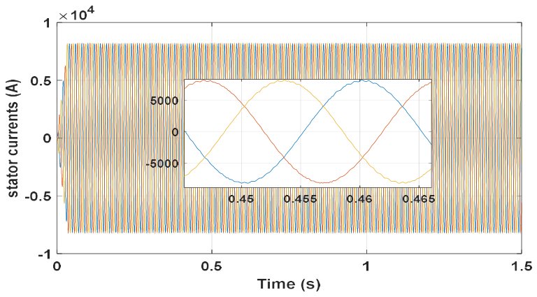
Figure 16.
Rotor current with the C-DTC.
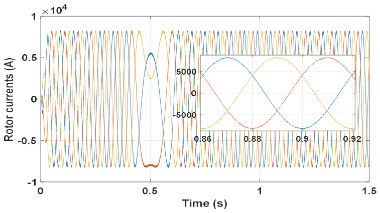
Figure 17.
THD (C-DTC).
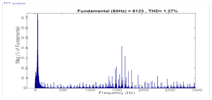
Figure 18.
THD (DTC-SVM).
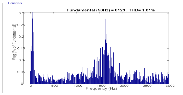
Figure 19.
Power factor (DTC-C, DTC-SVM).
7. Robustness Tests
To test the robustness of the DTC-SVM control of the DFIG, we also studied the influence of parameter variations on the control performance. A comparison between the two types of control (C-DTC and DTC-SVM) is performed in this test. To this end, the DFIG model parameters were varied as follows:
- ✓
- Influence of variation in rotor and stator resistance Rr and Rs+100%;
- ✓
- Influence of variation in mutual inductance Lm(-15%);
- ✓
- Influence of variation in rotor inductance Lr(-15%);
- ✓
- Influence of variation in stator inductance Ls(15%).
Finally, the results of the robustness tests (Figure 20 and Figure 21) show that the DTC-SVM is more robust than the DTC-C in the presence of parametric variations of the DFIG. These results allow us to conclude that the DTC-SVM control is the most effective in reducing the torque and rotor flux ripple compared to the conventional C-DTC control.
Table 1 presents a comprehensive comparative analysis between the Conventional Direct Torque Control (C-DTC) and the Direct Torque Control based on Space Vector Modulation (DTC-SVM) with respect to key performance metrics, including setpoint tracking accuracy, robustness to system disturbances, and Total Harmonic Distortion (THD). Among the two control strategies, the DTC-SVM-based wind energy conversion system demonstrated superior overall performance. However, it is noteworthy that, due to the implementation of the proposed fractional-order control approach, the THD values achieved by both C-DTC and DTC-SVM remain well within the acceptable threshold of 5%, as stipulated by the IEEE 519™-2014 standard [29].
8. Conclusion
The Direct Torque Control (DTC) strategyoffers a relatively simple implementationframework. It enables the computation of electromagnetic torque and rotor flux amplitudes usingonly rotor-related variables, there byreducing the need for complexmeasurementsystems. Moreover, DTC eliminates the requirement for pulse width modulation (PWM) in the inverter control, whichcontributes to improvedregulation of key system variables.
Simulation resultsdemonstratethat the conventional DTC approachachieves effective tracking performance, primarily due to itshysteresis-basedregulation of electromagnetic torque and rotor flux. However, a significant drawback of thismethodis the presence of pronounced oscillations in both torque and flux, which are attributed to the variable switchingfrequencyinherent in classical DTC schemes.
To overcome the severe computational time constraints and improve the shortcomings of DTC-C control, the direct control technique has been combined with a modulation method. Simulation tests clearly illustrate the improvements made by DTC-SVM compared to conventional (DTC-C). The simulation results of the DTC-SVM control confirmed the improvement in performance and the advantages, namely, control of the switching frequency. The comparative study between the proposed controller and the conventional C-DPC and DTC-SVM methods demonstrates that the proposed DTC-SVM is highly effective in stabilizing the system. Consequently, this approach has the potential to enhance the integration and utilization of wind energy.
References
- Rapport, “Le BaromètreEolien; Systèmes Solaires, Journal des Energies Renouvelables”, N°183, Union Européen, Février 2008.
- L. Tuan, M.Q. Duong, G.N. Sava, V. Tanasiev, “Optimization of renewable energy sources operation in Vietnam’s electricity market, “Rev. Roum. Sci. Techn. – Électrotechn. Et Énerg., 65, 4, pp. 221-217, 2020.
- S. Abdelmalek, L. Barazane, A. Larabi, “Faultdiagnosis for a doubly Fed induction generator,” Revue Roumaine des Sciences Techniques–Électrotechnique et Énergetique, 61, 2, pp. 159–163 (2016).
- H. Nian, Y. Song, P. Zhou, and Y. He, “Improved direct power controlof a wind turbine driven doubly fed induction generator during transientgrid voltage unbalance,” IEEE Trans. Energy Convers., vol. 26, no. 3,pp. 976–986, Sep. 2011. [CrossRef]
- S. Arezki, M. Boudour, “Study and regulation of dc bus voltages of wind-photovoltaic system, Rev. Roum. Sci. Techn. – Électrotechn. et Énerg., 59, 1, pp. 35–46 (2014).
- Bachir1, a. Foitihzoubir,” Comparative analysis of robust controller based on classical proportional-integral controller approach for power control of wind energy system,” Revue Roumaine des Sciences Techniques–Électrotechnique et Énergetique, 63, 2, pp. 210–216 (2018).
- Ali m. Eltamaly, m. S. Al-saud, and Ahmed g. Abo-khalil, “Dynamic Control of a DFIG Wind Power Generation System to Mitigate Unbalanced Grid Voltage”, IEEE Xplore, IEEE, Page(s): 39091–39103.
- S. Siniscalchi-Minna, M. De-Prada-Gil, F. D. Bianchi, C. Ocampo-Martinez and B. De Schutter, “A multi-objective predictive control strategy for enhancing primary frequency support with wind farms”, IOP Conf. Series: Journal of Physics: Conf. Series 1037. 2018.
- Yaichi, A. Semmah, M. Djlaila, A. Harrouz, S. Mansouri, Y. Bakou, “Modelling and control of Doubly Fed Induction Machine, Application for a Wind Turbine System”, IEEE Xplore Digital Library, International Renewable and Sustainable Energy Conference (IRSEC), Marrakech, Morocco, 2016.
- OunissaAouchenni, Rabah Babouri, Kaci Ghedamsi, DjamalAouzellag,” Wind farm based on doubly fed induction generator entirely interfaced with power grid through multilevel inverter,” Rev. Roum. Sci. Techn.– Electrotechn. et Energ., 62, 2, pp. 170–174 (2017).
- Beddar, H. Bouzekri, B. Babes, H. Afghoul, “Real time implementation of improved fractional order proportional-integral controller for grid connected wind energy conversion system,” Rev. Roum. Sci. Techn.– Electrotechn. et Energ., 61, 4, pp. 402–407 (2016).
- Bachir, A-F, Zoubir, “Comparative analysis of robust controller based on classical proportional-integral controller approach for power control of wind energy system, “Rev. Roum. Sci. Techn.– Electrotechn. et Energ., 63, 2, pp. 210–216 (2018).
- Tapia, G. Tapia, “Modeling and control of a wind turbine driven doubly fed induction generator,” IEEE Transactions on Energy Conversion, vol. 18, no. 2, pp. 194–204, 2003. [CrossRef]
- Yaichi, A. Semmah, P. Wira, Y. Djeriri, “Super-twisting Sliding Mode Control of a Doubly-fed Induction Generator Based on the SVM Strategy”, PeriodicaPolytechnica Electrical Engineering and Computer Science, 2019, 63(3), pp. 178–190. [CrossRef]
- Izanlo, M. V. Kazemi, A. Gholamian, “A new method of predictive direct torque control for doubly fed induction generator under unbalanced grid voltage,” Rev. Roum. Sci. Techn.– Électrotechn. et Énerg., 63, 3, pp. 332–337, (2018).
- Y.K. Wu, W.H. Shu, H.Y. Cheng, G.T. Ye and D.C. Jiang, “Mathematical modelling and simulation of the DFIG-based wind turbine”, CACS International Automatic Control Conference, 2nd ed., vol.3, 2014, pp. 15-64.
- Hu, Y. Huang, D. Wang, H.Y. and X.Yuan, “Modeling of Grid-Connected DFIG-Based Wind Turbines for DC-Link Voltage Stability Analysis”, IEEE Transactions on Sustainable Energy, 2015, vol. 6, no. 4, pp. 1325-1336. [CrossRef]
- S. Bellarbi, D. Saheb Koussa, Fuzzy robust control of double fed induction generator with parameter uncertainties, Rev. Roum. Sci. Techn.– Électrotechn. et Énerg. 61, 4, pp. 367–371 (2016).
- Ibrahima NGOM, AliouneBadara MBOUP and Lamine THIAW,” Active and Reactive Power Control of Doubly Fed-Induction Generator Based on Variable Speed Wind Power Generation”, International Conference on Electrical, Control, Automation and Robotics ECAR 2018.
- Ahmad Khajeha, Zahra Shabani,” Adaptive Gain Scheduling Control of Doubly Fed Induction Generator Based Wind Turbines to Improve Fault Ride Through Performance”, International Journal of Industrial Electronics, Control and OptimizationVol. 1, No. 1, pp. 61-70, June 2018. [CrossRef]
- Azib, D. Ziane, T. Rekioua, A. Tounzi, Robustness of the direct torque control of double star induction motor in fault condition, Rev. Roum. Sci. Techn.– Électrotechn. et Énerg., 61, 1, pp. 147– 152, (2016).
- Aberbour, K. Idjdarene, Z. Boudries, Adaptable sliding mode control for wind energy application, Rev. Roum. Sci. Techn. – Électrotechn. et Énerg., 61, 3, pp. 258–262 (2016).
- M.J. Zandzadeh, A. Vahedi, “Modelling and improvement of direct power control of DFIG under unbalance grid voltage condition”, international journal of electrical power and energy systems, Vol. 59, pp. 58-68, Jan 2014. [CrossRef]
- Patel TejaskumarSharadbhai; Shubhrata Gupta, “Artificial Neural Network Based Control Of Doubly Fed Induction Generator For Active Filtering Capabilities”, IEEE Xplore, 2021 4th International Conference on Recent Developments in Control, Automation & Power Engineering (RDCAPE), Noida, India.
- Asri, Y. Mihoub, S. Hassaine, P. O. Logerais, A. Amiar, T. Allaoui, An adaptive fuzzy proportional integral method for maximum power point tracking control of permanent magnet synchronous generator wind energy conversion system, Rev. Roum. Sci. Techn. – Électrotechn. Et Énerg., 63, 3, pp. 320-325 (2018).
- Youssef Ait Ali; Mohammed Ouassaid, “Advanced Control Strategy of DFIG based Wind Turbine using combined Artificial Neural Network and PSO Algorithm”, IEEE Xplore, 2020 International Conference on Electrical and Information Technologies (ICEIT), Rabat, Morocco.
- Bogdan-Florin Florea, Ovidiu Grigore, Mihai Datcu1, “Learning online spatial exploration by optimizing artificial neural networks assisted by a pheromone map, “Rev. Roum. Sci. Techn.– Electrotechn. et Energ., 62, 2, pp. 209–214 (2017).
- Nanami GanaLantewa; NurraddeenMagaji, “Control of Doubly Fed Induction Generator of Variable Speed Wind Turbine System using Neural Network”, IEEE Xplore, 2018 International Conference and Utility Exhibition on Green Energy for Sustainable Development (ICUE), Phuket, Thailand.
- IEEE Standards Association “IEEE Std 519™-2014 IEEE Recommended Practice and Requirements for Harmonic Control in Electric Power Systems”, The Institute of Electrical and Electronics Engineers, Inc. (IEEE), New York, USA, 2014. [online] Available at: https://edisciplinas.usp.br/pluginfile.php/1589263/mod_resource/content/1/IEE%20Std%20519-2014.pdf [Accessed: 11 March 2018].
Figure 1.
Diagram of a wind energy conversion chain.
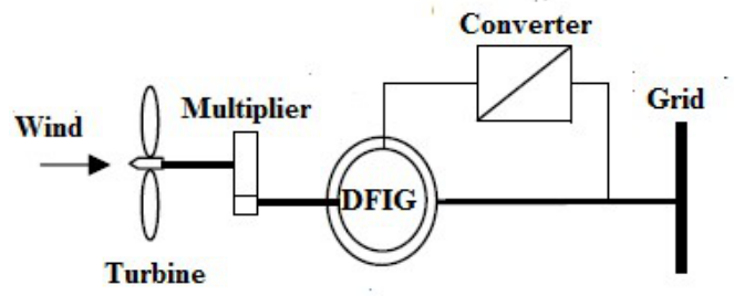
Figure 4.
Active power of DFIG.
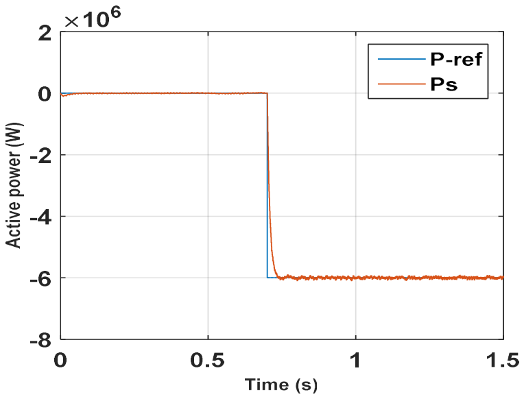
Figure 5.
Reactive power of DFIG.
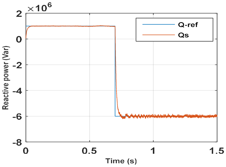
Figure 6.
Stator current of DFIG.
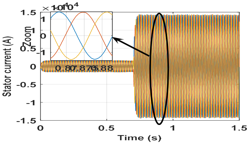
Figure 7.
Rotor current of DFIG.
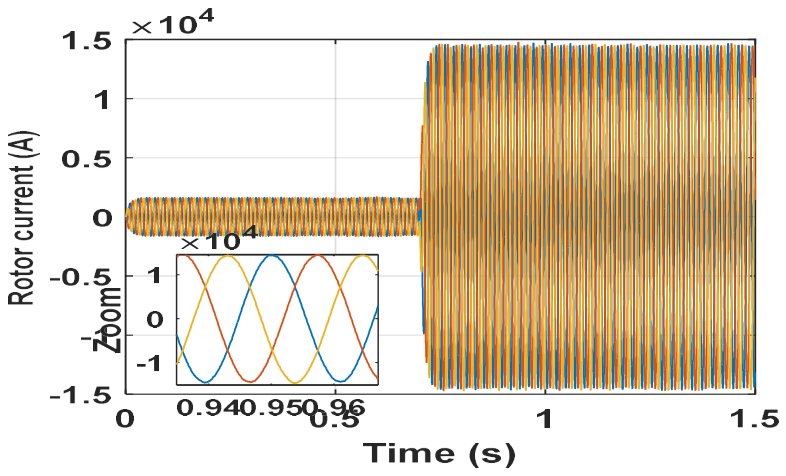
Figure 8.
Power factor.
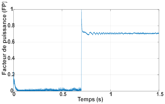
Figure 9.
THD (FOC).
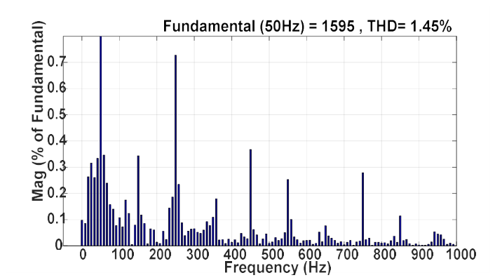
Figure 10.
Two-level hysteresis comparator (flux).
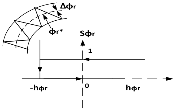
Figure 11.
Voltage vector representation in the (α, β) reference frame.
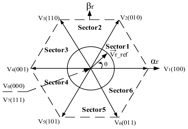
Figure 12.
Block diagram of the DTC-SVM control structure applied to DFIG.
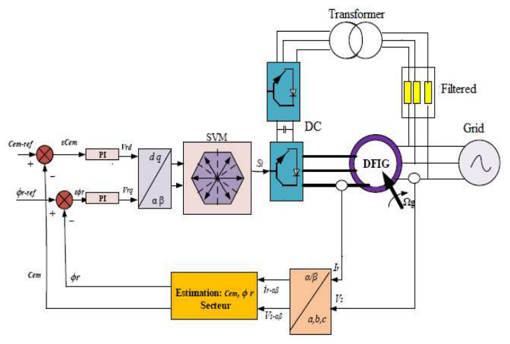
Figure 13.
Electromagnetic torque of the DFIG.
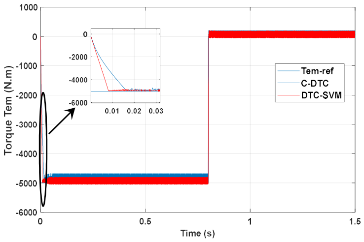
Figure 14.
Rotor flux of DFIG.
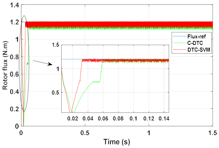
Figure 20.
Torque obtained.
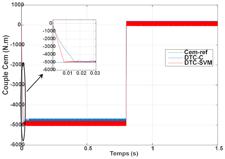
Figure 21.
Rotor flux obtained.
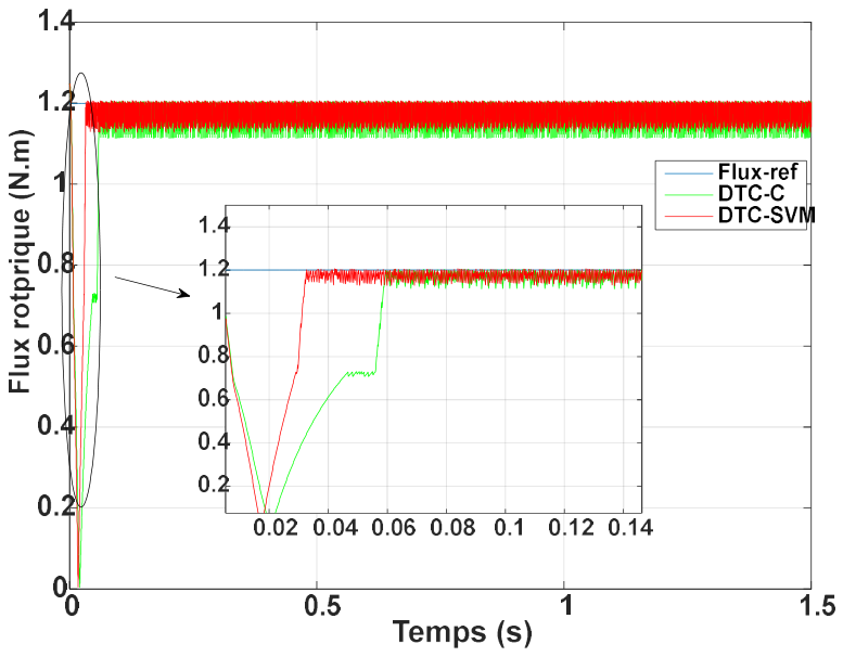

Table 1.
Comparison of the performances of the three regulators.
| Setpoint tracking | Robustness Tests | |||
| Performances | C-DPC | DTC-SVM | C-DPC | DTC-SVM |
| Response time Ps (ms) | 8 | 7 | 15 | 9 |
| Response time Qs (ms) | 15 | 30 | 60 | 30 |
| Active and reactive power control |
Directly controlled | Directly controlled | Directly controlled | Directly controlled |
| Computational complexity | Low | Low | Low | Low |
| Transitory response | Très bien | Très bien | Très bien | Très bien |
| THD (%) | 1.27 | 1.01 | 2.22 | 1.92 |
Disclaimer/Publisher’s Note: The statements, opinions and data contained in all publications are solely those of the individual author(s) and contributor(s) and not of MDPI and/or the editor(s). MDPI and/or the editor(s) disclaim responsibility for any injury to people or property resulting from any ideas, methods, instructions or products referred to in the content. |
© 2026 by the authors. Licensee MDPI, Basel, Switzerland. This article is an open access article distributed under the terms and conditions of the Creative Commons Attribution (CC BY) license.
Copyright: This open access article is published under a Creative Commons CC BY 4.0 license, which permit the free download, distribution, and reuse, provided that the author and preprint are cited in any reuse.