

Submitted:
14 November 2026
Posted:
16 November 2026
You are already at the latest version
Abstract
Wheelchair-accessible vehicles are commonly developed by modifying conventional platforms, introducing functional and aesthetic compromises. This study presents a user-centred engineering approach to designing a natively accessible passenger car with a non-medicalised identity. A questionnaire involving 100 stakeholders informed the identification of ten user requirements, prioritised through pairwise comparison and interdependence analysis. Six commercial wheelchair-accessible configurations were evaluated through technical benchmarking and Top-Flop analysis. Quality Function Deployment (QFD), the Kano model, TRIZ, and morphological analysis guided the translation of requirements into design solutions. Universal Accessibility and Adaptability received the highest importance weights (12% each), while Adaptability and Ease of Access showed the strongest interdependence. The Peugeot Rifter Horizon L2 RS achieved the highest Top-Flop balance (Δ = +2). QFD identified steering-wheel hand controls, access-system configuration, and interior reconfigurability as the leading technical priorities, with normalised scores of 10.00, 9.18, and 8.66, respectively. These priorities informed EVERY, an electric crossover concept integrating a pedal-free steering interface, a reconfigurable tunnel-free cabin, and an automated side-access platform. The resulting design framework connects stakeholder needs, engineering priorities, and vehicle architecture.
Keywords:
inclusive design
; vehicle accessibility
; wheelchair user
1. Introduction
Personal mobility supports access to education, employment, healthcare, and social participation and is recognised as a right of people with disabilities [1]. Approximately 1.3 billion people, corresponding to 16% of the global population, experience significant disability [2]. In Italy, approximately 3.1 million people report severe limitations in everyday activities [3].
Population ageing and the increasing prevalence of mobility limitations reinforce the need for accessible transportation [2]. Mobility assistive technologies support participation in everyday activities [4], while barriers within transportation systems can restrict independent mobility and social inclusion [5]. The development of accessible passenger vehicles has followed three main trajectories: dedicated vehicles with adapted driving controls, modifications of conventional production vehicles, and experimental architectures designed around wheelchair accommodation [6]. Among commercially available solutions, adaptations of conventional vehicle platforms remain widespread.
Wheelchair-accessible vehicles (WAVs) are commonly produced by converting minivans or light commercial vehicles through floor modifications, the installation of ramps or lifts, and the integration of wheelchair restraint systems and adapted driving controls [6,7]. Selecting appropriate driving adaptations according to individual capabilities remains an important engineering challenge [7]. Available solutions range from mechanical hand-operated controls to electronic interfaces incorporating alternative acceleration, braking, and steering arrangements.
Electronic vehicle-control architectures and advanced driver-assistance technologies provide opportunities to develop driving interfaces adapted to different user capabilities. Their integration into conventional vehicle platforms, however, leaves several architectural constraints associated with occupant access, interior packaging, and wheelchair accommodation.
A major challenge concerns the physical interaction between the occupant and the vehicle during boarding, transfer, and alighting. In a survey of older people with disabilities, 40% of respondents reported difficulty moving their legs into and out of passenger vehicles [8]. Subsequent studies have demonstrated the influence of ingress and egress strategies, occupant biomechanics, and vehicle geometry on accessibility and discomfort [9,10]. Assistive products also have a social dimension. Stigma can arise when the use of a device visibly distinguishes an individual from others [11]. Research on assistive technology has identified factors contributing to device abandonment [12], while studies of social interactions and product aesthetics have highlighted the importance of perceived stigma in the acceptance and use of assistive products [13,14].
These considerations are particularly relevant to wheelchair-accessible vehicles, where visible adaptations may influence both product appearance and user experience. Inclusive design and ability-based design provide complementary approaches to addressing these requirements. Inclusive design considers the needs of a broad population from the earliest design stages [15], while ability-based design focuses on adapting technological systems to users’ capabilities [16]. Automated driving could further extend independent mobility opportunities for people with disabilities [17], although attitudes towards autonomous vehicles vary according to individual circumstances, technological familiarity, and perceived benefits [18].
The automation of driving functions also introduces new requirements concerning accessible boarding, wheelchair securement, and occupant assistance [17]. Previous research has investigated autonomous-vehicle interfaces for older adults [19] and alternative ramp geometries for wheelchair accessibility in the built environment [20]. These contributions address relevant aspects of accessible mobility, while the coordinated integration of boarding, driving interaction, interior reconfigurability, and non-medicalised design within a passenger-car architecture remains an important research opportunity.
From a methodological perspective, Quality Function Deployment (QFD) establishes relationships between user requirements and engineering characteristics [21], the Kano model supports the interpretation of product attributes according to their contribution to user satisfaction [22], and TRIZ provides principles for addressing engineering contradictions [23]. The integration of these methods has been investigated in product development [24,25,26] and applied to transportation-related design challenges [27]. More recent approaches have further demonstrated the application of integrated QFD-TRIZ methodologies [28] and refined Kano classifications to assistive technology products [29]. A remaining challenge is to establish a traceable engineering process connecting stakeholder requirements, technical priorities, and their implementation in an integrated vehicle architecture.
Three gaps follow this review. (G1) Accessible cars are designed by adaptation; to our knowledge, no peer-reviewed study has derived a passenger-car architecture natively from the needs of wheelchair users, their caregivers and non-disabled buyers together. (G2) Desirability and stigma are discussed in the AT literature but are not operationalised as engineering requirements in vehicle design. (G3) Existing applications of QFD, Kano, and TRIZ in product development provide limited traceability between prioritised user requirements, engineering characteristics, and their implementation in integrated vehicle architectures.
The research question is: how can a car be designed to be accessible from the outset for wheelchair users, without a medicalised appearance, while remaining usable and desirable for a broad public? Four objectives were set: (O1) to elicit and quantify the needs of the four stakeholder groups involved in accessible car use; (O2) to translate these needs into prioritised technical characteristics through a transparent, auditable QFD-Kano-TRIZ chain; (O3) to embody the priorities in a vehicle concept; and (O4) to assess the engineering coherence of the proposed architecture through documented technical benchmarking and requirement-to-design traceability. The contribution is both applied (a natively accessible car architecture) and methodological (a verified, reproducible requirement-to-concept chain for inclusive vehicle design).
2. Materials and Methods
2.1 Research Framework
This study adopted a user-centred engineering design methodology to investigate the development of an automotive architecture integrating accessibility requirements from the earliest stages of product development. The research was based on the principles of inclusive design and ability-based design, which emphasise the adaptation of products and systems to users’ capabilities rather than requiring users to adapt to predefined technological solutions.
The proposed methodological framework combined stakeholder analysis, requirements prioritisation, technical benchmarking, Quality Function Deployment (QFD), the Kano model, the Theory of Inventive Problem Solving (TRIZ), and morphological analysis. QFD was employed to establish relationships between user requirements and engineering characteristics, while Kano and TRIZ supported the interpretation of user expectations and the resolution of technical contradictions. The research process comprised five principal phases:
- Identification and prioritisation of user requirements through stakeholder research.
- Definition of measurable engineering characteristics and assessment of applicable technical requirements.
- Benchmarking of existing wheelchair-accessible vehicles using verified technical specifications.
- Evaluation of technical priorities through QFD and Top-Flop analysis, followed by Kano and TRIZ-based interpretation.
- Development and preliminary engineering assessment of EVERY vehicle concept.
The overall methodological workflow is illustrated in Figure 1. The design process focused on three integrated subsystems: a pedal-free steering interface, a reconfigurable cabin with a continuous floor, and an automated side-access system. The present analysis examined the engineering rationale underlying this architecture using an updated technical benchmark. The technical benchmarking provided a documented reference for identifying existing accessibility solutions, engineering trade-offs, and opportunities for architectural integration.
2.2. Stakeholder Analysis and Identification of User Requirements
The identification of user requirements was based on an exploratory questionnaire involving 100 participants divided into four stakeholder groups: people with motor impairments (n = 30), caregivers (n = 20), professionals working with people with disabilities (n = 10), and community members (n = 40). The stakeholder groups, sample sizes and questionnaire domains are summarised in Table 1. The questionnaire investigated functional, ergonomic and experiential aspects of accessible mobility. Attention was given to vehicle entry and exit, wheelchair-to-seat transfer, driving controls, assistance requirements, perceived autonomy, and the aesthetic characterisation of accessible vehicles.
The questionnaire included five-point rating scales, single-choice and multiple-choice items, and open-ended questions. The different stakeholder groups received tailored sections addressing their respective experiences. The analysis of questionnaire responses, supported by the literature review, led to the identification of ten user requirements: universal accessibility, non-medicalised design, learnability, adaptability, multimodality, ergonomic comfort, ease of access, operational autonomy, perceived safety, and familiarity. These requirements were subsequently used as the basis for the engineering decision process.
The relative importance wi of the requirements was obtained from a reciprocal pairwise-comparison matrix (2 = row more important, 1 = equivalent, 0 = less important), with wi equal to the row total divided by the grand total. A second matrix rated the mutual dependence of requirements (0, 1, 3, 9); its normalised column totals measure how strongly each requirement is coupled to the others. All matrix scores in this and the following steps were assigned by two of the authors, using the survey distributions and the literature as explicit evidence for each judgement; the complete matrices are reported in the Supplementary Material.
2.3. Requirement Prioritisation and Interdependence Analysis
The relative importance of the identified requirements was assessed using a pairwise comparison matrix. For each pair of requirements, a score of 2 indicated greater importance of the row requirement, 1 indicated equal importance, and 0 indicated lower importance. Reciprocal comparisons were represented by complementary scores.
The importance weight of each requirement was calculated as:
where aij represents the comparison between requirements i and j, and n is the total number of requirements. The resulting weights were normalised so that their sum equalled one. The pairwise importance matrix and the interdependence matrix are reported in Table 2 and Table 3, respectively.
A second matrix was developed to describe relationships among requirements. Interdependence was expressed using a four-level scale corresponding to no relationship (0), weak relationship (1), moderate relationship (3), and strong relationship (9). The interdependence index for each requirement was calculated from the sum of the corresponding column entries and subsequently normalised against the maximum observed value. Both matrices were considered design decision instruments. Their scores reflected structured engineering judgements informed by stakeholder evidence and literature evidences.
2.4. Definition of Technical Characteristics
The user requirements were translated into engineering characteristics covering accessibility, vehicle architecture, interior configuration, driving controls, ergonomic interaction, assisted operations, and safety. The initial technical register comprised 32 characteristics identified during the original design process.
Each parameter was reviewed to establish its engineering definition, measurement unit, direction of preference, and applicability to different vehicle architectures. The characteristics were divided into quantitative parameters, objectively identifiable technical features, and qualitative characteristics requiring explicit assessment criteria.
Attention was given to distinguishing parameters that could otherwise lead to misleading comparisons. For example, ground clearance, floor height, access threshold height, clear doorway height and available interior headroom were treated as separate physical quantities. Similarly, the possibility of accommodating a wheelchair user as a passenger was distinguished from the possibility of driving independently, either directly from the wheelchair or following a transfer to a conventional driving seat.
Relevant regulatory and technical references were considered in defining safety-related requirements. These included ISO 10542-1:2012 [30] for wheelchair tiedown and occupant-restraint systems and ISO 15008:2017 [31] for the visual presentation of information within passenger-vehicle control systems. The standards were used to identify design requirements and verification criteria. Their consideration did not constitute evidence of regulatory compliance of the proposed concept, which would require further testing and validation.
2.5. Selection of Benchmark Vehicles and Technical Data Verification
An evidence-based benchmarking procedure was established to compare contemporary wheelchair-accessible vehicles (WAVs) and identify the technical characteristics of commercially documented accessibility solutions. The analysis considered vehicles derived from conventional passenger-car platforms and equipped with dedicated accessibility conversions. Side-entry and rear-entry configurations were included to represent alternative approaches to wheelchair boarding, interior arrangement and vehicle accessibility. Each benchmark alternative was defined by the combination of its base vehicle, conversion manufacturer, specific accessibility configuration and model year. Different conversions of the same base vehicle were treated as separate alternatives whenever they exhibited distinct technical characteristics.
The selection process prioritised configurations supported by official technical documentation issued by the vehicle manufacturer or authorised converter. Manufacturer specifications, technical manuals, dimensional drawings and applicable certification documents constituted the primary sources of information.
The initial selection included wheelchair-accessible configurations based on the Toyota Sienna Hybrid, Honda Odyssey, Chevrolet Traverse and Ford Tourneo Custom. The Toyota Sienna was considered in different side-entry configurations because its power-infloor and power-foldout systems present different access geometries. European rear-entry configurations were represented by vehicles such as the Ford Tourneo Custom Independence, for which detailed accessibility dimensions are published by the converter. The accessibility specifications of the selected conversions were obtained from the official technical documentation published by BraunAbility [32] and Allied Mobility [33,34].
Dedicated vehicles and historical accessibility concepts, including the Kenguru, were examined separately as architectural references. They were excluded from the principal quantitative benchmark when their technical specifications, commercial status or intended operating conditions were not directly comparable with contemporary commercial WAV configurations.
The original technical register comprised 32 characteristics covering accessibility, vehicle configuration, ergonomic interaction, driving controls, operational assistance and onboard systems. Each characteristic was examined to determine whether its value could be reconstructed from reliable and independently verifiable documentation for every selected benchmark vehicle. A complete-data inclusion criterion was adopted. A technical characteristic was retained in the quantitative benchmarking matrix only when a documented value was available for all selected alternatives and the values referred to equivalent physical quantities and measurement conditions.
Parameters that did not satisfy this requirement were excluded from the quantitative comparison, regardless of their availability for individual vehicles. Such parameters could nevertheless be retained in the technical register for qualitative discussion where relevant to the proposed architecture. When conflicting information was identified, preference was given to the most authoritative source referring directly to the vehicle configuration under examination. If two sources were equivalent in authority and applicability, the most recent publication was selected.
All quantitative data were expressed in consistent measurement units. Original values, unit conversions, source identifiers, model years and documentation dates were retained to ensure traceability. Table 4 presents the selected benchmark vehicles and their principal accessibility configurations. The complete technical data register, including excluded characteristics and documentary references, is provided in Supplementary Dataset S1.
2.6. Technical Benchmarking and Top-Flop Analysis
The verified technical characteristics were used to construct a comparative matrix of the selected vehicles. Only characteristics satisfying the complete-data criterion described in Section 2.5 were admitted to the quantitative analysis. This ensured that all vehicles were evaluated against the same set of documented parameters.
For each quantitative characteristic, the direction of preference was established according to its engineering and functional significance. For example, greater clear access width was considered advantageous because it provides additional space for wheelchair manoeuvring, whereas a lower access threshold was considered preferable for reducing boarding difficulty. The quantitative assessment included technical characteristics with documented numerical values and a clearly defined direction of preference. Categorical characteristics were retained to describe the accessibility configurations of the selected vehicles.
For each eligible characteristic, the best and worst documented performances were identified using the Top-Flop approach. A TOP was assigned to the vehicle or vehicles achieving the most favourable performance, while a FLOP was assigned to those presenting the least favourable performance. When two or more vehicles shared an identical best or worst value, the corresponding TOP or FLOP was assigned to all tied alternatives. Characteristics displaying identical values across the entire sample were considered non-discriminating and excluded from the scoring.
For each vehicle k, the difference between the total number of TOP and FLOP outcomes was calculated as:
where TOPk and FLOPk represent the number of favourable and unfavourable outcomes obtained by vehicle k, respectively. The resulting Delta values were used to describe the relative technical positioning of the selected vehicles within the analysed sample.
The Top-Flop analysis provides a comparative assessment of the selected vehicle configurations based on nine documented technical characteristics. Each characteristic contributes equally to the overall assessment, with TOP and FLOP outcomes assigned according to the predefined engineering criteria. The resulting Delta values highlight the distribution of favourable and unfavourable technical features across the benchmarked vehicles, providing a quantitative basis for identifying design trade-offs and opportunities for improvement. Because the comparison was restricted to characteristics documented for every vehicle, the results were dependent on the final set of eligible technical parameters. The resulting Delta values describe the relative technical positioning of the selected vehicles across the nine evaluated characteristics.
The Top-Flop results were subsequently examined to identify technological limitations and opportunities relevant to the development of integrated accessibility solutions. The benchmarking was not used to infer the experimental performance of EVERY concept, for which no physical prototype was available. Instead, it provided a documented technical reference against which the architectural choices of the proposed vehicle could be discussed. Table 5 reports the resulting technical benchmarking matrix, including the TOP, FLOP and Delta values for each selected vehicle.
2.7. Quality Function Deployment and What/How Matrix
Quality Function Deployment (QFD) was employed to translate the stakeholder requirements identified in Section 2.2 into engineering design priorities. The approach followed the principles of the House of Quality, which establishes systematic relationships between customer needs and technical characteristics.
A What/How matrix was constructed by combining the ten user requirements with twelve technical characteristics selected for their relevance to vehicle accessibility, interior adaptability, and driving interaction. These characteristics included vehicle architecture, access threshold height, ingress and egress time, number of interior configurations, wheelchair anchorage, grab handles, transfer seating, central tunnel configuration, access-system type, pedal arrangement, assisted operations, and steering-wheel hand controls.
Each relationship was assigned a score ranging from 0 to 10, using the discrete levels 0, 2, 4, 6, 8, and 10 to represent increasing degrees of contribution of a technical characteristic to a user requirement. The overall importance of technical characteristic j was calculated by combining the relationship scores with the requirement weights obtained from the pairwise comparison matrix:
where wi denotes the normalised importance of user requirement i, rij denotes the relationship score between requirement i and technical characteristic j, and n is the number of user requirements. The resulting scores were normalised relative to the highest-scoring characteristic:
The complete What/How relationship matrix and the resulting technical priority scores are presented in Table 6. The resulting values provided a relative measure of the contribution of each technical characteristic to the identified user requirements.
The What/How analysis was conducted independently of the comparative vehicle performance scores. Whereas the benchmarking identified the characteristics and limitations of existing market solutions, the QFD matrix assessed the relevance of technical characteristics to the requirements of the intended users. The resulting priorities informed the interpretation of design alternatives and the engineering rationale of EVERY concept. Characteristics associated with mandatory safety or accessibility requirements were not considered optional solely because they received lower relative scores.
The technical priorities obtained from the What/How matrix were used to identify three principal areas for concept development: steering-wheel hand controls, wheelchair access-system configuration, and interior reconfigurability. These priorities guided the subsequent Kano interpretation, TRIZ analysis, and morphological exploration, establishing a direct connection between user requirements and the engineering architecture of EVERY.
2.8. Kano Model, TRIZ and Morphological Analysis
The Kano model was applied to interpret the expected contribution of the three priority technical characteristics to user satisfaction. The classification considered the functional and experiential requirements identified through the stakeholder questionnaire, focusing on driving autonomy, interior adaptability and wheelchair access. The design team assigned the characteristics to Kano categories according to their anticipated influence on user experience. The resulting classifications are presented in Table 7 and informed the subsequent development of the engineering solutions.
Technical contradictions were formulated by identifying situations in which improving one engineering characteristic could adversely affect another. The analysis focused on three groups of design challenges: the integration of driving functions into a compact steering interface, the creation of a reconfigurable and accessible interior, and the incorporation of a wheelchair access mechanism within the geometric constraints of a passenger vehicle.
Each contradiction was translated into the corresponding improving and worsening engineering parameters within the classical TRIZ framework. The contradiction matrix was then used to identify candidate inventive principles. The applicability of these principles was examined in relation to the functional requirements and physical constraints of the proposed subsystems. Principles considered relevant were translated into possible technical solutions, which were subsequently organised through morphological analysis. The technical contradictions and corresponding TRIZ principles are summarised in Table 8. The morphological matrix structured the alternative solutions according to the functions required of the steering interface, cabin configuration, and accessibility mechanism.
Different solution combinations were evaluated in terms of functional compatibility, technical integration, and their ability to address the identified design requirements. This procedure provided a structured explanation of the engineering decisions underlying the three subsystems incorporated into EVERY concept. The resulting design alternatives are organised in the morphological matrix shown in Table 9.
The morphological analysis consolidated the technical solutions generated through TRIZ into three integrated vehicle subsystems. The steering interface incorporated familiar hand-operated controls, the interior combined a continuous floor with modular anchorage and transfer assistance, and the access system integrated a concealed automated platform within the vehicle architecture. The selected design features are identified in Table 9 and provided the basis for subsequent CAD development.
2.9. CAD Modelling and Preliminary Engineering Assessment
EVERY concept was developed through three-dimensional modelling in Rhinoceros 9 (Robert McNeel & Associates, Seattle, WA, USA) [35], using NURBS-based surface modelling techniques to define the vehicle body, interior architecture, and principal functional components. Blender 5.2.3 LTS (Blender Foundation, Amsterdam, The Netherlands) [36] was subsequently employed for material definition and visual rendering.
The CAD development focused on the integration of three subsystems identified through the requirement prioritisation process: a pedal-free steering interface, a reconfigurable cabin, and an automated side-access platform.
The preliminary engineering assessment addressed geometric integration, functional arrangement, control accessibility, and the spatial relationships between the vehicle, wheelchair, and occupant. The main architectural characteristics and design specifications are summarised in Table 10.
2.9.1. Pedal-Free Steering Interface
The steering interface was developed to integrate the primary driving functions and frequently used secondary controls within a single assembly. The steering wheel adopts a D-shaped configuration with an overall diameter of 380 mm, comprising a continuous rim, three spokes, a central hub, and two rear-mounted paddles for acceleration and braking (Figure 2).
The left rear paddle controls braking, while the right paddle controls acceleration. Both are positioned behind the upper spokes and are operated through finger flexion towards the driver. Their arrangement allows the principal longitudinal driving commands to be accessed while maintaining contact with the steering-wheel rim. The proposed layout also allows the assignment of acceleration and braking functions to be mirrored according to individual user requirements.
Secondary functions are distributed between two thumb-operated control clusters integrated into the upper spokes. The left cluster accommodates direction indicators, instrument-display navigation, and windscreen-wiper functions. The right cluster incorporates audio and climate-control functions. Controls are grouped according to functional affinity, combining physical buttons and rotary selectors within the regions intended for thumb interaction.
Two additional paddles are connected to the non-rotating hub assembly. The left paddle accommodates cruise-control functions, while the right provides a dedicated emergency-braking command. Their fixed position preserves a consistent spatial reference independently of steering-wheel rotation. The steering configuration was conceived around an approximately 720° lock-to-lock range, subject to subsequent vehicle-level steering-system definition.
The steering-wheel geometry also contributes to the available clearance around the driver’s lower limbs during wheelchair-to-seat transfer. Material differentiation further supports the identification of interaction elements: the rim incorporates a technical-rubber finish, the control clusters use textured polymeric surfaces, and selected actuating elements are distinguished by contrasting purple finishes. The arrangement combines familiar automotive and sim-racing control conventions within the proposed integrated interface.
2.9.2. Reconfigurable Cabin Architecture
The cabin architecture was developed around a continuous floor layout without a conventional central transmission tunnel. The proposed electric powertrain configuration allows the main propulsion components to be positioned outside the central passenger-compartment volume, supporting a more flexible distribution of the interior space.
The absence of the central tunnel creates a continuous area between the front seating positions, facilitating lateral movement and wheelchair-to-seat transfer. Conventional mechanical gear-selection controls are replaced by dashboard-mounted buttons for forward drive, reverse, and parking-brake activation (Figure 3).
Interior reconfigurability is supported by a modular floor-anchorage concept intended to accommodate different seating arrangements and wheelchair-securement provisions. The seating system also incorporates a folding transfer board connected to the seat structure through a hinged mechanism. In its deployed configuration, the board provides an intermediate supporting surface for wheelchair-to-seat transfer; when stowed, it is integrated into the seat assembly. The original design specifies a stowed thickness below 20 mm.
Additional support elements include removable assistance handles, extended seat-adjustment provisions, and grab handles located near the door openings and structural pillars. The arrangement was conceived to accommodate different transfer strategies and varying levels of assistance.
The dashboard and interior interfaces adopt a consistent visual and tactile organisation. Light-coloured surfaces establish the main cabin background, while purple accents identify selected interaction points, including control buttons, display surrounds, and seating details. Textured materials differentiate frequently operated controls from surrounding surfaces. The digital instrument cluster retains familiar automotive display conventions to support the recognisability of the principal driving information.
2.9.3. Automated Side-Access System and Exterior Integration
The lateral-access architecture combines a roof-hinged falcon-wing door with an automated platform integrated into the vehicle sill. The proposed system is designed to support wheelchair boarding at ground level, followed by vertical lifting and translation towards the designated interior position.
The access sequence and the relationship between the door opening, platform deployment, and wheelchair positioning are illustrated in Figure 4. The platform is concealed within the vehicle architecture when stowed, preserving the continuity of the exterior surfaces.
The exterior body follows a contemporary crossover configuration characterised by continuous geometric surfaces, restrained detailing, and a neutral colour palette. The integration of the access mechanism into the vehicle body contributes to the overall visual coherence of the design. Figure 5 presents the exterior configuration with the access system concealed and deployed.
The dimensional assessment considered the overall vehicle envelope, access opening, preliminary platform dimensions, and the spatial relationship between the access mechanism and the passenger compartment. The platform design load was specified as a preliminary target of 300 kg. These specifications establish the geometric and functional basis for subsequent detailed engineering development.
2.10. Data Processing and Reproducibility
Questionnaire responses were organised according to the four stakeholder groups and analysed using response frequencies and descriptive statistics appropriate to the original measurement scales. The findings were synthesised to identify recurring accessibility needs, interaction difficulties, and preferences concerning vehicle appearance and functionality.
The requirement prioritisation matrices were processed using the scoring and normalisation procedures described in Section 2.3. Pairwise-comparison scores were converted into relative importance weights, while the interdependence matrix was evaluated to characterise relationships among the identified user requirements. The What/How matrix was subsequently processed using the weighted scoring and normalisation procedures presented in Section 2.7 to establish the relative priorities of the technical characteristics.
Technical benchmarking data were organised according to vehicle model, accessibility conversion, technical characteristic, measurement unit, and documentary source. The Top-Flop analysis was performed using the predefined preference directions and tie-handling rules described in Section 2.6. Source information and unit conversions were recorded to ensure consistency throughout the comparative assessment.
The Kano classifications, TRIZ contradictions, and morphological alternatives were documented together with their corresponding design interpretations and selected technical solutions. This information established traceability between the prioritised user requirements and the three principal subsystems developed in EVERY concept.
CAD documentation was organised according to the steering interface, cabin architecture, and access system. Geometric specifications and functional arrangements were extracted from the original design documentation and compiled into a preliminary technical specification register.
The supporting documentation comprises the questionnaire and available response summaries, the numerical inputs of the decision matrices, the technical benchmarking source register, and the engineering information underlying the concept development.
3. Results
3.1. Stakeholder Survey Findings
The stakeholder investigation involved 100 respondents distributed across four groups: 30 people with motor impairments, 20 caregivers, 10 professionals working with people with disabilities, and 40 community members (Table 1). The responses highlighted recurring difficulties associated with vehicle accessibility, driving interaction, and the perceived identity of adapted vehicles.
Among participants with motor impairments, vehicle boarding and alighting emerged as prominent difficulties, followed by wheelchair-to-seat transfer and ergonomic challenges during driving. Respondents also reported emotional concerns associated with requesting assistance, including frustration, embarrassment, and reduced perceived independence. The appearance of adapted vehicles represented an additional consideration, with respondents expressing a preference for designs resembling conventional passenger cars.
Caregivers identified boarding and alighting as demanding phases of vehicle use, particularly in relation to physical assistance and perceived safety. Their responses emphasised the importance of reducing assistance requirements and providing sufficient interior space for movement and transfer. Professionals similarly highlighted access and transfer as major mobility challenges and associated independent vehicle use with autonomy and quality of life.
Community members expressed interest in accessible vehicle architectures with contemporary styling and familiar control arrangements. Although the elimination of conventional pedals was perceived as an unfamiliar solution, respondents generally showed greater acceptance when accessibility features were integrated into a vehicle resembling a conventional passenger car. Familiar interaction models, including interfaces derived from driving simulators and established automotive controls, were positively received.
3.2. User Requirement Prioritisation and Interdependence
The stakeholder findings and literature analysis were synthesised into ten user requirements, which were evaluated through the pairwise comparison and interdependence matrices presented in Table 2 and Table 3.
The pairwise comparison identified Universal Accessibility and Adaptability as the highest-weighted requirements, each receiving an importance weight of 12%. Non-medicalised Design, Learnability, Ergonomic Comfort, Ease of Access, and Operational Autonomy each received 11%, followed by Multimodality (9%), Familiarity (8%), and Perceived Safety (4%).
The interdependence analysis identified Adaptability and Ease of Access as the most strongly connected requirements, both achieving a normalised index of 10.00. Universal Accessibility and Ergonomic Comfort followed with indices of 9.07, while Operational Autonomy and Familiarity reached 8.60. The remaining indices ranged from 5.81 to 7.67.
These results highlighted the importance of considering accessibility and adaptability as interconnected design objectives. The strong relationships among access, ergonomic comfort, and operational autonomy supported an integrated approach to the vehicle architecture, encompassing boarding, interior arrangement, and driving interaction. The relative importance weights obtained from the pairwise comparison matrix were subsequently used in the QFD analysis to establish technical design priorities.
3.3. Technical Benchmarking of Wheelchair-Accessible Vehicles
The technical benchmarking compared six commercially documented wheelchair-accessible vehicle configurations using nine geometric and functional characteristics (Table 4 and Table 5). The selected sample included side-entry conversions of the Toyota Sienna Hybrid, Honda Odyssey, and Chevrolet Traverse, together with rear-entry conversions of the Ford Tourneo Custom Independence and Peugeot Rifter Horizon.
The Peugeot Rifter Horizon L2 RS achieved the highest Top-Flop balance, with five TOP outcomes, three FLOP outcomes, and a Delta value of +2. Its favourable outcomes were associated with ramp clear width, entrance clear width, and overall vehicle dimensions. The configuration combined a ramp width of 830 mm and an entrance width of 820 mm with an overall length of 4753 mm, width of 1848 mm, and height of 1880 mm.
The Ford Tourneo Custom Independence achieved two TOP and three FLOP outcomes (Δ = −1). Its favourable characteristics included the shortest nominal ramp length (1245 mm) and the highest declared entrance height (1525 mm). The Toyota Sienna Infloor, Toyota Sienna Foldout, and Chevrolet Traverse configurations also obtained Delta values of −1. The Honda Odyssey recorded the lowest balance (Δ = −2), with one TOP and three FLOP outcomes.
The comparison revealed distinct combinations of favourable access geometry, ramp capacity, and vehicle packaging. The BraunAbility configurations exhibited higher declared ramp load capacities of 454 kg, compared with 400 kg for the Ford and Peugeot conversions. The Toyota Sienna Foldout also presented the lowest nominal ramp inclination (9.0°), while the Peugeot Horizon L2 RS exhibited the highest inclination (15.45°).
3.4. Quality Function Deployment and Technical Priorities
The What/How analysis combined the ten user requirements with twelve technical characteristics, producing the weighted importance scores and normalised ranking presented in Table 6.
Steering-wheel hand controls achieved the highest weighted score (6.12), corresponding to a normalised priority of 10.00. Access ramp type ranked second, with a weighted score of 5.62 and a normalised value of 9.18. The number of interior configurations ranked third, with a weighted score of 5.30 and a normalised value of 8.66.
The following technical priorities were vehicle type (8.30), transfer seat (8.20), and central tunnel configuration (8.17). These characteristics were closely associated with vehicle accessibility, cabin adaptability, and the organisation of occupant movement within the passenger compartment. The three highest-ranked characteristics defined the principal development areas of EVERY concept: integration of manual driving controls, reconfigurable interior architecture, and a dedicated wheelchair-access system.
The ranking also revealed complementary relationships among the selected characteristics. Interior configurations, transfer seating, and central tunnel geometry contributed to the same architectural objective of improving spatial adaptability and transfer accessibility.
3.5. Kano Interpretation, TRIZ and Morphological Synthesis
The Kano analysis classified steering-wheel hand controls and interior configurations as Attractive characteristics, while the access-system type was classified as One-dimensional (Table 7). These classifications reflected the anticipated contribution of the selected characteristics to driving autonomy, interior flexibility, and the accessibility of boarding operations.
The TRIZ analysis addressed three principal engineering contradictions associated with the selected technical priorities (Table 8). For the steering interface, the challenge concerned the integration of additional driving functions while maintaining a compact and recognisable control arrangement. The resulting solution adopted familiar manual-control conventions inspired by sim-racing interfaces.
For the interior architecture, the principal contradiction involved increasing adaptability within the available passenger-compartment volume. The corresponding design solutions combined a continuous floor, modular anchorage provisions, and an integrated transfer board.
For the access system, the analysis addressed the relationship between boarding accessibility and the spatial requirements of the mechanism. The design response involved integrating the access device into the vehicle sill and incorporating automated platform movement.
The morphological analysis consolidated the alternative solutions into the final architectural configuration (Table 9). The selected combination comprised a pedal-free steering interface, a reconfigurable cabin, and a concealed lateral-access mechanism, defining the three subsystems developed in the CAD phase.
3.6. Development of EVERY Concept
The resulting EVERY concept was developed as a mid-size electric crossover integrating the three priority subsystems within a unified vehicle architecture. The preliminary CAD model has an overall length of approximately 4970 mm and a wheelbase of approximately 3000 mm. The principal engineering characteristics are summarised in Table 10.
3.6.1. Integrated Steering Interface
The steering subsystem incorporates a D-shaped steering wheel with a nominal diameter of 380 mm and integrated manual acceleration and braking controls (Figure 2). The primary driving commands are positioned behind the steering-wheel spokes, with braking assigned to the left paddle and acceleration to the right. Secondary functions are distributed between two thumb-operated clusters, providing access to vehicle information, direction indicators, windscreen-wiper functions, audio controls, and climate settings.
Additional hub-fixed controls are provided for cruise control and emergency braking. This arrangement establishes defined interaction regions for longitudinal driving commands, secondary controls, and dedicated braking functions. The resulting configuration concentrates the principal driving interactions within the steering assembly and provides an integrated pedal-free control architecture.
3.6.2. Reconfigurable Interior Architecture
The interior architecture incorporates a continuous floor without a conventional central tunnel, supporting a more flexible arrangement of seating and wheelchair accommodation (Figure 3). The proposed configuration combines modular anchorage provisions with adaptable seating arrangements and an integrated transfer board. The transfer board is attached to the seat structure through a folding mechanism and provides an intermediate support surface during wheelchair-to-seat transfer.
The dashboard uses physical controls for drive selection, reverse operation, and parking-brake activation. The elimination of the central gear selector and tunnel contributes to the availability of an unobstructed central interior region.
The resulting cabin integrates transfer assistance, seating adaptability, and familiar automotive controls within a common architectural layout.
3.6.3. Automated Side-Access Architecture
The vehicle incorporates a lateral-access platform integrated into the sill region and combined with a falcon-wing door arrangement (Figure 4). The proposed boarding sequence comprises access-system deployment, wheelchair positioning, vertical lifting, and inward translation towards the designated interior position. The design integrates the access mechanism into the vehicle body, allowing the platform to remain concealed when stowed.
The preliminary concept specifies a platform width and length of 1000 mm and a design load target of 300 kg. These values establish the dimensional and functional reference for the subsequent engineering development of the access subsystem.
The exterior design adopts continuous geometric surfaces and a contemporary crossover appearance, integrating the accessibility mechanism into the overall vehicle form (Figure 5). The final concept therefore combines accessible boarding, adaptable interior configuration, and integrated manual driving controls within a single passenger-vehicle architecture.
4. Discussion
The findings highlight the importance of addressing vehicle accessibility through coordinated architectural decisions. The stakeholder investigation identified boarding, wheelchair-to-seat transfer, driving autonomy, and vehicle appearance as relevant design considerations. These findings were reflected in the requirement prioritisation, where Universal Accessibility and Adaptability received the highest importance weights, while Adaptability and Ease of Access exhibited the strongest interdependence. The results support an integrated design approach encompassing the complete vehicle-use experience.
The technical benchmarking identified distinct engineering trade-offs among six commercial wheelchair-accessible configurations. The Peugeot Rifter Horizon L2 RS achieved the highest Top-Flop balance (Δ = +2), combining compact exterior dimensions with favourable access widths. Other configurations performed better in specific characteristics, including ramp inclination, entrance height, and rated load capacity. These differences highlight the relationship between accessibility geometry and vehicle packaging, particularly in parking environments where available space can constrain boarding operations. The comparison consequently informed the exploration of an integrated access architecture within EVERY concept.
The QFD analysis identified steering-wheel hand controls, access-system configuration, and interior reconfigurability as the three highest-ranked technical characteristics. Kano, TRIZ, and morphological analysis supported their translation into complementary design solutions. The resulting architecture combines a pedal-free steering interface, a continuous cabin floor with adaptable seating, and a concealed automated side-access platform. The principal engineering contribution lies in the coordinated integration of these features within a vehicle conceived around accessibility requirements from the initial design stages.
A further aspect concerns the relationship between accessibility and automotive identity. The stakeholder findings highlighted a preference for vehicles resembling conventional passenger cars, encouraging the integration of accessibility mechanisms into the body architecture and the adoption of familiar interaction conventions. EVERY incorporates these considerations into its exterior design, driving interface, and interior arrangement, demonstrating how functional accessibility and non-medicalised styling can be addressed through the same product-development process.
The proposed architecture provides a basis for detailed engineering and user-centred validation. Subsequent activities will address the structural and functional integration of the access system, ergonomic assessment of the manual driving controls, and verification of wheelchair accommodation and transfer geometries. Physical prototyping and evaluation with representative users will support the refinement of the proposed solutions and their progression towards a technically validated vehicle design.
5. Conclusions
This study investigated the development of a natively accessible passenger-car concept through an integrated user-centred engineering design methodology. The research combined stakeholder analysis, requirement prioritisation, technical benchmarking, Quality Function Deployment, the Kano model, TRIZ, and morphological analysis to guide the development of EVERY concept.
The investigation identified vehicle access, interior adaptability, driving autonomy, and non-medicalised design as central requirements. The pairwise comparison and interdependence analyses highlighted the relevance of Universal Accessibility, Adaptability, and Ease of Access, while the QFD analysis identified steering-wheel hand controls, access-system configuration, and interior reconfigurability as the three highest-ranked technical characteristics.
The benchmarking of six commercially documented wheelchair-accessible vehicle configurations highlighted differences in access geometry, load capacity, and dimensional packaging, providing a technical reference for the development of integrated accessibility solutions.
These findings informed the design of EVERY, a mid-size electric crossover incorporating a pedal-free steering interface, a reconfigurable tunnel-free cabin, and an automated lateral-access platform. The resulting architecture integrates wheelchair boarding, occupant accommodation, and driving interaction within a coherent vehicle concept, while maintaining a contemporary automotive identity.
The study demonstrates the applicability of a structured requirement-to-concept methodology to inclusive vehicle design and establishes a technical foundation for subsequent detailed engineering development. Future activities will focus on mechanical and structural verification, control-system integration, ergonomic assessment, and user-centred validation of the proposed subsystems.
Supplementary Materials
The following supporting information can be downloaded at the website of this paper posted on Preprints.org. Supplementary Dataset S1, containing the stakeholder questionnaire items, technical benchmarking data, documentary source register, and reproducible Top-Flop calculations.
Author Contributions
Conceptualization, G.D. and L.F.; methodology, G.D. and L.F.; software, G.D.; validation, G.D. and L.F.; formal analysis, G.D.; investigation, G.D.; resources, G.D.; data curation, G.D.; writing—original draft preparation, P.P. and C.C.; writing—review and editing, P.P. 294 and C.C.; visualization, P.P.; supervision, L.F.; project administration, G.D. All authors have read 295 and agreed to the published version of the manuscript.
Funding
This research received no external funding.
Data Availability Statement
The data supporting the findings of this study are included in the article and its Supplementary Materials. Individual questionnaire responses are not publicly available to protect participant confidentiality.
Acknowledgments
The authors acknowledge the Centro Socio-Educativo Riabilitativo “Un Mondo a Colori” in Fabriano, Italy, for supporting the dissemination of the stakeholder questionnaire. The authors also thank the participants for contributing their perspectives and experiences to the study.
Conflicts of Interest
authors declare no conflicts of interest.
References
- United Nations. Convention on the Rights of Persons with Disabilities; United Nations: New York, NY, USA, 2006; Article 20. Available online: https://www.un.org/development/desa/disabilities/convention-on-the-rights-of-persons-with-disabilities/article-20-personal-mobility.html (accessed on 8 November 2026).
- World Health Organization. Global Report on Health Equity for Persons with Disabilities; World Health Organization: Geneva, Switzerland, 2022. Available online: https://www.who.int/publications/i/item/9789240063600 (accessed on 8 November 2026).
- Istituto Nazionale di Statistica. Conoscere il Mondo della Disabilità: Persone, Relazioni e Istituzioni; ISTAT: Rome, Italy, 2019. Available online: https://www.istat.it/it/files/2019/12/Disabilita.pdf (accessed on 8 November 2026).
- Carver, J.; Ganus, A.; Ivey, J.M.; Plummer, T.; Eubank, A. The impact of mobility assistive technology devices on participation for individuals with disabilities. Disabil. Rehabil. Assist. Technol. 2016, 11, 468-477. [CrossRef]
- Levine, K.; Karner, A. Approaching accessibility: Four opportunities to address the needs of disabled people in transportation planning in the United States. Transp. Policy 2023, 131, 66-74. [CrossRef]
- Stasiak-Cieślak, B. Historiography of the development of the automotive industry dedicated to drivers with disabilities. Arch. Automot. Eng. 2022, 98, 5-24. [CrossRef]
- Stasiak-Cieślak, B.; Grabarek, I. The method of selecting adaptive devices for the needs of drivers with disabilities. Open Eng. 2022, 12, 263-272. [CrossRef]
- Steinfeld, E.; Tomita, M.; Mann, W.C.; DeGlopper, W. Use of passenger vehicles by older people with disabilities. Occup. Ther. J. Res. 1999, 19, 155-186. [CrossRef]
- Lu, J.M.; Tada, M.; Endo, Y.; Mochimaru, M. Ingress and egress motion strategies of elderly and young passengers for the rear seat of minivans with sliding doors. Appl. Ergon. 2016, 53, 228-240. [CrossRef]
- Kim, Y.; Lee, K. A novel approach to predict ingress/egress discomfort based on human motion and biomechanical analysis. Appl. Ergon. 2019, 75, 263-271. [CrossRef]
- Goffman, E. Stigma: Notes on the Management of Spoiled Identity; Prentice-Hall: Englewood Cliffs, NJ, USA, 1963.
- Phillips, B.; Zhao, H. Predictors of assistive technology abandonment. Assist. Technol. 1993, 5, 36-45. [CrossRef]
- Shinohara, K.; Wobbrock, J.O. In the shadow of misperception: Assistive technology use and social interactions. In Proceedings of the SIGCHI Conference on Human Factors in Computing Systems (CHI ‘11), Vancouver, BC, Canada, 7-12 May 2011; Association for Computing Machinery: New York, NY, USA, 2011; pp. 705-714. [CrossRef]
- dos Santos, A.D.P.; Ferrari, A.L.M.; Medola, F.O.; Sandnes, F.E. Aesthetics and the perceived stigma of assistive technology for visual impairment. Disabil. Rehabil. Assist. Technol. 2022, 17, 152-158. [CrossRef]
- Clarkson, P.J.; Coleman, R. History of inclusive design in the UK. Appl. Ergon. 2015, 46, 235-247. [CrossRef]
- Wobbrock, J.O.; Kane, S.K.; Gajos, K.Z.; Harada, S.; Froehlich, J. Ability-based design: Concept, principles and examples. ACM Trans. Access. Comput. 2011, 3, Article 9, 1-27. [CrossRef]
- Dicianno, B.E.; Sivakanthan, S.; Sundaram, S.A.; Satpute, S.; Kulich, H.; Powers, E.; Deepak, N.; Russell, R.; Cooper, R.; Cooper, R.A. Systematic review: Automated vehicles and services for people with disabilities. Neurosci. Lett. 2021, 761, 136103. [CrossRef]
- Bennett, R.; Vijaygopal, R.; Kottasz, R. Attitudes towards autonomous vehicles among people with physical disabilities. Transp. Res. Part A Policy Pract. 2019, 127, 1-17. [CrossRef]
- Park, J.; Zahabi, M.; Blanchard, S.; Zheng, X.; Ory, M.; Benden, M. A novel autonomous vehicle interface for older adults with cognitive impairment. Appl. Ergon. 2023, 113, 104080. [CrossRef]
- Tatano, V.; Revellini, R. An alternative system to improve accessibility for wheelchair users: The stepped ramp. Appl. Ergon. 2023, 108, 103938. [CrossRef]
- Hauser, J.R.; Clausing, D. The house of quality. Harv. Bus. Rev. 1988, 66, 63-73.
- Kano, N.; Seraku, N.; Takahashi, F.; Tsuji, S. Attractive quality and must-be quality. J. Jpn. Soc. Qual. Control 1984, 14, 39-48.
- Altshuller, G. The Innovation Algorithm: TRIZ, Systematic Innovation and Technical Creativity; Technical Innovation Center: Worcester, MA, USA, 1999.
- Yamashina, H.; Ito, T.; Kawada, H. Innovative product development process by integrating QFD and TRIZ. Int. J. Prod. Res. 2002, 40, 1031-1050. [CrossRef]
- Tontini, G. Integrating the Kano model and QFD for designing new products. Total Qual. Manag. Bus. Excell. 2007, 18, 599-612. [CrossRef]
- Caligiana, G.; Liverani, A.; Francia, D.; Frizziero, L.; Donnici, G. Integrating QFD and TRIZ for innovative design. J. Adv. Mech. Des. Syst. Manuf. 2017, 11, JAMDSM0015. [CrossRef]
- Donnici, G.; Frizziero, L.; Francia, D.; Liverani, A.; Caligiana, G. Innovation design driven by QFD and TRIZ to develop new urban transportation means. Aust. J. Mech. Eng. 2021, 19, 300-316. [CrossRef]
- Al-Dwairi, A.; Al-Araidah, O.; Hamasha, S. An integrated QFD and TRIZ methodology for innovative product design. Designs 2023, 7, 132. [CrossRef]
- Kumar, Y.; Singh, R.; Kataria, C. An approach to identify assistive technology attributes for people with locomotor disability by using a refined Kano model. J. Eng. Des. 2024, 35, 901-920. [CrossRef]
- International Organization for Standardization. ISO 10542-1:2012. Technical Systems and Aids for Disabled or Handicapped Persons - Wheelchair Tiedown and Occupant-Restraint Systems - Part 1: Requirements and Test Methods for All Systems; ISO: Geneva, Switzerland, 2012. Available online: https://www.iso.org/standard/60372.html (accessed on 8 November 2026).
- International Organization for Standardization. ISO 15008:2017. Road Vehicles - Ergonomic Aspects of Transport Information and Control Systems - Specifications and Test Procedures for In-Vehicle Visual Presentation; ISO: Geneva, Switzerland, 2017. Available online: https://www.iso.org/standard/62784.html (accessed on 8 November 2026).
- BraunAbility. Wheelchair Accessible Vehicle Dimension Guide. Available online: https://www.braunability.com/us/en/help-me-buy/dimensions-specs.html (accessed on 8 November 2026).
- Allied Mobility. Ford Tourneo Custom Independence: Wheelchair Accessible Vehicle Specifications. Available online: https://www.alliedmobility.com/car/ford-tourneo-custom-independence/ (accessed on 8 November 2026).
- Allied Mobility. Peugeot Rifter Horizon: Technical Dimensions and Accessibility Configurations. Available online: https://www.alliedmobility.com/fr/media/Peugeot-Horizon-26.pdf (accessed on 8 November 2026).
- Robert McNeel & Associates. Rhinoceros 9; Robert McNeel & Associates: Seattle, WA, USA, 2026. Available online: https://www.rhino3d.com/ (accessed on 8 November 2026).
- Blender Foundation. Blender, Version 5.2.3 LTS; Blender Foundation: Amsterdam, The Netherlands, 2026. Available online: https://www.blender.org/releases/5-2/ (accessed on 8 November 2026).
Figure 1.
Research framework adopted for the development of EVERY concept, illustrating the progression from stakeholder analysis and requirement prioritisation to technical benchmarking, QFD-based design translation, and CAD concept development.
Figure 1.
Research framework adopted for the development of EVERY concept, illustrating the progression from stakeholder analysis and requirement prioritisation to technical benchmarking, QFD-based design translation, and CAD concept development.
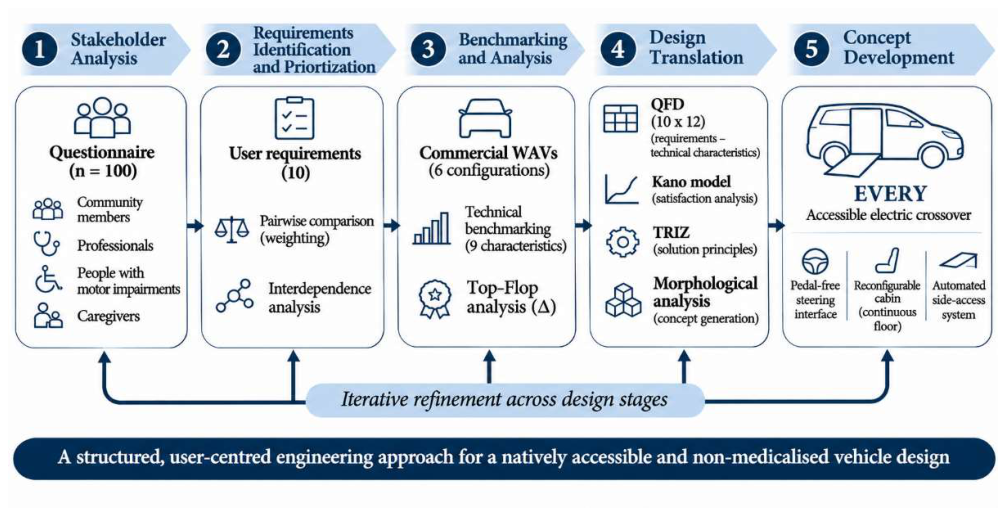
Figure 2.
Pedal-free steering interface. (a) Front view. (b) Side view of the steering column and the hub-fixed paddles. (c) Orthogonal projections (dimensions in mm; rim diameter 380 mm, column depth 315.5 mm). (d) Left cluster: display navigation, wipers and indicators, with the brake paddle (−). (e) Right cluster: audio, cruise-control and climate controls, with the throttle paddle (+). (f) Emergency-brake paddle on the right of the hub, which does not rotate with the rim.
Figure 2.
Pedal-free steering interface. (a) Front view. (b) Side view of the steering column and the hub-fixed paddles. (c) Orthogonal projections (dimensions in mm; rim diameter 380 mm, column depth 315.5 mm). (d) Left cluster: display navigation, wipers and indicators, with the brake paddle (−). (e) Right cluster: audio, cruise-control and climate controls, with the throttle paddle (+). (f) Emergency-brake paddle on the right of the hub, which does not rotate with the rim.
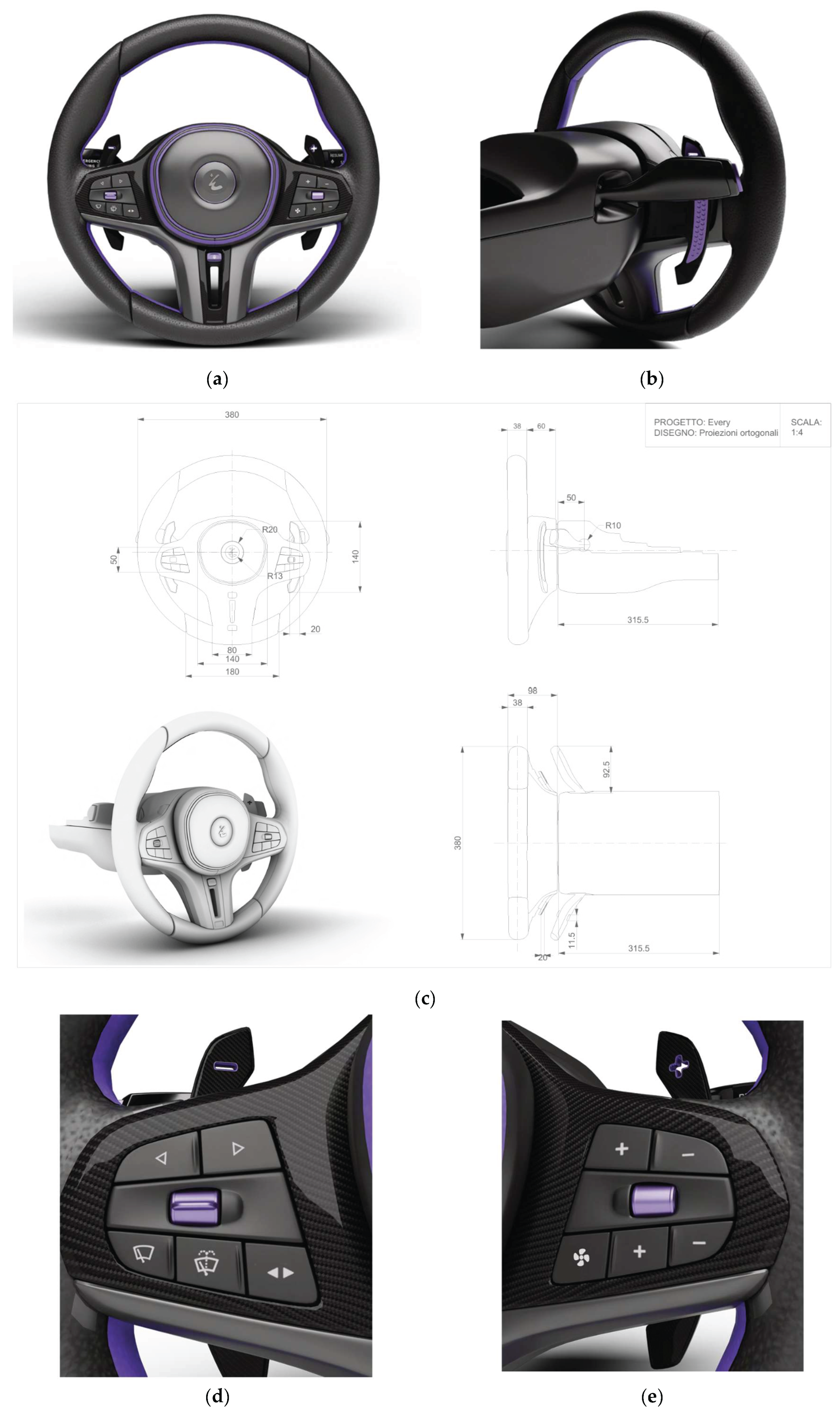
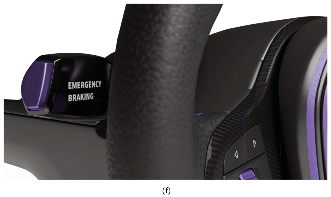
Figure 3.
Reconfigurable, tunnel-free cabin. (a) Interior with continuous floor between the front seats; (b, c) front seat with the integrated transfer board deployed and stowed; (d) dashboard with push-button drive selector; (e) design sketch of the layout, showing the Go/Reverse/parking-brake buttons and the absence of a central tunnel.
Figure 3.
Reconfigurable, tunnel-free cabin. (a) Interior with continuous floor between the front seats; (b, c) front seat with the integrated transfer board deployed and stowed; (d) dashboard with push-button drive selector; (e) design sketch of the layout, showing the Go/Reverse/parking-brake buttons and the absence of a central tunnel.
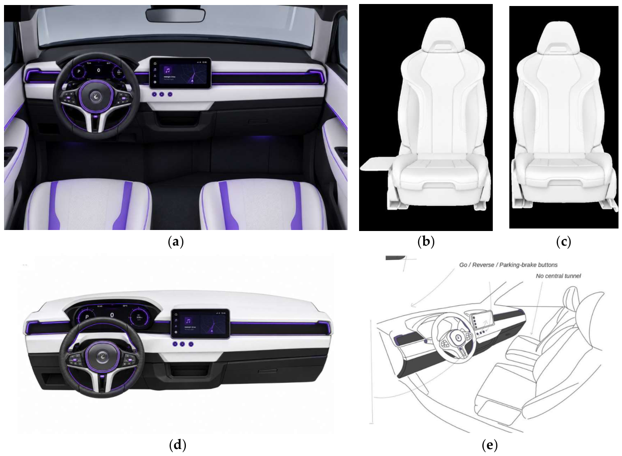
Figure 4.
Automated side-access system. (a-d) Sequence of operation: door opening and platform deployment, boarding at ground level, lifting, and inboard translation; (e, f) user on the platform at ground level, with the falcon-wing door open; (g) user secured in the travel position after inboard translation.
Figure 4.
Automated side-access system. (a-d) Sequence of operation: door opening and platform deployment, boarding at ground level, lifting, and inboard translation; (e, f) user on the platform at ground level, with the falcon-wing door open; (g) user secured in the travel position after inboard translation.
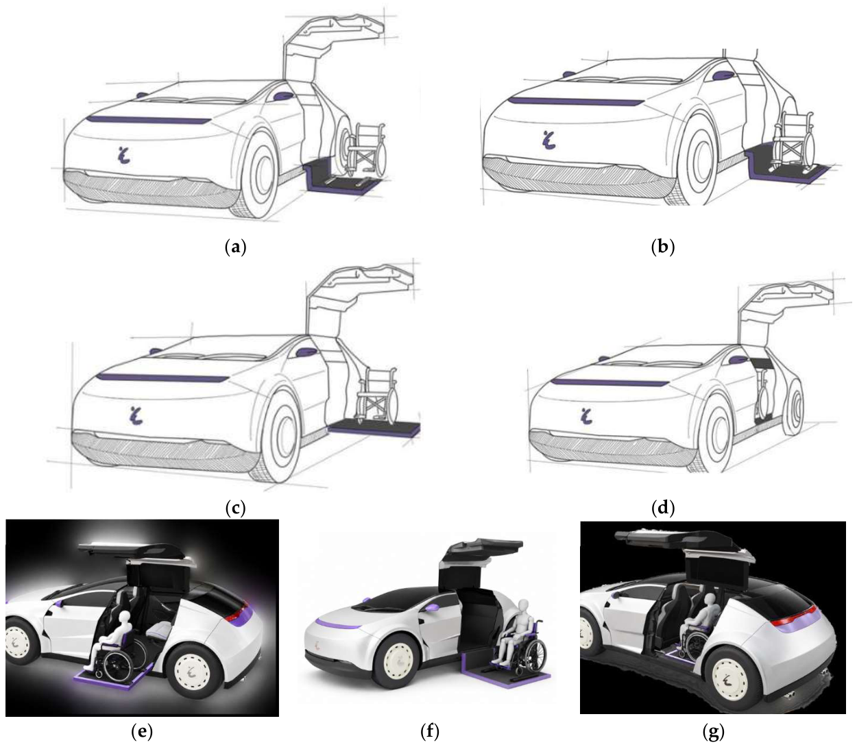
Figure 5.
Exterior concept. (a) Front view with doors closed and no visible accessibility device; (b) side view with the falcon-wing door open and the wheelchair stowed in the cabin.
Figure 5.
Exterior concept. (a) Front view with doors closed and no visible accessibility device; (b) side view with the falcon-wing door open and the wheelchair stowed in the cabin.
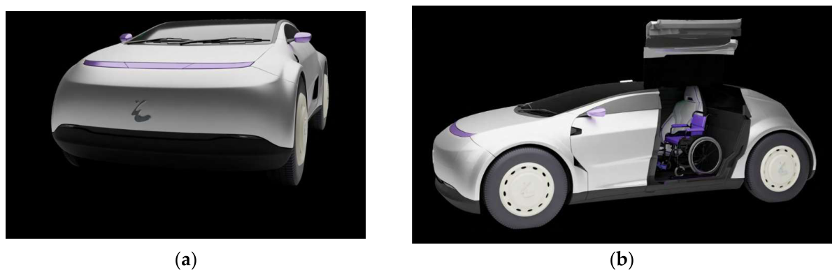

Table 1.
Stakeholder groups, sample sizes and questionnaire domains.
| Group (abbreviation) | n | Main topics surveyed |
|---|---|---|
| People with motor impairment (MI) |
30 | Current vehicles and controls; critical phases of car use; emotions; discomfort when requesting help; preferred appearance. |
| Caregivers (CG) | 20 | Most demanding assistance tasks; emotions during assistance; perceived condition of the assisted person; open suggestions. |
| Professionals (PRO) | 10 | Most problematic phases for assisted users; effect of dignified mobility on quality of life. |
| Community members (CM) |
40 | Perceived medicalization of adapted cars; acceptance of pedal removal and familiar control metaphors; purchase intention; attitudes to accessibility by design and automation. |
| Total | 100 |
Table 2.
Pairwise importance matrix and normalised requirement weights. Abbreviations: UA = Universal Accessibility; NMD = Non-medicalised Design; LRN = Learnability; ADP = Adaptability; MM = Multimodality; ERG = Ergonomic Comfort; EoA = Ease of Access; AUT = Operational Autonomy; TRU = Perceived Safety; FAM = Familiarity. Importance weights were calculated by normalising the row totals against the grand total (100).
Table 2.
Pairwise importance matrix and normalised requirement weights. Abbreviations: UA = Universal Accessibility; NMD = Non-medicalised Design; LRN = Learnability; ADP = Adaptability; MM = Multimodality; ERG = Ergonomic Comfort; EoA = Ease of Access; AUT = Operational Autonomy; TRU = Perceived Safety; FAM = Familiarity. Importance weights were calculated by normalising the row totals against the grand total (100).
| Requirement | UA | NMD | LRN | ADP | MM | ERG | EoA | AUT | TRU | FAM | Total | Weight (%) |
|---|---|---|---|---|---|---|---|---|---|---|---|---|
| UA | 1 | 2 | 1 | 1 | 2 | 1 | 1 | 1 | 1 | 1 | 12 | 12 |
| NMD | 0 | 1 | 1 | 1 | 1 | 1 | 1 | 1 | 2 | 2 | 11 | 11 |
| LRN | 1 | 1 | 1 | 1 | 1 | 1 | 1 | 1 | 2 | 1 | 11 | 11 |
| ADP | 1 | 1 | 1 | 1 | 2 | 1 | 1 | 1 | 2 | 1 | 12 | 12 |
| MM | 0 | 1 | 1 | 0 | 1 | 1 | 1 | 1 | 1 | 2 | 9 | 9 |
| ERG | 1 | 1 | 1 | 1 | 1 | 1 | 1 | 1 | 2 | 1 | 11 | 11 |
| EoA | 1 | 1 | 1 | 1 | 1 | 1 | 1 | 1 | 2 | 1 | 11 | 11 |
| AUT | 1 | 1 | 1 | 1 | 1 | 1 | 1 | 1 | 2 | 1 | 11 | 11 |
| TRU | 1 | 0 | 0 | 0 | 1 | 0 | 0 | 0 | 1 | 1 | 4 | 4 |
| FAM | 1 | 0 | 1 | 1 | 0 | 1 | 1 | 1 | 1 | 1 | 8 | 8 |
Table 3.
User requirement interdependence matrix. Scores: 0 = no relationship; 1 = weak; 3 = moderate; 9 = strong. The normalised interdependence index was calculated by dividing each column total by the maximum observed column total (43) and multiplying by 10. Abbreviations are defined in Table 2.
Table 3.
User requirement interdependence matrix. Scores: 0 = no relationship; 1 = weak; 3 = moderate; 9 = strong. The normalised interdependence index was calculated by dividing each column total by the maximum observed column total (43) and multiplying by 10. Abbreviations are defined in Table 2.
| Requirement | UA | NMD | LRN | ADP | MM | ERG | EoA | AUT | TRU | FAM |
|---|---|---|---|---|---|---|---|---|---|---|
| UA | 0 | 3 | 1 | 9 | 1 | 3 | 9 | 9 | 3 | 1 |
| NMD | 3 | 0 | 1 | 3 | 1 | 3 | 1 | 1 | 3 | 9 |
| LRN | 1 | 1 | 0 | 3 | 9 | 3 | 1 | 1 | 3 | 9 |
| ADP | 9 | 3 | 3 | 0 | 3 | 3 | 9 | 9 | 3 | 1 |
| MM | 1 | 1 | 9 | 3 | 0 | 3 | 1 | 1 | 3 | 9 |
| ERG | 3 | 3 | 3 | 3 | 3 | 0 | 9 | 3 | 9 | 3 |
| EoA | 9 | 1 | 1 | 9 | 1 | 9 | 0 | 9 | 3 | 1 |
| AUT | 9 | 1 | 1 | 9 | 1 | 3 | 9 | 0 | 3 | 1 |
| TRU | 3 | 3 | 3 | 3 | 3 | 9 | 3 | 3 | 0 | 3 |
| FAM | 1 | 9 | 9 | 1 | 9 | 3 | 1 | 1 | 3 | 0 |
| Column total | 39 | 25 | 31 | 43 | 31 | 39 | 43 | 37 | 33 | 37 |
| Normalised index | 9.07 | 5.81 | 7.21 | 10.00 | 7.21 | 9.07 | 10.00 | 8.60 | 7.67 | 8.60 |
Table 4.
Commercial wheelchair-accessible vehicle configurations selected for the comparative technical assessment. Different accessibility conversions of the same base vehicle were considered separate alternatives.
Table 4.
Commercial wheelchair-accessible vehicle configurations selected for the comparative technical assessment. Different accessibility conversions of the same base vehicle were considered separate alternatives.
| ID | Base vehicle | Conversion manufacturer | Accessibility configuration | Entry position | Model year |
|---|---|---|---|---|---|
| TOY-I | Toyota Sienna Hybrid | BraunAbility | Power Infloor | Side | 2026 |
| TOY-F | Toyota Sienna Hybrid | Power Foldout | |||
| HON | Honda Odyssey | Power Infloor | |||
| CHE | Chevrolet Traverse | XI Power Infloor | |||
| FOR | Ford Tourneo Custom | Allied Mobility | Independence | Rear | Current documented configuration |
| PEU | Peugeot Rifter | Horizon |
Table 5.
Verified technical benchmarking and Top-Flop analysis. TOY-I = Sienna Infloor; TOY-F = Sienna Foldout; HON = Odyssey; CHE = Traverse; FOR = Tourneo Independence; PEU = Rifter Horizon.
Table 5.
Verified technical benchmarking and Top-Flop analysis. TOY-I = Sienna Infloor; TOY-F = Sienna Foldout; HON = Odyssey; CHE = Traverse; FOR = Tourneo Independence; PEU = Rifter Horizon.
| Technical characteristic | TOY-I | TOY-F | HON | CHE | FOR | PEU |
|---|---|---|---|---|---|---|
| Ramp clear width (mm) ↑ | 770 | 743 | 775 | 775 | 810 | 830 |
| Ramp length (mm) ↓ | 1321 | 1321 | 1321 | 1321 | 1245 | 1248 |
| Nominal ramp angle (°) ↓ | 9.5 | 9.0 | 9.2 | 10.0 | 12.9 | 15.45 |
| Declared entrance height (mm) ↑ | 1372 | 1422 | 1384 | 1384 | 1525 | 1354 |
| Ramp rated load (kg) ↑ | 454 | 454 | 454 | 454 | 400 | 400 |
| Clear entrance width (mm) ↑ | 787 | 787 | 775 | 775 | 800 | 820 |
| Overall vehicle height (mm) ↓ | 1981 | 1981 | 1905 | 1892 | 1981 | 1880 |
| Overall vehicle length (mm) ↓ | 5175 | 5175 | 5212 | 5194 | 5050 | 4753 |
| Overall vehicle width (mm) ↓ | 1994 | 1994 | 1994 | 2022 | 2032 | 1848 |
| TOP | 1 | 2 | 1 | 1 | 2 | 5 |
| FLOP | 2 | 3 | 3 | 2 | 3 | 3 |
| Delta (∆) | -1 | -1 | -2 | -1 | -1 | +2 |
Table 6.
Weighted What/How matrix and technical characteristic prioritisation.
| Requirement | VT | THR | TIME | CONF | ANCH | HAND | TSEAT | TUN | RAMP | PED | OPS | HC |
|---|---|---|---|---|---|---|---|---|---|---|---|---|
| UA | 8 | 10 | 8 | 8 | 4 | 8 | 8 | 10 | 10 | 4 | 6 | 10 |
| NMD | 10 | 2 | 6 | 2 | 4 | 0 | 2 | 2 | 10 | 0 | 0 | 2 |
| LRN | 0 | 0 | 0 | 2 | 0 | 0 | 0 | 0 | 0 | 0 | 2 | 8 |
| ADP | 4 | 2 | 2 | 10 | 2 | 4 | 8 | 4 | 6 | 8 | 2 | 6 |
| MM | 0 | 0 | 0 | 2 | 0 | 0 | 0 | 0 | 0 | 0 | 2 | 2 |
| ERG | 8 | 6 | 6 | 8 | 4 | 8 | 10 | 10 | 4 | 10 | 2 | 10 |
| EoA | 8 | 10 | 10 | 4 | 4 | 8 | 8 | 10 | 10 | 2 | 4 | 0 |
| AUT | 2 | 6 | 8 | 8 | 6 | 6 | 6 | 6 | 6 | 8 | 10 | 10 |
| TRU | 2 | 4 | 4 | 4 | 10 | 8 | 2 | 2 | 6 | 6 | 6 | 2 |
| FAM | 6 | 2 | 0 | 2 | 0 | 2 | 2 | 2 | 2 | 2 | 4 | 8 |
| Weighted score | 5.08 | 4.40 | 4.66 | 5.30 | 3.10 | 4.34 | 5.02 | 5.00 | 5.62 | 4.04 | 3.68 | 6.12 |
| Normalised score | 8.3 | 7.19 | 7.61 | 8.66 | 5.07 | 7.09 | 8.2 | 8.17 | 9.18 | 6.6 | 6.01 | 10 |
| Rank | 4 | 8 | 7 | 3 | 12 | 9 | 5 | 6 | 2 | 10 | 11 | 1 |
Table 7.
Kano-based interpretation of the three priority technical characteristics. Categories reflect the design assessment informed by the stakeholder questionnaire.
Table 7.
Kano-based interpretation of the three priority technical characteristics. Categories reflect the design assessment informed by the stakeholder questionnaire.
| Technical characteristic | Kano category | Design interpretation | EVERY response |
|---|---|---|---|
| Steering-wheel hand controls | Attractive | Integrated manual controls enhance driving autonomy and provide an interaction model associated with familiar automotive and gaming interfaces. | Pedal-free steering wheel with integrated acceleration, braking and secondary controls |
| Number of interior configurations | Attractive | Cabin reconfigurability supports different seating arrangements, individual mobility requirements and transfer needs. | Tunnel-free cabin, modular anchorage and integrated transfer board |
| Access ramp type | One-dimensional | Boarding accessibility depends on entry geometry, operational effort and the independence afforded by the access mechanism. | Automated side-access platform incorporating lifting and inward translation |
Table 8.
Technical contradictions, selected TRIZ inventive principles and their application to EVERY concept. The contradictions originate from the design study, while the retained principles identify the solutions developed in the final architecture.
Table 8.
Technical contradictions, selected TRIZ inventive principles and their application to EVERY concept. The contradictions originate from the design study, while the retained principles identify the solutions developed in the final architecture.
| Design characteristic | TRIZ contradiction (improving / worsening) | Retained inventive principles | Applications in EVERY |
|---|---|---|---|
| Steering-wheel hand controls | 33 - Ease of operation / 36 - Device complexity; 35 - Adaptability / 36 - Device complexity. | 26 - Copying | Familiar control arrangements inspired by sim-racing interfaces, with acceleration and braking integrated into the steering assembly. |
| Interior configurations | 35 - Adaptability / 7 - Volume of moving object; 35 - Adaptability / 36 - Device complexity. | 15 - Dynamics; 28 - Mechanics substitution | Reconfigurable cabin architecture with a continuous floor, modular anchorage provisions and adaptable interfaces. |
| Access-system type | 7 - Volume of moving object / 33 - Ease of operation; 12 - Shape / 33 - Ease of operation | 15 - Dynamics; 34 - Discarding and recovering. | Concealed access mechanism integrated into the vehicle sill, incorporating deployment, lifting and inward translation. |
Table 9.
Morphological matrix of the technical alternatives investigated during concept development and the features incorporated into EVERY.
Table 9.
Morphological matrix of the technical alternatives investigated during concept development and the features incorporated into EVERY.
| Subsystem | Solution 1 | Solution 2 | Solution 3 | Solution 4 | Selected design features |
|---|---|---|---|---|---|
| Steering-wheel hand controls | Sim-racing-inspired acceleration and braking | Coaxial arrangement of controls | Pneumatic soft-actuation and haptic feedback | - | Sim-racing-inspired manual controls integrated into the steering assembly |
| Interior configurations | Central tunnel elimination | Universal floor anchorage | Reconfigurable human-machine interface | Integrated transfer board | Tunnel-free floor, modular anchorage and integrated transfer board |
| Access system | Segmented folding ramp | Length-adjustable ramp | Access mechanism integrated into vehicle sill | Visually concealed access mechanism | Concealed sill-integrated access platform with automated movement |
Table 10.
Main engineering characteristics and preliminary specifications of EVERY concept. The design basis identifies geometric specifications, architectural decisions, functional arrangements and preliminary engineering targets.
Table 10.
Main engineering characteristics and preliminary specifications of EVERY concept. The design basis identifies geometric specifications, architectural decisions, functional arrangements and preliminary engineering targets.
| Subsystem | Technical characteristic | Proposed specification | Verification status |
|---|---|---|---|
| Vehicle architecture | Vehicle configuration | Mid-size electric crossover | Concept architecture |
| Overall length | Approximately 4,970 mm | Preliminary CAD | |
| Wheelbase | Approximately 3,000 mm | Preliminary CAD | |
| Nominal floor height | Approximately 300 mm | Design assumption | |
| Steering interface |
Steering-wheel geometry | D-shaped, 380 mm nominal diameter | CAD geometry |
| Primary driving controls | Rear-mounted throttle and brake paddles | Functional layout | |
| Secondary controls | Two thumb-operated clusters | Functional layout | |
| Hub-fixed controls | Cruise control and emergency braking | Functional layout | |
| Steering range | Approx. 720° lock-to-lock | Design assumption | |
| Foot pedals | Eliminated | Architectural choice | |
| Cabin | Central tunnel | Eliminated | Architectural choice |
| Transmission selection | Dashboard-mounted push buttons | Functional layout | |
| Transfer assistance | Hinged, folding transfer board | CAD geometry | |
| Seating architecture | Reconfigurable, modular anchorage concept | Concept architecture | |
| Transfer board stowed thickness | Below 20 mm | Preliminary design | |
| Additional transfer support | Removable support arm and grab handles | Functional layout | |
| Access system | Entry configuration | Lateral | Architectural choice |
| Door mechanism | Roof-hinged falcon-wing door | CAD geometry | |
| Platform configuration | Sill-integrated, automated | Concept architecture | |
| Platform movement | Deployment, lifting and inward translation | Functional concept | |
| Preliminary clear platform width | 1,000 mm | Preliminary design | |
| Preliminary clear platform length | 1,000 mm | Preliminary design | |
| Platform design load | 300 kg | Design target |
Disclaimer/Publisher’s Note: The statements, opinions and data contained in all publications are solely those of the individual author(s) and contributor(s) and not of MDPI and/or the editor(s). MDPI and/or the editor(s) disclaim responsibility for any injury to people or property resulting from any ideas, methods, instructions or products referred to in the content. |
© 2026 by the authors. Licensee MDPI, Basel, Switzerland. This article is an open access article distributed under the terms and conditions of the Creative Commons Attribution (CC BY) license (http://creativecommons.org/licenses/by/4.0/).
Copyright: This open access article is published under a Creative Commons CC BY 4.0 license, which permit the free download, distribution, and reuse, provided that the author and preprint are cited in any reuse.