

Submitted:
13 November 2026
Posted:
16 November 2026
You are already at the latest version
Abstract
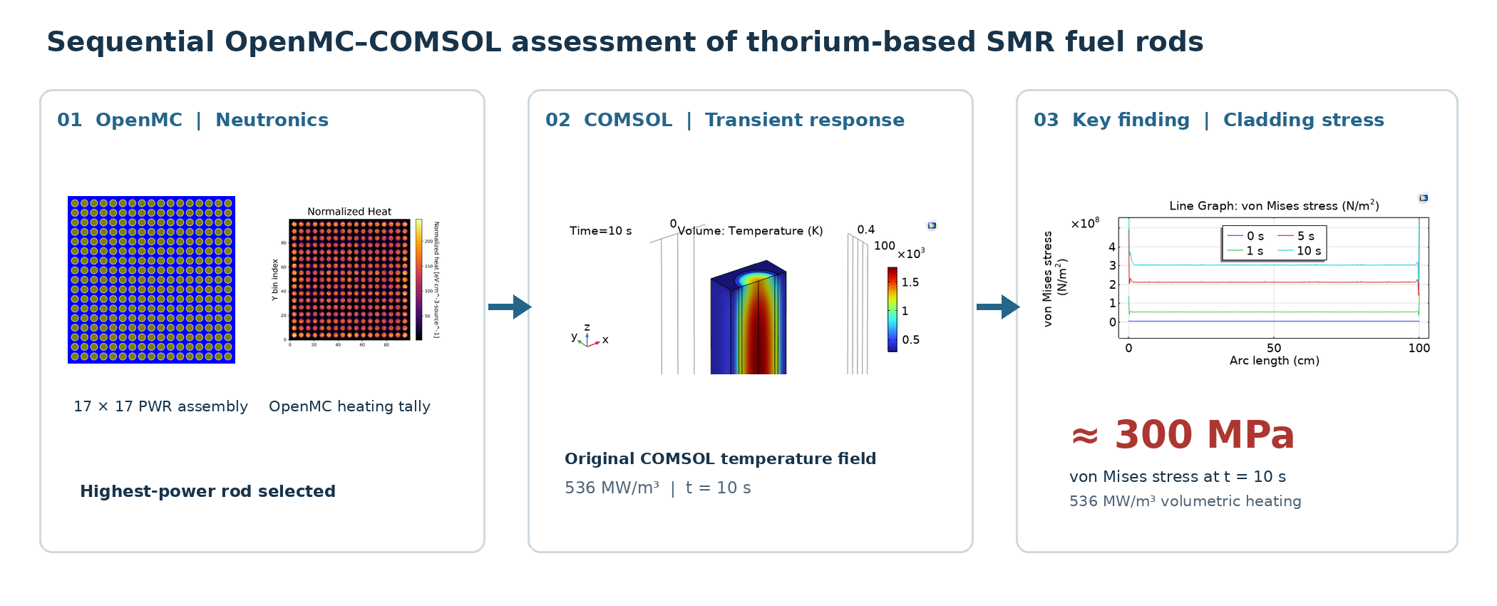
The growing interest in small modular reactors (SMRs) has created a demand for computational methodologies capable of assessing reactor performance and safety-related behavior during the early stages of design. In this study, reactor thermal-power conditions of 60, 90, and 120 MWth were selected to investigate power-dependent thermal-hydraulic and thermomechanical responses of a thorium-based pressurized water reactor (PWR) fuel rod within a range relevant to low-power SMR concepts. Increasing heat generation and heating time resulted in progressively higher fuel temperatures and stronger mechanical responses. At 536 MW m⁻³ heat flux, the calculated fuel temperature after 10 s exceeded the 1400 °C temperature criterion adopted in the computational assessment. The coolant velocity remained approximately 0.9–1.0 m s⁻¹ over most of the modeled channel. The maximum reported cladding displacement reached approximately 2.2*10-4 m, while the von Mises stress at 10 s increased from approximately 210 MPa at 268 MW m⁻³ to 300 MPa at 536 MW m⁻³. By integrating OpenMC neutron-transport calculations with transient COMSOL Multiphysics simulations, the proposed sequential coupling methodology provides a means of evaluating how fuel driven heat flux influences local heat generation, fuel and clad temperature, coolant behavior, and structural loading. Such an approach could support the preliminary development and comparative evaluation of thorium-fueled SMR configurations, particularly by identifying highly loaded fuel rods and potentially demanding operating conditions before detailed engineering design and experimental validation.
Keywords:
thorium-based fuel
; pressurized water reactor
; fuel rod
; OpenMC
; COMSOL multiphysics
; transient analysis
; thermal–mechanical response
1. Introduction
The development of advanced nuclear reactor technologies has received increasing attention as part of global efforts to improve energy security, reduce greenhouse gas emissions, and provide reliable low-carbon electricity generation. Among the emerging nuclear energy technologies, small modular reactors SMRs have attracted considerable interest because of their relatively compact configurations, modular construction concepts, and potential applications in decentralized electricity generation, industrial heat production, and remote energy systems [1]. The International Atomic Energy Agency (IAEA) generally categorizes SMRs as reactors with an electrical generation capacity of up to 300 MWe per module. Nevertheless, the successful development and deployment of advanced reactor systems require comprehensive investigations of reactor neutronics, heat transfer, coolant behavior, and structural integrity under different operating conditions. These processes are strongly interconnected, making integrated multiphysics computational approaches particularly relevant to preliminary reactor design, performance optimization, and safety-oriented assessment.
In parallel with advancements in reactor technology, thorium-based nuclear fuels have attracted renewed scientific interest as potential alternatives or supplements to conventional uranium-based fuel cycles. Naturally occurring thorium consists predominantly of fertile ²³²Th, which can be converted into fissile ²³³U through neutron absorption and subsequent radioactive decay. Thorium-containing fuels offer potential advantages associated with resource availability, fuel-cycle flexibility, and the thermophysical and chemical characteristics of thorium dioxide (ThO₂) [2]. However, the practical utilization of thorium-based fuels presents significant technological challenges, including fuel fabrication, irradiation behavior, fuel-cycle implementation, and spent-fuel management. Consequently, the assessment of thorium fuel performance requires consideration of both its neutronic behavior and the thermal and mechanical conditions experienced during reactor operation.
The implementation of thorium-based fuels in pressurized water reactors (PWRs) is particularly relevant because water-cooled reactor technology has a well-established engineering and operational background. Thorium–uranium oxide fuel mixtures have been investigated as potential fuel compositions for improving fuel-cycle flexibility while maintaining compatibility with selected features of existing reactor technologies. Nevertheless, replacing conventional uranium oxide with thorium-containing fuel can influence neutron multiplication, neutron-energy spectra, spatial power distributions, and temperature-dependent fuel behavior. These changes may affect the temperature distribution within fuel rods, heat transfer to the surrounding coolant, and thermally induced deformation of the fuel and cladding. Therefore, neutronic feasibility alone is insufficient to characterize the performance of thorium-based PWR fuel systems.
Recent developments in computational reactor physics have enabled increasingly detailed investigations of such interconnected phenomena. Monte Carlo neutron-transport methods are widely employed to characterize reactor criticality, neutron-flux distributions, energy deposition, and spatially varying heat generation. Romano et al. [3] described OpenMC as a continuous-energy Monte Carlo particle-transport code designed for high-fidelity nuclear reactor analysis. Its geometry modeling and tally capabilities enable detailed calculations of neutron transport and power distributions in complex reactor configurations. However, neutron-transport simulations alone do not directly provide the transient temperature, coolant-flow, or mechanical stress fields needed to evaluate the response of reactor components during operation. These quantities require the integration of neutronic results with thermal-hydraulic and structural mechanics models. The importance of multiphysics analysis for nuclear fuel performance was demonstrated by Williamson et al. [4], who developed a multidimensional computational approach for analyzing the coupled thermal and mechanical behavior of nuclear fuel using the BISON framework. Their work highlighted the complexity of fuel-performance phenomena, including heat conduction, deformation, fuel–cladding interaction, and temperature-dependent material behavior. Subsequent developments in finite-element-based fuel-performance modeling have further demonstrated the importance of accounting for thermomechanical interactions when evaluating fuel integrity. Such investigations establish that reactor fuel behavior cannot always be represented adequately by independent thermal or mechanical calculations, particularly when material response, contact conditions, and temperature fields evolve simultaneously. The integration of Monte Carlo neutron transport with multiphysics computational environments has also been investigated. Ellis et al. [5] explored the coupling of OpenMC with the Multiphysics Object-Oriented Simulation Environment (MOOSE) to investigate temperature-dependent neutronic feedback. This approach demonstrated the potential of combining detailed neutron-transport calculations with multiphysics solvers to represent interactions between neutron behavior and thermal fields. More recently, reviews of Monte Carlo-based multiphysics modeling have emphasized the growing importance of coupled neutronic, thermal-hydraulic, and mechanical simulations for advanced nuclear reactor analysis [6,7]. Such frameworks can improve the physical consistency of reactor simulations by relating neutron-induced energy deposition to local temperature distributions and subsequent structural responses. Recent studies have demonstrated the continued development of coupled computational methods for both conventional and advanced reactor systems using OpenMC–COMSOL-based multiphysics approach [8,9]. Nie et al. [10] developed an OpenMC–COMSOL-based neutronic–thermal methodology for heat-pipe-cooled microreactors, using Monte Carlo-generated neutronic information and a finite-element multiphysics framework to investigate thermal feedback and reactor transients. Their results demonstrated the applicability of integrated computational tools to the analysis and optimization of compact reactor concepts. Similarly, a partitioned coupling framework combining OpenMC and OpenFOAM has been developed and examined using fuel-rod and fuel-assembly configurations, including a 17 × 17 assembly [11]. These investigations demonstrate growing interest in transferring physically consistent information between neutronic and thermal-hydraulic models and highlight the potential of multiphysics methods for advanced reactor development. In another relevant investigation, Refaey et al. [12] studied the thermal and mechanical behavior of thorium–uranium and thorium–plutonium fuel systems in a PWR using coupled MCNP6 and ANSYS simulations. Their computational approach incorporated neutron-transport, thermal-hydraulic, and structural analyses under steady-state conditions. The study demonstrated how fuel composition and the resulting thermal behavior influence mechanical loading within the fuel–cladding system. In particular, the comparison of different thorium-containing fuel compositions highlighted the importance of integrating reactor-physics calculations with thermal and mechanical modeling when evaluating potential fuel alternatives.
In this study, reactor thermal power levels of 60, 90, and 120 MWth were considered to assess the influence of power variation on the thermal-hydraulic and thermomechanical behavior of a thorium-based pressurized water reactor (PWR) fuel rod. The results demonstrated that increasing volumetric heat generation and heating duration led to higher fuel temperatures and more pronounced mechanical responses. At a volumetric heat generation rate of 536 MW m⁻³, the predicted fuel temperature exceeded the 1400 °C threshold adopted in the numerical assessment after 10 s of heating. Meanwhile, the coolant velocity remained relatively stable, ranging from approximately 0.9 to 1.0 m s⁻¹ throughout most of the modeled channel. The maximum cladding displacement was approximately 2.2 × 10⁻⁴ m, whereas the von Mises stress at 10 s increased from approximately 210 MPa at 268 MW m⁻³ to 300 MPa at 536 MW m⁻³. The sequential coupling of OpenMC neutron transport calculations with transient COMSOL Multiphysics simulations enabled a comprehensive assessment of the relationships between reactor power, spatial heat generation, fuel and cladding temperatures, coolant flow characteristics, and mechanical stresses. The computational framework offers a useful tool for the preliminary design and comparative assessment of thorium-fueled SMR systems, allowing the identification of fuel rods subjected to elevated thermal and mechanical loads and potentially critical operating conditions prior to detailed engineering optimization and experimental validation.
2. Materials and Methods
2.1. Computational Framework
A sequential computational framework was used to connect reactor-level neutron-transport calculations with the transient thermal and mechanical response of an individual fuel rod. The analysis consisted of two principal stages. First, the neutronic characteristics and spatial power distribution of the thorium-based PWR fuel assembly were calculated using the OpenMC Monte Carlo particle-transport code. The resulting spatial power distribution was then used to identify the fuel rod subjected to the highest local heat generation.
In the second stage, the selected fuel rod was analyzed using COMSOL Multiphysics. Local volumetric heat-generation rates corresponding to reactor thermal powers of 60, 90, and 120 MWth were applied as internal heat sources in the transient model. Thermal-hydraulic and mechanical responses were evaluated at 1, 5, and 10 s. The calculated quantities included fuel temperature, coolant velocity, cladding volumetric deformation, displacement, and von Mises stress.
The coupling between the two computational stages was sequential: the OpenMC-derived power distribution provided the thermal-loading input for the subsequent COMSOL calculations.
2.2. PWR Fuel-Assembly Model
The neutronic model represented a square 17 × 17 PWR fuel assembly containing thorium-based oxide fuel. The fuel material was specified as (Th,^233U)O₂, Zircaloy-4 was used as the cladding material, and light water (H₂O) served as both moderator and coolant. The fuel-pellet diameter was 1 cm, the cladding thickness was 0.2 cm, and the modeled fuel-element height was 100 cm. The principal geometrical and material parameters of the model are summarized in Table 1.
The top and side views of the modeled PWR fuel assembly are shown in Figure 1.
2.3. OpenMC Neutron-Transport Model
Neutron-transport calculations were performed using the OpenMC Monte Carlo particle-transport code in (k)-eigenvalue mode (OpenMC version: 0.15.2, Data library: ENDF-B.VII.0-HDF5). The model materials were defined by their constituent nuclides or elements, densities, compositions, and temperatures, and the reactor geometry was constructed using constructive solid geometry. Neutron flux and heating were specified as tally quantities.
In the (k)-eigenvalue calculation, source particles were propagated through successive generations. Because the converged fission-source distribution is not known a priori, initial generations were used to establish source convergence before tally statistics were accumulated. The OpenMC calculations provided the effective multiplication factor, neutron-energy spectrum, neutron flux, and spatial heating distribution used in the subsequent analysis. 240 number of batches, 120 number of inactive batches, 96000 number of particles per batch and 1 number of generations per batch of k-eigenvalue calculation settings were used. Mesh dimension was 100*100*100. Energy dimension was 500-group (from 10^-5 eV to 20.0e+6 eV) and known data library SHEM-361 energy-group structure was used for comparison of the energy-dependent neutron distribution.
2.4. Power Normalization
The OpenMC tally results were normalized to the prescribed reactor thermal powers of 60, 90, and 120 MWth to obtain physically scaled neutron-flux and heat-generation quantities. The heating tally provided the energy deposition per source particle, (H), in units of eV/source. The calculated heating was first converted from eV/source to J/source according to Equation (1).
where (H) is the heating value obtained from the OpenMC calculation.
The normalization factor corresponding to the prescribed reactor thermal power, (P), was subsequently obtained by dividing the reactor power by the calculated heating per source particle:
The resulting normalization factor was then applied to the calculated tally quantities. For the neutron flux, the tally result was multiplied by the normalization factor and normalized by the corresponding tally volume:
where denotes the normalized neutron flux and (V) is the volume over which the tally was evaluated. This procedure provided the power-normalized neutron-flux and heat-generation distributions used to identify the fuel rod subjected to the highest local thermal loading and to define the heat-source conditions for the subsequent transient analysis.
The power-normalized spatial heat-generation distribution obtained from the OpenMC calculation was used to identify the fuel rod subjected to the highest local thermal loading within the modeled assembly. This rod was selected for the subsequent transient thermal-hydraulic and mechanical analysis in COMSOL Multiphysics, thereby providing a direct link between the reactor-level neutron-transport calculation and the fuel-rod-scale multiphysics model.
Three reactor thermal-power conditions were considered. The corresponding local volumetric heat-generation rates applied to the selected fuel rod are summarized in Table 2.
These three heat-generation conditions were subsequently used to evaluate the effect of increasing reactor power on the transient thermal and mechanical response of the selected fuel rod.
2.5. Heat Transfer in Solids
Thermal-hydraulic and solid-mechanics calculations can be performed using the radial power distribution obtained from the neutronic analysis. The heat-generation PDE was solved using the finite element method (FEM). Because thermal power was applied across the cross-sectional surface of the core, the transient Fourier heat conduction equation was used to determine the both spatial and transient temperature distribution. The PDE was discretized over the computational mesh, and its solution yielded the temperature profiles in the fuel, cladding, and coolant. All boundaries, except the top, bottom, and cross-sectional surfaces, were assumed to be thermally insulated.
For the thermal properties of fuel [13] and clad materials [14] the following expressions were used:
Specific heat capacity of (Th, 233U)O2:
Thermal conductivity of (Th, 233U)O2:
Density of (Th, 233U)O2:
Specific heat capacity of zircalloy-4:
Cp = 238 + 0.159T [J/kg K]
Thermal conductivity of zircalloy-4:
Density of zircalloy-4:
ρ = 6650 − 0.286T [kg/m3]
2.5. Fluid Dynamics
The Navier–Stokes equations for momentum and mass conservation were solved to obtain the coolant pressure drop along the axial (z) direction and the corresponding velocity field. When the turbulent-flow (k–ω) model is coupled with the heat-transfer physics, two important outputs are obtained: (1) the convective heat-transfer coefficient, h, which depends on the coolant velocity, channel geometry, and the temperature-dependent properties of the coolant, and (2) the axial pressure drop predicted by the Navier–Stokes solution. By combining this pressure drop with the temperature distribution and local heat flux obtained from the heat-generation equation, the coolant’s proximity to nucleate boiling can be evaluated at any position along the z-axis. The top and bottom surfaces were defined as the water inlet and outlet boundaries, respectively.
2.7. Solid Mechanics
Within the solid-mechanics interface, the governing elasticity equations were solved to evaluate thermally induced deformation, displacement magnitude, and strain in the fuel and cladding, fully coupled with the heat-transfer physics. The top and bottom boundaries were fixed to represent the physical constraints imposed by the reactor support structure.
For mechanical properties, the following thermal expansion expressions for fuel [15] and clad [13] were used:
Young’s Modulus expressions for fuel and clad materials [30]:
The effects of burn-up, plutonium content, pellet cracking, swelling, oxygen-to-metal ratio, and gaseous fission product release on the fuel’s thermal properties were not considered. It is well established that particle irradiation can significantly influence the mechanical and structural properties of materials [16,17]. However, irradiation-induced effects are not considered in the present study due to the limited availability of relevant literature data.
3. Results and Discussion
3.1. Neutronic Characteristics and Power-Dependent Thermal Loading
The OpenMC calculation yielded an effective multiplication factor of
for the modeled thorium-based PWR fuel assembly. The calculated neutron-energy spectrum is shown in Figure 2.
k_eff = 1.04285 ± 0.00020
The calculated spectrum provides the energy-dependent neutron distribution corresponding to the modeled fuel composition and assembly configuration. A more detailed quantitative interpretation of the spectral characteristics is not attempted here because the principal role of the OpenMC calculation in the present study is to establish the spatial power distribution used as the thermal-loading basis for the subsequent transient fuel-rod analysis.
The power-normalized neutron-flux and heat-generation distributions are shown in Figure 3. The transverse distributions reveal spatial variation within the modeled assembly and provide the basis for identifying the fuel rod subjected to the highest local thermal loading.
The OpenMC-derived power distribution was subsequently used to connect the prescribed reactor thermal power to the local heat-generation conditions imposed in the transient COMSOL model. Reactor thermal powers of 60, 90, and 120 MWth corresponded to local volumetric heat-generation rates of 268, 402, and 536 MW m⁻³, respectively, for the selected highest-power fuel rod. Thus, increasing reactor thermal power from 60 to 120 MWth doubled the local volumetric heat-generation rate applied in the transient analysis.
This reactor-to-local-power mapping is central to the present computational framework. Rather than assigning independent heat-source values directly to the fuel-rod model, the transient thermal and mechanical calculations were based on the local thermal loading derived from the preceding neutron-transport calculation. This establishes a sequential relationship between reactor-level power, the spatial distribution of neutron-induced heating, and the subsequent fuel-rod response.
The calculated neutronic behavior is consistent with the role of Monte Carlo neutron-transport analysis in resolving spatial power distributions in thorium-containing reactor systems [8]. In the previous thorium-based PWR study by Aryngazin et al. [8], OpenMC calculations were likewise used to characterize the effective multiplication factor and spatial power distribution before thermal-hydraulic and mechanical analysis. The present work extends this computational sequence by focusing specifically on the highest-power fuel rod and following its response under three systematically increasing power conditions over a 10 s transient interval.
3.2. Thermal-Hydraulics
To maintain safe reactor operation, the fuel centerline temperature must stay below the fuel melting point, and the average fuel temperature must remain below 1400 °C [18]. The spatial temperature distributions obtained after applying 268 MW/m3, 402 MW/m3 and 536 MW/m3 heat sources for different times (at 1s, 5s and 10 s) are presented in Figure 4, (a), (b) and (c), respectively. As heat propagates from the inner region of the fuel toward the outer surface, the temperature profile follows a parabolic trend. The temperature profile in 3D at maximum heat source (536 MW/m3) after 10s heating is shown in Figure 3(d). The fuel centerline temperature at this maximum heat source exceeds the maximum allowable temperature for safe reactor operation. Moreover, the results indicate that longer heat-source exposure leads to higher core temperatures than shorter exposure periods. A comparable temporal increase in the temperatures of the fuel and cladding was also observed in a coupled neutronic, thermo-elastic, and fluid-dynamic transient model for single-channel analysis of a Lead Fast Reactor [19].
The coolant velocity distribution in the reactor core at different heating times is shown in Figure 5. The velocity remains nearly stable along most of the channel length, with values close to 0.9–1.0 m/s, but increases near the outlet region, especially at longer times as can be seen from Figure 3a. The three-dimensional velocity magnitude profile after 10 s of heating at a heat source of 536 MW/m³ is provided in Figure 5, (b). The color distribution indicates that the coolant velocity remains relatively uniform and mostly high within the channel, with values around 1 m/s. Overall, the figure suggests that the coolant flow remains stable during heating, with only a localized increase in velocity near the outlet.
3.2. Solid Mechanics
The volumetric strain along the height of clad material at 0, 1, 5, and 10 s for three different heat-source values: 268, 402, and 536 MW/m³ is provided in Figure 6. In all cases, the strain is nearly zero at 0 s and increases with heating time. After a sharp rise near the inlet region, the volumetric strain remains almost constant along most of the core height, indicating a relatively uniform deformation response. Overall, the volumetric strain increases with both heating time and heat-source values, as can be seen from Figure 6, (a), (b), (c), while remaining nearly uniform along the reactor core height after the initial entrance region. However, the corresponding volumetric strain values are higher for Zircaloy-4 cladding materials. Therefore, further detailed research should be conducted.
Figure 7 shows the displacement magnitude along the height of clad material at 0, 1, 5, and 10 s for three different volumetric heat sources: 268, 402, and 536 MW/m³. In all three cases, the displacement is nearly zero at the initial time and increases as heating progresses, indicating progressive thermal expansion of the material. At the lowest heat source in Figure 7, (a), 268 MW/m³, the maximum displacement reaches approximately 8–9×m after 5–10 s. When the heat source is increased to 402 MW/m³, the peak displacement rises to about 1.2× m³, as can be seen from Figure 7, (b). The highest heat source, 536 MW/m³, produces the largest displacement, reaching approximately 2.2×m, as it’s derived from Figure 7, (c). This trend confirms that thermal deformation becomes stronger as the internal heat generation increases. At 1 s, the displacement remains relatively small for all heat-source values, while at 5 and 10 s the displacement increases significantly. In some regions, the 5 s curve is slightly higher than the 10 s curve, which may indicate redistribution of thermal stresses, boundary-condition effects, or transient mechanical relaxation during heating. Since the displacement is evaluated along the cladding height, the maximum displacement of approximately 2.2×m corresponds to a small axial strain of about 2.2×m, or 0.022%, over a 1 m core height. This indicates that the axial deformation of the Zircaloy-4 cladding remains limited. However, the volumetric strain reaches approximately 0.019 at the highest heat source, corresponding to an equivalent linear strain of about 0.63%. This value is considerably larger than the displacement-based axial strain. Overall, the displacement response is acceptable, whereas the volumetric strain is higher for confirming safe cladding operation [20].
Figure 8 presents the von Mises stress distribution along the radial distance at 0, 1, 5, and 10 s for three different heat-source values: 268, 402, and 536 MW/m³. In all three cases, the stress is nearly zero at the initial time and increases with heating time, showing that thermal loading produces progressively stronger mechanical stresses. At 268 MW/m³ in Figure 8, (a), the stress increases from a low value at 1 s to approximately 1.3×10⁸ N/m2 at 5s and about 2.1×10⁸ N/m2 at 10 s. At 402 MW/m³ in Figure 8, (b), the stress becomes higher, reaching roughly 1.7×10⁸ N/m2 at 5 s and about 2.7×10⁸ N/m2 at 10 s. The highest heat source, 536 MW/m³ in Figure 8, (c), gives the largest stress response, with values around 2.1×10⁸ N/m2 at 5 s and approximately 3.0×10⁸ N/m2 at 10 s. Overall, von Mises stress increases with both heating time and heat-source intensity. This behavior is expected because higher heat generation produces larger temperature gradients and stronger thermal expansion, which increase thermal stress. These values are below the room-temperature strength of Zircaloy-type cladding. However, since Zircaloy strength decreases significantly with temperature, the highest calculated stresses exceed the allowable stress limit under elevated-temperature operating conditions [21].
4. Conclusions
In conclusion, a sophisticated neutronics analysis provided good insight on the criticality of an assembly with convenient uranium fuel replaced by newly considered thorium, as well as obtained neutron flux and distribution of an assembly, and heat distribution of each channel of an assembly. The coupled thermal-hydraulic and thermo-mechanical results indicate that the reactor channel maintains stable coolant flow during the investigated transient period, while the structural response becomes more pronounced as the volumetric heat source increases. The coolant velocity remains relatively uniform along the channel height, with only a slight increase near the outlet after heating, suggesting that convective heat removal is maintained under the simulated conditions. The pressure field also shows no significant variation over the 10 s period, confirming that the hydrodynamic behavior remains stable despite the increase in internal heat generation. For the Zircaloy-4 cladding, the displacement increases with both heating time and heat-source intensity, reaching a maximum of approximately 2.2×m at the highest heat source and remaining limited. However, the volumetric strain reaches approximately 0.019 at the highest heat source, corresponding to an equivalent linear strain of about 0.63%. This value is higher than the displacement-based axial strain. The von Mises stress also increases with heating time and heat-source intensity, reaching a maximum of approximately 3.0×10⁸Pa at 536 MW/m³ after 10 s. This value may remain below the room-temperature yield strength of Zircaloy-4. Because the strength of Zircaloy-4 decreases significantly at elevated temperatures, the highest heat-source cases may approach or exceed allowable stress limits under high-temperature conditions. Therefore, the lower heat-source case appears mechanically less critical, whereas the 402 and 536 MW/m³ cases require careful assessment against temperature-dependent yield strength, creep limits, and long-term deformation behavior.
Author Contributions
“Conceptualization, K.B. and Z.I.; methodology, Zh.A.; software, A.A.; validation, K.B. and Zh.A.; formal analysis, K.B.; investigation, K.B.; resources, Z.I.; data curation, A.A. and K.B.; writing—original draft preparation, K.B.; writing—review and editing, Z.I. and A.H.; visualization, Zh.A. and A.H.; supervision, Z.I.; project administration, Zh.A.; funding acquisition, Z.I. All authors have read and agreed to the published version of the manuscript.”.
Funding
This research was funded by Ministry of Science and Higher Education of the Republic of Kazakhstan, grant number IRN BR24993225.
Data Availability Statement
The data presented in this study are available on request from the corresponding author due to ethical reasons.
Acknowledgments
This study was carried out as part of the implementation of the scientific program of the IRN BR24993225 for program-targeted financing of the Committee of Science of the Ministry of Science and Higher Education of the Republic of Kazakhstan for 2024-2026.
Conflicts of Interest
The authors declare no conflicts of interest.
References
- International Atomic Energy Agency (IAEA). Small Modular Reactors: Advances in SMR Developments 2024; IAEA/PAT/008; International Atomic Energy Agency: Vienna, Austria, 2024. [Google Scholar] [CrossRef]
- Chroneos, A.; Goulatis, I.; Daskalopulu, A.; Tsoukalas, L.H. Thorium fuel revisited. Prog. Nucl. Energy 2023, 164, 104839. [Google Scholar] [CrossRef]
- Romano, P.K.; Horelik, N.E.; Herman, B.R.; Nelson, A.G.; Forget, B.; Smith, K. OpenMC: A state-of-the-art Monte Carlo code for research and development. Ann. Nucl. Energy 2015, 82, 90–97. [Google Scholar] [CrossRef]
- Williamson, R.L.; Hales, J.D.; Novascone, S.R.; Tonks, M.R.; Gaston, D.R.; Permann, C.J.; Andrs, D.; Martineau, R.C. Multidimensional multiphysics simulation of nuclear fuel behavior. J. Nucl. Mater. 2012, 423, 149–163. [Google Scholar] [CrossRef]
- Ellis, M.; Gaston, D.; Forget, B.; Smith, K. Preliminary coupling of the Monte Carlo code OpenMC and the Multiphysics Object-Oriented Simulation Environment for analyzing Doppler feedback in Monte Carlo simulations. Nucl. Sci. Eng. 2017, 185, 184–193. [Google Scholar] [CrossRef]
- Huang, S.; Liu, G.; He, Y.; Zhao, X.; Li, Z.; Ma, Y.; Qiu, M.; Wang, Y.; Chen, H.; Hou, J.; Li, K.; Luo, H.; Lu, C.; Wang, K. A review of Monte Carlo-based multiphysics coupling in nuclear reactor analysis. Prog. Nucl. Energy 2026, 192, 106178. [Google Scholar] [CrossRef]
- Bria, A.; Pratama, J.D.; Christwardana, M.; Yulianto, E.; Setiadipura, T.; Nur, M. Coupling methods between Monte Carlo and computational fluid dynamics codes for nuclear reactor analysis: A systematic literature review. Prog. Nucl. Energy 2026, 195, 106325. [Google Scholar] [CrossRef]
- Aryngazin, A.; Kurbanova, B.; Sizyuk, Y.; Temirbayeva, A.; Alsar, Z.; Insepov, Z. Neutronics and Thermal-Hydraulics of Pressurized Water Reactor with Thorium-Based Fuel. Her. Kazakh-Br. Tech. Univ. 2026, 23(2), 401–417. [Google Scholar] [CrossRef]
- Kurbanova, B.; Sizyuk, Y.; Aryngazin, A.; Alsar, Z.; Hassanein, A.; Insepov, Z. Thermal Hydraulics and Solid Mechanics Multiphysics Safety Analysis of a Heavy Water Reactor with Thorium-Based Fuel. J. Nucl. Eng. 2025, 6(4), 53. [Google Scholar] [CrossRef]
- Nie, J.; Zheng, J.; Wu, Y.; He, Y.; Zhang, J.; Zhang, G.; Ren, Q.; Su, G. Comsol-based nuclear-thermal coupling methodology and its application in microreactors. Ann. Nucl. Energy 2026, 232, 112252. [Google Scholar] [CrossRef]
- Zhang, D.; Wang, H.; Li, Z.; Su, Z.; Tan, X.; Shen, P. Development of a general neutronics–thermal hydraulics coupling framework based on partitioned coupling. Prog. Nucl. Energy 2026, 199, 106495. [Google Scholar] [CrossRef]
- Refaey, A.M.; Wasfy, S.A.; Hassan, M.I. Investigating thermal and mechanical behavior for two thorium fuel types in a PWR. Ann. Nucl. Energy DOI. 2025, 219, 111420. [Google Scholar] [CrossRef]
- Mohsen, M.Y.M.; Abdel-Rahman, M.A.E.; Galahom, A.A. Ensuring the Possibility of Using Thorium as a Fuel in a Pressurized Water Reactor (PWR). Nucl. Sci. Tech. 2021, 32, 137. [Google Scholar] [CrossRef]
- Hammer, R.R. Zircaloy-4, Uranium Dioxide, and Materials Formed by Their Interaction: A Literature Review with Extrapolation of Physical Properties to High Temperatures; <italic>Idaho Nuclear Corp</italic>.: Idaho Falls, USA, January 1, 1967. Report No. IN-1093. U.S. Atomic Energy Commission, DOE NSTI Report 4136888. Report No. IN-1093. U.S. Atomic Energy Commission, DOE NSTI Report 4136888.
- Shields, A.E.; Hernandez, S.E.R.; de Leeuw, N.H. Theoretical Analysis of Uranium-Doped Thorium Dioxide: Introduction of a Thoria Force Field with Explicit Polarization. AIP Adv. 2015, 5, 087118. [Google Scholar] [CrossRef]
- Kurbanova, B.; Aimaganbetov, K.; Ospanov, K.; Abdrakhmanov, K.; Zhakiyev, N.; Rakhadilov, B.; Sagdoldina, Z.; Almas, N. Effects of Electron Beam Irradiation on Mechanical and Tribological Properties of PEEK. Polymers 2023, 15, 1340. [Google Scholar] [CrossRef] [PubMed]
- Almas, N.; Kurbanova, B.; Zhakiyev, N.; Rakhadilov, B.; Sagdoldina, Z.; Andybayeva, G.; Serik, N.; Alsar, Z.; Utegulov, Z.; Insepov, Z. Mechano-Chemical Properties of Electron Beam Irradiated Polyetheretherketone. Polymers 2022, 14(15), 3067. [Google Scholar] [CrossRef] [PubMed]
- Chaudri, K.S.; Tian, W.; Su, G.; Qiu, S. Coupled neutronics/thermal-hydraulics evaluation for thorium-based fuels in thermal-spectrum SCWR. Prog. Nucl. Energy 2013, 68, 55–64. [Google Scholar] [CrossRef]
- Aufiero, M.; Cammi, A.; Fiorina, C.; Luzzi, L.; Sartori, A. A multi-physics time-dependent model for the lead fast reactor single-channel analysis. Nucl. Eng. Des. 2013, 256, 14–27. [Google Scholar] [CrossRef]
- Hellouin de Menibus, A.; Auzoux, Q.; Besson, J.; Crépin, J. Temperature increase of Zircaloy-4 cladding tubes due to plastic heat dissipation during tensile tests at 0.1–10 s⁻¹ strain rates. J. Nucl. Mater. 2014, 454, 247–254. [Google Scholar] [CrossRef]
- Talia, J.E.; Povolo, F. Tensile properties of Zircaloy-4. J. Nucl. Mater. 1977, 67, 198–206. [Google Scholar] [CrossRef]
Figure 1.
PWR 17 × 17 fuel-assembly model: (a) top view and (b) side view. Blue represents the light-water coolant, silver represents the cladding, and olive represents the fuel.
Figure 1.
PWR 17 × 17 fuel-assembly model: (a) top view and (b) side view. Blue represents the light-water coolant, silver represents the cladding, and olive represents the fuel.
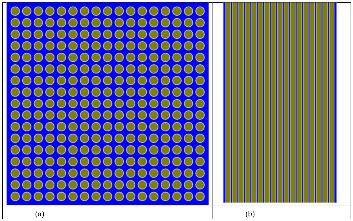
Figure 2.
Calculated neutron-energy spectrum for the modeled thorium-based PWR fuel assembly. The SHEM-361 energy-group structure was used for comparison of the energy-dependent neutron distribution.
Figure 2.
Calculated neutron-energy spectrum for the modeled thorium-based PWR fuel assembly. The SHEM-361 energy-group structure was used for comparison of the energy-dependent neutron distribution.
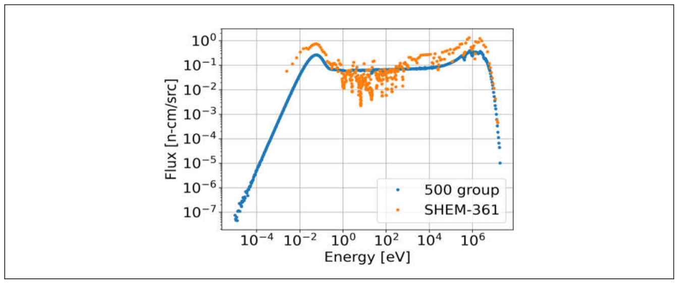
Figure 3.
Power-normalized neutron-flux and heat-generation distributions in a transverse cross-section at the mid-height of the modeled PWR fuel assembly.
Figure 3.
Power-normalized neutron-flux and heat-generation distributions in a transverse cross-section at the mid-height of the modeled PWR fuel assembly.
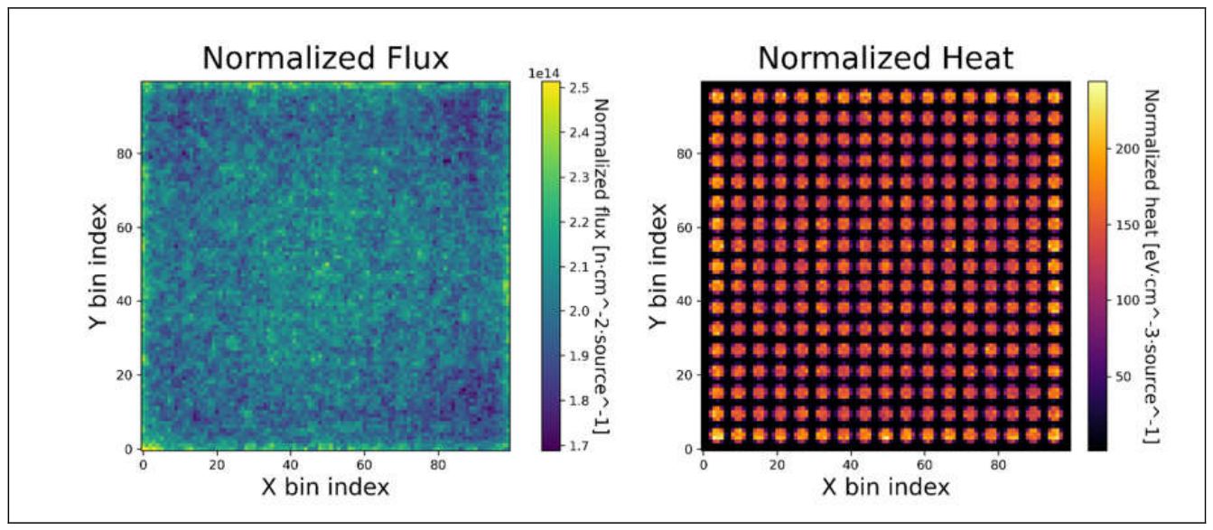
Figure 4.
Temperature distribution along radial distance at 1s, 5s and 10s of heating at three different heat sources: (a) 268 MW/m3, (b) 402 MW/m3 and (c) 536 MW/m3. (d) Temperature profile after 10s of heating at 536 MW/m3 heat source.
Figure 4.
Temperature distribution along radial distance at 1s, 5s and 10s of heating at three different heat sources: (a) 268 MW/m3, (b) 402 MW/m3 and (c) 536 MW/m3. (d) Temperature profile after 10s of heating at 536 MW/m3 heat source.
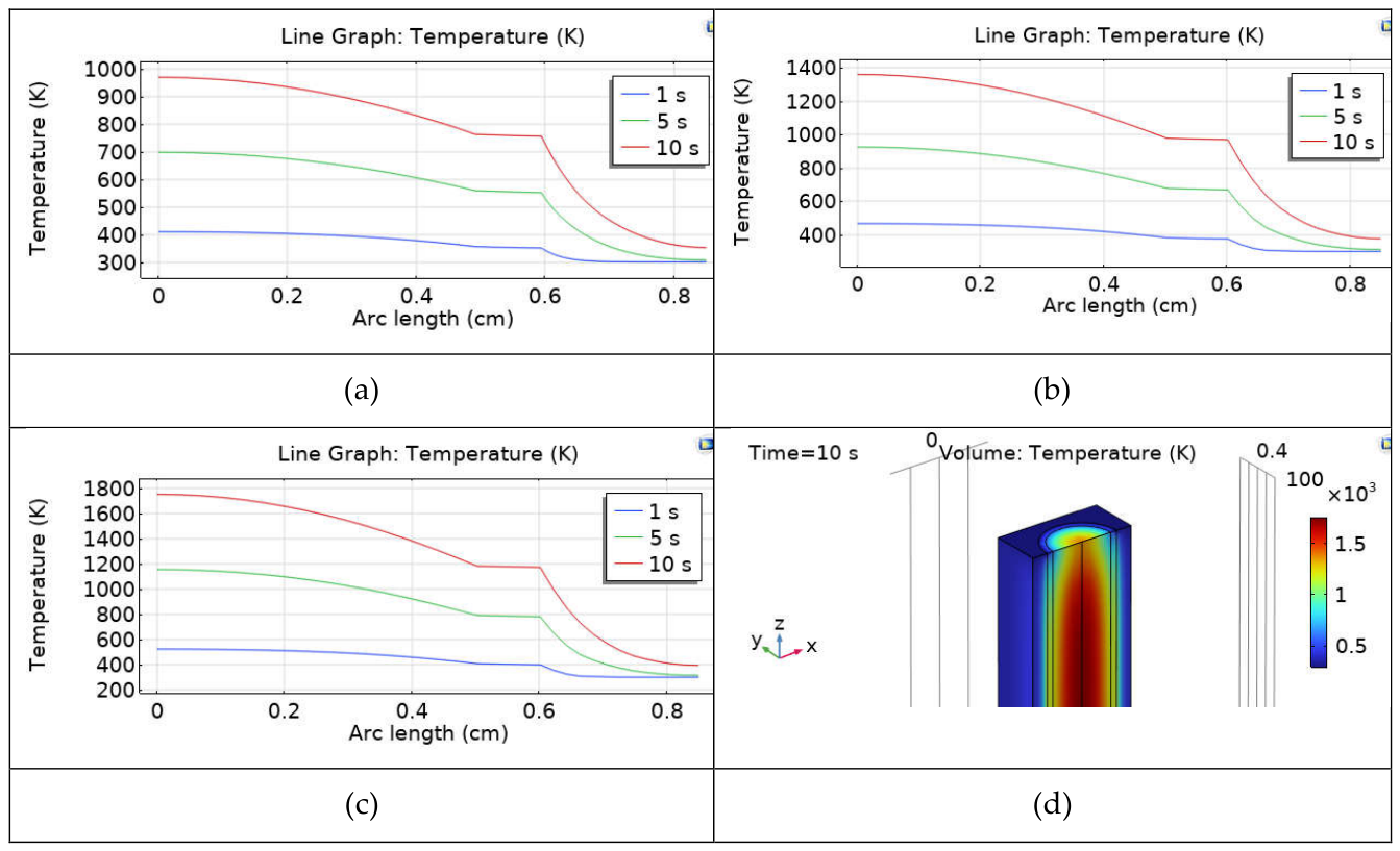
Figure 5.
(a) Coolant velocity magnitude along the height of reactor core at 0s, 1s, 5s and 10s time. (b) Coolant velocity profile after 10s of heating at 536 MW/m3 heat source.
Figure 5.
(a) Coolant velocity magnitude along the height of reactor core at 0s, 1s, 5s and 10s time. (b) Coolant velocity profile after 10s of heating at 536 MW/m3 heat source.
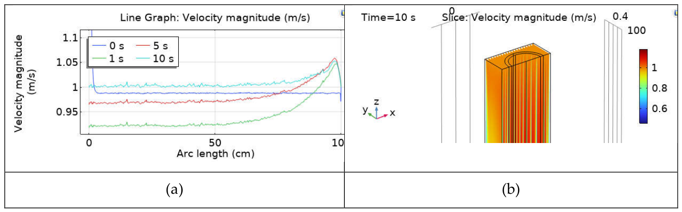
Figure 6.
Volumetric strain along the height of clad material at 0s, 1s, 5s and 10s of heating time at three different heat sources: (a) 268 MW/m3, (b) 402 MW/m3 and (c) 536 MW/m3.
Figure 6.
Volumetric strain along the height of clad material at 0s, 1s, 5s and 10s of heating time at three different heat sources: (a) 268 MW/m3, (b) 402 MW/m3 and (c) 536 MW/m3.
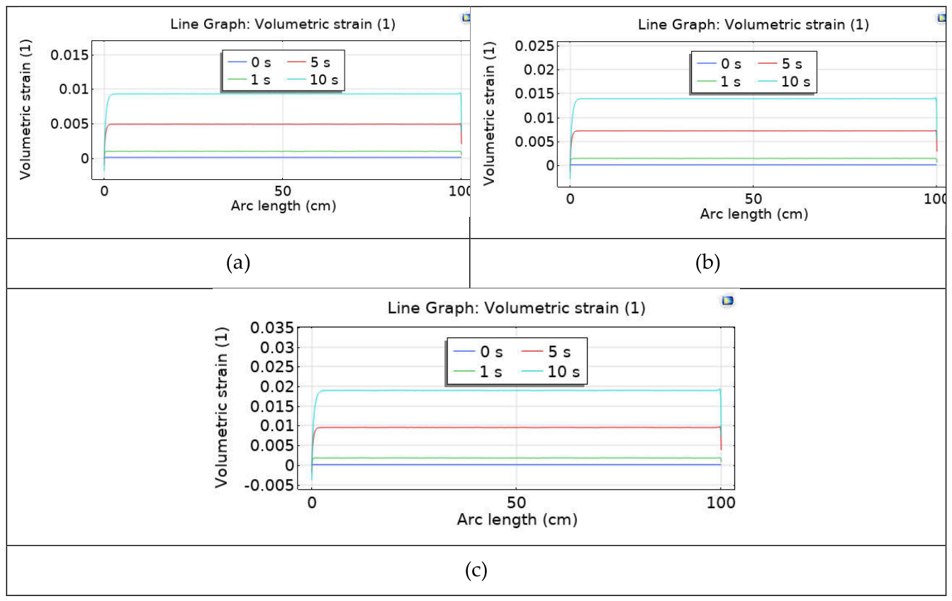
Figure 7.
Displacement magnitude along the height of clad material at 0s, 1s, 5s and 10s of heating time at three different heat sources: (a) 268 MW/m3, (b) 402 MW/m3 and (c) 536 MW/m3.
Figure 7.
Displacement magnitude along the height of clad material at 0s, 1s, 5s and 10s of heating time at three different heat sources: (a) 268 MW/m3, (b) 402 MW/m3 and (c) 536 MW/m3.
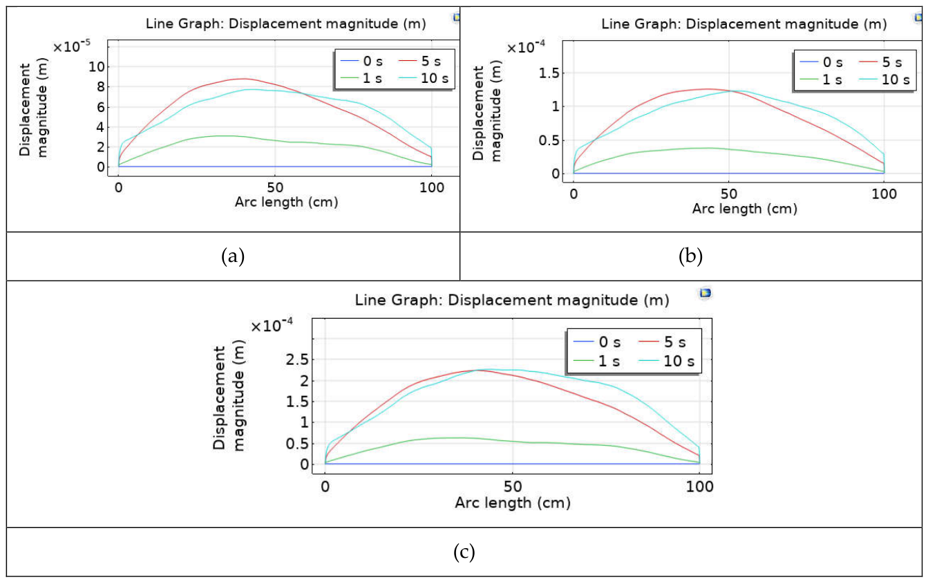
Figure 8.
von Mises stress along the height of clad material at 0s, 1s, 5s and 10s of heating time at three different heat sources: (a) 268 MW/m3, (b) 402 MW/m3 and (c) 536 MW/m3.
Figure 8.
von Mises stress along the height of clad material at 0s, 1s, 5s and 10s of heating time at three different heat sources: (a) 268 MW/m3, (b) 402 MW/m3 and (c) 536 MW/m3.
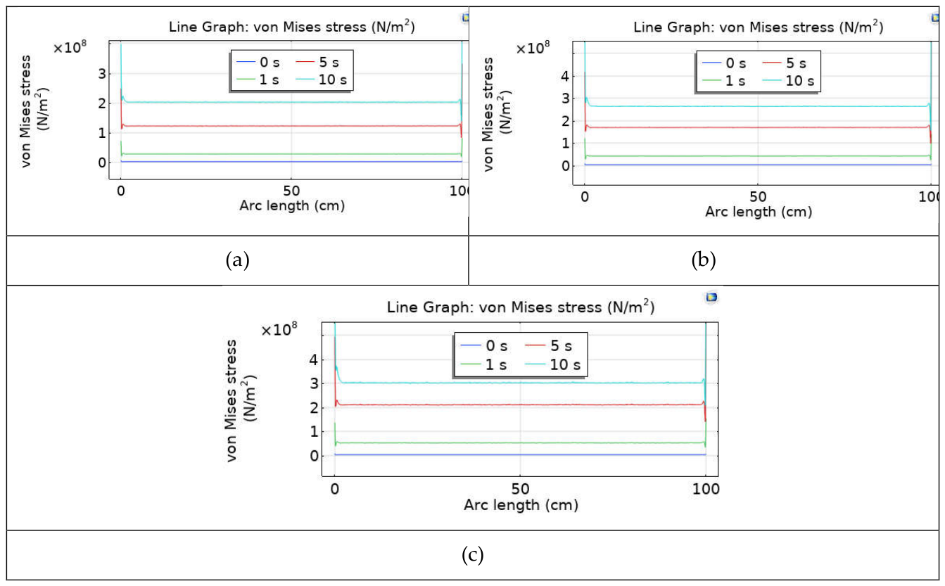

Table 1.
Geometrical and material parameters of the modeled PWR fuel assembly.
| Parameter | Value |
|---|---|
| Assembly geometry | Square |
| Fuel-pellet diameter | 1 cm |
| Fuel material | (Th,^233U)O₂ |
| Cladding material | Zircaloy-4 |
| Cladding thickness | 0.2 cm |
| Fuel-assembly configuration | 17 × 17 |
| Fuel-rod geometry | Cylindrical |
| Fuel-element height | 100 cm |
| Moderator | H₂O |
| Coolant | H₂O |
| Cladding rod radius | 1.2 cm |
| Cladding thickness | 0.2cm |
| Half-height and full height | 50 – 100 cm |
| Pitch length between the rods | 3 cm |
The exact composition of the (Th, 233U)O₂ fuel used in the OpenMC model: Th232/U233 = 0.985/0.015 at%; O16 = 2.0 at%, density = 10.0 g/cm3 (Fuel), Zr = 1.0 at%; Sn = 0.0145 at%; Fe = 0.0021 at%; Cr = 0.0009 at%; density = 6.0 g/ cm3 (cladding), H1 = 2.0 at%; O16 = 1.0 at%; density = 1.0 g/ cm3 (coolant).
Table 2.
Reactor thermal-power conditions and corresponding local volumetric heat-generation rates used in the transient fuel-rod analysis.
Table 2.
Reactor thermal-power conditions and corresponding local volumetric heat-generation rates used in the transient fuel-rod analysis.
| Reactor thermal power (MWth) | Volumetric heat-generation rate (MW m⁻³) |
|---|---|
| 60 | 268 |
| 90 | 402 |
| 120 | 536 |
Disclaimer/Publisher’s Note: The statements, opinions and data contained in all publications are solely those of the individual author(s) and contributor(s) and not of MDPI and/or the editor(s). MDPI and/or the editor(s) disclaim responsibility for any injury to people or property resulting from any ideas, methods, instructions or products referred to in the content. |
© 2026 by the authors. Licensee MDPI, Basel, Switzerland. This article is an open access article distributed under the terms and conditions of the Creative Commons Attribution (CC BY) license (http://creativecommons.org/licenses/by/4.0/).
Copyright: This open access article is published under a Creative Commons CC BY 4.0 license, which permit the free download, distribution, and reuse, provided that the author and preprint are cited in any reuse.