
Submitted:
13 November 2026
Posted:
16 November 2026
You are already at the latest version
Abstract
Collaborative robots are increasingly deployed in manufacturing, yet integrating third-party perception hardware into a unified, autonomous control stack remains difficult because industrial smart cameras typically offer only proprietary interfaces and no ready-made Robot Operating System (ROS) drivers. This paper presents a modular ROS-based control framework that turns a Universal Robots UR10 manipulator and a Robotiq 2F-85 adaptive gripper into a fully autonomous, vision-guided pick-and-place workstation. The framework was developed in two stages: a stable hardware-control layer for the arm and gripper, followed by the integration of a SensoPart VISOR V20 smart camera that supplies object position and orientation. The principal contribution is a generic, vendor-agnostic method for bridging a socket-server smart camera into ROS through a lightweight socket client and a custom ROS message, removing the dependence on manufacturer-specific URCaps. Gripper feedback was implemented through the ROS action protocol to confirm grasp completion, and perception, motion planning, and grasping were combined into an autonomous pipeline that eliminates manual entry of object coordinates. The workstation was validated in a real-world case study. Vision calibration yielded mean and maximum fiducial deviations of 0.597 mm and 1.121 mm, which bound the achievable positioning accuracy. The frame-work offers a replicable blueprint for vision-guided collaborative manipulation in ROS.
Keywords:
collaborative robot
; Universal Robots UR10
; Robot Operating System (ROS)
; machine vision
; perception pipeline
; autonomous pick-and-place
; smart camera integration
; vision-guided manipulation
1. Introduction
The automation of manufacturing operations has become a strategic priority for industry, offering substantial gains in productivity while relieving human workers of repetitive and physically demanding tasks [1,2,3,4]. Within this transformation, collaborative robots, or cobots, occupy a central role. Unlike conventional industrial robots that operate in isolation behind safety barriers, cobots are designed to share a workspace with human operators and to act as supportive hands rather than caged machinery [5,6]. The introduction of accessible, easily programmed collaborative arms has made such robots widely available, and models such as the Universal Robots UR10 are now routinely used for assembly, packaging, and pick-and-place operations on account of their flexible deployment and integrated safety functions [7,8]. Exploiting the full capability of these systems, however, depends on more than joint-level motion control; it requires accurate object localisation, robust path planning, and reliable gripper actuation operating in concert [9].
Perception is the capability that elevates a cobot from a pre-programmed actuator into an adaptive collaborator. Smart cameras and sensors supply real-time information about the workspace, enabling the robot to react to changing conditions and to operate without prior knowledge of where each object lies [10,11,12]. Vision-guided manipulation has consequently become a key enabler of flexible pick-and-place, in which the robot must detect, localise, and grasp parts whose positions are not fixed in advance [13,14,15,16]. Embedding a perception pipeline within the control stack therefore improves both the autonomy of the system and the fluency of the collaboration between human and machine.
The Robot Operating System (ROS) has become the de facto framework for building such systems, providing a modular publish-and-subscribe architecture that unifies robots, sensors, and actuators through reusable software packages [17,18,19,20]. A persistent obstacle, however, is the integration of third-party hardware. Manufacturers frequently expose their devices only through proprietary software or vendor-specific plug-ins, which limits interoperability and complicates the construction of a single, coherent control framework. Industrial smart cameras are a representative case: the SensoPart VISOR V20 employed in this work, like many comparable sensors, communicates through a proprietary socket interface and is supplied with a URCap for direct use from the teach pendant of the robot, yet it has no publicly available ROS driver or interface [21]. Its detection output therefore cannot be consumed natively within a ROS-based pipeline without a bespoke solution, and the available vendor path ties the application to a single robot programming environment.
This paper addresses that gap. It presents the design, development, and integration of a modular ROS-based control framework that transforms a UR10 manipulator and a Robotiq 2F-85 adaptive gripper into a fully autonomous, vision-guided manufacturing workstation (Figure 1). The framework was developed in two stages at the Laboratory of Intelligent Machines of LUT University. The first stage established a stable hardware-control layer for the arm and the gripper, together with an extensible network deliberately structured so that additional sensors could be added without altering the existing topology. The second stage built upon this foundation by integrating the VISOR V20 through a generic socket interface, by adding bidirectional gripper feedback, and by combining perception, motion planning, and grasping into a single autonomous pick-and-place application, which was then validated in a real-world case study. This article consolidates and extends the results of two theses completed within this project: a bachelor’s thesis on the control framework [22] and a master’s thesis on the perception-based workstation [23].
Integrating perception into a robotic control stack is not in itself new, and several established frameworks address parts of the problem. The Robot Operating System provides the message-passing substrate and a large ecosystem of drivers and tools [24], while the MoveIt framework adds motion planning together with a perception pipeline that fuses depth sensors into a planning scene [25,26]. ROS-Industrial extends this ecosystem to manufacturing hardware and standardises drivers for common industrial manipulators [27]. For camera integration specifically, the conventional routes are an open-source ROS driver that exposes a sensor as standard image or point-cloud topics, or a computer-vision pipeline built on a library such as OpenCV that processes a raw camera stream inside ROS, as in recent Universal Robots cells that combine industrial, depth, or wrist cameras with classical or deep-learning detection [28,29]. Both work well for sensors that expose either a documented ROS driver or a raw image interface.
Industrial smart cameras, however, fall outside both routes. Sensors such as the VISOR perform detection on-board and expose only a proprietary result interface, typically a configurable TCP/IP telegram together with a vendor plug-in (a URCap) for direct use from a specific robot’s teach pendant, rather than a raw image stream or a public ROS driver. Consequently they cannot be consumed natively by a ROS perception pipeline, and the vendor plug-in ties the application to a single robot programming environment, undermining the interoperability a ROS-based cell is meant to provide; the common fallback of entering object coordinates manually removes autonomy altogether. The contribution of this work is to close this gap with a deliberately generic abstraction: treating the smart camera as a socket server and bridging it into ROS through a lightweight socket client and a custom message. Because the bridge depends only on a generic TCP/IP telegram rather than any vendor SDK, the same architecture and message interface transfer to any smart camera able to transmit detection results over a socket, making the integration a reusable, vendor-independent component rather than a one-off driver. It thus sits between the device-specific drivers of ROS-Industrial [27] and the raw-stream pipelines of MoveIt [25], addressing the class of closed, result-only industrial sensors that neither covers.
Mapping the sensor’s detections into the robot frame is a hand-eye calibration problem; here the camera is fixed above the workspace looking down, an eye-to-hand configuration. The accuracy attainable from such calibration, and its dependence on the calibration target and method, are well documented [30,31,32,33], and sub-millimetre perceptual accuracy is known to be difficult to guarantee, a consideration that directly bounds the precision of the vision-guided placement reported here and is examined quantitatively in Section 5. Vision-guided pick-and-place and bin-picking systems built on such calibration are widespread in industry [34]; the present work contributes not a new detection or grasping algorithm but an open, reusable means of bringing a closed industrial sensor into a ROS-based collaborative cell.
The main contributions of this work are as follows:
- A modular and extensible ROS-based control framework that unifies the Universal Robots UR10 manipulator and the Robotiq 2F-85 gripper and is structured so that additional sensors can be incorporated without reconfiguring the existing network.
- A generic, vendor-agnostic method for integrating a socket-server smart camera (in this work, the SensoPart VISOR V20) into ROS by means of a lightweight socket client and a custom ROS message, providing a reusable alternative to proprietary, manufacturer-specific interfaces.
- An implementation of bidirectional gripper communication through the ROS action protocol, supplying feedback on the completion of every gripper command so that the application never proceeds blindly.
- The integration of perception, motion planning, and grasping into a fully autonomous pick-and-place pipeline that removes the need to enter object positions and orientations manually, validated in a real-world case study and offered as a replicable blueprint for vision-guided collaborative cells.
The remainder of this paper is organised as follows. Section 2 describes the hardware components and the communication methodology, including the vision sensor and its calibration. Section 3 details the control of the UR10 arm and the gripper within ROS. Section 4 presents the perception-based pick-and-place case study. Section 5 reports the experimental results, Section 6 discusses their implications and limitations, and Section 7 concludes the paper and outlines directions for future work.
2. Hardware Setup and Communication Methodology
This section describes the physical components of the collaborative workstation and the communication architecture that integrates them within ROS. The workstation comprises a Universal Robots UR10 manipulator, a Robotiq 2F-85 two-finger adaptive gripper, and a SensoPart VISOR V20 smart camera, coordinated by a host computer running ROS. A central design requirement was modularity: the network was structured so that additional sensors could be introduced without altering the existing topology, allowing the perception layer of Section 4 to be added on top of a stable hardware-control foundation.
2.1. UR10 Collaborative Robot
The UR10, shown in Figure 2, is a six-axis collaborative robot of the Universal Robots CB3 series [35]. It combines a reach of 1300 mm with a rated payload of 10 kg and a pose repeatability of ±0.1 mm, while its lightweight construction and rounded, padded contours allow it to share a workspace with human operators. The arm consists of six revolute joints, the base, shoulder, and elbow, and wrists 1 to 3, with the tool flange located at the third wrist. Each joint may be commanded individually, or the controller’s inverse kinematics may be used to drive the tool relative to a chosen coordinate frame. By default the robot is programmed through the attached teach pendant using the manufacturer’s PolyScope graphical interface. The principal specifications are summarised in Table 1.
Beyond pendant-based programming, the CB3 controller exposes a remote-control interface over a TCP/IP socket known as the dashboard server [36]. A client can transmit simple ASCII commands, each terminated by a newline character, to the server on port 29999 to query the robot state or to load, start, and stop programs. A representative subset of these commands is listed in Table 2; this interface is later used to place the robot under external control from ROS.
2.2. Robotiq 2F-85 Adaptive Gripper
End-effector actuation is provided by a Robotiq 2F-85 two-finger adaptive gripper, shown in Figure 3. A two-finger design was selected because it grips geometrically complex objects more evenly than a three-finger equivalent, which can impart unwanted rotation or fail to close on irregular parts. The gripper offers an 85 mm stroke, a programmable grip force of 20–235 N, and a closing speed of 20–150 mm/s, with a position resolution of 0.4 mm (at the fingertips) and a rated payload of 5 kg. Its underactuated fingers can hold a part either in a parallel grip between the fingertips or in an encompassing grip, in which the phalanges wrap around the object and press it against the palm (Figure 3c,d). It communicates over Modbus RTU on an RS-485 link. Its full specifications are listed in Table 3 [37].
2.3. SensoPart VISOR V20 Smart Camera
Autonomous operation requires the workstation to locate workpieces without pre-programmed coordinates. This capability is supplied by a SensoPart VISOR V20 robotic vision sensor, shown in Figure 4, which integrates image acquisition and on-board processing for object detection, measurement, identification, and position tracking [21]. Its specifications are given in Table 4.
The sensor used here, a VISOR V20 Robotic Advanced with C-mount (V20C-RO-A3-C-2), has a 1/2.9″ colour CMOS image sensor with a resolution of 1440 × 1080 pixels and a pixel pitch of 3.45 µm, a C-mount lens interface, and can store up to 255 jobs, each containing up to 255 detectors [38]. With the 8 mm lens used in this work, the field of view grows linearly with the working distance d, to approximately 0.62d × 0.47d (Figure 4c); at d = 600 mm, for example, it covers about 373 × 279 mm. At the mounting height used in this work, about 1.35 m above the working plane (Section 2.3.1), the field of view is about 840 × 630 mm, which encloses the 500 × 379.2 mm calibration plate with margin and corresponds to an image scale of about 0.58 mm per pixel.
The sensor is configured through a suite of three software modules, SensoFind, SensoConfig, and SensoView, whose roles are illustrated in Figure 5. SensoFind is the master module, used to discover sensors on the network, manage connection parameters, and update firmware. SensoConfig, launched from SensoFind once a sensor is selected, defines jobs and detectors and sets image-acquisition parameters such as shutter speed and gain. SensoView, likewise started from SensoFind, is used to monitor a running sensor and to inspect detection results. Of the available detector types, the pattern-matching and contour detectors are the two capable of locating arbitrary objects within the field of view, and both were employed in this work.
2.3.1. Calibration of the Vision Sensor
Because detection results are reported in the sensor’s image space, the VISOR must be calibrated so that pixel coordinates can be mapped into the robot’s Cartesian frame. Robot positions on the UR10 are expressed in right-handed coordinate systems known as features: the base coordinate system, whose z-axis points upwards through the centre of the base joint and whose y-axis points towards the robot cable (Figure 6a), and the tool coordinate system attached to the tool flange, whose z-axis is normal to the flange (Figure 6b) [40]. Motion commands, and therefore the calibrated object positions, refer to the base coordinate system [40]. In its robotics-calibration mode, the VISOR projects its camera coordinate system onto this robot coordinate system (Figure 6c) [21]. Calibration uses a 500 × 379.2 mm calibration plate (Figure 6f) that carries a regular grid of dots, from which the sensor determines the mapping between pixels and millimetres, and four ring-shaped fiducials at its corners [21,38]. The robot-frame coordinates of the four fiducials are taught by positioning the robot’s tool centre point on each of them, so that every fiducial is known in both image and robot coordinates [21]; the successful detection of the plate in the VISOR software during the calibration of this workstation is shown in Figure 6e. Because the calibration is valid for the plane of the plate, objects whose upper surface lies above or below that plane require a corresponding z-shift ΔZ of the measurement plane (Figure 6d) [21]; a z-shift of −15 mm was used in this work.
The procedure establishes the planar transformation between the image plane and the working surface, a planar special case of the eye-to-hand calibration problem [30,31], after which detected object positions can be expressed directly as robot coordinates. The calibration placed the camera about 1338 mm above the robot base, looking down on the table at a tilt of about 9° from the vertical (Section 5.2). The resulting coordinates refer to the robot base frame and to the tool centre point as configured on the teach pendant, from which the fiducial coordinates were read; they therefore do not include the geometry of the gripper for which MoveIt plans, and the corresponding offset is applied afterwards in the vision node (Section 4.2). The accuracy of this mapping bounds the positioning accuracy achievable by the complete pipeline; the quantitative calibration results and their implications for high-precision tasks are reported in Section 5.2.
2.4. Communication Methodology
The control software runs on a host computer, a Dell OptiPlex 7050 running Windows 10, that hosts an Ubuntu 18.04 LTS virtual machine under Oracle VirtualBox; the ROS Melodic Morenia distribution executes inside this virtual machine [18]. The host specifications are listed in Table 5, and the physical interconnection of the workstation is shown in Figure 7. To keep the system extensible, all networked devices are joined through a single HP ProCurve 408 Ethernet switch acting as a hub: the host, the UR10 controller (at IP address 192.168.100.103), and the VISOR camera each connect to the switch, so that further Ethernet devices can be attached without reconfiguring the existing links. The gripper, which uses a serial protocol, is connected to the host through a USB-to-RS-485 adapter.
Within ROS, computation is organised as a graph of independent processes, called nodes, each responsible for a single device or task, that communicate by passing messages [24]. A node publishes messages to a named topic, and any node subscribed to that topic receives them; the underlying TCPROS transport routes these messages over standard TCP/IP sockets, while a central ROS master coordinates the registration and discovery of nodes and topics. The resulting computation graph for the complete workstation is shown in Figure 8. The camera streams detection results over a TCP/IP socket to a vision node, which parses them and publishes the object pose as a custom ROS message; a pick-and-place node consumes this pose, issues motion goals to the MoveIt planning node, and commands the gripper, while the corresponding hardware drivers translate these high-level messages into the UR robot driver’s control stream and the gripper’s Modbus traffic. The design and operation of these nodes are detailed in Section 3 and Section 4.
3. Control of the UR10 Robotic Arm and Gripper
This section establishes the hardware-control layer of the framework: the representation of orientation used to command the manipulator, the integration of the UR10 and the gripper within ROS, and the motion-planning configuration through which collision-free trajectories are generated and executed. Together these elements form the stable foundation on which the perception-based application of Section 4 is built.
3.1. Representation of Orientation in Three-Dimensional Space
Precise control of end-effector orientation is fundamental to manipulation. A common way to describe orientation is through Euler angles, which, by Euler’s rotation theorem, express an arbitrary rotation using only three parameters. Adopting the x-convention (a z–x′–z″ rotation sequence) [41] illustrated in Figure 9, the orientation of a rotated coordinate system (x′, y′, z′) relative to a fixed coordinate system (x, y, z) is obtained through three successive elementary rotations, so that the overall rotation is written as the product of three rotation matrices, as in Equation (1).
For the x-convention the rotations are applied in a fixed order: a rotation by an angle φ about the z-axis (matrix D), followed by a rotation by θ about the resulting x′-axis, known as the line of nodes (matrix C), and finally a rotation by ψ about the resulting z″-axis (labelled z′ in Figure 9; matrix B). The three panels of Figure 9 show these rotations in turn. These elementary rotation matrices are given in Equations (2)–(4).
Carrying out the matrix multiplication in Equation (1) yields the complete Euler rotation matrix of Equation (5).
Euler-angle representations suffer from a singularity known as gimbal lock, in which a 90° rotation about one axis causes two of the remaining axes to align and a degree of freedom is momentarily lost. To avoid this, the MoveIt motion-planning framework represents orientation with quaternions, which describe a rigid-body rotation as a four-dimensional vector [43]. A quaternion is written as in Equation (6), where q0 is a real scalar and the remaining components form a vector in imaginary space.
The imaginary units obey Hamilton’s multiplication identities, given in Equation (7).
An ordinary three-dimensional vector (x, y, z) is embedded in quaternion form as a pure quaternion v with a zero scalar part, as in Equation (8), whereas an orientation is represented specifically by a unit quaternion, whose norm is unity as defined in Equation (9).
A rotation by an angle θ about a unit axis a = (ax, ay, az) is then expressed by the unit quaternion of Equation (10), written here and throughout the paper in scalar-first order (qw, qx, qy, qz); this is the form used to command end-effector orientation in this work.
3.2. Integration and Control of the UR10 in ROS
Placing the UR10 under ROS control begins by installing the external-control URCap on the robot, which runs as a consent program within PolyScope and grants an external ROS driver authority over the arm [44]. To preserve end-effector accuracy, the joint-level kinematic calibration stored in the controller is first extracted to a configuration file, as shown below.

The driver is then launched with this calibration passed as an argument, after which the arm is exposed to ROS as a controllable device through the ros_control framework [45].

Motion planning requires a kinematic and geometric model of the manipulator. This is provided by a Unified Robot Description Format (URDF) model [46], authored as a set of Xacro macros, that represents the robot as a tree of rigid links connected by joints, each link carrying inertial, visual, and collision geometry. The link-and-joint tree for the UR10 with the gripper attached is shown in Figure 10. From this description a MoveIt configuration package is generated with the setup assistant [25,26], which computes the self-collision matrix, defines a virtual base joint, and assigns a planning group spanning the kinematic chain. Because the gripper is added to the chain, a dedicated tool-centre-point link (arm_tcp_link) is defined 171 mm along the tool axis from the robot flange, and the planning group is defined from the base link to this new tool centre point; the gripper joints themselves are declared passive and are actuated separately rather than through MoveIt.
Each joint of the model defines a rigid-body transformation between successive link frames. Such a transformation is expressed compactly as a 4 × 4 homogeneous matrix combining a rotation and a translation, as in Equation (11).
The pose of the tool frame relative to the base is then obtained by composing the individual joint transformations along the chain, giving the forward-kinematics product of Equation (12).
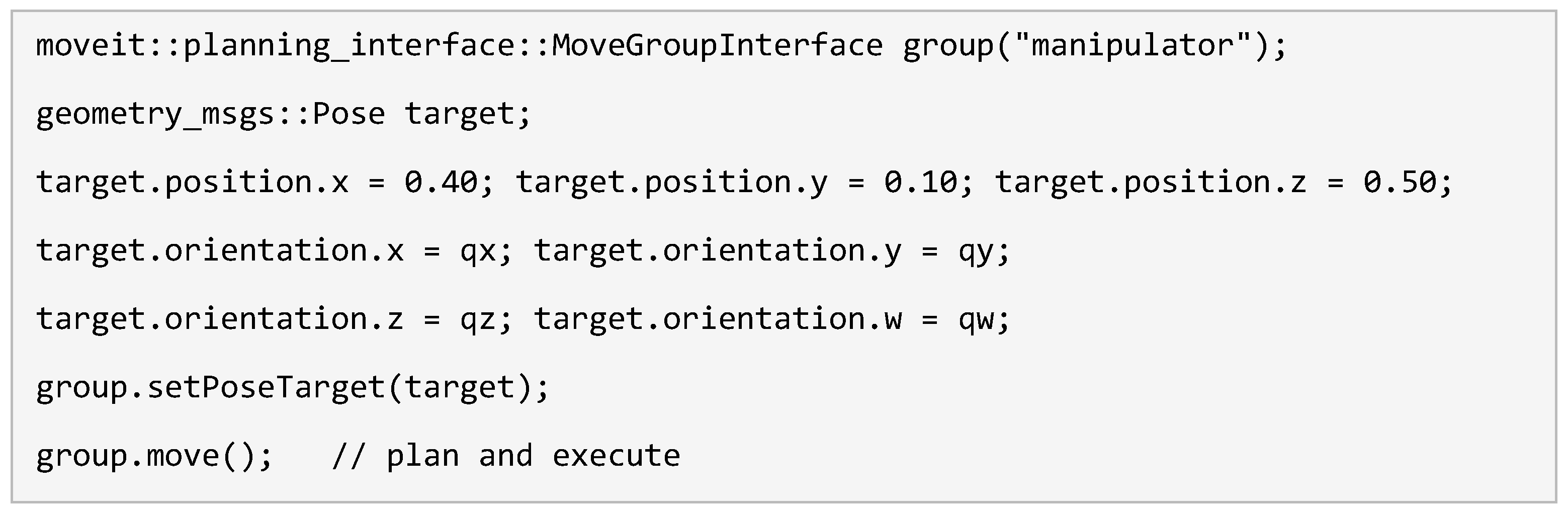
With the model and driver in place, the arm is commanded through the MoveIt C++ MoveGroup interface by specifying a target pose for the planning group. A pose goal combines a Cartesian position p with a unit-quaternion orientation q, as defined in Equation (13) (the ROS geometry_msgs/Pose message stores the same quaternion in the component order x, y, z, w); MoveIt solves the inverse kinematics and plans a collision-free trajectory to reach it. The robot and its planning scene, in which the worktable is modelled as a collision object, are visualised in RViz, as shown in Figure 11a; the corresponding physical workstation is shown in Figure 11b.
3.3. Integration and Control of the Gripper
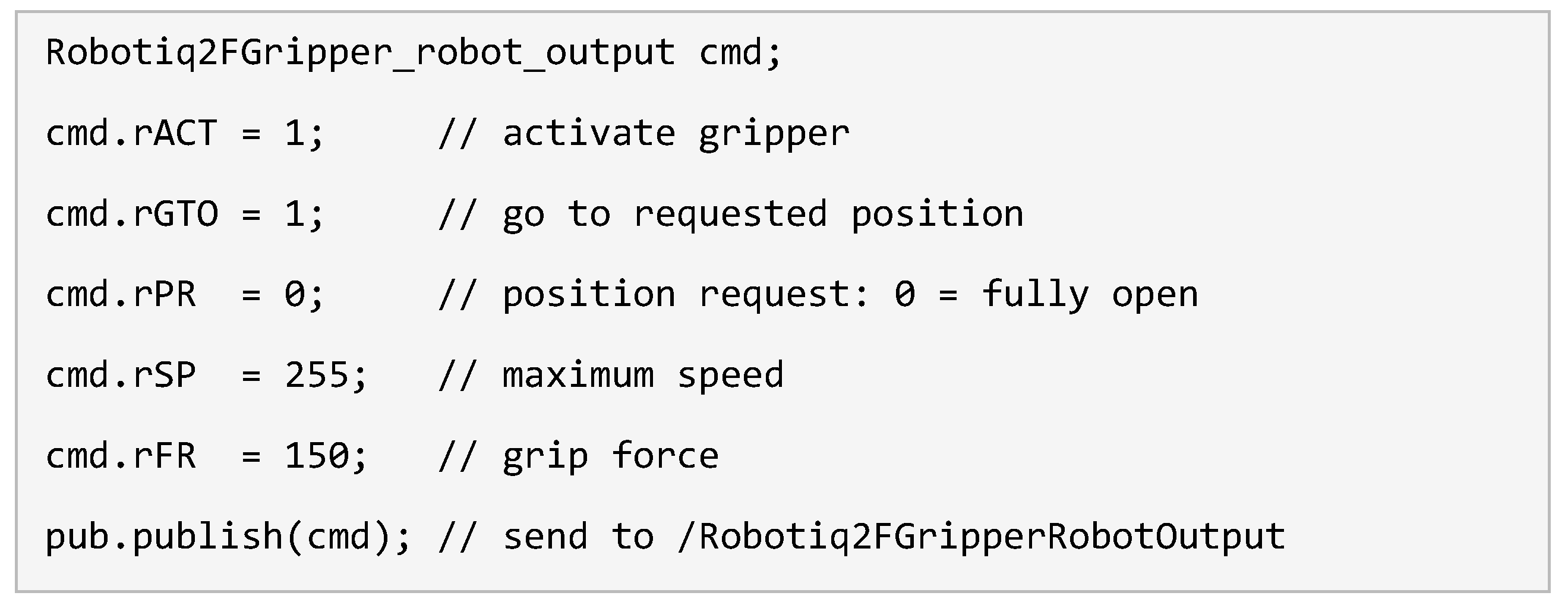
In the first-stage framework [22], the gripper is driven through the Robotiq ROS package [47]. The control node publishes control messages to the gripper’s output topic, /Robotiq2FGripperRobotOutput, to which the Robotiq driver node subscribes; the driver then relays the corresponding low-level commands to the gripper over Modbus RTU. Each control message carries six unsigned 8-bit fields that set the activation, motion, and force parameters of the gripper; their meanings are summarised in Table 6.
A gripper action is issued by populating these fields in a message of type Robotiq2FGripper_robot_output and publishing it to the topic. For example, the gripper is activated and driven to the fully open position with the assignment below.
3.4. Motion Planning and Collision Environment
Trajectories are generated through the MoveIt motion-planning pipeline, illustrated in Figure 12, which exposes a plugin interface to several planning libraries [25]. The default Open Motion Planning Library (OMPL) [48] was used here. OMPL is a sampling-based library, it tests candidate configurations for collisions rather than constructing an explicit map of the free space, and provides a range of algorithms including the Probabilistic Roadmap Method [49], Rapidly-exploring Random Trees (RRT) and their bidirectional RRT-Connect variant [50], and Kinodynamic Motion Planning by Interior–Exterior Cell Exploration (KPIECE) [51]; a recent comparative review of these planner families is given in [52]. Three planners were evaluated in this work: RRT-Connect, KPIECE, and the Lazy Bidirectional KPIECE variant (LBKPIECE1). Within the move_group node, a planning request is first pre-processed by planning request adapters that correct the start state and enforce the workspace bounds; the selected OMPL planner then searches for a collision-free path against the current planning scene, and the path is shortened and smoothed by OMPL’s path simplifier. A post-processing adapter finally adds time parameterisation, assigning velocities and accelerations within the joint limits, and the trajectory is executed through the FollowJointTrajectory action served by ur_robot_driver [44].
To plan safely, the manipulator’s surroundings are represented in the MoveIt planning scene as collision objects. Each object is added through the planning-scene interface as a primitive box with a defined pose and size. Four boxes were defined: the 0.6 × 0.9 × 0.07 m worktable, the left and right walls that bound the workspace, and a floor plane below the table, so that the planner avoids all fixed obstacles. The robot together with its collision environment is visualised in RViz, as shown in Figure 13.
3.5. Motion-Planning Functionality Experiment
The configured control and planning layer was verified [22] with a simple repeatable task in which the manipulator was driven from an initial start pose to a wait pose and back, emulating the motion pattern of a pick-and-place cycle. The two poses are shown in Figure 14. Both were specified as pose goals in the planning frame: the start pose at (x, y, z) = (−0.20, 0.98, 0.03) m, with the gripper just above the table surface, and the wait pose at (0.40, 0.50, 0.40) m, with the gripper raised clear of the workspace. In both cases the orientation quaternion was (qw, qx, qy, qz) = (0, 1, 0, 0), entered as orientation.x = 1 in the ROS Pose message, a 180° rotation about the x-axis that points the gripper vertically downwards. The task was executed in turn with each of the three planners, RRT-Connect, KPIECE, and LBKPIECE1, and the planning time required to generate the trajectory was recorded for each. This experiment isolates the effect of the planning algorithm on the latency of the manipulation cycle; the measured results and their interpretation are reported in Section 5.1.
4. Case Study: Perception-Based Pick-and-Place
The hardware-control layer of Section 3 provides reliable manipulation from explicit pose goals, but it still requires object locations to be specified in advance. This section presents the perception layer that closes this gap and a real-world pick-and-place case study built upon it. The application realises a scenario in which a human operator collaborates with the robot: the camera locates a workpiece on the workstation, the system computes a grasp pose, and the robot autonomously picks and relocates the part. The work also restructures the software architecture of the earlier framework [22], separating the single overloaded control node into dedicated vision and application nodes, and adding bidirectional gripper feedback, so that the pipeline is modular and fault-aware.
4.1. Application Architecture and Algorithm
Whereas the earlier framework concentrated all functionality in one node, the perception-based application distributes responsibility across cooperating nodes coordinated by a pick-and-place node that acts as the application master. At runtime this node obtains the object pose from the vision node, requests a collision-free trajectory from MoveIt to approach the object, actuates the gripper through its action server, and then transfers the object to a place location. The control logic of one complete cycle is shown in the flowchart of Figure 15, and the collaborative scenario it serves is illustrated in Figure 16.
4.2. Perception and Object Localisation
The vision node is the bridge between the camera and ROS. It opens a TCP/IP socket as a client to the VISOR, which acts as the socket server at IP address 192.168.100.4 on port 2005 [21], using the standard Berkeley socket interface, as shown below.

On each cycle the node reads the telegram transmitted by the sensor, which carries the detection state, the object’s x- and y-coordinates, and its angle, and parses the fields on a configured delimiter. Although the VISOR already reports calibrated robot coordinates (Section 2.3.1), two corrections are applied as the fields are read. First, the calibration was taught with the tool centre point configured on the teach pendant and therefore omits the gripper, whereas MoveIt plans for the gripper’s own tool centre point (arm_tcp_link, Section 3.2); the residual planar offset (x_cal, y_cal) between the two is added in the vision node. Second, the sensor’s x- and y-outputs are assigned to the robot’s y- and x-axes, respectively, to match the axis convention of the ROS planning frame. The resulting planar mapping is given in Equation (14), with (tx, ty) = (−x_cal, y_cal); positions are converted to metres and rounded to the nearest millimetre. Because the axis swap reverses the handedness of the in-plane coordinates, the reported angle α_c is rounded to whole degrees and negated, θ = −α_c, before use.
The converted pose is stored and, once per loop, published to the camera_output topic as a custom vision_output_msg containing four fields, defined as follows.
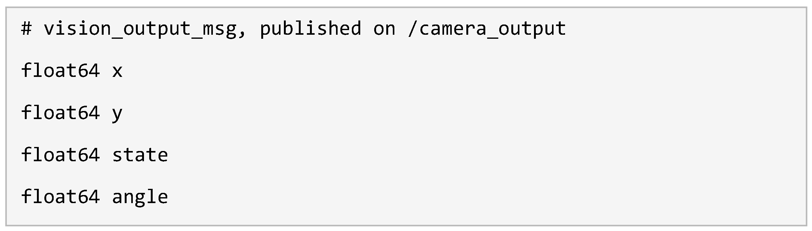
The pick-and-place node subscribes to this topic and refreshes its object pose through a callback invoked at the start of each loop, so that perception and manipulation execute as decoupled but communicating processes. A representative detection after configuration and calibration is shown in Figure 17: the sensor locates the object with a matching score of 99.1 and reports its position and orientation directly in millimetres and degrees in the calibrated table plane.
4.3. Grasp-Pose Generation
From the localised object the application constructs a grasp pose. The position is taken from the transformed coordinates (x_r, y_r). The arm first moves to an approach pose 0.15 m above the object and then descends, at 2% of its maximum velocity, to a fixed grasp height z_pick = 0.04 m in the planning frame, chosen for the test workpieces; the −15 mm z-shift of the measurement plane (Section 2.3.1, Figure 6d) ensures that the detected position refers to the upper surface of the workpiece rather than to the calibration plane. The orientation first turns the gripper’s approach axis to point vertically downwards, by a rotation of π about the robot’s x-axis, and then aligns the fingers with the object angle θ by a rotation about the vertical axis; composing the two rotations gives the unit quaternion of Equation (15), whose rotation matrix maps the tool z-axis onto (0, 0, −1) and the tool x-axis onto (cos θ, sin θ, 0). In the implementation the two rotations are built with the tf2 setRPY function using a roll of −π, which yields the negated quaternion and therefore the same rotation.
The position and orientation together define the pose goal dispatched to MoveIt, given in Equation (16); MoveIt then solves the inverse kinematics and plans a collision-free trajectory to the grasp, exactly as described in Section 3.2.
4.4. Bidirectional Gripper Control via the Action Protocol
In the earlier framework the gripper was driven open-loop by publishing to a topic, leaving the application unaware of whether a grasp had succeeded. Here the gripper is instead given its own node and controlled through the ROS action protocol [53], which augments the command stream with goal, result, and feedback channels. The application sends a gripper-command goal to the Robotiq action server specifying a target finger position and a maximum effort; the server forwards the command to the Robotiq driver node (Robotiq2FGripperRtuNode), which actuates the gripper over Modbus RTU, and reports progress and completion back to the application.
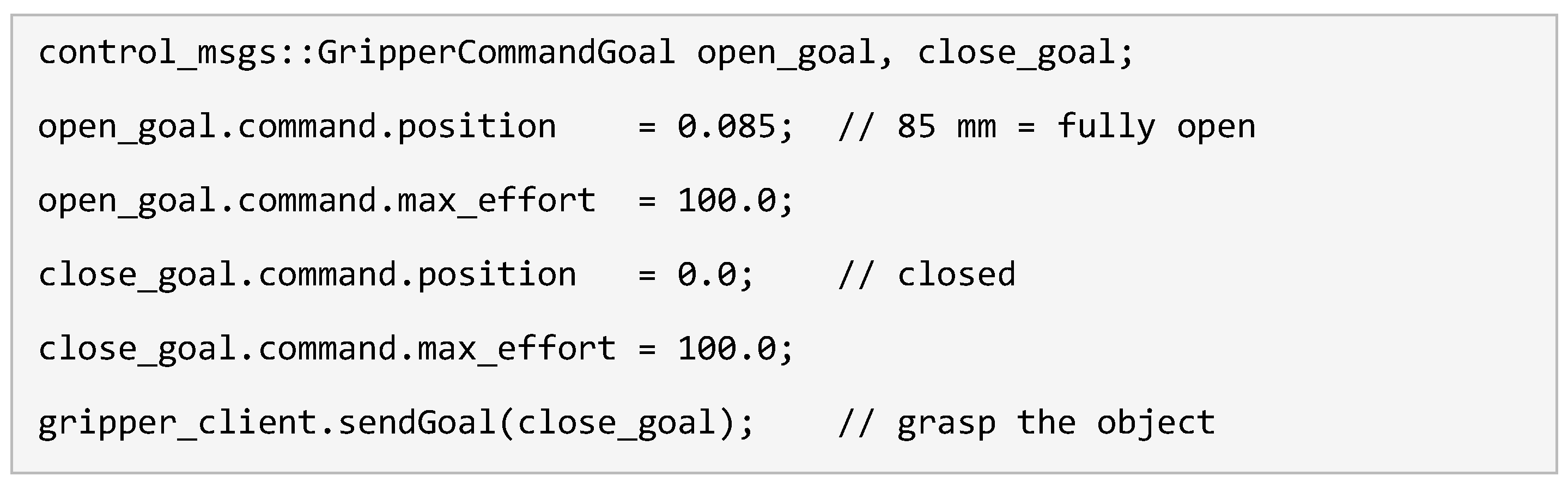
The application waits up to 30 s for each action result before moving on, so the arm does not lift until the gripper has finished closing, and the reported action state is logged in every cycle. A gripper that fails to respond within this timeout during the start-up check halts the application instead of letting it proceed blindly, as represented by the decision node in Figure 15, a capability absent from the earlier one-way design.
5. Experiments and Results
This section reports the experimental evaluation of the framework: the efficiency of the motion planners, the accuracy of the vision calibration, the validation of the perception pipeline, and the integrated pick-and-place demonstration.
5.1. Motion-Planner Efficiency
Using the start–wait–start task of Section 3.5, the planning time of the three OMPL planners was compared [22]. RRT-Connect produced trajectories with a negligible planning delay and was the best suited to this simple manipulation task; KPIECE was moderately slower; and LBKPIECE1 was substantially slower, requiring several seconds per query and proving unsuitable for the application. The trajectory-simplification time followed the same ordering. The measured planning times are shown in Figure 18.
5.2. Vision Calibration Accuracy
The robotic calibration of the VISOR using the calibration plate and four fiducial points was successful [23]; its parameters and results are summarised in Table 7. The sensor reports two different accuracy measures. The plate-grid residual describes how well the camera model fits the detected dot grid; it ranged from 0.004 px to 0.115 px, with a mean of 0.045 px. The fiducial deviation compares the robot coordinates entered for the four fiducials with those recovered by the calibration; it ranged from 0.069 mm to 1.121 mm, with a mean of 0.597 mm. With the camera about 1.35 m above the working plane, one pixel spans about 0.58 mm, so the maximum fiducial deviation corresponds to about 1.9 px, roughly 17 times the largest grid residual. The camera model therefore fits the image to well below one pixel, and the fiducial deviation is dominated by the manual teaching of the fiducials: the tool centre point was placed on each marking by eye, using the standard two-finger gripper rather than a dedicated calibration tool, and the plate was not fixed to the table [23]. Both measures are shown in Figure 19.
While these deviations confirm that the calibration is accurate enough for the demonstrated pick-and-place task, the maximum fiducial deviation of 1.121 mm shows that the calibration, performed by this manual four-point method, cannot be relied upon for high-precision tasks requiring sub-millimetre tolerances. The achievable positioning accuracy of the complete pipeline is therefore bounded by this calibration step rather than by the manipulator’s own ±0.1 mm repeatability.
5.3. Perception-Pipeline Validation
The perception pipeline was validated in stages. The VISOR was first confirmed to detect the taught object contour across the entire workstation surface, reporting the object’s position in millimetres as a result of the successful calibration. The socket client was then tested in isolation as a plain C++ program that connected to the sensor and printed the received telegram, before the same socket logic was integrated into the vision node. With the ROS master running, the vision node successfully established the socket connection, read the sensor data on each cycle, parsed the fields, and published them to the camera_output topic, confirmed by inspecting the live message stream with the rostopic echo command.
5.4. Integrated Pick-and-Place Demonstration
Finally, the complete framework was exercised in the pick-and-place case study [23], launching the vision node, the pick-and-place node, the gripper action server, and the MoveIt planning components together. The system performed the full cycle autonomously: the camera located the workpiece, the application computed and reached the grasp pose, the gripper closed under action control, and the object was transferred to its place location, with successful manipulation confirmed by the feedback reported by the UR driver. The application loop was configured to run four consecutive cycles, each ending with the arm back at its wait pose. Figure 11b shows the physical workstation during this autonomous operation, with the workpieces placed on the worktable.
The runtime computation graph in Figure 20 shows all components, the pick-and-place node, the vision node, the gripper action server, the UR hardware interface, and the MoveIt move_group, communicating as designed. The case study thus demonstrates an end-to-end, vision-guided pick-and-place cycle with no manually entered object coordinates. It constitutes a functional demonstration of the integrated system rather than a statistical performance benchmark; quantitative throughput and success-rate characterisation is identified as future work.
5.5. Proposed Evaluation Protocol
The case study of Section 5.4 establishes that the integrated system functions end to end but does not quantify how well it performs. Because the physical workstation was subsequently decommissioned, a full statistical benchmark could not be recorded for this paper; instead, this section defines a reproducible evaluation protocol that specifies, for each performance metric, the quantity to be measured and the method of measurement, so that the system, or a faithful reproduction of it, can be characterised quantitatively in future work. The protocol, summarised in Table 8, measures detection, grasp, and placement success rates over a fixed number of pick-and-place attempts; cycle time from detection to release; and localisation, placement, and orientation accuracy by comparing measured object, grasp, and placement poses against ground-truth references at known positions distributed across the workspace. To probe generality and robustness, the protocol is repeated for several object geometries, for example a rectangular block, a cylinder, and an irregular part, and under varied lighting and object orientations.
6. Discussion
The results show that a modular, ROS-based control framework can integrate a collaborative manipulator, an adaptive gripper, and a proprietary smart camera into a single autonomous pick-and-place system. The central outcome is methodological: by treating the VISOR as a socket server and bridging it into ROS through a lightweight socket client and a custom message, the framework removes the dependence on the vendor’s URCap and provides a vision interface that is not tied to any particular robot programming environment. Because the integration relies only on a generic TCP/IP telegram, the same approach can be reused with any smart camera capable of transmitting detection results over a socket, which is the principal contribution of this work.
The architectural restructuring also addresses the limitations of the earlier framework. Separating the single control node into distinct vision and application nodes follows the ROS principle of one node per logical function and makes the pipeline easier to extend and maintain, while routing gripper control through the action protocol replaces open-loop actuation with feedback that confirms the completion of each gripper command and surfaces faults. The modular network, organised around a switch, allowed the perception layer to be added without disturbing the established hardware-control layer.
The evaluation also delineates the framework’s limits. The accuracy of vision-guided placement is bounded by the calibration: the maximum fiducial deviation of 1.121 mm means that, with the manual four-point calibration used here, the system is well suited to general pick-and-place but not to sub-millimetre precision tasks, for which a more elaborate or automated calibration would be required. The choice of motion planner also materially affects cycle latency, with RRT-Connect clearly preferable among those tested. Finally, the case study establishes function rather than throughput; the system completed the task autonomously, but its success rate, cycle time, and robustness across many trials were not quantified and remain to be characterised.
It is useful to position the framework against the alternatives available for integrating a smart camera into a robotic cell, summarised in Table 9. Manual coordinate entry and taught pick points require no integration but eliminate autonomy. The vendor URCap provides turnkey use of the sensor, but only from the manufacturer’s teach pendant, binding the application to one robot ecosystem and leaving it outside ROS. An open-source ROS driver or an OpenCV-based pipeline integrates cleanly with ROS [28,29] but presupposes, respectively, a published driver or access to a raw image stream, neither of which a closed, result-only smart camera provides. The socket-client approach adopted here is the only one of these that is simultaneously ROS-native, independent of the camera vendor’s SDK, and reusable across different smart cameras, at the cost only of a small amount of parsing code for each telegram format.
Beyond the immediate task, the architecture has implications for deployment and scale. Because the perception bridge is decoupled and communicates only through a topic, additional smart cameras can be added as further socket-client nodes publishing the same message type, enabling multi-camera coverage of a larger workspace with no change to the application logic, the same modularity that allowed the perception layer to be added to the existing control stack.
The socket abstraction is also independent of the ROS version, so migration to ROS 2 [19,20], with its improved real-time and multi-robot communication, would not affect the camera interface itself. In an Industry 4.0 setting, exposing detection results as standard ROS messages makes the workstation’s perception data readily available to higher-level systems such as manufacturing-execution software or a digital twin of the cell [9], supporting the interoperability across heterogeneous equipment that flexible automation requires. Future work falls into three strands. The first is rigorous quantitative evaluation following the protocol of Section 5.5, measuring detection, grasp, and placement success rates, cycle time, and localisation and placement accuracy over many trials and several object geometries, with the associated statistics, so that performance and robustness are characterised rather than merely demonstrated. The second is to tighten and automate the calibration, for example through an automated multi-pose or targetless hand-eye procedure [32,33], reducing the positioning error that currently bounds high-precision use. The third is to extend the cell: migrating the stack to ROS 2; fusing multiple cameras for wider, occlusion-tolerant coverage; adding dynamic and conveyor object tracking; incorporating force or tactile sensing for more reliable grasping; and exploring learning-based grasp planning [14,16,54] and semantic segmentation for diverse, cluttered, and previously unseen objects, extensions that the modular, socket-based architecture was deliberately designed to accommodate.
7. Conclusions
This paper presented the design and integration of a modular, ROS-based control framework that turns a Universal Robots UR10 manipulator and a Robotiq 2F-85 adaptive gripper into a fully autonomous, vision-guided pick-and-place workstation. Developed in two stages, the framework first established a stable hardware-control layer, covering orientation representation, manipulator and gripper integration, and collision-aware motion planning, and then added a perception layer built around a SensoPart VISOR V20 smart camera. The principal contribution is a generic, vendor-agnostic method for integrating a socket-server smart camera into ROS through a lightweight socket client and a custom ROS message, which removes the dependence on proprietary URCaps and applies to any comparable sensor. Bidirectional gripper feedback through the action protocol and the separation of perception and application logic into dedicated nodes further improved the robustness and modularity of the system. The integrated workstation was validated in a real-world case study in which it located, grasped, and relocated a workpiece autonomously, without manually entered coordinates. Calibration of the vision system yielded a mean fiducial deviation of 0.597 mm and a maximum of 1.121 mm, which bounds the achievable positioning accuracy and indicates that the present calibration suits general manipulation rather than sub-millimetre precision tasks. The resulting framework offers a replicable blueprint for vision-guided collaborative manipulation in ROS.
Supplementary Materials
The supplementary information can be downloaded at the website of this paper posted on Preprints.org
Author Contributions
Conceptualization, D.R.; methodology, D.R. and T.S.; software, T.S.; validation, T.S. and D.R.; formal analysis, D.R. and T.S.; investigation, T.S.; resources, D.R.; data curation, T.S.; writing—original draft preparation, D.R.; writing—review and editing, D.R. and T.S.; visualization, D.R.; supervision, D.R.; project administration, D.R. All authors have read and agreed to the published version of the manuscript.
Funding
This research received no external funding.
Institutional Review Board Statement
Not applicable.
Informed Consent Statement
Not applicable.
Data Availability Statement
The data and software developed in this study are available from the corresponding author upon reasonable request.
Acknowledgments
All photographs, diagrams and charts in this article were produced by the authors or are reproduced from the sources cited in their captions. AI-assisted tools were used to improve the visual quality, and font consistency of some of the authors’ original figures without changing their content in any form or shape; During the preparation of this manuscript, the authors used the Microsoft Word grammar and language checker for proofreading. The authors have reviewed and edited all output and take full responsibility for the content of this publication.
Conflicts of Interest
The authors declare no conflicts of interest.
References
- Culleton, M.; McGinn, C.; Kelly, K. Framework for Assessing Robotic Dexterity within Flexible Manufacturing. J. Intell. Robot. Syst. 2017, 87, 507–529. [Google Scholar] [CrossRef]
- Weiss, A.; Wortmeier, A.-K.; Kubicek, B. Cobots in Industry 4.0: A Roadmap for Future Practice Studies on Human–Robot Collaboration. IEEE Trans. Hum.-Mach. Syst. 2021, 51, 335–345. [Google Scholar] [CrossRef]
- Arents, J.; Greitans, M. Smart Industrial Robot Control Trends, Challenges and Opportunities within Manufacturing. Appl. Sci. 2022, 12, 937. [Google Scholar] [CrossRef]
- Javaid, M.; Haleem, A.; Singh, R.P.; Suman, R. Substantial Capabilities of Robotics in Enhancing Industry 4.0 Implementation. Cogn. Robot. 2021, 1, 58–75. [Google Scholar] [CrossRef]
- Matheson, E.; Minto, R.; Zampieri, E.G.G.; Faccio, M.; Rosati, G. Human–Robot Collaboration in Manufacturing Applications: A Review. Robotics 2019, 8, 100. [Google Scholar] [CrossRef]
- Taesi, C.; Aggogeri, F.; Pellegrini, N. COBOT Applications—Recent Advances and Challenges. Robotics 2023, 12, 79. [Google Scholar] [CrossRef]
- Keshvarparast, A.; Battini, D.; Battaïa, O.; Pirayesh, A. Collaborative Robots in Manufacturing and Assembly Systems: Literature Review and Future Research Agenda. J. Intell. Manuf. 2024, 35, 2065–2118. [Google Scholar]
- Othman, U.; Yang, E. Human–Robot Collaborations in Smart Manufacturing Environments: Review and Outlook. Sensors 2023, 23, 5663. [Google Scholar] [CrossRef] [PubMed]
- Tipary, B.; Erdős, G. Generic Development Methodology for Flexible Robotic Pick-and-Place Workcells Based on Digital Twin. Robot. Comput.-Integr. Manuf. 2021, 71, 102140. [Google Scholar] [CrossRef]
- Zhang, Y.; Doyle, T. Integrating Intention-Based Systems in Human–Robot Interaction: A Scoping Review of Sensors, Algorithms, and Trust. Front. Robot. AI 2023, 10, 1233328. [Google Scholar] [CrossRef] [PubMed]
- De Gea Fernández, J.; Mronga, D.; Günther, M.; Kirchner, F. Multimodal Sensor-Based Whole-Body Control for Human–Robot Collaboration in Industrial Settings. Robot. Auton. Syst. 2017, 94, 102–119. [Google Scholar] [CrossRef]
- Cohen, Y.; Biton, A.; Shoval, S. Fusion of Computer Vision and AI in Collaborative Robotics: A Review and Future Prospects. Appl. Sci. 2025, 15, 7905. [Google Scholar] [CrossRef]
- Gomes, N.M.; Martins, F.N.; Lima, J.; Wörtche, H. Reinforcement Learning for Collaborative Robots Pick-and-Place Applications: A Case Study. Automation 2022, 3, 223–241. [Google Scholar] [CrossRef]
- Du, G.; Wang, K.; Lian, S.; Zhao, K. Vision-Based Robotic Grasping from Object Localization, Object Pose Estimation to Grasp Estimation for Parallel Grippers: A Review. Artif. Intell. Rev. 2021, 54, 1677–1734. [Google Scholar] [CrossRef]
- Cong, Y.; Chen, R.; Ma, B.; Liu, H.; Hou, D.; Yang, C. A Comprehensive Study of 3-D Vision-Based Robot Manipulation. IEEE Trans. Cybern. 2023, 53, 1682–1698. [Google Scholar] [CrossRef] [PubMed]
- Chen, Y.-L.; Cai, Y.-R.; Cheng, M.-Y. Vision-Based Robotic Object Grasping—A Deep Reinforcement Learning Approach. Machines 2023, 11, 275. [Google Scholar] [CrossRef]
- Poberezkin, E.; Roozbahani, H.; Alizadeh, M.; Handroos, H. Development of a Robust Wi-Fi/4G-Based ROS Communication Platform for an Assembly and Repair Mobile Robot with Reliable Behaviour under Unstable Network or Connection Failure. Artif. Life Robot. 2022, 27, 786–797. [Google Scholar] [CrossRef]
- ROS Melodic Morenia. Available online: http://wiki.ros.org/melodic (accessed on 10 November 2026).
- Macenski, S.; Foote, T.; Gerkey, B.; Lalancette, C.; Woodall, W. Robot Operating System 2: Design, Architecture, and Uses in the Wild. Sci. Robot. 2022, 7, eabm6074. [Google Scholar] [CrossRef] [PubMed]
- Bonci, A.; Gaudeni, F.; Giannini, M.C.; Longhi, S. Robot Operating System 2 (ROS2)-Based Frameworks for Increasing Robot Autonomy: A Survey. Appl. Sci. 2023, 13, 12796. [Google Scholar] [CrossRef]
- SensoPart Industriesensorik GmbH. VISOR® User Manual; SensoPart: Gottenheim, Germany, 2022; Available online: https://www.sensopart.com/index.php?eID=dumpFile&t=f&f=4633&token=dc76c787eefd3f94aeaefa381dcf13d54ec7aa30 (accessed on 24 May 2022).
- Syyrilä, T. Development of a Control Framework for a Serial Robot Manipulator and Gripper Based on Robot Operating System Platform (ROS). Bachelor’s Thesis, LUT University (Lappeenranta-Lahti University of Technology), Lappeenranta, Finland, 2020. [Google Scholar]
- Syyrilä, T. Development of a Collaborative Robot Manufacturing Workstation. Master’s Thesis, LUT University (Lappeenranta-Lahti University of Technology), Lappeenranta, Finland, 2022. [Google Scholar]
- Quigley, M.; Conley, K.; Gerkey, B.; Faust, J.; Foote, T.; Leibs, J.; Wheeler, R.; Ng, A.Y. ROS: An Open-Source Robot Operating System. In Proceedings of the ICRA Workshop on Open Source Software, Kobe, Japan, 12 May 2009; Volume 3, p. 5. [Google Scholar]
- Chitta, S.; Sucan, I.; Cousins, S. MoveIt! [ROS Topics]. IEEE Robot. Autom. Mag. 2012, 19, 18–19. [Google Scholar] [CrossRef]
- Coleman, D.; Sucan, I.; Chitta, S.; Correll, N. Reducing the Barrier to Entry of Complex Robotic Software: A MoveIt! Case Study. J. Softw. Eng. Robot. 2014, 5, 3–16. [Google Scholar]
- ROS-Industrial. Available online: https://rosindustrial.org (accessed on 10 November 2026).
- Kohut, P.; Skop, K. Vision Systems for a UR5 Cobot on a Quality Control Robotic Station. Appl. Sci. 2024, 14, 9469. [Google Scholar] [CrossRef]
- Mendez, E.; Ochoa, O.; Olivera-Guzman, D.; Soto-Herrera, V.H.; Luna-Sánchez, J.A.; Lucas-Dophe, C.; Lugo-del-Real, E.; Ayala-Garcia, I.N.; Alvarado Perez, M.; González, A. Integration of Deep Learning and Collaborative Robot for Assembly Tasks. Appl. Sci. 2024, 14, 839. [Google Scholar] [CrossRef]
- Tsai, R.Y.; Lenz, R.K. A New Technique for Fully Autonomous and Efficient 3D Robotics Hand/Eye Calibration. IEEE Trans. Robot. Autom. 1989, 5, 345–358. [Google Scholar] [CrossRef]
- Zhang, Z. A Flexible New Technique for Camera Calibration. IEEE Trans. Pattern Anal. Mach. Intell. 2000, 22, 1330–1334. [Google Scholar] [CrossRef]
- Enebuse, I.; Foo, M.; Ibrahim, B.S.K.K.; Ahmed, H.; Supmak, F.; Eyobu, O.S. A Comparative Review of Hand-Eye Calibration Techniques for Vision Guided Robots. IEEE Access 2021, 9, 113143–113155. [Google Scholar] [CrossRef]
- Jiang, J.; Luo, X.; Luo, Q.; Qiao, L.; Li, M. An Overview of Hand-Eye Calibration. Int. J. Adv. Manuf. Technol. 2022, 119, 77–97. [Google Scholar] [CrossRef]
- Pochyly, A.; Kubela, T.; Singule, V.; Cihak, P. 3D Vision Systems for Industrial Bin-Picking Applications. In Proceedings of the 15th International Conference MECHATRONIKA, Prague, Czech Republic, 5–7 December 2012; pp. 1–6. [Google Scholar]
- Universal Robots A/S. User Manual UR10/CB3, Software Version 3.12; Universal Robots A/S: Odense, Denmark, 2020. [Google Scholar]
- Universal Robots. Dashboard Server CB-Series, Port 29999. Available online: https://www.universal-robots.com/articles/ur/dashboard-server-cb-series-port-29999/ (accessed on 10 November 2026).
- Robotiq, Inc. Robotiq 2F-85 & 2F-140 for Universal Robots: Instruction Manual; Robotiq: Lévis, QC, Canada, 2026; Available online: https://blog.robotiq.com/hubfs/support-files/2F-85_2F-140_UR_PDF_2026-03-17.pdf (accessed on 11 November 2026).
- SensoPart Industriesensorik GmbH. VISOR® V20 Robotic Advanced, C-Mount (V20C-RO-A3-C-2, Art. No. 632-91077). Available online: https://www.sensopart.com/en/products/details/632-91077/ (accessed on 11 November 2026).
- SensoPart Industriesensorik GmbH. Data Sheet VISOR® V20-CR-P3-C-2-P (Art. No. 632-91231); SensoPart: Gottenheim, Germany, 2020; Available online: https://www.sensopart.com/index.php?eID=dumpFile&t=f&f=22778&fn=632-91231__V20-CR-P3-C-2-P__en.pdf&token=27bf753504d35a9d82fa070ed739fe92156be15f (accessed on 11 November 2026).
- Universal Robots Forum. Base Coordinate System Documentation. 2016. Available online: https://forum.universal-robots.com/t/base-coordinate-system-documentation/140 (accessed on 11 November 2026).
- Goldstein, H.; Poole, C.; Safko, J. Classical Mechanics, 3rd ed.; Addison-Wesley: San Francisco, CA, USA, 2002. [Google Scholar]
- Weisstein, E.W. Euler Angles. From MathWorld—A Wolfram Web Resource. Available online: https://mathworld.wolfram.com/EulerAngles.html (accessed on 11 November 2026).
- Diebel, J. Representing Attitude: Euler Angles, Unit Quaternions, and Rotation Vectors; Technical Report; Stanford University: Stanford, CA, USA, 2006. [Google Scholar]
- Universal Robots. Universal Robots ROS Driver. Available online: https://github.com/UniversalRobots/Universal_Robots_ROS_Driver (accessed on 10 November 2026).
- Chitta, S.; Marder-Eppstein, E.; Meeussen, W.; Pradeep, V.; Rodríguez Tsouroukdissian, A.; Bohren, J.; Coleman, D.; Magyar, B.; Raiola, G.; Lüdtke, M.; et al. ros_control: A Generic and Simple Control Framework for ROS. J. Open Source Softw. 2017, 2, 456. [Google Scholar] [CrossRef]
- Tola, D.; Corke, P. Understanding URDF: A Dataset and Analysis. IEEE Robot. Autom. Lett. 2024, 9, 4479–4486. [Google Scholar] [CrossRef]
- ROS-Industrial. Robotiq ROS Package. Available online: http://wiki.ros.org/robotiq (accessed on 10 November 2026).
- Şucan, I.A.; Moll, M.; Kavraki, L.E. The Open Motion Planning Library. IEEE Robot. Autom. Mag. 2012, 19, 72–82. [Google Scholar] [CrossRef]
- Kavraki, L.E.; Švestka, P.; Latombe, J.-C.; Overmars, M.H. Probabilistic Roadmaps for Path Planning in High-Dimensional Configuration Spaces. IEEE Trans. Robot. Autom. 1996, 12, 566–580. [Google Scholar] [CrossRef]
- Kuffner, J.J.; LaValle, S.M. RRT-Connect: An Efficient Approach to Single-Query Path Planning. In Proceedings of the IEEE International Conference on Robotics and Automation (ICRA), San Francisco, CA, USA, 24–28 April 2000; pp. 995–1001. [Google Scholar]
- Şucan, I.A.; Kavraki, L.E. Kinodynamic Motion Planning by Interior-Exterior Cell Exploration. In Algorithmic Foundation of Robotics VIII; Springer Tracts in Advanced Robotics; Springer: Berlin/Heidelberg, Germany, 2009; Volume 57, pp. 449–464. [Google Scholar]
- Orthey, A.; Chamzas, C.; Kavraki, L.E. Sampling-Based Motion Planning: A Comparative Review. Annu. Rev. Control Robot. Auton. Syst. 2024, 7, 285–310. [Google Scholar] [CrossRef]
- ROS Wiki. actionlib. Available online: http://wiki.ros.org/actionlib (accessed on 10 November 2026).
- Newbury, R.; Gu, M.; Chumbley, L.; Mousavian, A.; Eppner, C.; Leitner, J.; Bohg, J.; Morales, A.; Asfour, T.; Kragic, D.; et al. Deep Learning Approaches to Grasp Synthesis: A Review. IEEE Trans. Robot. 2023, 39, 3994–4015. [Google Scholar] [CrossRef]
Figure 1.
Collaborative robot manufacturing station: (left) concept of the workstation, in which an overhead vision sensor locates workpieces on the table for a collaborative manipulator working alongside a human operator; (right) the realised workstation at the Laboratory of Intelligent Machines, LUT University.
Figure 1.
Collaborative robot manufacturing station: (left) concept of the workstation, in which an overhead vision sensor locates workpieces on the table for a collaborative manipulator working alongside a human operator; (right) the realised workstation at the Laboratory of Intelligent Machines, LUT University.
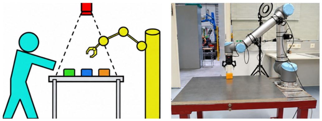
Figure 2.
The UR10 collaborative robot: (left) structure of the UR10, with joints (A) base, (B) shoulder, (C) elbow, (D) wrist 1, (E) wrist 2, and (F) wrist 3; (right) the UR10 in the laboratory workstation.
Figure 2.
The UR10 collaborative robot: (left) structure of the UR10, with joints (A) base, (B) shoulder, (C) elbow, (D) wrist 1, (E) wrist 2, and (F) wrist 3; (right) the UR10 in the laboratory workstation.
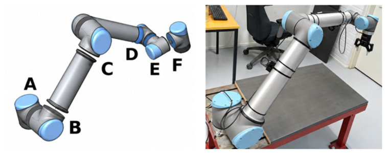
Figure 3.
The Robotiq 2F-85 two-finger adaptive gripper: (a) main components of the gripper; (b) the 2F-85 with its 85 mm stroke; (c) encompassing grip; (d) parallel grip. Adapted from [37].
Figure 3.
The Robotiq 2F-85 two-finger adaptive gripper: (a) main components of the gripper; (b) the 2F-85 with its 85 mm stroke; (c) encompassing grip; (d) parallel grip. Adapted from [37].
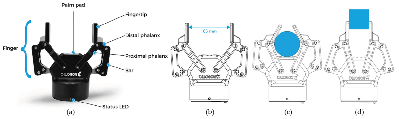
Figure 4.
The SensoPart VISOR V20 robotic vision sensor: (a) front view; (b) rear view; (c) field of view in the x and y directions as a function of working distance for the 8 mm C-mount lens used in this work, calculated from the sensor format (1440 × 1080 pixels, 3.45 µm pixel pitch). Panels (a,b) adapted from [39]; panel (c) calculated from the sensor data in [38].
Figure 4.
The SensoPart VISOR V20 robotic vision sensor: (a) front view; (b) rear view; (c) field of view in the x and y directions as a function of working distance for the 8 mm C-mount lens used in this work, calculated from the sensor format (1440 × 1080 pixels, 3.45 µm pixel pitch). Panels (a,b) adapted from [39]; panel (c) calculated from the sensor data in [38].
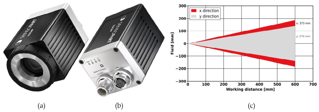
Figure 5.
Structure of the SensoPart VISOR configuration software. SensoFind locates the sensors on the network and launches SensoConfig, for job and detector configuration, or SensoView, for monitoring the running sensor; all three communicate with the VISOR V20 over Ethernet.
Figure 5.
Structure of the SensoPart VISOR configuration software. SensoFind locates the sensors on the network and launches SensoConfig, for job and detector configuration, or SensoView, for monitoring the running sensor; all three communicate with the VISOR V20 over Ethernet.
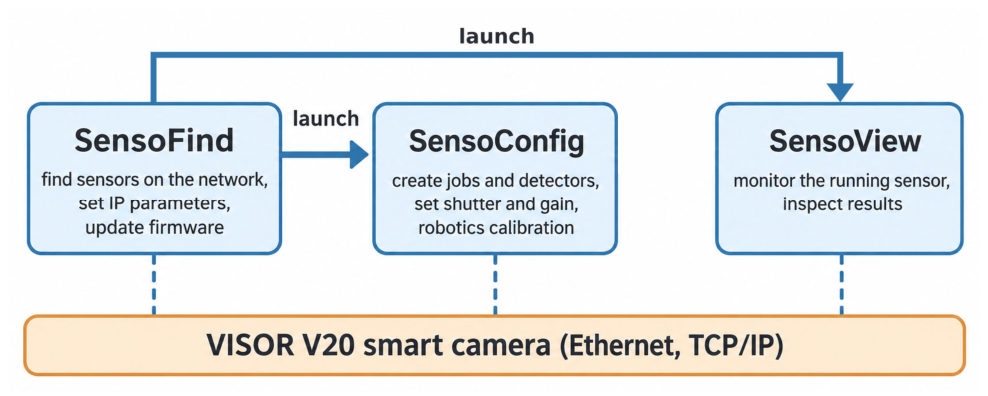
Figure 6.
Calibration of the vision sensor: (a) base coordinate system (Base feature) and (b) tool coordinate system (Tool feature) of the UR robot, adapted from [40]; (c) projection of the camera coordinate system onto the robot coordinate system, adapted from [21] (p. 86); (d) z-shift ΔZ of the measurement plane caused by the workpiece, adapted from [21] (p. 88); (e) successful detection of the calibration plate in the VISOR configuration software during the calibration of this workstation; (f) calibration plate for the VISOR sensor, adapted from [38].
Figure 6.
Calibration of the vision sensor: (a) base coordinate system (Base feature) and (b) tool coordinate system (Tool feature) of the UR robot, adapted from [40]; (c) projection of the camera coordinate system onto the robot coordinate system, adapted from [21] (p. 86); (d) z-shift ΔZ of the measurement plane caused by the workpiece, adapted from [21] (p. 88); (e) successful detection of the calibration plate in the VISOR configuration software during the calibration of this workstation; (f) calibration plate for the VISOR sensor, adapted from [38].
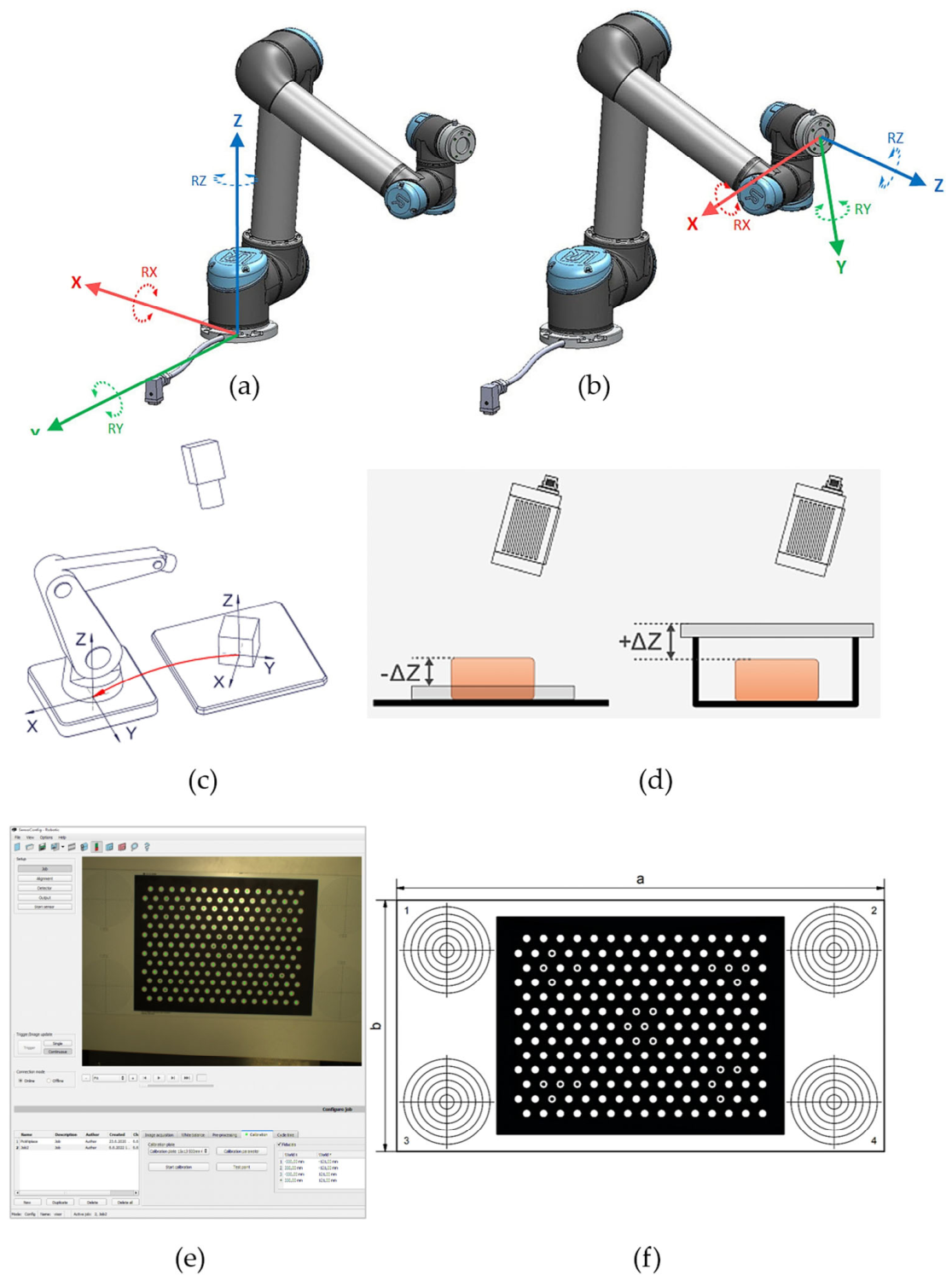
Figure 7.
Physical interconnection of the workstation hardware: the host computer, UR10 controller, and VISOR V20 camera share an Ethernet switch, while the Robotiq gripper is connected to the host through a USB-to-RS-485 adapter.
Figure 7.
Physical interconnection of the workstation hardware: the host computer, UR10 controller, and VISOR V20 camera share an Ethernet switch, while the Robotiq gripper is connected to the host through a USB-to-RS-485 adapter.
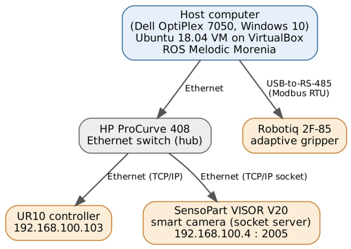
Figure 8.
ROS computation graph of the workstation: detections reach the application node on the /camera_output topic, motion goals are executed through MoveIt and the UR driver, and the gripper is commanded through its action server, which returns results and feedback (dashed).
Figure 8.
ROS computation graph of the workstation: detections reach the application node on the /camera_output topic, motion goals are executed through MoveIt and the UR driver, and the gripper is commanded through its action server, which returns results and feedback (dashed).
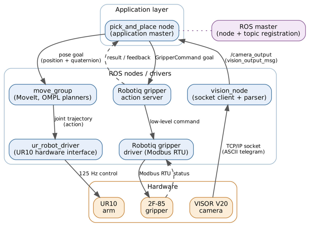
Figure 9.
Euler angles in the x-convention (z–x′–z″ sequence), shown as three successive rotations: D, a rotation by φ about the z-axis; C, a rotation by θ about the new x′-axis (the line of nodes); and B, a rotation by ψ about the new z-axis, corresponding to Equations (2)–(4). Adapted from [42].
Figure 9.
Euler angles in the x-convention (z–x′–z″ sequence), shown as three successive rotations: D, a rotation by φ about the z-axis; C, a rotation by θ about the new x′-axis (the line of nodes); and B, a rotation by ψ about the new z-axis, corresponding to Equations (2)–(4). Adapted from [42].
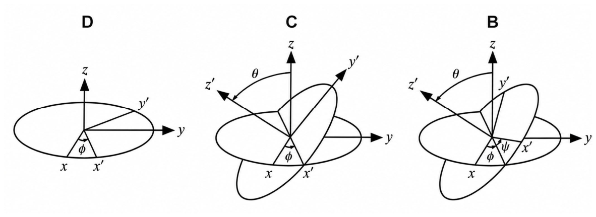
Figure 10.
URDF kinematic tree of the UR10 with the attached Robotiq 2F-85 gripper and the tool-centre-point link (arm_tcp_link) located 171 mm from the flange.
Figure 10.
URDF kinematic tree of the UR10 with the attached Robotiq 2F-85 gripper and the tool-centre-point link (arm_tcp_link) located 171 mm from the flange.
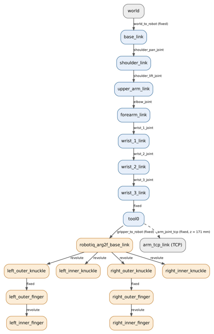
Figure 12.
The MoveIt motion-planning pipeline used in this work. Inside the move_group node, planning request adapters pre-process the pose goal, the selected OMPL planner computes and simplifies a collision-free path against the planning scene, a post-processing adapter adds time parameterisation, and the trajectory is executed through the FollowJointTrajectory action of ur_robot_driver.
Figure 12.
The MoveIt motion-planning pipeline used in this work. Inside the move_group node, planning request adapters pre-process the pose goal, the selected OMPL planner computes and simplifies a collision-free path against the planning scene, a post-processing adapter adds time parameterisation, and the trajectory is executed through the FollowJointTrajectory action of ur_robot_driver.
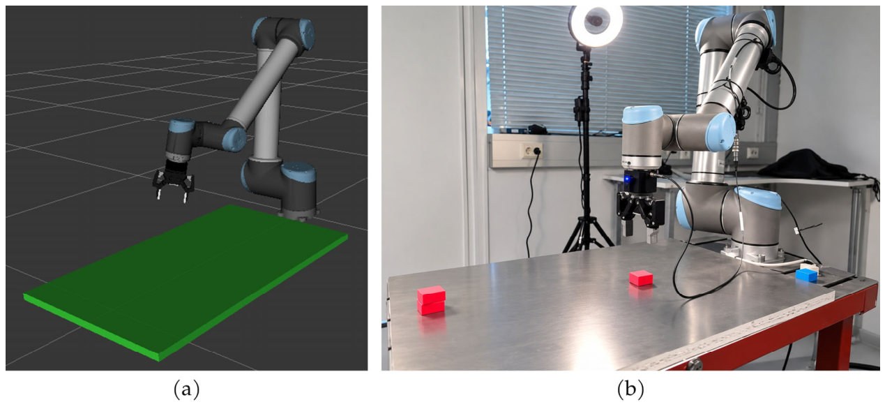
Figure 13.
The UR10 and its collision environment in the MoveIt planning scene, visualised in RViz. The worktable and the two vertical side walls that bound the workspace are modelled as box primitives (green), against which every planned trajectory is checked for collisions.
Figure 13.
The UR10 and its collision environment in the MoveIt planning scene, visualised in RViz. The worktable and the two vertical side walls that bound the workspace are modelled as box primitives (green), against which every planned trajectory is checked for collisions.
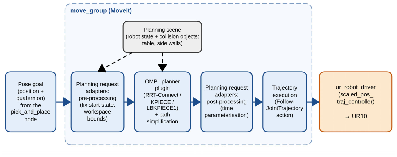
Figure 14.
The start pose (left) and wait pose (right) used in the motion-planning experiment, annotated with the commanded pose goals (position in metres; orientation quaternion with x = 1, i.e., the gripper pointing vertically downwards).
Figure 14.
The start pose (left) and wait pose (right) used in the motion-planning experiment, annotated with the commanded pose goals (position in metres; orientation quaternion with x = 1, i.e., the gripper pointing vertically downwards).
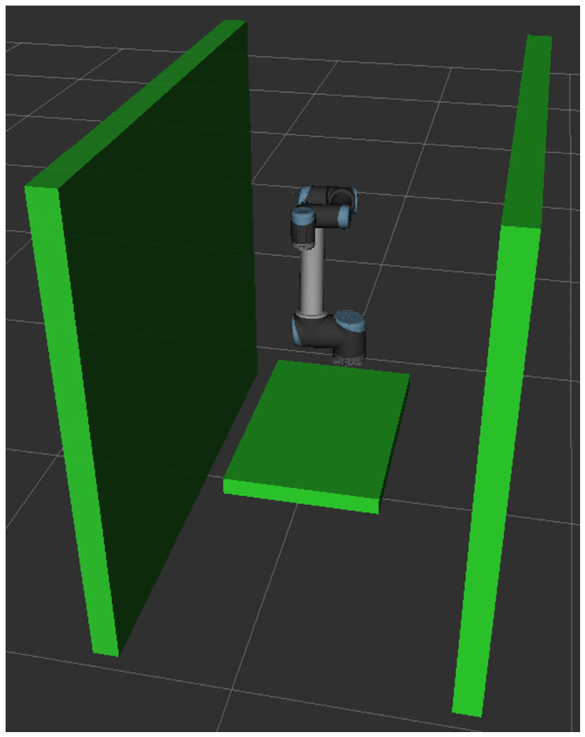
Figure 11.
The UR10 workstation: (a) the UR10 with the attached Robotiq 2F-85 gripper and its planning scene in RViz, with the worktable modelled as a collision object; (b) the physical workstation in the laboratory during autonomous vision-guided pick-and-place operation.
Figure 11.
The UR10 workstation: (a) the UR10 with the attached Robotiq 2F-85 gripper and its planning scene in RViz, with the worktable modelled as a collision object; (b) the physical workstation in the laboratory during autonomous vision-guided pick-and-place operation.
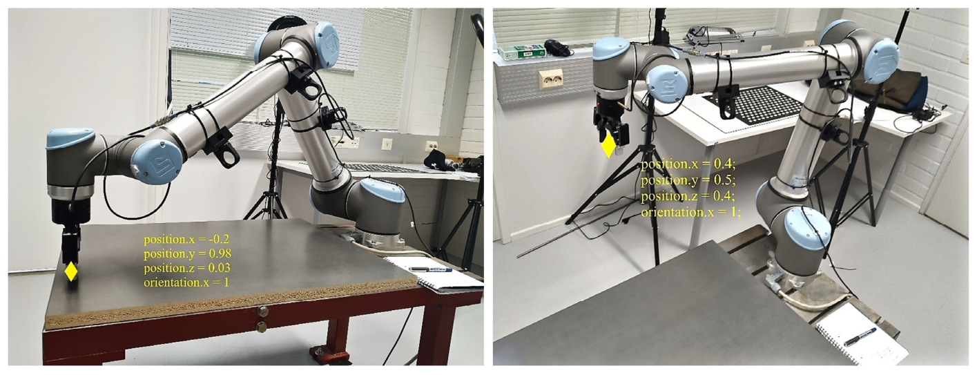
Figure 15.
Control flow of one perception-based pick-and-place cycle.
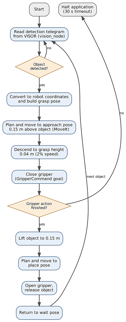
Figure 16.
The collaborative pick-and-place scenario: a human operator working alongside the cobot.
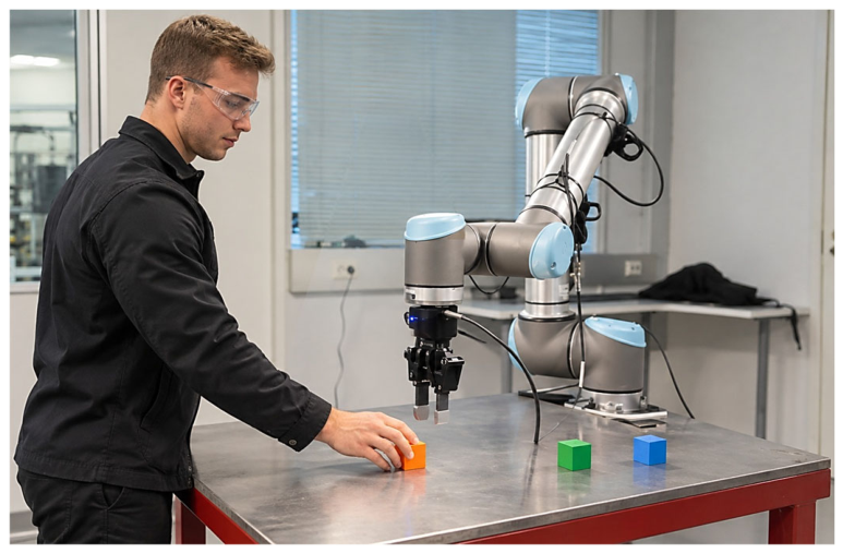
Figure 17.
Successful detection of the object in the VISOR configuration software after configuration and calibration. The located object is enclosed in the green box within the yellow search region, and the result table reports a matching score of 99.1, a position of X = 432.29 mm and Y = 272.61 mm, and an angle of −44.0°. Because the outline of the round part is rotationally symmetric, its angle is defined by the internal features of the taught contour, here the ring of holes, relative to the taught reference.
Figure 17.
Successful detection of the object in the VISOR configuration software after configuration and calibration. The located object is enclosed in the green box within the yellow search region, and the result table reports a matching score of 99.1, a position of X = 432.29 mm and Y = 272.61 mm, and an angle of −44.0°. Because the outline of the round part is rotationally symmetric, its angle is defined by the internal features of the taught contour, here the ring of holes, relative to the taught reference.
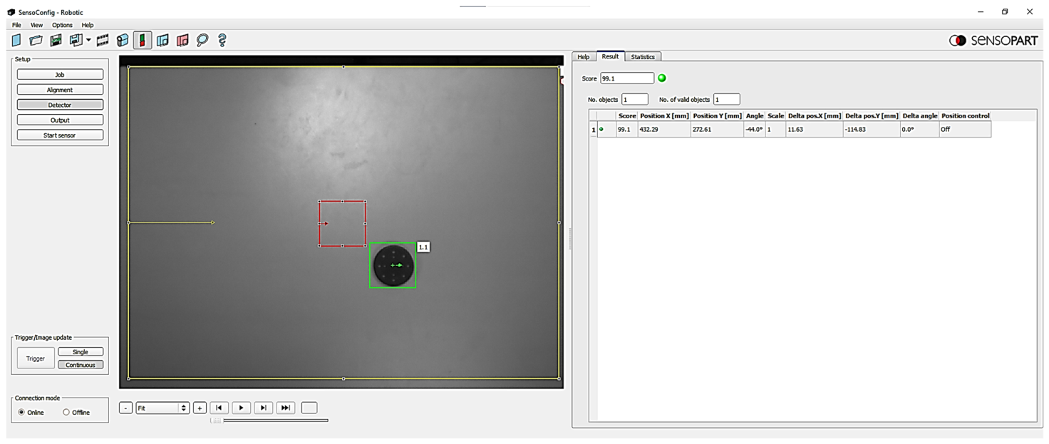
Figure 18.
Planning time (left) and trajectory-simplification time (right) for the RRT-Connect, KPIECE, and LBKPIECE1 planners on the start–wait–start task, for two representative motions (log scale).
Figure 18.
Planning time (left) and trajectory-simplification time (right) for the RRT-Connect, KPIECE, and LBKPIECE1 planners on the start–wait–start task, for two representative motions (log scale).
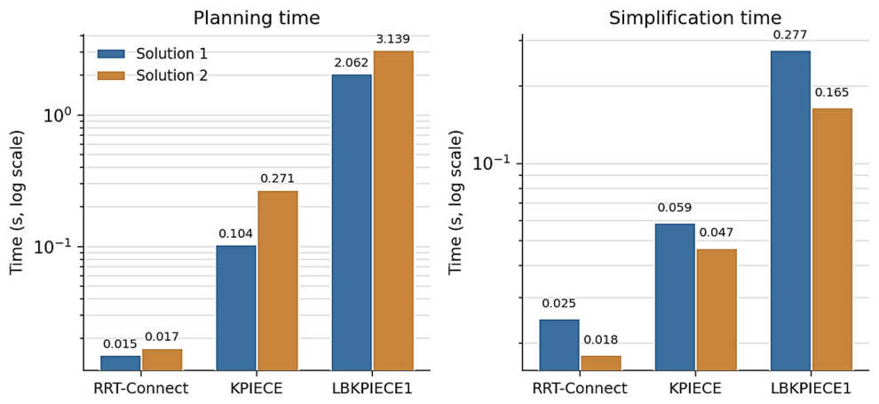
Figure 19.
Calibration accuracy: (left) minimum, mean, and maximum deviation between the entered and recovered fiducials, in millimetres, with the equivalent in pixels at the 0.58 mm/px image scale on the right-hand axis; (right) residual of the plate-grid calibration, in pixels. The maximum fiducial deviation exceeds the 1 mm tolerance associated with high-precision tasks.
Figure 19.
Calibration accuracy: (left) minimum, mean, and maximum deviation between the entered and recovered fiducials, in millimetres, with the equivalent in pixels at the 0.58 mm/px image scale on the right-hand axis; (right) residual of the plate-grid calibration, in pixels. The maximum fiducial deviation exceeds the 1 mm tolerance associated with high-precision tasks.
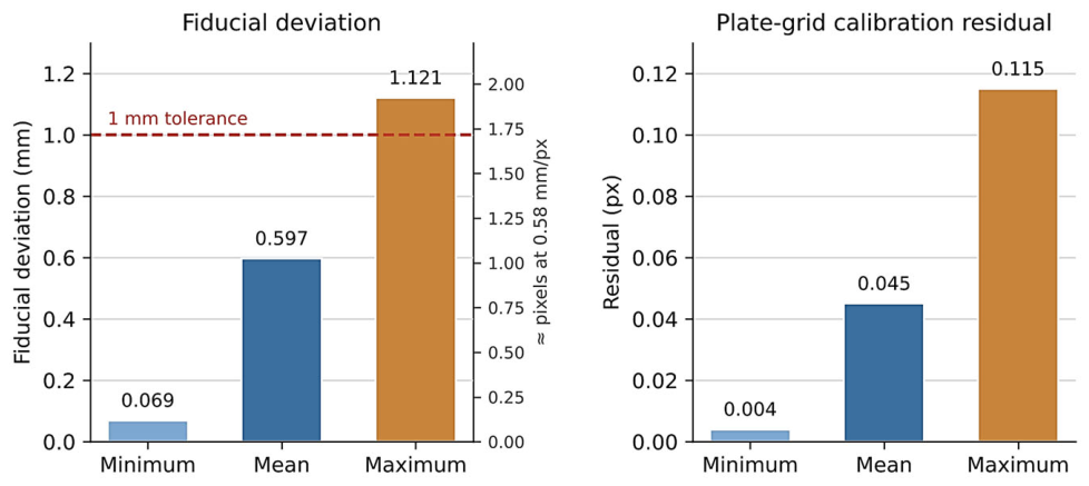
Figure 20.
Runtime ROS computation graph of the case study, redrawn from the rqt_graph output. Ellipses are the active nodes and arrows run from publisher to subscriber, labelled with the topic. Orange: UR driver nodes; blue: ROS and MoveIt nodes; green: the vision, pick-and-place and gripper action-server nodes of the application.
Figure 20.
Runtime ROS computation graph of the case study, redrawn from the rqt_graph output. Ellipses are the active nodes and arrows run from publisher to subscriber, labelled with the topic. Orange: UR driver nodes; blue: ROS and MoveIt nodes; green: the vision, pick-and-place and gripper action-server nodes of the application.
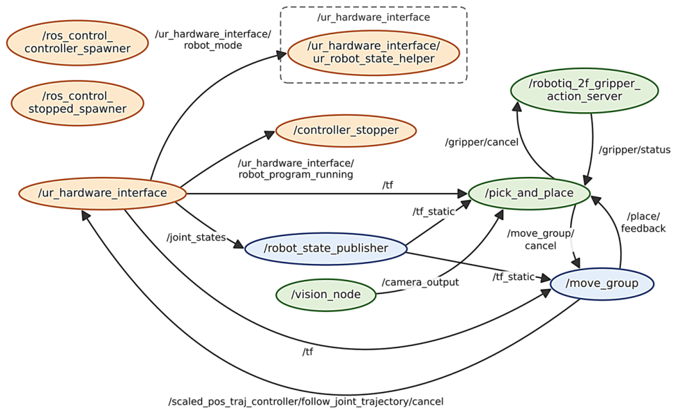

Table 1.
Technical specifications of the UR10 manipulator [35].
Table 1.
Technical specifications of the UR10 manipulator [35].
| Parameter | Value |
| Degrees of freedom | 6 (revolute) |
| Reach | 1300 mm |
| Payload | 10 kg |
| Pose repeatability | ±0.1 mm |
| Weight | 28.9 kg |
| Footprint (base diameter) | 190 mm |
| Joint working range | ±360° (all joints) |
| Maximum joint speed | 120°/s (base, shoulder); 180°/s (elbow, wrists) |
| Typical tool (TCP) speed | 1 m/s |
| Average power consumption | 350 W |
| Communication | 125 Hz control; Modbus TCP, PROFINET, EtherNet/IP, USB |
Table 2.
Representative dashboard-server ASCII commands (port 29999) [36].
Table 2.
Representative dashboard-server ASCII commands (port 29999) [36].
| Command | Function |
| load <name>.urp | Loads the specified robot program |
| play | Starts or resumes the loaded program |
| stop | Stops the running program |
| pause | Pauses the running program |
| robotmode | Returns the current robot mode |
| get serial number | Returns the robot serial number |
| quit | Closes the socket connection |
Table 3.
Technical specifications of the Robotiq 2F-85 gripper [37].
Table 3.
Technical specifications of the Robotiq 2F-85 gripper [37].
| Parameter | Value |
| Stroke | 85 mm |
| Grip force | 20–235 N |
| Payload (form- and friction-fit) | 5 kg |
| Closing speed | 20–150 mm/s |
| Position resolution | 0.4 mm (fingertip) |
| Weight | 0.9 kg |
| Communication protocol | Modbus RTU (RS-485) |
| Parameter | Value |
| Model | V20C-RO-A3-C-2 (Robotic Advanced, colour, C-mount) |
| Resolution | 1440 × 1080 pixels |
| Lens mount | C-mount |
| Image sensor | 1/2.9″ colour CMOS, 3.45 × 3.45 µm pixels |
| Lens | 8 mm focal length (C-mount) |
| Functions | Object detection, measurement, identification, position tracking |
| Capacity | Up to 255 jobs; up to 255 detectors per job |
| Detector types used | Pattern matching, contour |
| Configuration software | SensoFind, SensoConfig, SensoView |
| Interface | Ethernet (TCP/IP socket server) |
Table 5.
Host-computer specifications.
| Component | Specification |
| Model | Dell OptiPlex 7050 |
| Host operating system | Windows 10 Enterprise (64-bit) |
| Processor | Intel Core i7-7700 @ 3.6 GHz (4 cores, 8 threads) |
| Memory | 32 GB RAM |
| Graphics | NVIDIA Quadro P600 |
| Virtualisation | Oracle VirtualBox 6.0.12 |
| Guest OS / ROS distribution | Ubuntu 18.04 LTS / ROS Melodic Morenia |
Table 6.
Fields of the Robotiq 2F-85 gripper output message (six unsigned 8-bit integers).
| Field | Description |
| rACT | Activation bit; activates or resets the gripper |
| rGTO | Go-to bit; commands motion towards the requested position |
| rATR | Automatic release; triggers the emergency auto-release |
| rPR | Position request (0–255); target finger position |
| rSP | Speed (0–255); requested opening/closing speed |
| rFR | Force (0–255); requested grip-force limit |
Table 7.
Vision-calibration parameters and accuracy results.
| Quantity | Value |
| Calibration plate size | 500 × 379.2 mm |
| Lens focal length | 8 mm |
| Calibration mode | Single-image |
| Measurement-plane z-shift | −15 mm |
| Camera height above robot base | 1338 mm |
| Image scale at the working plane | ≈0.58 mm/px |
| Mean fiducial deviation | 0.597 mm |
| Minimum fiducial deviation | 0.069 mm |
| Maximum fiducial deviation | 1.121 mm |
| Mean plate-grid residual | 0.045 px |
| Minimum plate-grid residual | 0.004 px |
| Maximum plate-grid residual | 0.115 px |
Table 8.
Proposed evaluation protocol: performance metrics and the method for measuring each in future quantitative validation.
Table 8.
Proposed evaluation protocol: performance metrics and the method for measuring each in future quantitative validation.
| Performance metric | Measurement method |
| Detection success rate | Successful detections / total attempts |
| Grasp (pick) success rate | Successful grasps / pick attempts |
| Placement success rate | Correct placements / place attempts |
| Mean cycle time (s) | Detection-to-release time, averaged over trials |
| Mean / maximum localization error (mm) | Detected vs. ground-truth object position |
| Mean / maximum placement position error (mm) | Achieved vs. target placement position |
| Mean / maximum placement orientation error (deg) | Achieved vs. target placement orientation |
| Object geometries tested | Object shapes used (e.g. block, cylinder, irregular) |
| Number of trials | Total pick-and-place cycles executed |
Table 9.
Comparison of approaches for integrating a smart camera into a robotic cell, by whether each is ROS-native, independent of the camera vendor’s SDK, preserves task autonomy, and is reusable across different cameras.
Table 9.
Comparison of approaches for integrating a smart camera into a robotic cell, by whether each is ROS-native, independent of the camera vendor’s SDK, preserves task autonomy, and is reusable across different cameras.
| Approach | ROS-native | Vendor-indep. | Autonomy | Reusable |
| Manual entry / taught points | n/a | Yes | No | n/a |
| Vendor URCap (teach pendant) | No | No | Yes | No |
| Open-source ROS camera driver | Yes | Partly | Yes | No |
| OpenCV pipeline on raw stream | Yes | Yes | Yes | Partly |
| Socket client + message (this work) | Yes | Yes | Yes | Yes |
Disclaimer/Publisher’s Note: The statements, opinions and data contained in all publications are solely those of the individual author(s) and contributor(s) and not of MDPI and/or the editor(s). MDPI and/or the editor(s) disclaim responsibility for any injury to people or property resulting from any ideas, methods, instructions or products referred to in the content. |
© 2026 by the authors. Licensee MDPI, Basel, Switzerland. This article is an open access article distributed under the terms and conditions of the Creative Commons Attribution (CC BY) license (http://creativecommons.org/licenses/by/4.0/).
Copyright: This open access article is published under a Creative Commons CC BY 4.0 license, which permit the free download, distribution, and reuse, provided that the author and preprint are cited in any reuse.