

Submitted:
12 November 2026
Posted:
16 November 2026
You are already at the latest version
Abstract
The lunar environment imposes challenging conditions for the generation and storage of electrical power that will be essential to support any lunar infrastructure, both human and robotic. In particular, lunar industrialisation will be required for permanent human occupation and to support the growth of robotic assets on the Moon, though it is worth noting that universal construction does not require a human presence. Nuclear reactors are an obvious solution but transport from Earth to the Moon is expensive as lunar infrastructure grows. We review the state-of-the-art of terrestrial and space nuclear reactors and find that advanced technology based on exotic materials to enhance reactor efficiency are not compatible with lunar reactor production where material resources are restricted. We then examine how nuclear reactors may be constructed from lunar resources within a set of constraints imposed by lunar industrial capabilities. We suggest that Magnox nuclear reactors, although a mature technology, are a practical possibility that may be leveraged and fuelled from lunar resources. From the vantage of the Moon, Magnox reactors may be married to water-propelled or Mg-propelled Hall effect thrusters, also manufactured and fuelled from lunar resources, opening up access to nuclear-electric propulsion (NEP) technology constructed in-situ.
Keywords:
in-situ resource utilisation
; lunar resources
; lunar nuclear reactors
; magnox reactor
; nuclear-electric propulsion
1. Introduction
IN-SITU resource utilisation (ISRU) will be essential to realise permanent settlement of the Moon and the required infrastructure to support it. We assume that there is a minimum degree of industrial capacity that can implement a lunar industrial ecology [1,2] to exploit lunar resources and has the adaptability to implement universal construction [3]. We regard this as essential for supporting any major, permanent lunar infrastructure. The two-week lunar night presents challenges for power generation/storage on the Moon. It is desirable that the power infrastructure is leveraged from lunar resources. Solar concentrators with thermionic conversion and flywheel energy storage offer alternative and superior options to traditional photovoltaic and chemical battery solutions [4]. Flywheels do not exhibit diminishment of depth of discharge and the adoption of magnetic bearings in flywheels eliminates frictional discharge. Both photovoltaics and thermionics, however, require energy storage for two weeks that must be charged up during the two-week day in addition to supplying their loads. Extensive electrical power will be required during the lunar night to support lunar habitats [5] and robotic industrialisation [6]. At current Astrobotic published prices to land a payload onto the Moon of $1.2M/kg, a 100 kWe nuclear reactor with a specific power of 20 W/kg would cost $6B to deliver its 5 tonnes to the Moon. Even with a potential order of magnitude reduction in delivery cost to $100,000/kg, this amounts to $600M for just 100 kWe to supply one lunar base. To that end, we explore the construction of nuclear reactors on the Moon from in-situ resources. We also explore the construction of ion engines from lunar resources. Such nuclear power sources can be exploited by ion engines similarly constructed from in-situ resources, i.e. the manufacture of nuclear-electric propulsion (NEP) systems from lunar resources would be a test of the universal construction capability of the lunar industrial ecology. As we are focused on ISRU, we concentrate on assessing lunar resource availability and assume that a significant lunar industrial ecology is in place [2,7], suggesting that lunar resource-based nuclear reactors represent a generational step in lunar industrialisation. We acknowledge that the lunar environment poses extreme environmental conditions for all industrial operations including wide temperature variations and dust mitigation but we do not address these here.
The dominant minerals on the Moon are plagioclase feldspar (dominantly anorthite CaAl2Si2O8), pyroxene (such as augite (Ca,Fe,Mg,Ti,Al)2Si2O6), olivine (dominated by forsterite Mg2SiO4), ilmenite (FeTiO3) and spinel (dominated by MgAl2O4 but include minor amounts of other minerals such as chromite FeCr2O4) [8], all of which may be exploited as resources. The highlands are dominated by anorthosites while the mare are dominated by basalts classified according to their TiO2 content as ilmenite. There are components that are poorly represented on the Moon such as Na, Cl, Cu, Zn, Pb, etc so it will be necessary for material substitutions to leverage nuclear technology from lunar resources as terrestrial nuclear reactors represent highly engineered systems. However, the natural palaeo-reactor at Oklo represents the simplest architecture that formed a pressurized water reactor (PWR) through natural geological processes [9]. For example, Stirling or Brayton cycle power conversion is commonly adopted for thermal-to-electric conversion but thermionic conversion is also viable to eliminate moving parts [4] (though controls rods still require actuation) but this is only feasible for high temperature reactors. A useful source of lunar elemental abundances is given by [10] for which we list the most abundant as theoretical oxides (Table 1).
The lunar industrial ecology can accommodate most of the required material substitutions for a lunar-derived nuclear reactor [1,2]. This is based on a generalised manufacturing chain comprising a sequence of operations constrained into a bow-tie architecture [3]. Comminution and beneficiation are based on ball milling and electromagnetic/electrostatic separation respectively. Chemical processing is based on HCl leaching of anorthite and orthoclase, hydrogen reduction of ilmenite, hydration of olivine and carbonyl refinement of asteroid-derived Fe, Ni and Co. HCl leaching requires the import of NaCl reagent which is recycled rather than consumed. Silica, alumina and titania ceramics provide non-metal functions. These and further chemical processes form a near-closed loop ecology in which the waste of one process is feedstock for other processes [1,2]. Following separation into pure oxides, reduction is accomplished through molten salt electrolysis into near pure metal powders [11]. Metal powders are mixed to form a diverse range of metal alloys for 3D printing into structures using selective laser sintering, electron beam additive manufacturing and selective solar sintering. Systems are then assembled robotically using reconfigurable manipulators [12]. We focus specifically on material resources and chemical processing and do not cover parts and component manufacturing aspects of nuclear reactors or electric propulsion systems.
2. Nuclear Fissile and Fertile Fuels
Nuclear reactors operate through a neutron-induced chain reaction of a fissile material such as 235U or 239Pu. High resolution mapping of lunar U (1764.5 keV) and Th (2614.5 keV) gamma rays have revealed an average ~0.3 ppm U (with large variations of up to 2 ppm especially at Procellarum KREEP basaltic terrane (PKT)) and ~1-2 ppm Th (with large variations of up to 7 ppm at PKT) and average U/Th ratio of 0.27 similar to that of chondrites (~0.28) [13]. Change-2’s gamma ray spectrometer’s measurements of Th abundance yield higher concentrations in the eastern highlands than the western highlands, especially within the Imbrium basin at PKT at >3 ppm and high concentrations up to 7.5 ppm Th due to the Fra Mauro Highlands [14]. More recent assessment suggests 8-12 ppm in highland regions of PKT [15]. Other elevated Th abundances occur at SPA near the Ingenii basin with 3.5 ppm (compared with diminished abundance of ~1 ppm in feldspar-dominated highland terrain) and an anomaly in the farside highlands at the Compton-Belkovich region with 9 ppm [16]. There may be much higher local concentrations of Th.
U and Th are associated with KREEP minerals. Thorium mapping yields a ring around the Imbrium basin on the nearside with estimated concentration close to terrestrial rare earth element (REE) ores. There are several regions of the Moon enriched in KREEP elements which can be traced through thorium measurements – Oceanus Procellarum and Mare Imbrium on the nearside and the South Pole-Aitken Basin. REE in lunar KREEP deposits under Oceanus Procellarum and the Imbrium Basin have abundances of 180 ppm Nd and 65 ppm Dy [17]. They resemble their terrestrial counterparts but often with substitutions – apatite (Ca5(PO4)(F,Cl)), merrillite (Ca17.3Y0.4(La-Lu)0.88(Mg,Mn,Fe)2.4(Na,K)0.07(P,Al,Si)13.9O56), monazite ((REE,Th,Ca,Sr)(P,Si,S)O4), xenotime ((REE,Zr)(P,Si)O4), yttrobetafite (Ca,Y,U,Th,Pb,REE)2(Ti,Nb)2O7 up to 9.45% Y) and tranquillityite (Fe8(Zr,Y)Ti3Si3O24 up to 4.6% Y and 0.25% Nd) [18]. Apatite, merrillite and monazite are the commonest rare earth sources and are found in association with each other in all KREEP deposits. Phosphates (apatite, whitlockite and merrillite) in stony meteorites as carriers of REE are depleted in REE compared with the Moon. KREEP minerals are enriched in U and Th – in yttrobetafite, U is in 38,200 ppm concentrations. Assuming a common terrestrial isotopic ratio 235U/238U ~0.72%, lunar U resources yield a 235U peak concentration of 0.014 ppm. Oceanus Procellarum exhibits around ~10 x 10-6 g/g of Th [19]. South Pole Aitken basin has slightly elevated in K and Th compared with the rest of the Moon [20]. Chang’e 5 (2020) successfully returned samples from the 2 Byr old Oceanus Procellarum KREEP basalts confirming their enrichment in REE and radioactive U and Th [21]. To release REE, apatite may be initially rapidly leached with 1.0M HCl followed by a 2.0M HCl leach with near 100% efficiency (it is more efficient to acid leach in two stages [22]):
Ca10(PO4)6F2 + 20HCl → 6H3PO4 +10CaCl2 + 2HF
This separates Ca from monazite which may be treated with hot 60-75%% concentrated alkali NaOH at 140oC:
(REE)PO4 + 3NaOH → (REE)(OH)3 + Na3PO4
The resultant solid solution hydroxide washed with hot water to remove soluble phosphates and excess alkali. The remainder (REE)(OH)3 is dissolved in HCl with 90% REE recovery:
Ca(OH)3 + HCl → (REE)Cl3 + 3H2O
Separation of the mixed REE chlorides in solution is too complex [23] to undertake on the Moon.
U may be mined, crushed in a ball mill and mixed with water. Although HCl can be used to extract U from merrillite or yttrobetafite, it requires more complex and inefficient chemical processing. U may be extracted using the stronger H2SO4 acid to dissolve U at 50-90oC, mixed with H2O2 oxidiser followed by addition of Na2CO3 to precipitate the U compound. The liquid is dried to yield predominantly U3O8 (yellowcake). This is calcined at 800oC with H2 to yield UO2. Ceramic fuels do not melt so UO2 may be supplemented by inert matrices such as cercer (SiC, ZrC, MgO, etc) and cermet (W, Mo, etc) to raise temperature tolerance. High temperature W-UO2 cermet comprises 20% UO2 fuel pellets within a W metal matrix stable to temperatures up to 2000oC [24]. Given terrestrial isotopic ratio 235U/238U ~0.72%, lunar U resources yield a 235U peak concentration of 0.014 ppm which must be enriched using high speed gas centrifuges in UF6 form. This requires hydrofluorination of UO2 with HF gas and then F gas. The F content of lunar soil (except anorthosites) is similar to that of C1 chondrites at ~60-70 ppm but other halogens such as Cl vary widely [25]. Although fluorapatite Ca5(PO4)3F and the even more scarce chlorapatite Ca5(PO4)3Cl occur on the Moon, they are both scarce in relation to other more accessible minerals. Hence, F is rare on the Moon and would require import from Earth and HF acid is dangerous. Cl is not a feasible substitute as UCl4 is a solid and Cl abundance on the Moon is low ~20 ppm [26]. Enriched UF6 is reacted with H2O to yield hydrated UO2 which is reduced by H2 to U metal. UCx to prevent swelling becomes feasible if significant C resources are located [27,28]. Clearly, gaseous enrichment and UF6 liquid thermal diffusion are infeasible.
The abundance of thorium on the Moon offers the most obvious nuclear fuel by mining ThO2 and transmuting it to fissile uranium [29]. Natural Th is almost 100% fertile 232Th isotope with a half-life of 14 By. Th may be extracted chemically from monazite (RE/U/Th)PO4 with a yield of 6-7% Th which is ground, followed by a series of treatments to precipitate out thoria ThO2 [29]. This requires dissolution in NaOH at 400-500oC followed by treatment with hot concentrated HCl to dissolve rare earths. Th(OH)4 is precipitated and calcined at 900-1000oC into ThO2. NaOH and HCl reagents are already incorporated into the lunar industrial ecology. ThO2 may be fabricated into fuel pellets or mixed with UO2 or PuO2 neutron sources - 232Th must undergo slow neutron irradiation to decay into 233U:  . This is a breeding process that occurs over 30 days using a slow neutron thermal reactor with a neutron moderator. The thorium cycle reduces radioactive waste toxicity.
3. Terrestrial Nuclear Reactors
A terrestrial nuclear reactor comprises several parts - its particulate fuel packed within fuel rods, a neutron reflector (commonly Be or BeO), control rods (commonly B4C) with high neutron capture cross section to absorb neutrons and control the reaction rate, neutron moderator (such as ZrH) to slow fast neutrons into thermal neutrons, coolant fluid (most commonly water but liquid Na or He-Xe are options) to transfer heat out of the reactor core, radiation shielding (commonly LiH for neutrons and W for gamma rays), heat pipes with high temperature corrosion resistance (such as Hastelloy alloy) with high temperature thermal radiator (Ti alloy), the heat exchanger to drive a turbine and a containment vessel (typically concrete). Typically, heat generated through nuclear fission is transmitted through a working fluid that turns turbines to generate electricity. Forms of corrosion include embrittlement and dissolution due to oxidation, carburisation and decarburisation by coolant impurities. A review of materials suitable for different nuclear reactors has been presented in [30]. A small ~10 kW nuclear reactor such as the Pylon reactor may potentially be leveraged from lunar resources given certain constraints assuming that even rarified elements can be recovered [31]. Nuclear fuel is typically enriched fissile 235U though there are reactors that do not require it. The pressurised heavy water reactor (PHWR) such as CANDU is similar to the PWR but uses heavy water (D2O) as moderator but light water as coolant. Graphite and heavy water moderation allows the use of unenriched fuel. CANDU reactors are fuelled with fertile 238U which is converted to fissile 239Pu by the extra neutrons of the heavy water moderator. The commonest fuel is UO2 ceramic packed into fuel rods with cladding to provide a corrosion-resistant barrier between coolant and fuel rods. Control rods are inserted into the nuclear reactor core to control the rate of chain reaction by absorbing neutrons. A neutron reflector is a surrounding reactor envelope that increases the efficiency of neutron chain reaction. A neutron moderator reduces the speed of fast neutrons to thermal neutrons to increase neutron capture for fission.
Almost 90% of global nuclear energy is generated by pressurised water reactors (PWR) and boiling water reactors (BWR) which exploit water as both coolant and moderator [30]. Such light water reactors (LWR) operate at ~300oC. Fuel rods are bundles of tubes that typically comprise UO2 ceramic packed in Zr alloy cladding with He gas filling the fuel-cladding gap to improve heat conduction. Control rods are Hf or Cd to absorb neutrons in hot water moderation reactors. In the BWR, the reactor boils coolant water directly in the reactor core which is also used to drive turbines; in the PWR, water for cooling the reactor and pressurised steam for driving the turbines are in separate loops. Water also acts as a neuron moderator in decelerating fast neutrons into thermal neutrons increasing their reaction cross section which requires the use of low-enriched fuel with 3% 235U. Due to the corrosivity of high temperature water of the PWR, they are encased in a Mn-Mo-Ni steel reactor vessel internally lined with stainless steel. Stainless steel was also used for all piping and valves. Enhanced corrosion resistance is exhibited by Ni-Cr-Fe steel alloy 690 [30]. Zr alloy exhibits neutron transparency so zircalloy-4 is used as the cladding material. Small modular reactors are commonly PWRs offering 5-100 MWe or more per module. They are typically pebble bed reactors (PBR) which use fuel in ceramic ball form. They do not use moderators and absorb fast neutrons. Fast neutrons require more highly enriched fuel ~20% 235U or bred 239Pu. This requires the use of gas centrifuges to increase natural 235U concentration from 0.7%. This is undesirable as it requires complex infrastructure.
Molten salt reactors use low-mass salts – fluorides or chlorides of Li or Be – as coolant mixed with dissolved UF4 or ThF4 fuel with graphite or BeO moderator [30]. Potentially, UF4 may be replaced with U3Si2 which is an accident tolerant fuel. A molten Pb salt tolerates up to 1500oC as well as acting as shielding. A liquid salt fluoride Th reactor is a thermal breeder reactor in which 232Th and 233U are dissolved in molten fluoride salt. Molten salt reactors operate at 700-1000oC and are highly corrosive requiring high Ni-content alloys such as Hastelloy-N (22% Cr, 9% Mo, 18% Fe, 49% Ni, 1.5% Co and 0.5% W), MA-ODS (75% Fe, 20% Cr, 0.5% Ti, 4.5% Al, 0.05% C and 0.5% Y2O3) steel and Mo TZM (99.37% Mo, 0.1% Zr, 0.5% Ti and 0.03% C) alloys for corrosion resistance up to 700oC. Haynes alloy constituents are 65% Ni, 20% Cr, 13% W, 1% Mo, 0.25% Si, 0.2% Al and other traces. Although Ni, Cr, Si and Al may be sourced on the Moon, the other constituents cannot. Hastelloy is a family of corrosion-resistant Ni-Cr-Mo alloys that can tolerate acids and oxidants at high temperature and pressure.
Liquid alkali metals may be used as high-power density coolants – Na (e.g. TOPAZ), NaK (77% K and 23% Na, e.g. SNAP-10A) – and possess low moderator effects for fast neutron reactors [30]. They are liquid at low temperature and have usually been adopted in fast reactors. If corrosive F salts are avoided, Hastelloy alloys may be substituted with steels. The high power density of liquid metals provide for compact designs suitable for submarines and spacecraft. The reactor operating temperature is limited only by the boiling point of the metal. NaK eutectic alloy is liquid at room temperature (boiling point of 785oC so it is limited to 550oC with margin) but Na alone requires heating to 98oC to be molten (boiling point of 883oC). Na and NaK are also explosively reactive with water but do not corrode steel. Liquid metal reactors generally employ 316 stainless steels (15 Cr – 15 Ni - Ti) for reactor vessel, pipework, pumps and cladding. Liquid Na could be employed as a coolant due to recent discoveries that the average lunar Na abundance is 1.33% by weight [32]. However, this is still a modest abundance compared with bulk abundances of Fe and even water ice at the lunar poles. The molten salt and liquid metal reactors require non-available bulk material so must be excluded from consideration.
4. Space Nuclear Reactors
Historically, US efforts in space nuclear reactors have been modest compared with Russia - the Soviet Union launched 33 nuclear reactor-powered satellites over 1967-1988. High temperatures ~550-1000oC for maximizing efficiencies impose material selection requirements for space reactors [33]. SNAP (systems for nuclear auxiliary power)-10A was a 290 kg nuclear reactor with a power output of 30 kWth/500 We launched in 1965 that functioned for 43 days until an electrical failure occurred. It comprised 37 fuel rods of highly enriched 235U mixed with a ZrH moderator. It used molten NaK alloy as a coolant through the core to operate at ~500-1000oC for maximum efficiency. Be reflectors surrounded the reactor. Electrical conversion was by SiGe thermoelectric converters with <2% efficiency to minimise moving parts. The SP-100 developed over 1983-1994 was similar with highly enriched 235U at an operating temperature of ~1000oC with thermoelectric converted power output of 100 kWe but was cancelled. The TOPAZ (thermionic operating reactor active zone) II nuclear reactor had some similarities with SNAP-10A. The 320 kg TOPAZ had a power output of 100 kWth/5 kWe that was launched in 1987 and operated for 54 days. It comprised 37 fuel rods of 96% enriched 235UO2 fuel mixed with ZrH moderator. It used molten Na alloy as a coolant through the core while Be reflectors surrounded the reactor. It adopted thermionic conversion at 1200 K using W/Mo cathodes that emitted electrons and Nb/Mo anodes to collect electrons within a Cs vapour offering an efficiency of 5%. Following an extensive review of materials, a high performance fast micro-reactor was deemed to require exotic materials such as UN for fuel, Pb for coolant and Mo alloy for structure [33] but such materials cannot be readily sourced from the Moon.
Several electrical conversion methods may be explored for space nuclear reactors [34]: (i) SiGe thermoelectric conversion based on the Seebeck effect with 6-7% conversion efficiency for liquid metal cooled space reactors using molten K heat pipe radiators; (ii) alkali-metal thermal-to-electric conversion (AMTEC) using Na or K working fluid with 25% efficiency for liquid metal cooled space reactors using molten K heat pipe radiators; (iii) Brayton cycle using Xe/He working fluid with an efficiency of 21%; (iv) Stirling cycle energy conversion offers the highest efficiencies of 30%. The Brayton cycle working gas may also be CO2. Kilowatt reactor using Stirling technology (KRUSTY) is a 1 kWe fission power test that may be expanded to 10 kWe as the basis of a modular planetary surface nuclear reactor [35]. It successfully tested a stainless steel reactor with a monolithic U-Mo fuel unit at 800oC coupled to a Haynes 230 heat pipe carrying molten sodium to a pre-existing Stirling engine energy converter. Four such modules could supply the 40 kWe lunar nuclear fission system required to support a lunar base.
Rather than SiGe thermoelectric material, magnesium silicide (Mg2Si) is thermoelectric and can be sourced on the Moon. Both MgO derived from olivine and SiO2 from silicate may be reduced to their respective metals through molten salt electrolysis [11]. Mg2Si may be formed through heating Si and Mg in the absence of oxygen. Alternatively, SiO2 reacts exothermically (thermite) with excess Mg which eliminates the SiO2 reduction step: SiO2+4Mg → 2Mg2Si +2MgO. Mg2Si is a thermoelectric material which may be n-doped with Al by ball milling with >2% Al then mixed with 0.25% conductive glass (Mg-Si-B-Ca) frit sintered at 1123 K to fill Mg2Si cracks to reduce its brittleness [36]. We may estimate the thermoelectric performance through the parameter ZT:
(1)
where S=Seebeck coefficient, σ=electrical conductivity, T=absolute temperature, K=thermal conductivity. This correlates to thermal conversion efficiency:
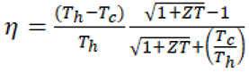 (2)
If Tc=300 K and Th=800 K with ZT~1 for Mg2Si theoretically yielding η=14% theoretically. More realistically, Mg2Si has ZT=0.3-0.6 at 500 K increasing to ~0.8 at 700 K so this requires high temperature operation. In reality, η~10% is typical of Mg2Si at 800 K so this offers poor conversion efficiencies. The longevity of Mg2Si thermoelectric converters over decades is also unproven. AMTEC uses a thin Na-β-alumina solid electrolyte (BASE) membrane with a spinel crystal structure that minimises electron conductivity while maximising ionic conductivity. Diffusion of alkali metal ions (Na or K) of the working fluid from the anode side to the cathode side is accompanied by electron flow through an external circuit from the anode to the cathode. It requires Mo-Re structure to prevent corrosion by the working fluid. Although AMTEC offers the highest conversion efficiency, advanced thermionic conversion offers still higher conversion efficiencies [37]. To prevent a reactor from overheating, multiple fins provide large surface area from which to radiate heat to space. The constraints for space nuclear reactors were compactness but for in-situ resourced lunar nuclear reactors, the constraint is material availability. In-situ resources effectively remove launch mass and payload fairing volume constraints.
5. Gas-Cooled Nuclear Reactors
Gas-cooled reactors offer the prospect of high temperatures beyond water-cooling (up to 300oC) though less than liquid metal (up to 540oC) for thermal efficiency [38]. The higher temperatures with gas-cooling allow integration with high conversion efficiency gas cycles such as the Brayton cycle. Magnox and advanced gas cooled reactor (AGR) use graphite as a moderator but CO2 gas as a high-pressure coolant. The hot CO2 is pumped at 25+ bar through a heat exchanger to generate steam for driving a turbine. CO2 is used to prevent oxidation of the graphite moderator that would result with using air. CO2 coolant tend to degrade to CO at high temperature which erodes the graphite moderator. The addition of CH4 reduces this. Although carbon is scarce on the Moon ~100 ppm in the regolith, it is potentially available in carbonaceous chondrites on the Moon [27,28].
High temperature gas-cooled reactors (HTGCR) typically comprise either a prismatic block or pebble beds of graphite which act as moderator, reflector and the core of the reactor. HTGCR at 700-1000oC use He coolant circulating through coolant holes in the graphite core or through the interstices between pebbles. He coolant is a better thermal conductor than CO2. Noble gases such as He have abundances considerably less than H and C in lunar regolith [39]. HTCGR can burn Th as well as U in ceramic form, typically as TRISO (tri-structural isotropic) fuel particles of UO2 surrounded by C and SiC for thermal stability [40]. This retains radionuclides within the fuel particles without additional boundaries. Candidate reactor vessel materials include 304 stainless steel, 316 stainless steel, 2.25 Cr – 1 Mo ferritic steel, high-Ni 617 alloy steel and Hastelloy-XR [30]. Low activation materials are tolerant of radiation exposure but must be of high purity – 7-9 Cr-W-V-Ta ferritic-martensite steel (up to 500oC), Ti-5Al-2.4V with Cr2O3+SiO2 or TiO2 coating (up to 500oC) and SiC fibres reinforced SiC ceramic composite [41]. Ceramics such as SiC fibres in SiC matrix have demonstrated promise at high temperatures up to 1200oC. Higher temperatures permit the use of more efficient Brayton cycle rather than the Rankine cycle. The Rankine cycle with a K-based fluid yields only 20% efficiency for 2 MWe. A modular very high temperature gas-cooled reactor at can generate up to 100 MWth/m3 [38]. HTGCR is not feasible for a lunar nuclear reactor design due to its dependence on high performance materials that cannot be readily sourced on the Moon.
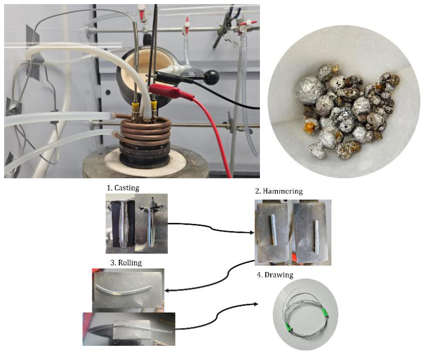
The Magnox reactor uses fuel rods of natural uranium 238U metal rather than U3O8 ceramic (yellowcake) so no enrichment is required. Alternatively, cermet fuel may be employed as UO2 in an MgO matrix. Given Magnox alloy’s reactivity with water, spent fuel rods cannot be deposited into cooling ponds but may be buried under regolith. The fuel rods are finned to improve heat transfer to the coolant. The Magnox reactor uses a CO2 gas coolant at 4.3 MPa pressure with a maximum operating temperature of <450oC imposed by the cladding tolerance. The thermal efficiency of the Magnox reactor is 25-30% using the CO2 Brayton cycle [42]. Heating the organic fraction of carbonaceous chondrites at 700oC will release organic volatiles that may be oxidised in O2 to CO2 and water. The fuel rods are clad within Mg-0.8Al-0.004Be (magnesium non-oxidising) alloy embedded in graphite bricks acting as the neutron moderator. Mg has a low neutron absorption cross section while Be reduces the tendency to oxidation – the 0.004% Be may be omitted because it serves to reduce oxidation sensitivity which may be counteracted by adding small amounts of CH4 into the coolant to prevent CO production – CH4 may be generated from CO2 at 400oC through the Sabatier reaction with an Ni-on-alumina catalyst as often proposed for Mars (CO2 + 4H2 → CH4 + 2H2O) [43-33]. For the cladding, lunar forsterite may be treated with HCl acid leaching which is tolerant to impurities: Mg2SiO4 + 4HCl + 4H2O → 2MgCl2 + H4SiO4. Silica may be precipitated from silicic acid H4SiO4. MgCl2 may be treated with NaOH: MgCl2 + 2NaOH → Mg(OH)2 + 2NaCl. Mg(OH)2 heated to 600-800oC yields MgO: Mg(OH)2 → MgO + H2O. MgO may be reduced directly into Mg metal through molten salt electrolysis [11-9]. Al may be sourced and extracted from lunar anorthite through HCl acid leaching [44] (Fig 1) followed by molten salt electrolysis [45] (Fig 2). These demonstrations processing LHS-1 (74.4% anorthosite, 24.7% basalt, 0.4% ilmenite, 0.3% olivine and 0.2% pyroxene) lunar highland simulant through a series of steps: (i) simple magnetic beneficiation to remove the unwanted iron-containing fraction; (ii) HCl leaching to yield calcium chloride solution (for replenishment of CaCl2 molten salt electrolyte), silica (for use as fused silica glass and quartz) and hydrated aluminium chloride CaAl2SiO8 + 8HCl + 2H2O → CaCl2 + 2AlCl3.6H2O + 2SiO2; (iii) heating hydrated aluminium chloride to yield alumina, water and partially recycled HCl solution: 2AlCl3.6H2O → Al2O3 + 6HCl + 9H2O; (iv) reduction of alumina into 95% pure Al metal using molten salt (CaCl2) electrolysis which was subsequently drawn into wire to demonstrate its utility. This yielded a recovery fraction of 11% Al metal from LHS-1 compared with a theoretical fraction of 14%.
Figure 1.
(a) beneficiation; (b) post-leaching; (c) dried silica; (d) dried alumina.
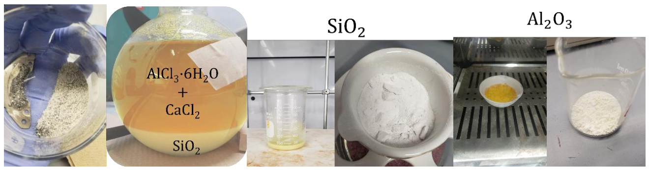
Figure 2.
(a) molten salt electrolysis cell; (b) aluminium metal; (c) drawn into aluminium wire.
Magnox control rods were 316 austenitic stainless steel (67% Fe, 18% Cr, 10% Ni, 2% Mo, 2% Mn and <1% S) rather than high-temperature tolerant Hastelloys because the maximum temperature of 400oC was limited by Magnox alloy tolerance. Fe-based steel with high Cr content such as 316 stainless steel is effective as a gamma-ray shield Fe-based steel with high Cr content such as 316 austenitic stainless steel is effective as a gamma-ray shield. Fe may be sourced from the lunar mineral ilmenite (FeTiO3) and subjected to hydrogen reduction to yield Fe metal within the lunar industrial ecology [1,2]. Ni is sourced from NiFe meteoritic metal through carbonyl process of the lunar industrial ecology [1,2]. NiFe meteoritical metal may be sourced from potential ores on the Moon associated with impact craters [46-48]. For the critical properties of Cr, we require an extension of the lunar industrial ecology to incorporate Cr mining and extraction from lunar chromite (FeCr2O4). Chromite is roasted with Na2CO3 in oxygen converting it into soluble sodium chromate (Na2CrO4) for dissolution in water:
FeCr2O4 + 2Na2CO3 + 3/2O2 → 2Na2CrO4 + FeO + 2CO2
Aqueous sodium dichromate is leached with HCl acid to form sodium dichromate (Na2Cr2O7):
2Na2CrO4 + 2HCl → Na2Cr2O7 + 2NaCl +H2O
Sodium dichromate is precipitated out and reduced by carbothermic reduction to chromia Cr2O3 reconstituting Na2CO3:
2 Na2Cr2O7 + 3C → 2Na2CO3 + 2Cr2O3 + CO2
Cr2O3 may then be reduced through molten salt electrolysis [11]. Mo and Mn which increase hardness may be dispensed with through design accommodation. Control rod material is crucial - B is commonly employed as a control rod material but is rare on the Moon but may be substituted by Co (common in FeNi asteroids and extractible through the carbonyl process of the lunar industrial ecology [1,2] which has similar neutron-absorption properties. Hence, control rod design may be improved by incorporating powdered Co within the 316 austenitic steel tubes which act as “neutron windows”. Given that U extraction requires mining of KREEP minerals, some REE have neutron-absorption properties such as Dy, Y and Yb which may be utilised in mineral form (e.g. xenotime) without extraction being necessary. Ytterbium- and yttrium-containing xenotime may be added as neutron absorbers.
The neutron moderator often requires Zr which can have abundances as high as 1000 ppm on the Moon but this not considered abundant enough. High-pressure light water is the most common moderator (e.g. PWR) and/or coolant which is available on the Moon at 5.6% by mass at the lunar south pole under permanent shadow. AGR adopted a graphite moderator and CO2 gas coolant at 640oC and 4.1 MPa – the same temperature as a coal-fired power station to increase efficiency to 41% from 25% with Magnox. A high temperature corrosion-resistant 20-25 Nb/20 Cr – 25 Ni – 2 Mn stainless steel was adopted for cladding but it had higher neutron absorption than Magnox requiring the use of 3% enriched uranium fuel [30]. Graphite is the common and preferred moderator and the commonly used neutron reflector material, Be, may also be substituted by graphite.
The structure including reactor vessel containment and pipework may be corrosion-resistant 316 stainless steel amongst others rated to 20 bar [30]. This includes mechanically alloyed oxide dispersion strengthening steels with 1% ultrafine oxide powder – both are stable up to 650oC. Mechanically alloyed oxide dispersion strengthening steels retain their strength at high temperature >1000 K and suffer low embrittlement under radiation. To reduce neutron absorption, thinner cladding is enabled with such oxide-dispersing strengthened steel [30]. Silica and/or alumina (from lunar anorthite) forming stainless steels ensure the formation of protective oxide layers. Oxide-dispersing strengthened steel offers reduced neutron embrittlement but steels cannot be used with Pb coolant due to the solubility of alloying Ni in liquid Pb. Gamma ray shielding constructed from Pb, Li and W must be substituted as all are scarce on the Moon. Lunar abundance of Li is low at ~10 ppm [25]. Hydrogen-based material such as water, polyester and water-bearing concrete are effective as neutron shields. Reactor thermal radiators may be constructed from Ti which is readily available from the lunar mineral ilmenite (FeTiO3) through hydrogen reduction followed by molten salt electrolysis [11,2].
Breeder reactors can be constructed from any reactor design by surrounding the reactor with a breeding blanket. Separation of core and blanket with a graphite wall enhances breeding efficiency and simplified fuel processing. The most common breeder reactor is liquid sodium-cooled fast breeder reactors. They are fed natural isotopes because they convert fertile 238U into fissile 239Pu or fertile 232Th into fissile 233U. Fast breeders lack moderators (required for 238U-239Pu breeding) while thermal breeders require moderators to slow neutrons (such as 232Th-233U breeding). They typically use mixed oxide fuel, e.g. 20% PuO2 and 80% UO2. Both fast and thermal neutron breeding are suitable for Th fuel to breed fissile U. This will require significant investigation into the complex fuel handling imposed by employing mixed 232Th/233U rather than natural 238U/235U. Magnox is not a breeder reactor because it breeds less 239Pu than it consumes as 238U. Magnox can be designed to burn thorium with some modifications. Enriched 235U or 239Pu ignition fuel to generate neutrons for initiating the reaction improves the efficiency of conversion of fertile 232Th into fissile 233U through thermal neutron capture. Once sufficient 233U has been produced, its fission process produces neutrons for 232Th to 233U conversion. The challenge for the Magnox modification would be in determining the cladding compatibility, fuel form, multiple fuel management and the neutron balance. The latter is particularly crucial if 233U fission is conducted within the same reactor – there would be no need for fuel recovery, reprocessing and fuel element fabrication.
6. Lunar Reactor Summary
We favour the use of Th as the fuel of choice due to its abundance, its comparatively simple extraction and lack of requirement for enrichment. Its extraction from KREEP resources requires the use of NaOH and HCl which are already incorporated into the lunar industrial ecology [1,2]. In general, most nuclear reactor designs for burning U can be adapted to burning Th. To utilise lunar resources for the construction of nuclear reactors, it is essential to avoid the use of exotic materials. Our lunar-sourced nuclear reactor is comprised thus:
- (i)
- fuel rod cladding of magnesium-aluminium alloy (Magnox) limits the maximum reactor temperature to 400oC so its thermal efficiency is moderate ~25% but still more than double that from Si-based photovoltaics.
- (ii)
- control rods comprising powdered Co (sourced from NiFe asteroidal material) within 316 steel tubes which act as “neutron windows”. These may be mixed with ytterbium and yttrium containing rare earth minerals such as xenotime as neutron absorbers without separation being necessary.
- (iii)
- neutron reflector should be 316L austenitic stainless steel with alloying elements including Cr extracted from lunar minerals.
- (iv)
- neutron moderator is necessary for thermal neutrons to convert 232Th into 233U which may be graphite which must be sourced from carbonaceous chondrite resources.
- (v)
- reactor coolant should be CO2 gas at 400oC which is recycled within the reactor – this requires Brayton/Stirling cycle energy conversion which offer 20/30% thermodynamic efficiencies.
- (vi)
- 316L austenitic stainless steel pressure vessel rated to 20 bar with oxide dispersion.
Rather than reinforced concrete containment structures, lunar nuclear reactor should be buried with vertical surface thermal radiators with integrated coolant pipes to reject waste heat. Regolith is abundant so regolith-based radiation shielding may be implemented similar to such as proposed for human lunar bases [5]. Heat rejection area required for Al radiator with emissivity of 0.9 to reject 6.7 MW heat (30% efficiency with 2 MWe) from 400oC Magnox nuclear reactor to room temperature is given by:
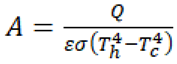 =470 m2 = 22 m x 22 m (3)
This is relatively insensitive to heat sink temperature whether it be rejection to deep space at night or rejection to ambient daytime temperature. The crucial parameter is the emissivity of 0,9 which may be achieved either through anodised alumina coating or alumina/silica multilayer coating. A radiator module comprising a Ti frame and panel with an integrated heat pipe carrying liquid Cs and Ti radiator fins can radiate 56 kWth at 600 K surface temperature to deep space [49]. NaK (78% K) has a slightly lower vapour pressure than Cs so it can be substituted with a higher diameter heat pipe. Ti is available on the Moon recoverable from ilmenite FeTiO3 through hydrogen reduction to yield TiO2 that is reduced to Ti through molten salt electrolysis [11,2]. Na is more abundant than Cr and K is recoverable from KREEP minerals suggesting that NaK manufacture may be feasible. The calculated radiator area is some 20 times smaller in area than an equivalent solar farm. In the next section, we consider space nuclear reactors which require spacecraft radiator mounting but the power levels are much reduced <1 kW which translates to a small radiator area of >0.3 m2 under the same conditions. These are ballpark estimates and do not include practical inefficiencies. Operations in lunar gravity such as fluid pumps that are central to nuclear reactor operation more closely resemble terrestrial behaviours (such as buoyancy-driven convection) than that in microgravity of space (absence of buoyancy-driven convection).
7. Nuclear Rockets
Although nuclear thermal rocket propulsion (NTP) in principle would be capable of launch from lunar and other planetary surfaces, nuclear electric propulsion (NEP) lacks the thrust level for launch. We assume that launch into orbit would be accomplished by electromagnetic launchers – a suitable design that offers lunar escape velocity is the modular Kaye coilgun design [80]. A nuclear thermal rocket engine such as NERVA (nuclear engine for rocket vehicle applications program) requires high performance which imposes severe requirements on material temperature tolerances. It uses fissile enriched uranium pebbles coated with ZrC or in cermet form to heat a hydrogen working fluid flowing through the reactor core to high temperature of 2700 K and expelled through a nozzle to generate 334 kN thrust with Isp ~850-900 s [50]. NERVA is a solid core nuclear reactor limited by the melting point of the reactor pressure vessel. Nuclear lightbulb engine is a closed cycle gas core nuclear engine in which nuclear fuel gas is contained within a quartz-lined reaction chamber to generate Isp~1500-2000 s. Silica can be sourced from lunar resources and grown into quartz. Onboard, cryogenic storage of H2 at 20 K imposes boil-off which decreases with increasing tankage volume - 50 m3 exhibits boil-off of 0.4%/day while 20,000 m3 exhibits boil-off at 0.06% per day. Hydrogen can be stored in complex hydrides, e.g. Mg2FeH6 can store elemental H but the proportion of H mass compared with metal mass is low [51]. Most nuclear rocket failures were due to propellant feed system of pump and valve failures [52]. All NTP programmes have been cancelled – SP-100, Project Tumbleweed, Project Prometheus, DRACO and JETSON.
The bimodal nuclear rocket combines NTP for high thrust with NEP for fuel efficiency [53]. The NTP mode operates the reactor at maximum power using a blanket of cylindrical Be control drums around the core of fuel rods. BC on one side of the drums absorbs neutrons to reduce reactor activity and Be reflects neutrons to increase reactor activity. Rotation of the drums controls neutron flux within the core. Within the core are two independent fluid channels through the core of two different fuel configurations of hot fuel pebbles at 2700 K and cooler solid fuel rods at 1200 K. At high reactor activity in NTP mode, hydrogen fuel is pumped through the open loop hot channels that pass through the ZrC0coated fuel pebbles in the hot core which expands the fuel and it is expelled through a rocket nozzle to generate thrust. At low reactor activity in NEP mode, the hot channels are sealed off by valves. An He/Xe gas mixture circulates through different closed loop double-walled channels through the cooler core of solid fuel rods to drive an electrical generator to ensure electrical power.
The Magnox reactor at 400°C cannot provide sufficient performance for a NTP which requires 2700 K to heat the hydrogen fuel to generate thrust. We favour the NEP approach with Isp~4000-15,000 s which exhibits superior performance specific power (kg/kW) for solar system exploration with more efficient fuel consumption [54].
8. Electric Propulsion for Interplanetary Flight
NEP can dramatically reduce interplanetary transit times such as 2 or 3 months to Mars and minimise radiation exposure and are not reliant on solar energy for outer solar system missions. We review electric propulsion to ascertain the potential for manufacturing ion engines from lunar resources. The pulsed plasma thruster (PPT) is the simplest form of electric propulsion and was deployed on Zond 2. It involves passing an electrical arc between a cathode and anode (spark plug) through a solid fuel to ablate it into a plasma. This plasma is accelerated between an anode and a cathode as an electron current flows through the plasma. The current generates a self-induced electromagnetic field which imposes a Lorentz force on the plasma and expels it at high speed. A capacitor energises the arc which can be pulsed rapidly giving almost continuous operation. The commonest fuel is polytetrafluoroethylene (PTFE) but there are other solid alternatives such as sulphur [55]. Laser-assisted PPT can utilise solid metal propellant such as Al alloy for higher Isp ~3000 s [56]. We do not pursue PPT further due to the combination of fuel constraints and complex laser technology.
Rather than impulsive burns of chemical rockets, electric thrusters accelerate continuously. Ions are generated through electron bombardment of the fuel from a hot cathode. Ionisation energy comprises a significant fraction of power consumed by ion engines. The positive ions must be neutralised by electrons generated from a hot cathode after acceleration. The pulsed thermionic vacuum arc (PTVA) ion thruster is based on thermionic emission between cathode and anode with an Isp of 4825 s without requiring an accelerator grid [57]. A heated tungsten filament emits thermal electrons which are accelerated towards the anode made from the metal propellant such as Al. Focussing of the electron beam is achieved using a Wehnelt cylinder. It is a negatively biased control grid which acts as an electrostatic lens to accelerate the electrons and pinches them to bombard the anode. The positively biased anode boils and evaporates into metal vapour which is ionised due to electron bombardment. Most ion thrusters generate thrust by accelerating a beam of ions electrostatically or electromagnetically with Isp~2000-5000 s but they exhibit low thrusts ~mN imposing significant power burdens ~kW. Electrostatic methods accelerate the ions by Coulomb forces generated by an electric field. Electromagnetic methods accelerate the ions by Lorenz forces generated by an electromagnetic field – this is the magnetoplasmadynamic (MPD) thruster which uses an electromagnet. An electromagnet can be constructed from lunar-sourced silicon steel for a soft magnetic core wound by aluminium wiring. Although applied field MPD require external magnets, self-field configurations do not though at a cost of much higher power input requirements. MPD thrusters are less well developed than other ion engines due to cathode erosion at high ion currents. Superconductor-based readiness enhanced magnetoplasmadynamic electric propulsion (SUPREME) offer an enhanced performance electric propulsion by exploiting high temperature superconductors but they are not as well developed at Hall effect thrusters and gridded ion engines [58]. The commonest propellant in ion engines is the heavy inert gas Xe which is scarce, energy-intensive to extract and purify, and prohibitively expensive. We proceed by constraining the ion engine technology by the potential fuels that can be extracted from lunar in-situ resources.
9. Hall Thrusters
Hall effect thrusters use electrostatic potential generated by an axial electric field between the cylindrical cathode and anode to accelerate ions. A radial magnetic field generated between a central electromagnet and an outer electromagnetic magnetic coil limits the gyroradius of electrons but not that of ions. The combination of electrostatic and magnetic fields causes the electrons to drift (Hall current) and ionise the propellant – this is the Hall thruster. NEP requires nuclear reactor rated to >100 kW to drive a Hall thruster for specific impulses of 22000-4600 s. In a water electrolysis Hall effect thruster (WET-HET), an electrolyser splits water into hydrogen fed to the cathode and oxygen fed to the anode [59]. This enables water to be tanked rather than hydrogen/oxygen gases. It operates similarly to a regenerative fuel cell though it expends the fuel. Biased voltages applied to the electrodes of a microwave and/or electromagnets of a water-fuelled ion engine improves performance [60]. A water vapour fuelled Hall effect thruster has been developed without water electrolysis by using water vapour directly that is 20% less efficient than the oxygen-fuelled thruster [61]. By eliminating hydrogen and the necessity to mine water, oxygen can be recovered from lunar minerals as a byproduct of metal extraction from abundant anorthite [44,45]. An oxygen-fuelled Hall effect thruster has been developed yielding thrust of 27 mN and Isp of 2874 s with a power rating of 2238 W [62]. It had an optimum channel length of 13.1 mm that trades length of the ionisation region against energy losses due to wall-plasma interactions. Although BN/BNSiO2 wall material improves performance by 40% due to lower secondary electron emission over Al2O3 wall material, the latter is available from in-situ resources through HCl leaching of lunar anorthite [44]. Anode material must not form a non-conductive oxidative layer from the oxygen plasma thereby compromising anode function. 316 stainless steel developed a thin oxidised layer that is conductive and permits anode function for long-term operation. Although the thrust is low, these Hall effect thrusters may be arrayed to generate higher thrusts. This places a premium on adopting nuclear reactor power sources.
A 2 kW-class thruster using Mg propellant yielded 23% anode efficiency and thrust-to-weight ratio of 18 mN/kW compared with 40% anode efficiency and thrust-to-weight ratio of 53 mN/kW for a comparable Xe-fuelled Hall thruster [63]. The Mg-fuelled thruster gave a thrust of 34-39 mN, Isp of 2000-2700 s and thrust-to-weight ratio of 24-18 mN/kW at 200-300 V with 1.7 mg/s flow rate. The benchmarked Mg-fuelled thruster gave higher Isp of 2700 s than the similar Xe-fuelled thruster at 1550 s. A Hall effect thruster using a feedable Mg/Zn solid anode fuel that sublimes into a plasma when heated at 450oC has been demonstrated the feasibility of Mg-fuelled Hall thrusters with an Isp of 4000 s [64]. Mg fuel may be extracted from the lunar olivine forsterite (Mg2SiO4) through HCl acid leaching (as in the lunar industrial ecology [1,2]):
Mg2SiO4 + 4HCl + 4H2O → 2MgCl2 + H4SiO4
MgCl2 + Ca(OH)2 → Mg(OH)2 + CaCl2
Mg(OH)2 is calcined at 400oC to yield MgO which is then reduced to Mg metal by molten salt electrolysis using the CaCl2 waste as electrolyte [9].
10. Gridded Ion Thrusters
Gridded ion thrusters implement separate ionisation and ion acceleration. Ionisation is achieved using a hot cathode-based electron gun that accelerates electrons across a potential difference to an anode. In a Kaufman thruster, an electric field is generated by a potential field between a hollow cathode and the anode to bombard the fuel with electrons. In a radio frequency ion thruster, electrons are accelerated by an oscillating electric field generated by alternating electromagnets to bombard the fuel – this is cathodeless as it is self-sustaining. A variation on this is to use microwave heating by a magnetron to accelerate electrons. In all cases, the ions are accelerated through two or three grids by a potential difference between the grids (screen and accelerator grids). A second cathode emits electrons to neutralise the ion beam to prevent it from being attracted to the spacecraft. The most significant limit in gridded ion thrusters is grid erosion due to fuel ion sputtering. Ion thruster grids are typically constructed from molybdenum or carbon-carbon. A metal propellant was used in a metal ion thruster-magnetron electron bombardment (MIT-MEB) which was bombarded by an electron beam to generate metal ions [65]. A hot ~1300oC tungsten filament cathode generated thermionic electrons within a ceramic chamber (options include alumina or magnesium aluminate spinel derived from lunar resources [66]. An electric potential of 1-5 kV accelerated the thermal electrons to higher energies to ionise the metal gas. An Nd permanent magnet ~0.15-0.25 T guided the electrons to the metal target (substitutable with AlNiCo magnets derived from lunar resources). The metal ions were accelerated through an accelerator grid to generate thrust. A neutraliser downstream of the accelerator grid neutralised the ions. Zn propellant was used to demonstrate thrusts of 10 μN using 26 W but Mg would also be suitable [65].
A miniature microwave discharge ion thruster that uses electron cyclotron resonance to heat water vapour as a propellant has been demonstrated [67,68]. 0.15 T SmCo magnets around an antenna within the titanium discharge chamber generated the plasma for electrical acceleration through the screen grid (1.4 kV) and the accelerator grid (-200 V). The neutraliser was similarly constructed as the ion source. Electron cyclotron resonance with water as propellant yields reduced propellant efficiency and specific impulse in comparison with xenon [69]. Microwave-generated electron cyclotron resonance eliminates the need for an electrode in the discharge chamber. Multi-grid ion thrusters based on water may be arrayed with nuclear power sources to explore the solar system. Dual-stage 100 kW nuclear powered four-gridded ion thrusters operating at 30 kV with Isp of 12,000 s and thrusts ~1 N for a mass-to-power ratio of 25 kg/kW could yield interstellar precursor capabilities to 200 AU within 25 years travel times [70,71]. However, these performances were obtained using Xe propellant with low ion beam divergence ~2o. Nevertheless, four gridded ion engines yield superior performance than dual- or tri-gridded engines.
We propose that the lunar-resourced ion engine may be constructed from lunar resources:
- (i)
- Outer housing of aluminium derived from lunar anorthite.
- (ii)
- Electron gun (cathode) of tungsten rather than molybdenum – it is siderophilic so it is most likely sourced in iron-nickel derived from M-type asteroid impactors – with alumina/quicklime coating.
- (iii)
- Reaction chamber of 316 stainless steel or titanium alloy (Ti6Al with V substituted by Ni and/or Cr for the β form) with ceramic liner (alumina-silica composite rather than boron nitride-silica composite or carbon-carbon composite).
- (iv)
- Aluminium wire-wound magnetic iron core and/or permalloy for magnetic field shaping.
- (v)
- Anode of 316 stainless steel with graphite coating.
- (vi)
- Grids of tungsten rather than molybdenum or carbon-carbon composite.
- (vii)
- Electrical insulation of alumina.
- (viii)
- Thermal insulation of silica or spinel.
11. Electron Gun Interface
In most NEP concepts, thermal energy generated by the nuclear reactor is converted into electrical energy through a solid-state thermoelectric converter. This electrical energy is managed through a power conditioning and distribution system to the various electrical loads including batteries/capacitors. This includes the electric propulsion system which uses electrical energy to power the electron gun and electrostatic/electromagnetic acceleration of the ions of the ion engine. The candidate nuclear reactor could power ion engines in this fashion. The electrical power feed through two channels in the ion engine – the electron gun and the ion accelerator. In the electron gun channel, there are energy losses due to energy conversions that can be circumvented: nuclear thermal energy → electrical energy → thermal energy to heat the cathode of the electron gun → electron energy output of the electron gun. This is wasteful so a direct drive channel should be implemented: Nuclear thermal energy → heat cathode of the electron gun → electron energy output of the electron gun. This converts nuclear thermal energy directly into ionisation of the electric propellant. Such electron guns can be arrayed to increase power input to the ion engine. This requires specific conditions for the interface to the electron gun.
The hot filament/hollow cathode of the electron gun is fundamental to all ion engines for both ionisation of propellant and downstream neutralisers of those ions following acceleration. Thermionic current density J is determined by the Richardson-Dushman equation:
(4)
where A=Richardson constant=120 A/cm2/K, φ=thermionic work function, T=absolute temperature. V=applied voltage. For an ion thruster, J must be ~0.1-1 A/cm2. Thermionic current is critically dependent on temperature (high temperature ~1000oC favouring refractory metals such as tungsten) and a low work function (eV) (requiring coatings). Thruster cathodes are typically tungsten filament (φ=4.5 eV) coated in LaB6 (φ=2.3 eV), ThO2 (φ=2.6 eV) or Cs2O (φ=1.2 eV) to reduce the composite work function of the cathode to below that of metal and coating individually due to partial electron transfer from the coating to the substrate. Composite BaO (φ=1.1 eV)/CaO (φ=1.6 eV)/Al2O3 (4.7 eV) coatings also reduce the work function of tungsten for electron emission lowering the heating temperature for electron emission. The latter two oxides are available from lunar resources which can partially reduce the work function but the latter two coatings facilitate the BaO coating which is critical but thoriated tungsten requires locally-available thorium. The lowest work function material is BaMoO3 with φ=1.25 eV which promises >30% thermionic conversion efficiency at 1500oC [72] but this is not a viable lunar resource. A p-doped Si substrate onto which K was deposited in oxygen at 1000 K forming a K2O layer yielded a very low work function of 1.35 eV [73]. This was due to the formation of surface dipoles due to charge transfer between K and O. K is extractible from lunar orthoclase feldspar (KAlSi3O8) using HCl acid leaching to yield KCl – molten KCl may be electrolysed in CaCl2 electrolyte to K metal and oxidised to K2O. Even at 1.35 eV, the thermionic emission temperature must be >1000 K rendering Magnox which operates at 400oC unsuitable for ion engine applications through direct thermal heating of the ion engine cathode. Cold field emission cathodes as electron sources are not suited to lunar resourcing as they require exotic materials such as Mo (φ=3.35 eV) or Si (φ=3.35 eV) with nanostructuring coated with diamond/carbon films for micro-electric propulsion [74,75]. Cold field emission of electrons requires applied electric fields ~50-100 V rather than thermal energy to allow electron tunnelling from the material through Fowler-Nordheim emission. To reduce the electric field intensities, Spindt cathodes exploit sharp tips to enhance electric field geometry giving work functions ~4-5 eV. Negative electron affinity (NEA) film emission sources – such as carbon film, diamond film, BN film - mounted onto a metal substrate forms a Schottky barrier which can be reduced by doping the film with electron donors. Cold emission cathodes require microfabrication methods which are demanding for lunar manufacturing facilities. Microfabrication requires ultrapurification processes (such as zone refining), suites of reagents (including ion echants), complex processes (such as lithography and vapour deposition) and suites of microscopic measurement devices. Given this, the Magnox reactor lacks the performance required for direct NEP which requires very high temperature nuclear reactors >1000oC.
Such a very high temperature nuclear reactor requires exotic materials such as refractory cladding, Be reflectors, B4C control rods, NaK/molten salt/He coolant, etc. The most promising is the He gas-cooled very high temperature reactor. Supercritical CO2 is a fluid beyond its critical point that can be used as coolant up to 700oC yielding efficiencies ~50%. Supercritical CO2’s corrosivity generates carburisation of steels requiring 316 austenitic stainless steels and nickel-based superalloys such as alloy 617 (including Co, Mo, W, Cr, Al) by forming a Cr2O3 protective layer [76]. A small modular supercritical CO2 gas fast reactor burning 12%-enriched 235UO2 fuel at 650oC/20 MPa (near the critical point) offers 200 MWth with 50% thermal efficiency through the Brayton cycle [77]. The cladding was 316 stainless steel for corrosion-resistance up to 650oC. Their disadvantage is that supercritical CO2 has poor neutron moderator performance requiring ZrH rods [78] and so requires sourcing and extraction of Zr. At temperatures >500oC, CO2 is corrosive. Helium gas coolant can operate at 1000oC. In He, at 850-950oC, 87% of carbides deposited in alloy 617 are chromium carbides but at 950-1000oC, decarburisation occurs due to carbides reacting with oxygen [76]. The very high temperature gas cooled reactors could employ cermet Ni-Co-Ti-Fe-based superalloys with oxide dispersion (TiO2 and Al2O3) to replace Mo and Cr for high temperature corrosion resistance. An alternative would be to supplement the nuclear reactor with solar concentrators to enhance the temperature, and so efficiency, of thermionic conversion [4] but this would be restricted to within the inner solar system and become increasingly ineffective beyond Mars.
Nevertheless, the Magnox reactor can still power electric propulsion for NEP but indirectly through dynamic conversion such as the Brayton cycle, albeit at a lower thermal efficiency ~25-30%. This has implications for the aluminium thermal radiators to dissipate waste heat. For the QinetiQ T6 ion engine with a power requirement of 2.5 kW for a thrust of 150 mN, the Magnox reactor must generate 8.3 kW and the radiator area A=0.55 m2 per engine radiating to deep space. This is considerably smaller than the solar panel area of ~6 m2 required for solar-electric propulsion with the same energy output (assuming 30% efficiency) estimated without end-of-life losses or battery charging requirements which render the solar array option even more unattractive. NEP offers the means to explore the solar system from Mars to Jupiter to Saturn with enhanced performance over chemical propulsion [79].
12. Conclusion
It appears feasible to manufacture a NEP system from lunar resources given certain requirements and constraints. This requires extensive use of graphite and CO2 coolant which requires a carbon source – the Moon’s repository of carbon is ~100 ppm suggesting that asteroid mining of carbon will be necessary. The industrial infrastructure required to support in-situ nuclear power plant construction will likely be at least a second-generation lunar industrial infrastructure. The Magnox reactor will not be particularly high performing nor efficient due to its low operating temperature. However, given that it is not launched from Earth and that it is emplaced on the expansive lunar surface, its mass and volume are not constrained. Although we have considered the resource availability aspect of constructing NEP systems on the Moon, we have not addressed the downstream aspects of manufacturing which introduces its own set of challenges. Nevertheless, we have indicated that the resource availability aspect does not disallow NEP production on the Moon. The Moon is a staging post to the rest of the solar system but our solar system exploration infrastructure must be sustainable. It has long been proposed that mass drivers can provide launch capabilities from the Moon’s surface to lunar orbit, perhaps to the Gateway. This trades renewable electrical power supply for a Δv of 3.7 km/s against consumption of locally-mined but scarce LH2/LOX from the lunar poles. For in-space propulsion, we can replace LOX/LH2 or CH4/O2 chemical propulsion with NEP. For example, the Δv to get to Mars is 3.0 km/s requiring 568 tonnes LH2/LOX for the Mars Design Reference Architecture 5.0. If NEP is employed using an ion engine burning O2 sourced from lunar minerals, we require only 110 tonnes O2 ceteris paribus, i.e. less than 20% of the fuel required for chemical propulsion without burning any hydrogen. Finally, the deployment of lunar-manufactured NEP opens low-cost expansion through the solar system and beyond.
Funding Sources: This work was not funded.
References
- Ellery, A. Sustainable in-situ resource utilisation on the Moon. Planet. Space Sci. 2020, 184(4), 104870. [Google Scholar] [CrossRef]
- Ellery, A. Lunar industrial ecology as the core of a sustainable industrial capacity on the Moon. Chem. Eng. Res. Des. 2026, 212, 875–893. [Google Scholar] [CrossRef]
- Ellery, A. Are there biomimetic lessons from genetic regulatory networks for developing a lunar industrial ecology? Biomim. J. 2021a, 6(3), 50. [Google Scholar] [CrossRef] [PubMed]
- Ellery, A. Generating and storing power on the Moon using in-situ resources. Proc. IMechE J. Aerosp. Eng. 2021b, 236(6), 1045–1063. [Google Scholar] [CrossRef]
- Ellery, A. Leveraging in-situ resources for lunar base construction. Can. J. Civ. Eng. 2021c, 49(5), 657–674. [Google Scholar] [CrossRef]
- Ellery, A. Self-replication technology for ubiquitous space exploration. 75th Int Astronautical Congress (IAC), Milan, 2024; p. IAC-24-D4.1.9x80842. [Google Scholar]
- Ellery, A. Are 3D printers universal constructors? Proc ASCE Earth & Space Conf, Florida International University, Miami, FL, 2024; p. 3666. [Google Scholar]
- Papike, J.; Taylor, L.; Simon, S. “Lunar minerals” in Lunar Sourcebook; Heiken, G., Vaniman, D., French, B., Eds.; Cambridge University Press: UK, 1991; pp. 121–181. [Google Scholar]
- Maurette, M. Fossil nuclear reactors. Annu. Rev. Nucl. Sci. 1976, 26, 319–350. [Google Scholar] [CrossRef]
- Hou, Z.; Gong, Q.; Liu, N.; Jiang, B.; Li, J.; Wu, Y.; Huang, J.; Gu, W. Elemental abundances of Moon samples based on statistical distributions of analytical data. Appl. Sci. 2023, 13(1), 360. [Google Scholar] [CrossRef]
- Ellery, A.; Mellor, I.; Wanjara, P.; Conti, M. Metalysis FFC process as a strategic lunar in-situ resource utilisation technology. New Space J. 2022, 10(2), 224–238. [Google Scholar]
- Ellery, A.; Elaskri, A. 3D printing modules for self-assembling space systems. Prog. Aerosp. Sci. 2025, 157, 101128. [Google Scholar] [CrossRef]
- Yamashita, N.; Hasebe, N.; Reedy, R.; Kobayashi, S.; Karouji, Y.; Hareyama, M.; Shibamura, E.; Kobayashi, M.-N.; Okudaira, O.; d’Uston, C.; Grasnault, O.; Forni, O.; Kim, K. Uranium on the Moon: global distribution and U/Th ratio. Geophys. Res. Lett. 2010, 37, L10201. [Google Scholar] [CrossRef]
- Zhu, M.-H.; Chang, J.; Ma, T. Thorium distribution on the Moon: new insights from Chang’E-2 gamma ray spectrometer. Res. Astron. Astrophys. 2019, 19(6), 76. [Google Scholar] [CrossRef]
- Zhang, J.; Liu, J. Thorium anomaly on the lunar surface and its indicative meaning. Acta Geochim. 2024, 43, 507–519. [Google Scholar] [CrossRef]
- Zhang, J.; Liu, J. Thorium anomaly on the lunar surface and its indicative meaning. Acta Geochim. 2024, 43, 507–519. [Google Scholar] [CrossRef]
- Dallas, J.; Raval, S.; Saydam, S.; Dempster, A. Investigating extraterrestrial bodies as a source of critical minerals for renewable energy technology. Acta Astronaut. 2021, 186, 74–86. [Google Scholar] [CrossRef]
- McLeod, C.; Krekeler, M. Sources of extraterrestrial rare earth elements: to the Moon and beyond. Resources 2017, 6, 40. [Google Scholar] [CrossRef]
- Zou, Y.-L.; Liu, J.-Z.; Liu, J.-J.; Xu, T. Reflectance spectral characteristics of lunar surface materials. Chin. J. Astron. Astrophys. 2004, 4(1), 97–104. [Google Scholar] [CrossRef]
- Kim, K. South Pole-Aitken basin region, Moon: GIS-based geologic investigation using Kaguya elemental information. Adv. Space Res. 2012, 50, 1629–1637. [Google Scholar] [CrossRef]
- Carlson, R. Robotic sample return reveals lunar secrets. Nature 2021, 600 (Dec), 39–40. [Google Scholar] [CrossRef]
- Kim, R.; Cho, H.; Han, K.; Kim, K.; Mun, M. Optimisation of acid leaching of rare-earth elements from Mongolian apatite-based ore. Minerals 2016, 6(3), 63. [Google Scholar] [CrossRef]
- Xie, F.; Zhang, T.; Dreisinger, D.; Doyle, F. Critical review on solvent extraction of rare earths from aqueous solution. Miner. Eng. 2014, 56 (Feb), 10–28. [Google Scholar] [CrossRef]
- Haertling, C.; Hanrahan, R. Literature review of thermal and radiation performance parameters for high-temperature uranium dioxide fueled cermet materials. J. Nucl. Mater. 2007, 366, 317–335. [Google Scholar] [CrossRef]
- Dreibus, G.; Spettel, B.; Wanke, H. Lithium and halogens in lunar samples. Phil Trans. R. Soc. A 1977, 285, 49–54. [Google Scholar] [CrossRef]
- Taylor, S.; Hodges, R. Chlorine and sulphur abundances in Mars and the Moon: implications for bulk composition. Lunar Planet. Sci. Abstr. XII 1981, 1082–1084. [Google Scholar]
- Halim, S.; Crawford, A.; Collins, G.; Joy, K.; Davison, T. Assessing the survival of carbonaceous chondrites impacting the lunar surface as a potential resource. Planet. Space Sci. 2024, 246, 105905. [Google Scholar] [CrossRef]
- Yang, Y.; Li, S.; Zhu, M.-H.; Liu, Y.; Wu, B.; Du, J.; Fa, W.; Xu, R.; He, Z.; Wang, C.; Xue, B.; Yang, J.; Zou, Y. Impact remnants rich in carbonaceous chondrites detected on the Moon by the Chang’e 4 rover. Nat. Astron. 2022, 6, 207–213. [Google Scholar] [CrossRef]
- Schubert, P.; Marrs, I.; Daniel, E.; Conaway, A.; Bhaskaran, A. Ultra-safe nuclear thermal rockets using lunar-derived fuel. J. Space Saf. Eng. 2021, 8, 185–192. [Google Scholar] [CrossRef]
- Ortner, S. Review of structural material requirements and choices for nuclear power plant. Front. Nucl. Eng. 2023, 2, 1253974. [Google Scholar] [CrossRef]
- Nikitaeva, D.; Thomas, D. Analysis of small modular nuclear reactor construction on the Moon. J. Br. Interplanet. Soc. 2023, 76, 56–69. [Google Scholar] [CrossRef]
- Narendranath, S.; Pillai, N.; Tadepalli, S.; Sarantos, M.; Vadodariya, K.; Sarwade, A.; Radhakrishna, V.; Tyagi, A. Sodium distribution on the Moon. Astrophys. J. Lett. 2022, 937(2), L23. [Google Scholar] [CrossRef]
- Nascimento, J.; Guimaraes, L.; Ono, S. Fuel, structural material and coolant for an advanced fast micro-reactor. J. Br. Interplanet. Soc. 2014, 67, 381–389. [Google Scholar]
- El-Genk, M. Space nuclear reactor power concepts with static and dynamic energy conversion. Energy Convers. Manag. 2008, 49, 402–411. [Google Scholar] [CrossRef]
- McClure, P.; Poston, D.; Gibson, M.; Mason, L.; Robinson, C. Kilopower project: the KRUSTY fission power experiment and potential missions. Nucl. Technol. 2020, 206, S1–S12. [Google Scholar] [CrossRef]
- Satyala, N.; Krasinski, J.; Vashaee, D. Thermoelectric properties of Mg2Si doped with Bi and Al with conductive glass inclusion. IEEE Green Technologies Conf, Tulsa, OK, 36; 2012. [Google Scholar]
- Schwede, J.; Sarmiento, T.; Narasimhan, V.; Rosenthal, S.; Riley, D.; Schmitt, F.; Baragatin, I.; Saharabuddhe, K.; Howe, R.; Melosh, N.; Shen, Z.-X. Photon-enhanced thermionic emission from heterostructures with low interface recombination. Nat. Commun. 2013, 4, 1576. [Google Scholar] [CrossRef] [PubMed]
- Brey, H. Evolution and future development of the high temperature gas cooled reactor. Int. Conf. Glob. Environ. Energy Syst. Nucl. Power Plants 2003, 1194. [Google Scholar]
- Crawford, I.; Anand, M.; Barber, S.; Cowley, A.; Crites, S.; Fa, W.; Flahaut, J.; Gaddis, L.; Greenhagen, B.; Haruyama, J.; Hurley, D.; McLeod, C.; Morse, A.; Neal, C.; Sargeant, H.; Sefton-Nash, E.; Tartese, R. Lunar resources. Rev. Mineral. Geochem. 2023, 89, 829–868. [Google Scholar] [CrossRef]
- Beck, J.; Pincock, L. Idaho National Laboratory report INL/EXT-10-19329; High temperature gas-cooled reactors lessons learned applicable to the next generation nuclear plant. 2011.
- Victoria, M.; Baluc, N.; Spatig, P. Structural materials for fusion reactors. 2020. Available online: https://www-pub.iaea.org/mtcd/publications/pdf/csp_008c/pdf/ftp1_13.pdf.
- Gallo, B.; El-Genk, M. Brayton rotating units for space reactor power systems. Energy Convers. Manag. 2009, 50(9), 2210–2232. [Google Scholar] [CrossRef]
- Zubrin, R.; Muscatello, A.; Berggren, D. Integrated Mars in situ propellant production system. ASCE J. Aerosp. Eng. 2012, 26(1), 43–56. [Google Scholar] [CrossRef]
- Thibodeau, B.; Walls, X.; Ellery, A.; Cousens, B.; Marczenko, K. Extraction of silica and alumina from lunar highland simulant. Proc ASCE Earth & Space Conf, 2024; p. paper 6962. [Google Scholar]
- Walls, X.; Ellery, A.; Marczenko, K.; Wanjara, P. Aluminium metal extraction from lunar highland simulant using electrochemistry. Proc ASCE Earth & Space Conf, 2024; p. paper 7061. [Google Scholar]
- Liu, X.; Gu, L.; Tian, H.-C.; Li, J.; Tang, X.; Hi, S.; Lin, Y. First classification of iron meteorite fragment preserved in Chang’e 5 lunar soils. Sci. Bull. 2024, 69, 554–561. [Google Scholar] [CrossRef] [PubMed]
- Yue, Z.; Johnson, B.; Minton, D.; Melosh, H.; Di, K.; Hu, W.; Liu, Y. Projectile remnants in central peaks of lunar impact craters. Nat. Geosci. 2013, 6 (Jun), 435–437. [Google Scholar] [CrossRef]
- James, P.; Smith, D.; Byrne, P.; Kendall, J.; Melosh, J.; Zuber, M. Deep structure of the lunar south pole Aitken Basin. Geophys. Res. Lett. 2019, 46, 5100–5106. [Google Scholar] [CrossRef]
- Schriener, T.; El-Genk, M. Launch solid stress analyses of ultra-lightweight heat rejection radiator module and panel for lunar fission surface power. J. Br. Interplanet. Soc. 2025, 78, 92–103. [Google Scholar] [CrossRef]
- Bruno, C.; Dujarric, C. In-space nuclear propulsion. Acta Astronaut. 2013, 82, 159–165. [Google Scholar] [CrossRef]
- Nasuti, F.; Betti, B.; Balucani, M. Hydrogen storage material for microthrusters: basic performance analysis. Acta Astronaut. 2012, 80, 52–57. [Google Scholar] [CrossRef]
- Rawlins, S.; Thomas, D. Reliability assessment of nuclear thermal engine configuration and health monitoring. J. Br. Interplanet. Soc. 2023, 76, 145–152. [Google Scholar] [CrossRef]
- Polzin, K.; Schleicher, R. Reimagined nuclear rocket. IEEE Spectr. (Sep) 2026, 36–43. [Google Scholar] [CrossRef]
- Niehoff, J.; Friedlander, A. Comparison of advanced propulsion capabilities for future planetary missions. J. Spacecr. Rocket. 1974, 11(8), 566–773. [Google Scholar] [CrossRef]
- Ling, W.; Zhang, S.; Fu, H.; Huang, M.; Quansah, J.; Liu, X.; Wang, N. Brief review of alternative propellants and requirements for pulsed plasma thrusters in micropropulsion applications. Chin. J. Aeronaut. 2020, 33(12), 2999–3010. [Google Scholar] [CrossRef]
- Zhao, Y.; Tan, S.; Wu, J.; Zhang, Y.; Ou, Y.; Zheng, P. Ablation characteristics of laser-assisted pulsed plasma thruster with metal propellant. Plasma Sci. Technol. 2021, 23, 104007. [Google Scholar] [CrossRef]
- Velicu, I.-L.; Tiron, V.; Petrea, M.-A.; Popa, G. New concept of metal ion thruster based on pulsed thermionic vacuum arc discharge. Plasma Sources Sci. Technol. 2021, 30, 015006. [Google Scholar] [CrossRef]
- Betancourt, M.; Bogel, E.; Collier-Wright, M.; Wilcox, J.; Kaplan, P. Comparative overview of nuclear electric propulsion programs and concepts. J. Br. Interplanet. Soc. 2022, 75, 226–230. [Google Scholar]
- Scwertheim, A.; Knoll, A. Water electrolysis Hall effect thruster (WET-HET): paving the way to dual mode chemical electric water propulsion. Proc Int Electric Propulsion Conf, Vienna, 2019; p. IEPC-2019-A-259. [Google Scholar]
- Ataka, Y.; Nakagawa, Y.; Koizumi, H.; Komurasaki, K. Improving the performance of a water ion thruster using biased electrodes. Acta Astronaut. 2021, 187, 133–140. [Google Scholar] [CrossRef]
- Tejeda, J.; Knoll, A. Water vapour fuelled Hall effect thruster: characterisation and comparison with oxygen. Acta Astronaut. 2023a, 211, 702–715. [Google Scholar] [CrossRef]
- Tejeda, J.; Knoll, A. Oxygen-fuelled Hall effect thruster: channel length, ceramic walls and anode material experimental analyses. Acta Astronaut. 2023b, 203, 268–279. [Google Scholar] [CrossRef]
- Hopkins, M.; King, L. Performance comparison between a magnesium and xenon-fuelled 2 kW Hall thruster. AIAA J. Propuls. Power 2016, 32(4), 1015–1021. [Google Scholar] [CrossRef]
- Makela, J.; Washeleski, R.; Massey, D.; King, L.; Hopkins, M. Development of a magnesium and zinc Hall effect thruster. Proc Int Electric Propulsion Conf, Michigan, 2009; p. IEPC-2009-107. [Google Scholar]
- Chen, K.-Y.; Chang, P.-Y.; Lin, W.-Y. Metal ion thruster using magnetron electron beam bombardment (MIT-MEB). Plasma Sources Sci. Technol. 2020, 29, 06502. [Google Scholar] [CrossRef]
- Ellery, A. Ceramics – the forgotten but essential ingredients for a circular economy on the Moon. Ceramics 2025, 8(3), 107. [Google Scholar] [CrossRef]
- Nakagawa, Y.; Koizumi, H.; Kawahara, H.; Komurasaki, K. Performance characterisation of a miniature microwave discharge ion thruster operated with water. Acta Astronaut. 2019, 157, 294–299. [Google Scholar] [CrossRef]
- Motoki, T.; Takasaki, D.; Koizumi, H.; Ataka, Y.; Komurasaki, K.; Takao, Y. Experimental study on the performance characteristics of a miniature microwave discharge cathode. Acta Astronaut. 2022, 196, 231–237. [Google Scholar] [CrossRef]
- Nakagawa, Y.; Koizumi, H.; Naito, Y.; Komurasaki, K. Water and xenon ECR ion thruster – comparison in global model and experiment. Plasma Sources Sci. Technol. 2020, 29, 105003. [Google Scholar] [CrossRef]
- Fearn, D.; Walker, R. Interstellar precursor missions using advanced dual-stage ion propulsion systems. 2006. Available online: https://www.esa.int/gsp/ACT/doc/ACTAFUTURA/AF02/papers/AF02.2006.45.pdf.
- Bramati, C.; Izzo, D.; Samaraee, T.; Walker, R.; Fearn, D. Very high delta-v missions to the edge of the solar system and beyomd enabled by the dual-stage 4-grid ion thruster concept. Acta Astronaut. 2009, 64, 735–744. [Google Scholar] [CrossRef]
- Schindler, P.; Antoniuk, E.; Cheon, G.; Zhu, Y.; Reed, E. Discovery of stable surfaces with extreme work functions by high throughput density functional theory and machine learning. Adv. Funct. Mater. 2024, 34, 2401764. [Google Scholar] [CrossRef]
- Morini, F.; Dubois, E.; Robillard, J.; Monfray, S.; Skotnicki, T. Low work function thin film growth for high efficiency thermionic energy converter: coupled Kelvin probe and photoemission study of potassium oxide. Physica Status Solidi 2014, 211(6), 1334–1337. [Google Scholar] [CrossRef]
- Marrese, C. Review of field emission cathode technologies for electric propulsion systems and instruments. IEEE Aerospace Conf, Big Sky, 2000; pp. 85–97. [Google Scholar]
- Fomani, A.; Akinwande, A.; Velasquez-Garcia, L. Resilient, nanostructures, high current and low voltage neutralisers for electric propulsion of small spacecraft in low Earth orbit. J. Phys. Conf. Ser. 2013, 476, 012014. [Google Scholar] [CrossRef]
- Lee, J.; Pint, B. “Corrosion in gas-cooled reactors” Oak Ridge National Laboratory Report. 2021; p. TLR-RES/DE/CIB-CMB-2021-04. [Google Scholar]
- Parma, E.; Wright, S.; Vernon, M.; Fleming, D.; Rochau, G.; Ahti, S.-A.; Rashdan, A.; Tsvetkov, P. Supercritical CO2 direct cycle gas fast reactor (SC-GFR) concept. In Sandia National Laboratories report; 2011; pp. SAND2011–2525. [Google Scholar]
- Wang, L.; Lu, D.; Yao, L.; Xiang, H.; Zhao, C. Study on temperature feedback effect on supercritical CO2-cooled reactor. Front. Energy Res. 2021, 9, 764906. [Google Scholar] [CrossRef]
- Miao, X.; Zhang, H.; Wang, Q.; Xia, Y.; Sun, W. Optimum design of nuclear electric propulsion spacecraft for deep space exploration. Energy Rep. 2022, 8, 9629–9641. [Google Scholar] [CrossRef]
- Kaye, R. Operational requirements and issues for coilgun electromagnetic launchers. IEEE Trans. Magn. 2005, 41(1), 194–199. [Google Scholar] [CrossRef]

Table 1.
Single metal oxide abundances.
| Elemental Oxide | Lunar Abundance |
| SiO2 | 44.89 |
| Al2O3 | 17.49 |
| FeO | 12.15 |
| TiO2 | 2.52 |
| CaO | 12.11 |
| MgO | 8.83 |
| Na2O | 0.443 |
| Cr2O3 | 0.269 |
Disclaimer/Publisher’s Note: The statements, opinions and data contained in all publications are solely those of the individual author(s) and contributor(s) and not of MDPI and/or the editor(s). MDPI and/or the editor(s) disclaim responsibility for any injury to people or property resulting from any ideas, methods, instructions or products referred to in the content. |
© 2026 by the authors. Licensee MDPI, Basel, Switzerland. This article is an open access article distributed under the terms and conditions of the Creative Commons Attribution (CC BY) license (http://creativecommons.org/licenses/by/4.0/).
Copyright: This open access article is published under a Creative Commons CC BY 4.0 license, which permit the free download, distribution, and reuse, provided that the author and preprint are cited in any reuse.