
Submitted:
02 November 2026
Posted:
04 November 2026
You are already at the latest version
Abstract
This paper demonstrates that a power grid may be fully protected from E3 high-altitude magnetic pulses (HEMP) using E3 arrestor devices placed at substations that represent any vertex cover of the grid. This serves as a simple linear time check to see if pre-existing E3 arrestor-type assets are sufficient for the mitigation of E3 HEMP waveforms. The algorithm to determine where to place new arrestor devices is computationally inexpensive, with a runtime of 8 ms for an 18-bus test case and a runtime of 486 ms for a 150-bus test case in MATLAB to determine the bounding case approximation. The algorithm accomplishes this by finding the minimum vertex cover of the grid and placing E3 arrestor devices in those locations. Since computing the minimum vertex cover is NP-Hard, the algorithm approximates this by computing the solution of a linear program combined with a heuristic based on the four color theorem and knowledge of the permissible substations to upgrade (i.e. substations with E3 arrestors). If the solution exists, it guarantees the near zeroing out of flux across all transformers. If some flux can be tolerated, there may exist an even smaller set of substations to protect that allow system specifications to be met. Additionally, if there already exist devices that make up a vertex cover on the grid, then it is guaranteed that the grid is already protected from E3 disturbances. The check for this distribution of devices is linear in time. The vertex cover solution may be used with other optimization techniques as a homotopy to find the minimum number of required E3 arrestors. The minimum vertex cover is the bounding case solution for the E3 arrestor device.
Keywords:
HEMP mitigation
; power grid resilience
; control theory
; LQR
; graph theory
1. Introduction
In the recent years, there has been a growing interest in the mitigation of disturbances due to high-altitude electromagnetic pulses (HEMP) on the power grid [1,2]. The HEMP threat is traditionally split into three components: the , , and . Each component poses their own unique threat to the grid. The and portions are high power, short-time span insults, whereas the portion is a lower frequency, lower power, longer time span threat. All portions of the HEMP disturbance are capable of saturating transformer cores by inducing current through transmission lines and out through ground on the neutral paths of the transformers. A similar phenomenon was seen in the 1989 Hydro-Quebec incident wherein a coronal mass ejection led to geomagnetically induced currents. Transformers were saturated and the grid eventually collapsed [3]. Core saturation can also lead to overheating of transformers and the breakdown of components within transformers. This paper demonstrates how a power grid may be fully protected from an HEMP disturbance using arrestor devices placed at substations that make up any vertex cover of the grid.
Mitigation devices can be categorized under four main archetypes, seen in Figure 1.
The high-side controller sits on the transmission line side of a transformer and pushes geomagnetically induced currents away from the associated substations. The neutral blocking controller is placed on the neutral path to ground of a transformer. It works by rejecting current through the transformer core, preventing magnetic core saturation of the individual transformer. The load-side controller works by drawing power from the HEMP disturbance away from the neutral path to ground and into a storage device on the load-side of the transformer. The final controller archetype is the one being studied in the paper. This is the arrestor and it is a current source that is attached to the bus of a substation. It works by redirecting current from the HEMP insult through safe paths to ground and away from transformer neutral paths to ground. The device is akin to a lightning arrestor, but instead of remaining high impedance at relatively low (60 Hz) frequencies and low at high frequencies, the device is low impedance at low frequency (<1 Hz) and high at 60 Hz. The remainder of this introduction will serve as a literature review on the currently proposed solutions. As it stands, there are no widespread deployed mitigation solutions for the HEMP disturbance problem on North American grids.
Literature on the topic often advocates for blocking capacitors (passive, integral controllers) on transformer paths to ground. In fact, it is typically stated that these neutral blocking capacitors are the optimal device for HEMP mitigation [4,5,6,7,8,9]. The neutral blocking capacitors are a suitable option for geomagnetic disturbance (GMD) mitigation due to the low-frequency nature of the waveform. For a pseudo-DC signal, the blocking capacitor makes an effective open circuit for the disturbance, but allows the [round-precision=0]60 power signals to pass through with minimal impedance. However, it has been shown in [10,11] that the portion of the HEMP waveform contains sufficiently high-frequency components such that the capacitor does not appear to be an open circuit to the disturbance. Additionally, the blocking capacitor adds an integration term to the system. By including this integral term in series with the inductance of the transformer core, the dynamics of the system increase from first order to second order; as such, impulses to the system will generate ringing. This is seen in [10,11], where the portion of the HEMP waveform has sufficiently high frequency to trigger ringing in the system. This phenomenon is called ferroresonance and has been documented in the literature [12,13].
An additional issue with this solution has to do with the phenomenon of GIC-shifting. Capacitors are not dissipative and will not remove HEMP energy from the system [14]. In general, power will only be dissipated by resistive elements and devices performing work. If the energy is not dissipated from the system, it must be moved elsewhere. Often, this is onto other transformers either in the same substations or in neighboring substations. This can exacerbate already present issues on the power grid: protect one transformer at the cost of another [10].
The final issue associated with neutral blocking capacitors is the cost. Beyond a handful of test cases in the US, neutral blocking capacitors are not installed on transformers. As such, thousands of transformers would require upgrades to be compliant with this paradigm. A single ABB SolidGround device, which would protect only one transformer, costs nearly $750k to US taxpayers, adjusted to inflation [15]. Furthermore, the price of one SolidGround unit has not tracked with inflation, since it was initially proposed as a solution. Since it was proposed in 2013, the cost of a single SolidGround unit has increased by over 650% [16], so it is difficult to project the future cost of implementation. Even if only the 6000 most vulnerable transformers are protected by neutral blocking capacitors, it is projected that these upgrades will cost the US taxpayers $4.36B, adjusting for inflation [15].
Another potential solution is the high-side blocking solution [17]. Devices on the high-side include unified power flow controllers (UPFC), in-line transmission level capacitors, and static synchronous compensators (STATCOM). It has been shown that the high-side blocking device can be modified to cooperate at a global level, reducing the required device placements on the grid [18]. Additionally, there is a decentralized approach that has been proven effective in New Zealand against geomagnetic disturbances on the grid [19]. By switching relays, grid operators have been able to redirect unwanted geomagnetically induced current (GIC) around the grid to either be dissipated off through transmission line or absorbed at transformer loads.
The third archetype discussed in this paper is the load-side mitigation device. These devices include energy storage at electrical vehicle charging stations, energy storage at substation upgrade deferral stations, and devices similar to train wayside energy collectors [20]. These devices have the potential to regulate other grid disturbances or are currently being used in the regulation of grid disturbances by storing and supplying power as grid demands change.
The final archetype is the HEMP arrestor. The arrestor is inspired by conventional lightning arrestors already on the grid. A lightning arrestor is placed on the grid in locations vulnerable to lightning strikes. They operate as open circuits until a power surge, such as lightning, is present. The resultant overvoltage creates breakdown in the metal oxide varistor in the arrestor and the resistance drops to near zero. Current from the lightning travels through the arrestor and out to ground, protecting sensitive grid assets. The arrestor works inversely and instead remains high impedance at 60 Hz to prevent the main power signal from pass straight through the bus to ground, but is low impedance at low frequency (<1 Hz).
arrestor placement must also be handled differently than lightning, since a lightning strike is a localized event, whereas HEMP insults are a widespread field over vast swaths of the grid. Lightning strikes at a single point in the grid topology, whereas the field affects large regions of the grid. The combination of complex intertanglings of transmission lines and substations generates large, fractal antennas, capable of receiving power from an HEMP disturbance [21,22]. Since the overvoltaging will appear across the grid, as opposed to in one place, it is necessary to place multiple arrestors throughout the grid. When the HEMP disturbance is detected, actively controlled current sources attached to substation buses will route the portion of the insult out to ground, similar to how a lightning arrestor behaves. The analysis in this paper is done technologically agnostically to allow for grid designers to use the method presented here to assess their own grids. That is, any device of this archetype that meets the specifications laid out in this paper will suffice for mitigation protection. In this paper, the technology agnostic device is a controlled current source.
This paper looks at the optimal placement of arrestor controllers for HEMP mitigation. It has been shown on the neutral and high-side that different placements of archetypal controllers influences the efficacy of the mitigation strategy [18]. For instance, it has been shown that placing neutral blocking devices at critical nodes is an optimal configuration for grid protection against HEMP disturbances [23]. For the purpose of this paper, it is assumed that devices will be added to the system and that the grid will have no pre-existing assets. This serves two purposes. The first is that it allows for better insight into how optimal placement works. The second is that it allows grid designers to verify if sufficient devices are already placed to meet mitigation requirements.
This paper is split into 6 main sections. The first section is the introduction and it provides information on why HEMP disturbances should be mitigated on the grid. This section also discusses current proposed methods for mitigation. The next section presents the systems models. The models in this section are the per-phase transformers model, the 18 and 150-bus synthetic grids, and the HEMP disturbance model. Following that is a short section of the linear quadratic regulator (LQR) and how it is implemented as a global controller for HEMP disturbance mitigation. The fourth section describes the Minimum Subset Vertex Cover algorithm. This is a modified version of the more conventional minimum vertex cover problem. This modified version may only build a minimum vertex cover from a subset of the nodes in the graph. This is because it may not be possible to place an arrestor on all substations for one reason or another. The next section is the results section which shows the outcome of the minimum vertex cover placement on the 18 and 150-bus models. It also provides a comparison against a genetic algorithm for optimal placement. The last section is the conclusion which summarizes the problem and findings. The proposed algorithm in this paper is successful in finding the bounds for placements of energy storage devices to mitigate the HEMP disturbance from the grid. Additionally, it is shown that any vertex cover is sufficient for HEMP mitigation. This provides the ability to analyze the efficacy of pre-existing assets for the mitigation of HEMP disturbances.
2. System Models
The following section describes the system models used within the paper. This include a model of the per-phase transformer, an 18-bus synthetic grid model, a 150-bus synthetic grid model, and the HEMP waveform model [24]. The results from a collection of computational experiments using these models can be found in Section 5.
3. System Models
The following section describes the system models used within the paper. This include a model of the per-phase transformer, an 18-bus synthetic grid model, a 150-bus synthetic grid model, and the HEMP waveform model [24]. The results from a collection of computational experiments using these models can be found in Section 5.
3.1. Per-Phase Transformer Model
The per-phase transformer model used in this paper has been modified from the model presented in [10]. Figure 2 shows the per-phase transformer model used in this paper. The corresponding dynamic system of equations is given below in (1).
The state vector for the per-phase model is taken as
where is the high-side bus voltage. Here, and represent the primary and secondary side energy storage due to winding inductance; and are the primary and secondary side winding losses; denotes the core losses; is the resistive load; is the high-side bus voltage; and and are the bus capacitance and resistance, respectively. The term is the bus voltage on the primary side of the transformer and is the controlled current source attached to the bus, acting as the arrestor. The term represents a nonlinear current through the core, approximated as
where and [10]. The corresponding plot of the current is shown in Figure 3.
Figure 3 demonstrates that as long as a transformer’s magnetic core flux is prevented from saturating, it operates linearly. Within the linearized (unsaturated) region, the ratio between and is approximately , implying that [10], where is the linearized inductance of the transformer core. This linear approximation is used solely for the development of the LQR feedback gains. With a properly chosen Q matrix (i.e. one where the terms in Q outweigh those of R), the transformer magnetic core flux tends to remain low enough such that the transformer remains unsaturated and linear. Thus, with the properly selected LQR gains, the LQR remains an optimal controller and prevents the system from becoming nonlinear and saturated.
3.2. The 18-Bus Synthetic Grid Model
This test case is comprised of 15 transformers across 8 substations and 18 buses. Controllers may be added to any of the buses in the system. This is a synthetic grid that was designed to emulate a real grid [25]. The transformer reduced order model has been presented. In this model, all substations (18 buses) have an arrestor controller. These controllers are controllable current sources that connect directly to a substation’s bus.
3.3. The 150-Bus Synthetic Grid Model
This test case is comprised of 60 transformers across 98 substations and 150 buses. Controllers are limited to the buses which are stated to have a load. This is a synthetic grid that was designed to emulate a real grid [26,27,28]. The transformer reduced order model has been presented. In this model, 90 out of the 98 substations (90 buses) have an arrestor controller.
3.4. The HEMP Waveform Model
The HEMP waveform used in this set of simulations was obtained from the 2021 DOE memo [24]. This waveform is approximately twice the size in magnitude from the 1996 IEC 61000-2-9 standard [29], but matching the waveform magnitude of the 2025 iteration of IEC 61000-2-9. This doubling is used to provide an additional margin of safety when designing mitigation techniques. Traditionally, the HEMP insult has been defined as having three distinct time domains: , , and [24]. This paper is focused on protecting transformers from the effects of . This portion of the HEMP insult is the portion that will send a transformer into saturation for the longest time period [30]. As a result, the risks associated with overheating are more commonly associated with the portion. The portion of the HEMP insult exhibits the highest frequencies and field strengths out of the three time-domain components. The second portion, the , is lower in frequency and field strength than the portion of the insult. The final, late-time component, is the portion of the insult. The is comprised of the lowest frequencies and weakest field strengths out of the three components. The late-time portion of the HEMP insult is further divided into two sub-components. The first is the , or blast component. The field is described by the equation [24]:
where , , , and . The second component, known as the heave or portion, is defined by the equation:
where , , and . The total field strength is expressed as:
where and are defined in (3) and (4), respectively. These parameters are derived from curve fitting based on simulation work conducted by Oak Ridge National Laboratories [24]. The waveform of the insult is depicted in Figure 6.
The apparent voltage along any given transmission line is then given by
where l is the transmission line’s length and is the angle between the transmission line and HEMP field orientation. As a HEMP field becomes more parallel to a transmission line, it couples more. Additionally, voltage scales linearly with the length of the transmission line, with the longest of transmission coupling more. The studies presented in this paper perform a sweep of HEMP fields from 0o to 180o [18].
4. The Linear Quadratic Regulator
This paper uses an LQR as the controller for HEMP mitigation. It balances system error against control effort. It should be noted that this is not necessarily an energy storage minimized controller [31]. Further, an LQR only produces an optimal control for linear systems. In this scenario, since the transformers remain unsaturated, the system behaves linearly, and the LQR produces an optimal control [18].
The global LQR (G-LQR) is the full-state feedback controller designed using fullstate knowledge of the grid system. The G-LQR is the absolute most information that the system can have and so it represents the best case scenario for the arrestor. The arrestor has access to all states in the system and the controls can benefit from destructive interference [17]. Let the system dynamics be described by the linear dynamics given in (7) as
where is the state vector of the local bus, A is the linear dynamics matrix of the bus, B is the control matrix, D is the exogenous input matrix, and is the time-varying disturbance vector from the HEMP insult. The control vector , where K is the optimal gains matrix obtained by solving the algebraic Riccati equation for specified Q and R weighting matrices. These weighing matrices are defined based on the grid. These weightings are discussed in Section 5.
5. Graph Theory Approach to Placement
This following section presents a physics informed graph theory method for the placement of arrestor devices. Graph theory interpretations of system dynamics allows for more readily scalable solutions to the HEMP mitigation device placement problem [23]. This section is split into three subsections. The first section discusses the bounding case for placing arrestor mitigation devices. The second provides the physics-based justification for the use of graph theory and the third lays out how the algorithm operates.
5.1. The Bounding Case Solution
Before determining placement algorithms, the bounding case solution must be formed. Bounding case solutions have so far been found for neutral and high side blocking devices [18]. The bounding case solution for HEMP mitigation using the arrestor is an arrestor device on all grid buses. This would permit the entire grid to be controlled by the mitigation devices. Placing arrestors on all buses in the system form a vertex cover of the grid. That is, every transmission line of the system is connected to a substation with at least one arrestor. These bounds are the requirements for the controllers to prevent a HEMP disturbance from having controllability over the system.
However, non-controllability of the HEMP insult is not necessary for HEMP mitigation to occur. Specifically, [32] defines controllability as the ability to transfer some system’s state from an initial state to in a finite period of time, using an unconstrained control vector u. By definition, the HEMP disturbance is a constrained input/control vector on the system. Therefore, the HEMP may not truly have controllability over the system. This naturally raises the question of: what is the minimum required number of arrestor devices to mitigate a HEMP insult, given that the fully protected grid exceeds typical system requirements? It has been found that any vertex cover provides sufficient protection. This is discussed further in Section 5. Therefore, if a vertex cover is necessary for protection, then the vertex cover can be minimized and the number of required arrestor devices can be reduced. Additionally, knowing that a vertex cover is more than sufficient for disturbance mitigation provides an easy check if a grid is already sufficiently protected; if pre-existing arrestor devices form a vertex cover of any sorts on a grid, then the placement is sufficient for mitigation.
It is stated in [18] that the bounding case requirement for transmission line blocking devices is an actuator on each transmission line. The bounding case entirely removes all coupling from the disturbance on the line. A vertex cover comprised of arrestors guarantees that all transmission lines in the system have at least one controller associated with them. Thus, the minimum vertex cover is the minimum number of controllers to the meet the bounding case requirements.
The process for determining the minimum bounding case solution follows. A possible vertex cover solution is the placement of an arrestor at every possible bus location. Doing so forms a vertex cover on the power grid. An arrestor controls bus voltages by routing exogenous power to ground. As such, it is able to directly control the states on adjacent transmission lines, effectively blocking HEMP signals from entering into the transformers. In fact, any vertex cover formed by arrestors can entirely eliminate HEMP coupling from the grid because it controls all of the transmission lines. The next step is to determine where assets already exist on the grid. If pre-existing arrestor assets already form a vertex cover, then the grid has sufficient placements to entirely decouple the exogenous power. If a vertex cover is not formed by pre-existing assets, then the design continues. The list of pre-existing assets are used to seed the generation of a minimum vertex cover (i.e. the smallest number of devices required to form a vertex cover). Additionally, nodes where devices cannot be placed are removed from the set that can form a vertex cover. In the event that no pre-existing assets are on the grid, then the minimum vertex cover is found from the set of nodes where devices may be placed. This minimum vertex cover is the smallest set of nodes where arrestors may be placed to ensure complete decoupling of exogenous power from the disturbance by controlling all transmission lines. This is the minimum bounding case solution.
5.2. Physics-Informed Justification
The power grid may be described using graph theory with transmission lines acting as edges and substations acting as nodes in the network [23,33]. The benefit of this approach is the increased simplicity of the network, while still maintaining knowledge of the core grid topology. This provides the framework for more readily computationally scalable approaches to grid configuration and optimization across a range of applications. This paper uses a physics informed graph theoric algorithm to place technology agnostic energy storage devices on the buses of substations to mitigate the effects on HEMP on the grid.
The approach in this paper is developed around the core concept that individual transmission lines form a complex set of closed loops called cycles that start and end at the same node, without crossing over themselves [34]. These cycles form a complex network of fractal antennas [35], capable of receiving power from HEMP electromagnetic disturbances. Each transmission line acts as an edge within a series of closed loop cycles. The complex interaction of transmission lines forms patches, akin to fractal antennas with edges and holes [21]. This complex interaction allows the grid to absorb power from HEMP insults, akin to other fractal antennas used today to receive RF signals [22]. In the field of RF engineering, fractal antenna impedances, resonances, and gains can be configured through the manipulation of self-similar loops [22,36].
To protect transformers from the HEMP disturbance, there are two commonly studied methods. The first is the breaking of cycles through power rejection. Fractal antennas may be broken with neutral blocking devices [37] on transformer neutral paths within substations or with high-side blocking devices, like relays [19] or unified power flow controllers (UPFCs) [17], on transmission lines. This is one way to tune the power grid as a fractal antenna to reject power from the HEMP disturbance. The alternative arrestor, which is presented in this paper, draws power away from transformers down paths to ground that are safe to receive the impulse [38]. This power can be stored in energy storage devices, like batteries and flywheels, or shunted off as heat [39]. This is equivalent to retuning the grid level fractal antenna to send exogenous power down safe paths to ground. Instead of removing all fractal antennas from the system, the arrestor retunes the existing system to make a new, high-gain antenna to reroute power away from transformers and sensitive power grid assets.
arrestor devices on substation buses can reroute current to ground from every transmission line that they are connected to. For instance, in Figure 4, an arrestor device on substation 1 may draw current from 2 different transmission lines. In effect, exogenous current from those transmission lines is rerouted through as safe path to ground, in lieu of passing through a transformer neutral on substation 1, 2, or 4. This leads to the idea of using vertex covers to prevent exogenous power from flowing through transformer neutral paths to ground. By placing arrestor devices at substations that form a vertex cover C, every transmission line (graph edge) is incident to at least one controlled substation (vertex). In graph-theoretic terms, the complement is an independent set, meaning there are no edges between any two vertices in . Therefore, no transmission line exists whose endpoints are both uncontrolled; every edge has at least one endpoint with an available arrestor actuator. In the physical interpretation adopted here, this guarantees that each line has an adjacent controlled bus capable of providing a low-frequency shunt path, enabling rerouting of quasi-DC disturbance-driven current away from transformer neutral paths and toward designated safe paths to ground (or energy storage), subject to actuator limits and controller tuning.
5.3. Minimum Subset Vertex Cover Algorithm
The minimum vertex cover of a network determines the smallest set of nodes adjacent to every connection [40,41]. More specifically, given an undirected graph where V denotes the set of vertices (substations) and E denotes the set of edges (transmission lines), a vertex cover is a set such that for every edge , at least one endpoint of the edge is in C, i.e.,
Equivalently, in indicator-variable form,
While computing an arbitrary vertex cover is trivial, computing the minimum vertex cover is expensive and NP-hard.
The minimum vertex cover can be found by solving a computationally expensive integer linear program (ILP)
In practical settings, arrestors may be installable only on a subset of substations (or buses). Let denote the set of allowable vertices for placement. The minimum subset vertex cover problem is then
A feasible solution exists if and only if itself is a vertex cover of G, i.e., every edge has at least one endpoint in . Here, each vertex v corresponds to a binary variable . If is one, then it is included in the vertex cover and when it is zero, it is not.
For a large graph, solving this formulation can be computationally prohibitive, so an approximation must be found. A factor-n approximation denotes that the size of the approximate vertex cover is no more than n-times the optimal size. It has been shown that the best polynomial time approximation algorithm to the minimum vertex cover has factor-1.3606 [42].
A much more efficient factor-2 approximation can be found by relaxing the above ILP into a linear program (LP)
A vertex v is included in the vertex cover when [43]. In fact, an extreme point solution to this formulation, which is a solution that cannot be expressed as a convex combination of two other feasible solutions, possesses a half-integral property. This means that each must take the value of . Such extreme point solutions can be found by solving the LP formulation using the simplex method.
The factor can be further reduced using additional approximation methods. One method to reduce the factor to 1.5 uses 4-Color Theorem (4CT) to partition vertices. The LP formulation above is a 2-factor approximation because, as a relaxation to the ILP, its objective value must be less than or equal to the ILP. If we assume that we find an extreme point solution, rounding the variables with value to 1 at most doubles the objective value. Call this new objective value FIP. Since then , which gives the 2-factor. This bound can be improved by reducing the number of variables that need to be rounded.
A graph is called planar if it can be drawn on a plane where none of the edges intersect outside its vertices. This situation occurs commonly with networks like power grids. Next, a coloring of a graph labels each vertex with a color, so that no two adjacent vertices share the same color. In a planar graph, the Four Color Theorem (4CT) [44] guarantees that a coloring of the graph exists with no more than four colors. In the context of a set cover, all vertices of a single color can be removed from consideration and a set cover will still exist since no edge is adjacent to two vertices of the same color. This information can be combined with the LP formulation in the following manner to form the 4CTLP approximation.
- 1.
- Color the planar graph with at most four colors.
- 2.
- Solve the LP formulation above using the simplex method in order to achieve an extreme point solution.
- 3.
- Determine the color whose vertices contain the most number of fractional, , values. For each vertex, v, in this color, set each of the fractional variables to zero.
- 4.
- Set the remaining fractional variables from the other colors to 1
- 5.
- All vertices with value are included in the vertex cover. The remaining are not.
Since the above process selects the color with the most fractional values and there are only four colors, there can not be any more than of the remaining values that need to be rounded to 1. This increases the objective value by at most , which gives a factor-3/2 approximation.
From practical or heuristic reasons, it may be desirable to further restrict the number of vertices allowed the vertex cover. For example, this paper uses the vertex cover to determine which buses should be protected from an HEMP insult and not all buses can install protection. The set of buses that can install protection can be represented as a subset of all vertices, . As long as the remaining allowable vertices are incident to all edges in the graph, a vertex cover still exists. This paper uses the term Minimum Subset Vertex Cover when a minimum vertex cover from a subset is required. The above algorithms can be easily modified to accommodate this change by restricting the vertices to rather than V.
It is possible to use this minimum subset vertex cover to verify if pre-existing assets meet the protection criterion. In fact, it is a linear time check to verify if pre-existing assets meet the protection criterion. If the pre-existing assets form a vertex cover, then sufficient energy storage sizing and individual controller specifications will guarantee protection against HEMP.
5.3.0.1. Linear-time verification of a vertex cover.
Given a candidate protected set , verification that C is a vertex cover is :
- 1.
- For each edge :
- 2.
- If and , then C is not a vertex cover; terminate.
- 3.
- If all edges pass the test, then C is a vertex cover.
To solve this, the following steps are taken:
- 1.
- Color the graph using 4 colors such that no neighboring nodes share a common color.
- 2.
- Partition the vertices into four subsets, , determined by color.
- 3.
- Perform the ILP algorithm, minimizing , subject to the constraints and . If a vertex is not in the permissible set (), then its upper and lower bounds are set to 0.
- 4.
- Identify the fractional vertices from the optimization problem
- 5.
- Find the color, , with the most fractional values.
- 6.
- Form the vertex cover S, including all vertices where and , except the vertices in the color class
The resulting vertex cover will be an approximation of the true minimum vertex cover, comprised only of members of the permissible set . Figure 7 shows the Minimum Subset Vertex Cover algorithm as a flowchart.
6. Results
The following case studies mitigate a HEMP insult using the global LQR scheme described in section 3 and presented more completely in [18]. This is an optimal controller in the linear regime of a system. The global controls allow for cooperation between controllers to bring error states down lower. The A and B matrices are estimated using MATLAB’s built-in function. LQR gains are found using MATLAB’s built-in function. The objective of all controllers is to minimize the maximum per-unit flux of all transformers. However, it is a permissible solution for placements and control laws to produce an absolute maximum transformer flux of across all transformers. This constraint prevents saturation of the transformer magnetic core.
6.1. 18-Bus Model
For the Horton et al. model, it is assumed that energy storage controls may be placed on any bus within the system. These controllers are technology agnostic and provide a control effort in the form of current. The Q and R matrices for this were set to multiples of the identity, , where n is the number of transformers in the system and , where m is the number of controllers. Simulations were truncated to running only for 4 seconds. This was decided since all transformers would reach peak values within the first 4 seconds of the simulation. This drastically reduced run times for the all-permutations, graph theory, and genetic algorithm (GA) test cases. All test cases are exposed to a sweep of 16 different HEMP field orientations, ranging from 0o to 180o [18].
6.1.1. The All-Permutations Comparison
This section provides the baseline test case to compare the optimization techniques against. These results were found by running all possible permutations of controller configurations and recording the best performing configurations for each controller count. Results are shown in Table 1. Results in the all-permutations case are not subject to any actuator constraints and so future current and power limits may alter the optimization schemes.
6.1.2. The Minimum Subset Vertex Cover Results
Since all buses in the system may contain a controller, the 4CTLP algorithm is used to find a vertex cover of all vertices in the connectivity graph. This algorithm found that 5 out of 18 substation buses must be protected. Through experimentation, it was found that, for the sake of the vertex cover problem, as long as one bus was protected at a substation, the substation was considered protected. The best performing case yielded a maximum absolute flux of . This solution was found in approximately 8 ms and verified in 706 ms with a dynamic simulation, putting the total runtime of the graph theory algorithm as 714 ms. The graph theory approach was performed on a single thread of a 12th Gen Intel(R) Core(TM) i7-12700 @ 2.10 GHz. For the all-permutations case, the script was provided with 256 threads on the Sandia National Labs high-performance computing cluster. The cores used in the simulation are the 32 socket Intel Xeon Platinum 8176 @ 2.10GHz base (3.8GHz turbo) chip. The cores were also hyperthreaded, with 2 threads per core.
For comparison, a GA optimizer was used to place the mitigation devices, as well. The GA was run on the Sandia National Labs high-performance computing cluster. The cluster is comprised of 32 socket Intel Xeon Platinum 8176 @ 2.10GHz base (3.8GHz turbo) chips. The GA used 256 threads running in parallel. The runtime of this GA was 73.26 minutes, or approximately 6100× the runtime of the graph theory based approach. Figure 8 presents the Pareto front for the placements generated by the GA. The GA found a solution that required 4 mitigation devices and the minimum vertex cover required 5 mitigation devices. This controller count from the minimum vertex cover approximation agrees with the findings of the full NP-hard computation, which found that minimum vertex cover comprised of 5 nodes. The approximation agrees with the NP-hard problem, providing evidence to the claim that the approximation will provide at most the number of nodes in the minimum vertex cover as the NP-hard problem. While the GA found a more optimal solution to the problem, the Minimum Subset Vertex Cover results provide important insight into the problem, as well as a fast check to determine protection of a grid using pre-existing assets (i.e. checking if pre-existing assets is a linear scaling problem). This is discussed further in the 150-Bus Model subsection of the Results.
6.2. 150-Bus Model
The 150-bus model differs from the 18-bus Horton et al. model in that not all buses are stated to have a controller. For the sake of this problem, it is assumed that each substation on the grid may be equipped with a controllable energy storage device on at least one of its buses. Due to the number of possible placements of the arrestor, the all-permutations verification case is omitted ( possible combinations). For the same reasons, the GA is omitted from this section. Once again, the nature of energy storage device actuator is technology agnostic. The Q and R matrices for this were set to , where n is the number of transformers in the system and , where, m is the number of controllers. While the weighting of the Q matrix may seem high, it has been shown in other EMP mitigation work that a large ratio of values in Q to R in LQR controls tends to yield an approximate energy storage optimized controller [11,37,45]. For the 150-bus model, it is stated for the sake of this example that 90 out of the total 150 buses may be controlled. Therefore, the minimum subset vertex cover is found on 90 of the 98 member long V set. Using the 4CTLP algorithm, it was found that the 150-bus model may be protected with no more than 57 devices. The Minimum Subset Vertex Cover was found in 486 ms of runtime and the dynamic simulation was verified in 40.56 s.
Remark 1.
Initial studies show that any vertex cover is capable of sufficiently protecting the grid from HEMP. A selection of 250 vertex covers from the permissible set η were generated at random. These vertex covers ranged from 58 to 72 members in size. It should be noted that the minimum vertex cover found previously contained 57 members. In every test case, the maximum pu. In fact, the worst from this set was pu. For sufficiently tuned controllers, any vertex cover is sufficient for protection of the grid from HEMP disturbances since all transmission lines are controlled. This is due to the fact that placing controllers at each node in a vertex cover of a grid ensures that power absorbed by the fractal antenna structure of the grid is rerouted through the arrestor devices, effectively retuning the fractal antenna structure of the grid, as discussed in Section 4.1.
While finding a minimum vertex cover is an NP-hard problem, verifying if a given set of vertices is a vertex cover is a linear problem that scales with . If pre-existing assets on the grid are considered in this problem, then it becomes a simple linearly scaled check to verify that the arrestor device placements are sufficient for HEMP mitigation. That is, if the pre-existing assets form a vertex cover on the grid, it can be easily verified with minimal computational effort if new devices must be added to the grid to mitigation HEMP disturbances. Even if a vertex cover is not achieved by pre-existing devices, the grid may still be protected against HEMP disturbances. More work needs to be carried out on the topic of optimizing arrestor device placement, as well as on the topic of incorporating arrestor devices with additional controller types, such as the high-side and neutral blocking devices.
7. Conclusions
This paper presents a novel concept of arrestors analogous to lightning arrestors. It was found that any vertex cover placement of arrestors can almost completely remove all disturbance from an HEMP waveform applied to the power grid since all transmission lines are controlled. Therefore, this paper contends that the minimum number of controllers to completely mitigate the HEMP waveform (i.e. meet the high-side bounding requirements in [18]) is the minimum vertex cover. Since the minimum vertex cover is prohibitively expensive to solve and most power grids can be represented by planar graphs, this paper uses an approximation algorithm based on the four-color theorem combined with an LP approximation to find a 3/2-factor approximation to the minimum vertex cover. If pre-existing arrestor assets can be utilized for HEMP mitigation, then no additional devices may be required. It has also been shown that this placement algorithm of mitigation devices is many orders of magnitude faster than using a GA to optimize the placements, while still yielding similar results.
The main drawback to this approach is that it does not tell the true minimum required number of controllers to maintain the flux of all transformers such that . Since there is tolerance in some level of DC flux on the transformers, there is room to further optimize the controller placements and use these results as a homotopy for a scalable optimizer. Additionally, future work should address the decentralized control problem. This paper assumes that the controllers have fullstate knowledge of the system. In practice, the mitigation strategy would become significantly more robust with a decentralized control scheme. However, decentralized controls schemes typically under-perform compared to centralized control schemes. This future work would look at optimizing between sensor placement, controller placement, computational power associated with state estimation, control efforts, and energy storage requirements.
Author Contributions
For research articles with several authors, a short paragraph specifying their individual contributions must be provided. The following statements should be used “Conceptualization, C.A.L.; methodology, C.A.L., J.Y., R.D.R.; software, C.A.L.; validation, C.A.L.; formal analysis, C.A.L., J.Y., R.D.R.; investigation, C.A.L.; resources, C.A.L.; data curation, C.A.L.; writing—original draft preparation, C.A.L., J.Y.; writing—review and editing, C.A.L., J.Y., R.D.R.; visualization, C.A.L.; supervision, R.D.R.; project administration, C.A.L.; funding acquisition, C.A.L. All authors have read and agreed to the published version of the manuscript.”, please turn to the CRediT taxonomy for the term explanation. Authorship must be limited to those who have contributed substantially to the work reported.
Funding
The research has been funded under the Sandia LDRD RES mission campaign.
Data Availability Statement
Data available upon request.
Acknowledgments
This article has been authored by an employee of National Technology Engineering Solutions of Sandia, LLC under Contract No. DE-NA0003525 with the U.S. Department of Energy (DOE). The employee owns all right, title and interest in and to the article and is solely responsible for its contents. The United States Government retains and the publisher, by accepting the article for publication, acknowledges that the United States Government retains a nonexclusive, paid-up, irrevocable, world-wide license to publish or reproduce the published form of this article or allow others to do so, for United States Government purposes. The DOE will provide public access to these results of federally sponsored research in accordance with the DOE Public Access Plan https://www.energy.gov/downloads/doepublic- access-plan. The authors would like to thank Ray Byrne for his technical review.
Conflicts of Interest
The authors declare no conflicts of interest.
References
- Savage, E.; Gilbert, J.; Radasky, W. The early-time (E1) high-altitude electromagnetic pulse (HEMP) and its impact on the US power grid. 2010. [Google Scholar]
- Garrett, R.; Guttromson, R. A Survey of Preventive and Remediating Mitigations for High-Altitude Electromagnetic Pulse Impacts on the United States Electric Power Grid. Technical report. 2021; Sandia National Lab. (SNL-NM): Albuquerque, NM (United States). [Google Scholar]
- Bolduc, L. GIC observations and studies in the Hydro-Québec power system. J. Atmos. Sol.-Terr. Phys. 2002, 64, 1793–1802. [Google Scholar] [CrossRef]
- Inst., E.P.R. Proceedings: Geomagnetically induced currents conference. Palo Alto, CA (United States), 06 1992; Electric Power Research Inst.
- Kappenman, J. Mitigation of geomagnetically induced and dc stray currents. Final report. Minnesota Power and Light Co., Technical report. Duluth (USA), 1983. [Google Scholar]
- Kappenman, J.G.; Norr, S.R.; Sweezy, G.A.; Carlson, D.L.; Albertson, V.D.; Harder, J.E.; Damsky, B.L. GIC mitigation; A neutral blocking/bypass device to prevent the flow of GIC in power systems. In IEEE Transactions on Power Delivery (Institute of Electrical and Electronics Engineers); (United States), 1991; Volume 6, p. 3. [Google Scholar] [CrossRef]
- Albertson, V.; Bozoki, B.; Feero, W.; Kappenman, J.; Larsen, E.; Nordell, D.; Ponder, J.; Prabhakara, F.; Thompson, K.; Walling, R. Geomagnetic disturbance effects on power systems. IEEE Trans. Power Deliv. 1993, 8, 1206–1216. [Google Scholar] [CrossRef]
- Faxvog, F.; Jensen, W.; Fuchs, G.; Nordling, G.; Jackson, D.; Groh, B.; Ruehl, N.; Vitols, A.; Volkmann, T.; Rooney, M.; et al. Power grid protection against geomagnetic disturbances (GMD). In Proceedings of the 2013 IEEE Electrical Power & Energy Conference; IEEE, 2013; pp. 1–13. [Google Scholar]
- Faxvog, F.; Fuchs, G.; Jensen, W.; Wojtczak, D.; Marz, M.; Dahman, S. HV power transformer neutral blocking device (NBD) operating experience in Wisconsin. In Proceedings of the MIPSYCON Conference November; 2017; Vol. 7. [Google Scholar]
- Donnelly, T.J.; Wilson, D.G.; Robinett, R.D.; Weaver, W.W. Top-down control design strategy for electric power grid emp (e3) protection. In Proceedings of the 2023 IEEE Texas Power and Energy Conference (TPEC); IEEE, 2023; pp. 1–6. [Google Scholar]
- Lehman, C.A.; Robinett, R.D.; Wilson, D.G.; Weaver, W.W. Comparison of Optimal Control Mitigation Techniques for E_{3} HEMP Insults Utilizing the Transformer Neutral Path. In Proceedings of the 2025 IEEE Energy Conversion Conference Congress and Exposition (ECCE); IEEE, 2025; pp. 1–6. [Google Scholar]
- Price, E. A tutorial on ferroresonance. In Proceedings of the 2014 67th Annual Conference for Protective Relay Engineers; IEEE, 2014; pp. 676–704. [Google Scholar]
- Rezaei-Zare, A.; Iravani, R.; Sanaye-Pasand, M.; Mohseni, H.; Farhangi, S. An accurate hysteresis model for ferroresonance analysis of a transformer. IEEE Trans. Power Deliv. 2008, 23, 1448–1456. [Google Scholar] [CrossRef]
- Robinett, R.D., III; Wilson, D.G. Nonlinear power flow control design: utilizing exergy, entropy, static and dynamic stability, and Lyapunov analysis; Springer, 2011. [Google Scholar]
- U.S. Department of Energy. Comment - Secure the Grid Coalition - SEAB, 2022. Accessed. (accessed on 2025-12-08).
- EMPRIMUS. Power World Grid Modeling with GIC and Neutral Blocking.
- Lehman, C.A.; Robinett, R.D., III; Lehman, Q.R.; Weaver, W.W.; Wilson, D.G. Fractal antenna inspired EMP power grid mitigation device placement through cycle removal using graph theory. Energy Rep. 2026, 16, 109515. [Google Scholar] [CrossRef]
- Lehman, C.A.; Robinett, R.D.; Weaver, W.W.; Wilson, D.G. Bounding Case Requirements for Power Grid Protection Against High-Altitude Electromagnetic Pulses. Energies 2025, 18. [Google Scholar] [CrossRef]
- Mac Manus, D.; Rodger, C.; Renton, A.; Ronald, J.; Harper, D.; Taylor, C.; Dalzell, M.; Divett, T.; Clilverd, M. Geomagnetically induced current mitigation in New Zealand: Operational mitigation method development with industry input. Space Weather 2023, 21, e2023SW003533. [Google Scholar] [CrossRef]
- Réchard, G.; Gouttefangeas, R. Recovering energy from train braking for traction and grid use. Energy Procedia 2017, 143, 61–66. [Google Scholar] [CrossRef]
- Venneri, F.; Costanzo, S.; Borgia, A. Fractal Metasurfaces and Antennas: An Overview for Advanced Applications in Wireless Communications. Appl. Sci. 2024, 14. [Google Scholar] [CrossRef]
- Werner, D.; Haupt, R.; Werner, P. Fractal antenna engineering: the theory and design of fractal antenna arrays. IEEE Antennas Propag. Mag. 1999, 41, 37–58. [Google Scholar] [CrossRef]
- Lehman, C.A.; Robinett, R.D., III; Lehman, Q.R.; Wilson, D.G.; Weaver, W.W. Nodal elimination for E3 HEMP mitigation: A physics-informed graph theory approach. Results Control Optim. 2026, 100685. [Google Scholar] [CrossRef]
- Brouillette, D. Physical Characteristics of HEMP Waveform Benchmarks for Use in Assessing Susceptibilities of the Power Grid, Electrical Infrastructures, and Other Critical Infrastructure to HEMP Insults. In Department of Energy Memo; 2021. [Google Scholar]
- Horton, R.; Boteler, D.; Overbye, T.J.; Pirjola, R.; Dugan, R.C. A test case for the calculation of geomagnetically induced currents. IEEE Trans. Power Deliv. 2012, 27, 2368–2373. [Google Scholar] [CrossRef]
- Gegner, K.M.; Birchfield, A.B.; Xu, T.; Shetye, K.S.; Overbye, T.J. A methodology for the creation of geographically realistic synthetic power flow models. In Proceedings of the 2016 IEEE Power and Energy Conference at Illinois (PECI), 2016. [Google Scholar] [CrossRef]
- Birchfield, A.B.; Gegner, K.M.; Xu, T.; Shetye, K.S.; Overbye, T.J. Statistical Considerations in the Creation of Realistic Synthetic Power Grids for Geomagnetic Disturbance Studies. IEEE Trans. Power Syst. 2017, 32, 1502–1510. [Google Scholar] [CrossRef]
- Birchfield, A.B.; Xu, T.; Gegner, K.M.; Shetye, K.S.; Overbye, T.J. Grid Structural Characteristics as Validation Criteria for Synthetic Networks. IEEE Trans. Power Syst. 2017, 32, 3258–3265. [Google Scholar] [CrossRef]
- Electromagnetic compatibility (EMC) - Part 2-9: Environment - Section 9: Description of HEMP environment. Technical Report 61000-2-9; IEC Webstore. Available online: https://webstore.iec.ch/en/publication/4141.
- Hansen, C.W.; Catanach, T.A.; Glover, A.M.; Huerta, J.G.; Stuart, Z.; Guttromson, R. Modeling Failure of Electrical Transformers due to Effects of a HEMP Event; Technical report; Sandia National Lab. (SNL-NM), Albuquerque, NM (United States): Sandia …, 2020. [Google Scholar]
- Lehman, C.A.; Robinett, R.D., III; Weaver, W.W.; Wilson, D.G. Solid State Transformer Controls for Mitigation of E3a High-Altitude Electromagnetic Pulse Insults. Energies 2025, 18, 1055. [Google Scholar] [CrossRef]
- Ogata, K. Modern control engineering. Book Rev. 1999, 35, 1184. [Google Scholar]
- Aksoy, S.G.; Purvine, E.; Cotilla-Sanchez, E.; Halappanavar, M. A generative graph model for electrical infrastructure networks. J. Complex Netw. 2018, 7, 128–162. [Google Scholar] [CrossRef]
- Diestel, R. Graph Theory; Springer, 2010. [Google Scholar]
- Hou, H.; Tang, A.; Fang, H.; Yang, X.; Dong, Z. Electric power network fractal and its relationship with power system fault. Teh. Vjesn. 2015, 22, 623–628. [Google Scholar] [CrossRef]
- Bellido, E.P.; Bernasconi, G.D.; Rossouw, D.; Butet, J.; Martin, O.J.F.; Botton, G.A. Self-Similarity of Plasmon Edge Modes on Koch Fractal Antennas. ACS Nano 2017, 11, 11240–11249. [Google Scholar] [CrossRef] [PubMed]
- Lehman, C.A.; Robinett, R.D., III; Wilson, D.G.; Weaver, W.W. Feasibility Study of Flywheel Mitigation Controls Using Hamiltonian-Based Design for E 3 High-Altitude Electromagnetic Pulse Events. Energies 2025, 18, 5294. [Google Scholar] [CrossRef]
- Lehman, C.A.; Robinett, R.D., III; Weaver, W.W.; Wilson, D.G. Control Techniques and Design of Load-Side Controls for the Mitigation of Late-Time High-Altitude Electromagnetic Pulse. Energies 2025, 19, 17. [Google Scholar] [CrossRef]
- Pascor. Resistors. 2026. Available online: https://pascor.com/resistor (accessed on 4 May 2026).
- Dinur, I.; Safra, S. On the hardness of approximating minimum vertex cover. Ann. Math. 2005, 439–485. [Google Scholar] [CrossRef]
- Khuri, S.; Bäck, T. An evolutionary heuristic for the minimum vertex cover problem. In Proceedings of the Genetic Algorithms within the Framework of Evolutionary Computation–Proc. of the KI-94 Workshop., Saarbrücken, Germany, 1994; pp. 86–90. [Google Scholar]
- Dinur, I.; Safra, S. On the hardness of approximating minimum vertex cover. Ann. Math. 2005, 439–485. [Google Scholar] [CrossRef]
- Vazirani, V.V. Set Cover. In Approximation Algorithms; Springer, 2003; pp. 15–26. [Google Scholar]
- Gonthier, G.; et al. Formal proof–the four-color theorem. Not. AMS 2008, 55, 1382–1393. [Google Scholar]
- Lehman, C.A.; Robinett, R.D., III; Weaver, W.W. Control Design for High-Side Blocking of E 3 High-Altitude Electromagnetic Insults. Energies 2026, 19, 3835. [Google Scholar] [CrossRef]
Figure 1.
Depiction of the four main controller archetypes: high-side controller, neutral path controller, load-side controller, and the novel arrestor.
Figure 1.
Depiction of the four main controller archetypes: high-side controller, neutral path controller, load-side controller, and the novel arrestor.
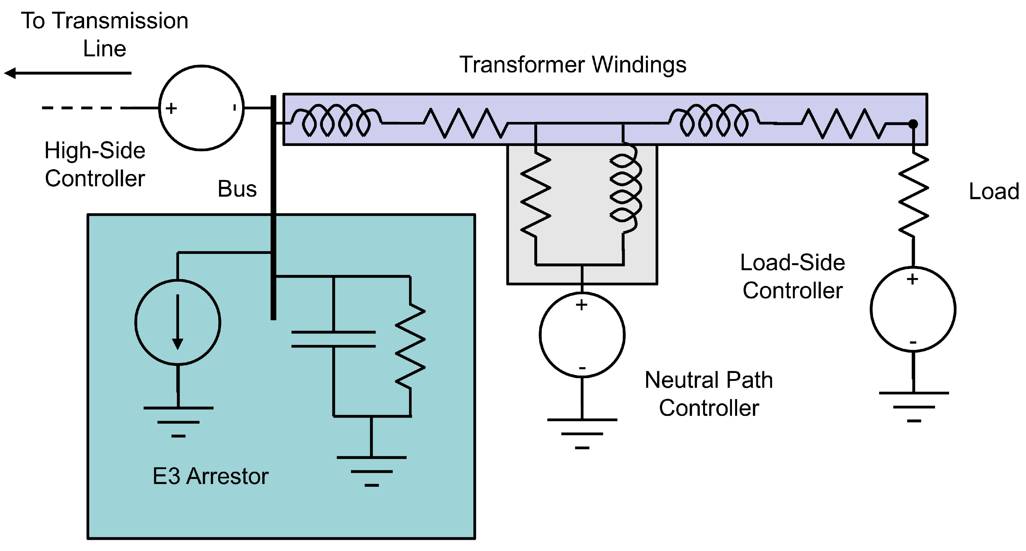
Figure 2.
Schematic of the per-phase model.
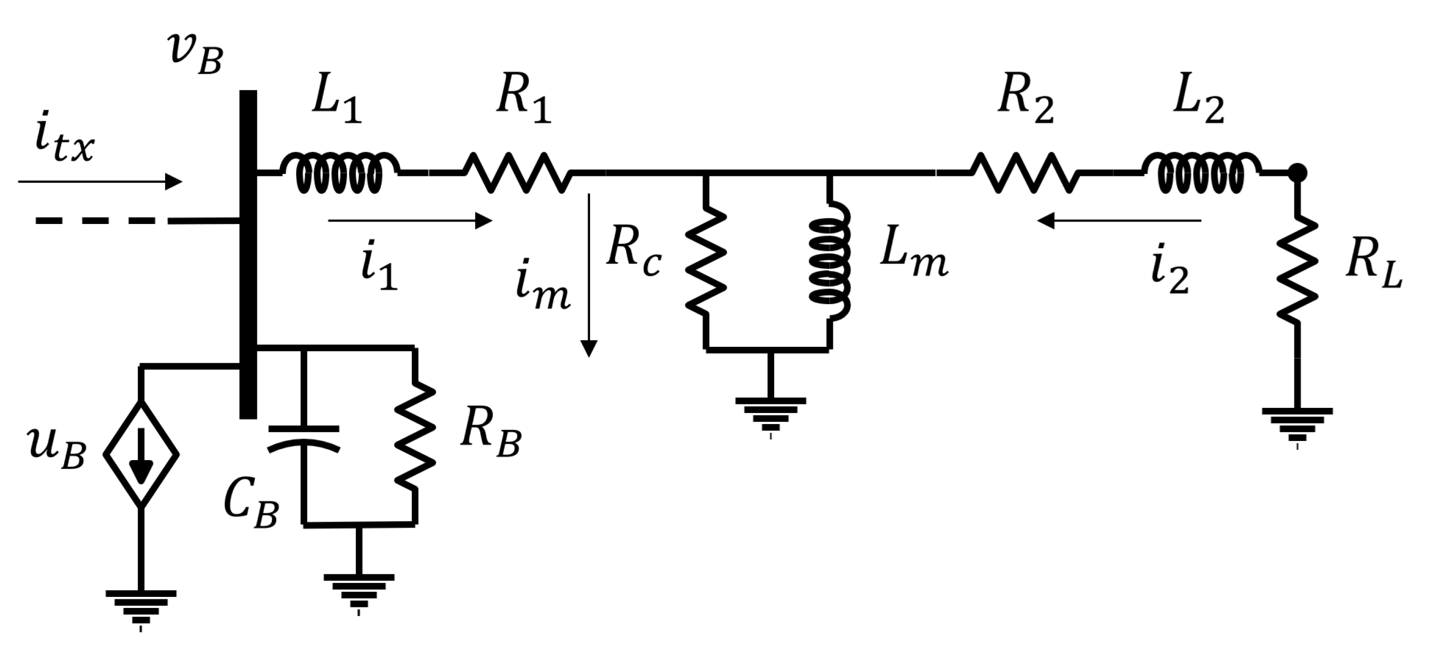
Figure 3.
Plot of the curve generated by the per-phase model in (2).
Figure 3.
Plot of the curve generated by the per-phase model in (2).
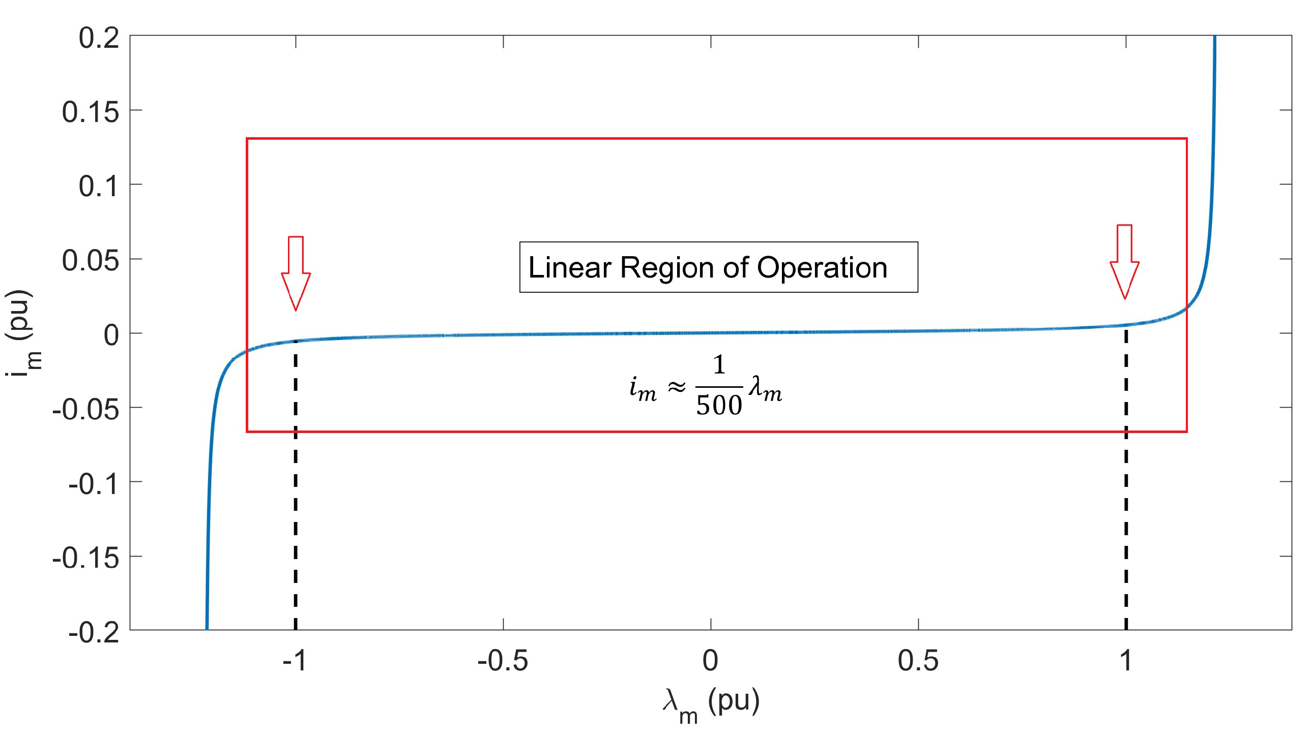
Figure 4.
The 18-bus model described in section 2.2. Substations are numbered. The bus configuration can be found in [25].
Figure 4.
The 18-bus model described in section 2.2. Substations are numbered. The bus configuration can be found in [25].
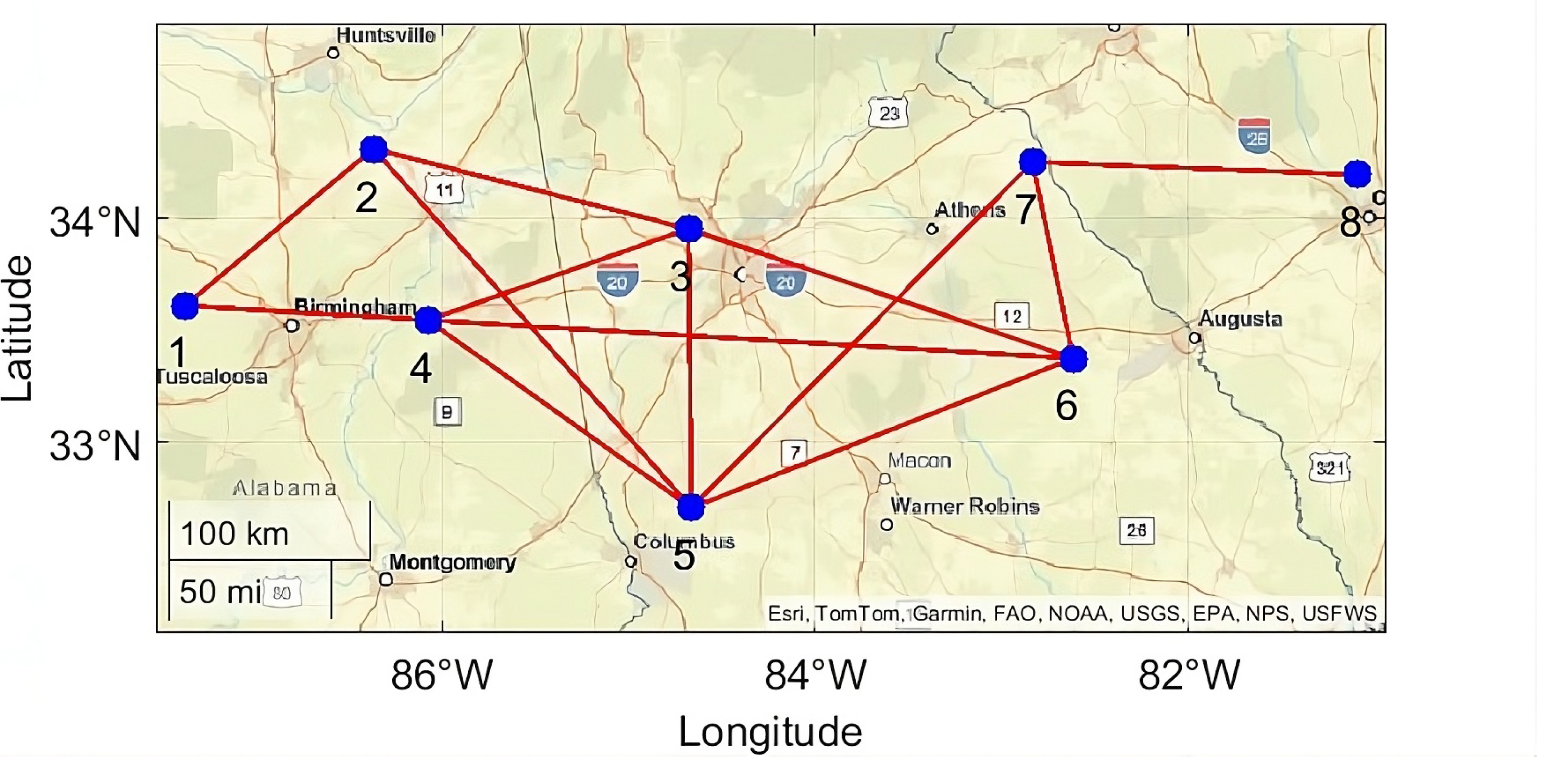
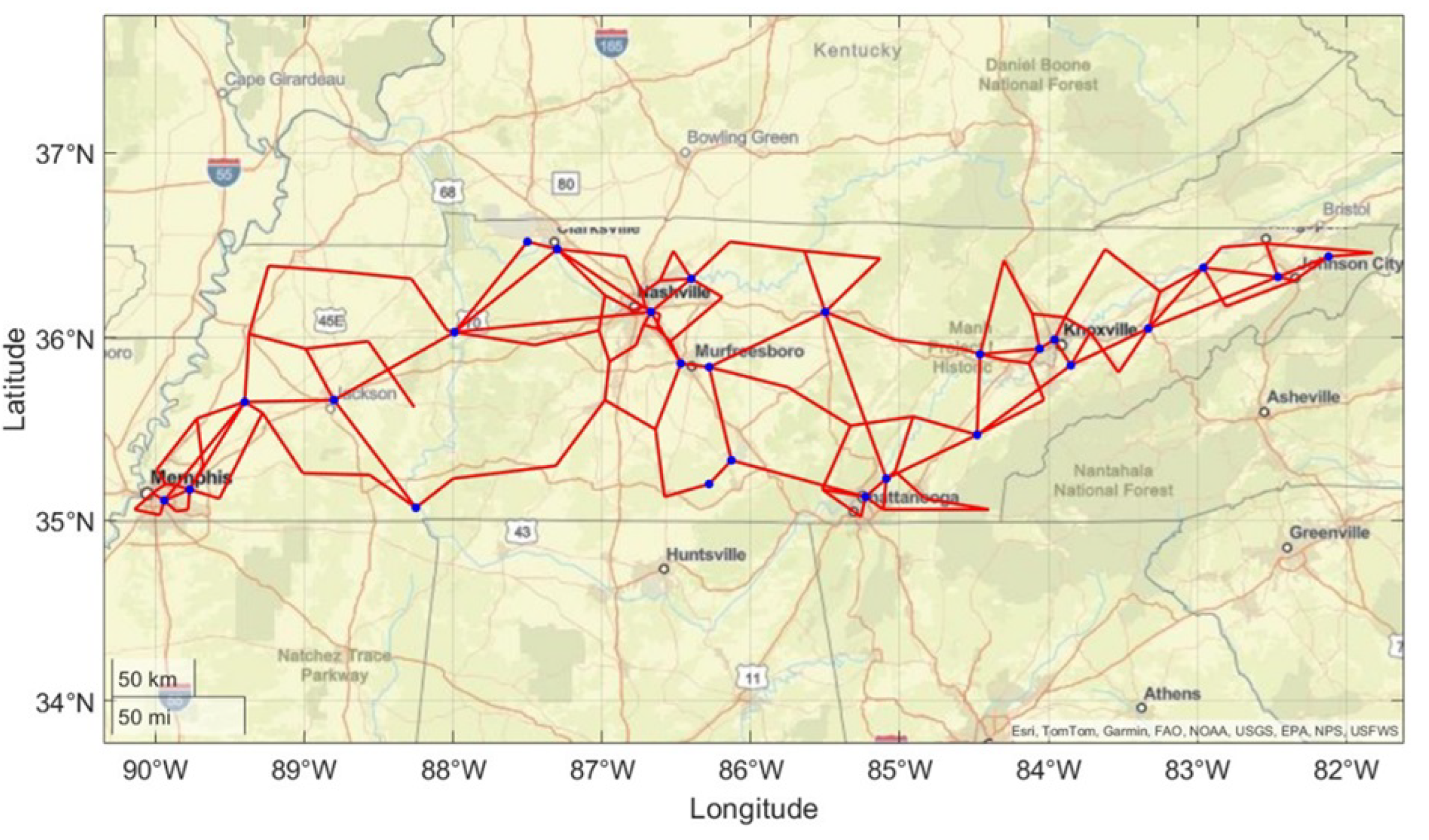
Figure 6.
Depiction of the field waveform magnitude. The equations for the waveforms are given in (3) and (4) [24].
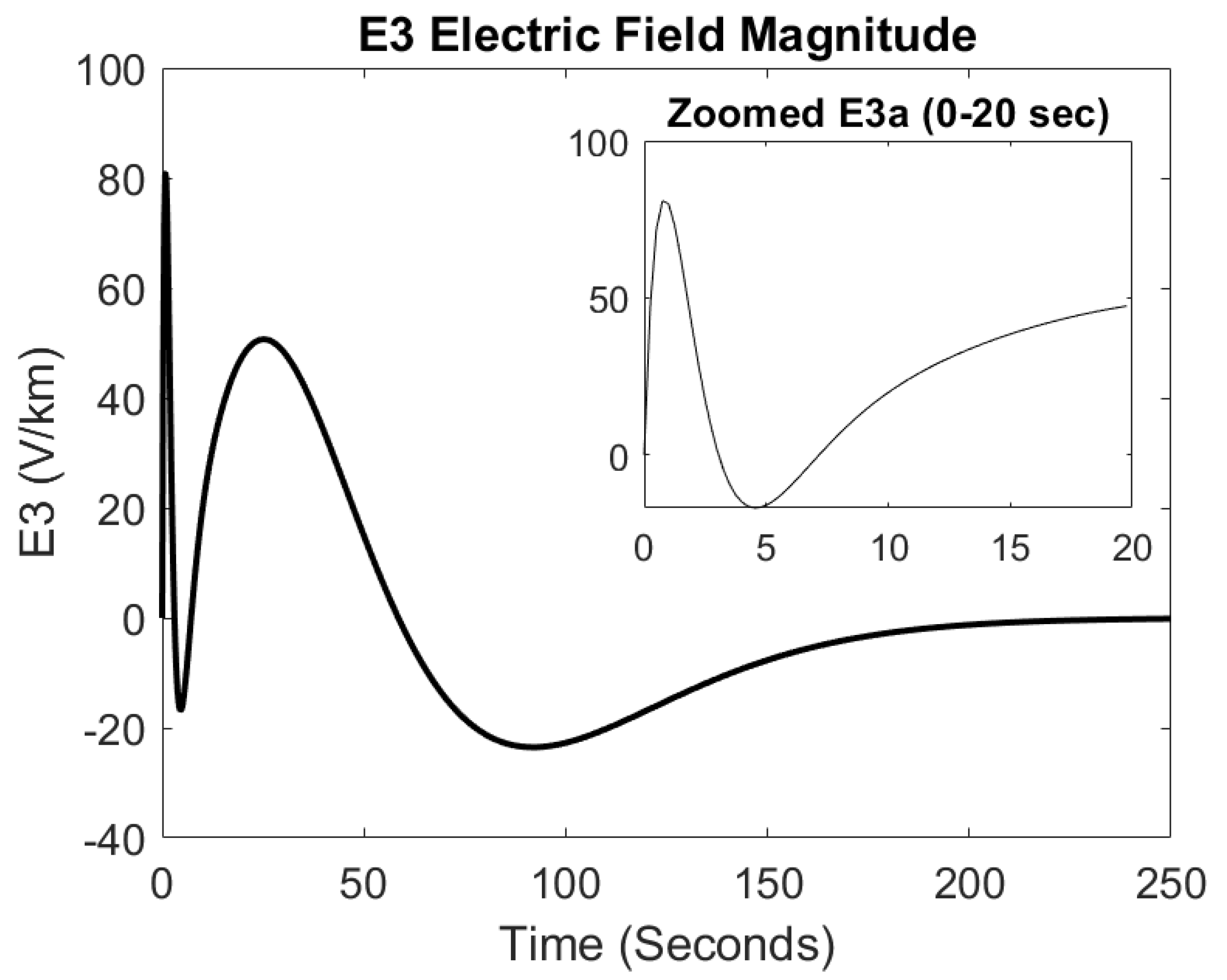
Figure 7.
Flowchart of the Minimum Subset Vertex Cover algorithm.
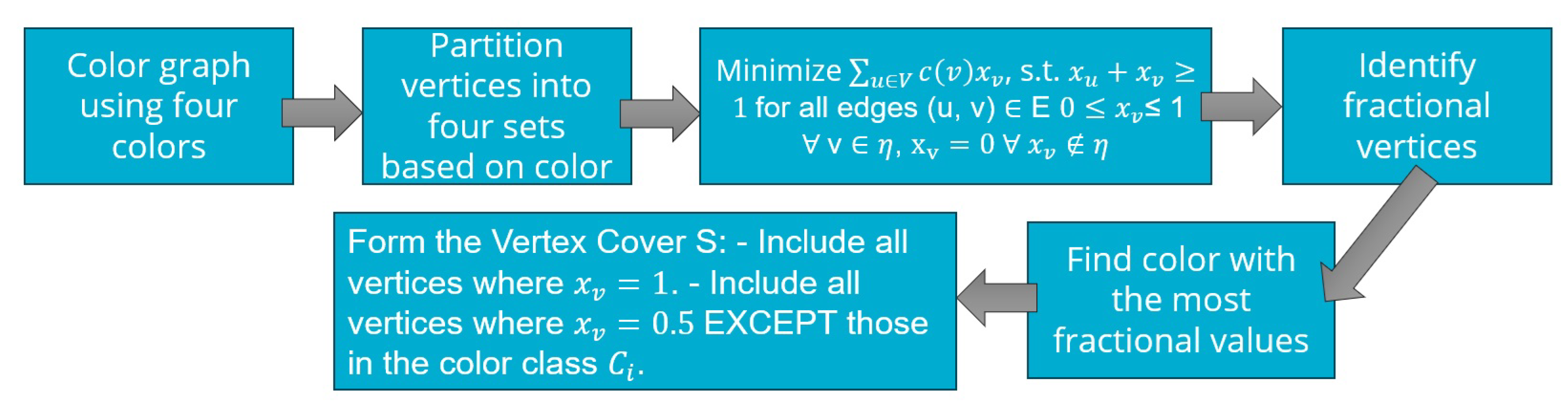
Figure 8.
Genetic algorithm for the placement of arrestor devices. With a cutoff point of , the GA was able to find a solution of 4 device placements.
Figure 8.
Genetic algorithm for the placement of arrestor devices. With a cutoff point of , the GA was able to find a solution of 4 device placements.
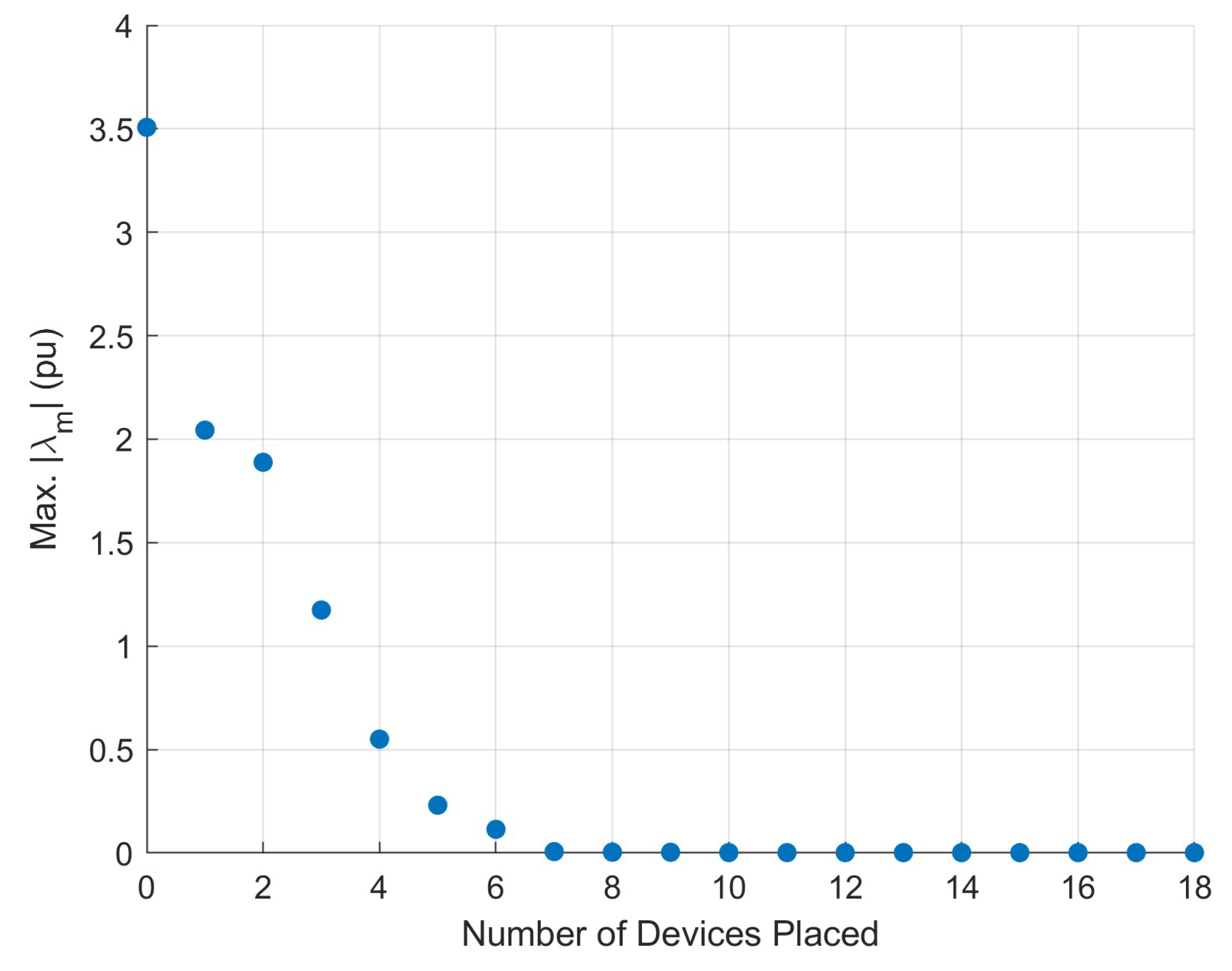

Table 1.
Absolute values of worst flux across all 16 field orientations, in pu.
| Controller Count | 3 | 4 | 5 | 6 | 7 | 8 |
|---|---|---|---|---|---|---|
| Worst || (pu) | 0.9053 | 0.6239 | 0.6065 | 0.4990 | 0.3295 | 0.2802 |
| Controller Count | 9 | 10 | 11 | 12 | 13 | 14 |
| Worst || (pu) | 0.1466 | 0.1364 | 0.0960 | 0.0925 | 0.0491 | 0.0487 |
| Controller Count | 15 | 16 | 17 | 18 | ||
| Worst || (pu) | 0.0486 | 0.0486 | 0.0486 | 0.0308 |
Disclaimer/Publisher’s Note: The statements, opinions and data contained in all publications are solely those of the individual author(s) and contributor(s) and not of MDPI and/or the editor(s). MDPI and/or the editor(s) disclaim responsibility for any injury to people or property resulting from any ideas, methods, instructions or products referred to in the content. |
© 2026 by the authors. Licensee MDPI, Basel, Switzerland. This article is an open access article distributed under the terms and conditions of the Creative Commons Attribution (CC BY) license (http://creativecommons.org/licenses/by/4.0/).
Copyright: This open access article is published under a Creative Commons CC BY 4.0 license, which permit the free download, distribution, and reuse, provided that the author and preprint are cited in any reuse.