

Submitted:
28 October 2026
Posted:
30 October 2026
You are already at the latest version
Abstract
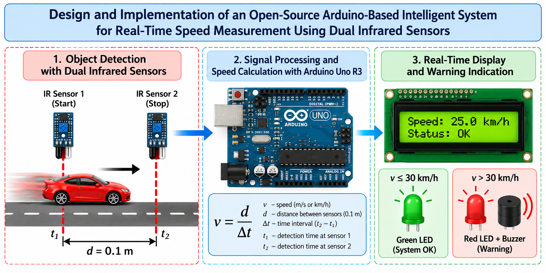
This paper presents the design and implementation of an integrated electronic system based on the open-source Arduino Uno platform for real-time speed measurement of different moving objects. The system integrates two infrared (IR) sensors, an Arduino Uno microcontroller, a liquid crystal display (LCD), light-emitting diodes (LEDs), and an acoustic buzzer, providing a functional, low-cost, and extensible solution. The proposed measurement method employs two IR sensors positioned alongside the object’s movement trajectory at a known separation distance. The microcontroller records the detection times at both sensors and calculates the object’s average speed over the sensing interval using the measured time difference and the predefined distance. The calculated speed is displayed on the LCD, while exceeding a configurable speed threshold activates visual and acoustic warning signals. A functional prototype was developed and tested under laboratory conditions using a fixed sensor separation of 0.1 m and different moving objects, including battery-powered toy vehicles, moving spheres, and human passage. Laboratory demonstrations confirmed the operation of the detection, speed calculation, and warning functions for the tested scenarios. The primary contribution of this work is the design and integration of accessible electronic components and open-source technologies into a reproducible speed-monitoring system. Its modular architecture and modifiable software provide opportunities for further development and adaptation to educational, laboratory, industrial, and motion-monitoring applications.
Keywords:
Arduino Uno
; infrared sensors
; speed measurement
; microcontroller
; embedded system
; real-time monitoring
; LCD
; LED
; buzzer
1. Introduction
The measurement and monitoring of the speed of moving objects are important tasks in various engineering and technological applications, including traffic monitoring, industrial automation, motion analysis, and experimental education. In urban environments, speed monitoring is particularly relevant to road safety, especially in areas near schools, hospitals, and pedestrian crossings. In industrial settings, speed measurement can support the monitoring of moving products, conveyor systems, and automated processes. These applications create a need for accessible electronic systems capable of detecting moving objects, estimating their speed, and providing timely information or warning signals.
Recent developments in microcontroller-based technologies have facilitated the design of compact, programmable, and cost-effective electronic monitoring systems. Open-source platforms, particularly Arduino, provide accessible hardware and software environments for integrating sensors, processing measurement signals, and controlling peripheral devices. Previous studies have demonstrated the applicability of Arduino-based systems in home automation, sensor monitoring, electronic measurement, and automated control applications [1,2,3,4,5,7,10,12,13]. The availability of standardized input/output interfaces, software libraries, and development tools makes these platforms suitable for rapid prototyping, experimental research, and educational applications.
Infrared (IR) sensors are frequently employed in electronic systems for detecting the presence and movement of objects without requiring direct physical contact. Their operating principles and performance characteristics have been investigated in studies addressing infrared sensing technologies, object detection, and sensor-based automation [14,16,17,20,29,30,31,32]. Owing to their relatively simple interfacing and compatibility with microcontrollers, IR sensors can be incorporated into monitoring systems that respond to the passage of objects. Their performance, however, depends on factors such as sensor alignment, target reflectivity, ambient illumination, and detection characteristics, which must be considered when designing reliable measurement configurations.
Several studies have investigated the use of infrared sensors and Arduino-based platforms for speed detection and measurement [43] examined an Arduino Uno-based approach to overspeed detection using an infrared sensor [18] investigated an IR-based traffic-light system, illustrating the relevance of infrared detection in traffic-related applications [45] also addressed vehicle speed detection using IR sensors [44] presented an Arduino Uno-based infrared sensor system for average-speed measurement in uniform linear motion experiments, with an emphasis on supporting physics education. Collectively, these studies demonstrate the relevance of combining infrared sensing and microcontroller-based processing for motion-related applications.
Beyond speed monitoring, the integration of microcontrollers with sensors and peripheral devices has been explored in other automated systems, including intelligent braking, electronic taximeters, and sensor-based control applications [8,9,15]. These investigations illustrate the broader potential of programmable electronic architectures for implementing event detection, measurement processing, and automatic responses. Nevertheless, the practical design of a speed-measurement prototype also requires attention to the coordination of sensing elements, timestamp acquisition, speed calculation, information display, and warning mechanisms within a reproducible hardware and software configuration.
A straightforward approach to estimating the average speed of a moving object is to detect its passage at two spatially separated positions. If the distance between the detection points is known, the average speed can be calculated from the elapsed time between the two detection events. In a microcontroller-based implementation, the use of hardware interrupts can facilitate the recording of detection timestamps and reduce dependence on continuous sensor-state polling in the main program loop. This measurement principle provides a practical basis for developing an integrated system that combines object detection, time-interval acquisition, numerical computation, and automatic indication of predefined operating conditions.
Despite the demonstrated potential of Arduino-based sensing systems, an important practical consideration is the integration of these functions into a modular and accessible prototype that can be reproduced and adapted for different experimental scenarios. In particular, combining two infrared sensors with interrupt-based timestamp acquisition, an LCD for real-time speed visualization, and LED and buzzer indicators for threshold-based warnings offers a compact approach to demonstrating the relationship between object motion, time measurement, and automated electronic control. The present study addresses this design objective by developing an open-source Arduino-based system for measuring and monitoring the average speed of moving objects.
The primary objective of this research is to design, implement, and demonstrate a low-cost electronic prototype based on an Arduino Uno R3 microcontroller and two infrared sensors positioned at a fixed separation distance. The system records the detection timestamps, calculates the average speed of a moving object, displays the resulting value on a 16 × 2 liquid crystal display (LCD), and activates visual and audible warnings when the calculated speed exceeds a predefined threshold. In the implemented configuration, the distance between the sensors is 0.1 m, and the warning threshold is set to 30 km/h. The software is developed in C/C++ using the Arduino Integrated Development Environment (IDE), with external hardware interrupts used to register the sensor detection events.
The main contribution of this study is the design and functional integration of object detection, interrupt-based timestamp acquisition, speed calculation, real-time display, and automatic warning generation within a single modular electronic prototype. The developed system was demonstrated under laboratory conditions using battery-powered toy vehicles, moving spheres, and human passage. These demonstrations were intended to establish the basic operational feasibility of the proposed architecture rather than to provide a quantitative assessment of metrological accuracy. Accordingly, the study presents a reproducible design and implementation approach while identifying the need for further validation against calibrated reference instruments.
The remainder of this paper is organized as follows. Section 2 describes the materials and methods, including the electronic components, circuit configuration, and software implementation. Section 3 presents the implementation results and functional demonstrations. Section 4 discusses the findings, practical limitations, and opportunities for further development. Finally, Section 5 summarizes the principal conclusions and outlines potential applications and future research directions.
2. Materials and Methods
The design and implementation of the proposed intelligent digital system for measuring the speed of moving objects involved the integration of several electronic components, including an Arduino Uno R3 microcontroller, infrared (IR) sensors, a buzzer, a liquid crystal display (LCD), a 5 V DC power supply, a breadboard, light-emitting diodes (LEDs), resistors, and jumper wires for establishing the necessary electrical connections [13,14,15]. The coordination and interaction of these components are managed by dedicated software developed in the C++ programming language using the Arduino Integrated Development Environment (IDE).
The primary scientific contribution of this study lies in the design, development, and implementation of an integrated, modular, and cost-effective electronic system based on the open-source Arduino Uno platform for real-time speed measurement and monitoring of various moving objects. The proposed system incorporates two infrared (IR) sensors positioned alongside the object's trajectory at a predefined separation distance. These sensors are interfaced with a microcontroller that utilizes hardware interrupts to capture detection timestamps and calculate the average speed of the moving object over the sensing interval.
The calculated speed is displayed on the LCD, while exceeding a predefined speed threshold automatically triggers visual warnings through LEDs and an audible alarm through the buzzer. This integrated approach combines object detection, time-interval measurement, speed computation, real-time data visualization, and automated warning functions within a single embedded system.
The main significance of the proposed solution lies in the integration of readily available and programmable electronic technologies into a functional, reproducible, and extensible system. The developed prototype was demonstrated under laboratory conditions using different types of moving objects, including battery-powered toy vehicles, moving spheres, and human passage. These demonstrations support the practical feasibility of the proposed system for the tested scenarios.
Furthermore, the modular architecture and open-source development environment provide opportunities for future improvements, functional extensions, and adaptation to a wider range of applications. The proposed system may serve as a foundation for further research and development in embedded systems, automation, motion monitoring, and practical education in electronics and microcontroller programming.
Arduino Uno R3
The Arduino Uno R3 is a microcontroller development board based on the ATmega328P microcontroller and represents one of the most widely adopted platforms within the Arduino ecosystem. Essentially, the Arduino Uno R3 is a compact electronic circuit board designed to execute programmed instructions and communicate with external electronic devices through its digital and analog input/output interfaces, as illustrated in Figure 1 [3,4,5,16,42].
The Arduino Uno R3 is characterized by its ease of use, accessibility, and straightforward programming through the Arduino Integrated Development Environment (IDE). Its extensive collection of software libraries and broad community support further contribute to its widespread adoption in educational, research, and prototyping applications.
The board provides 14 digital input/output pins, six of which support pulse-width modulation (PWM), and six analog input pins that enable the acquisition of signals from various electronic components, including sensors, microswitches, push buttons, and other peripheral devices. It also incorporates a USB interface for communication with a computer, an external power input, and a 16 MHz quartz crystal oscillator [21,22].
The open-source hardware architecture of the Arduino Uno R3 has facilitated the development and production of numerous compatible boards and alternative implementations. Despite differences in manufacturing and component configurations, these variants generally retain the fundamental programming principles and peripheral interfacing characteristics of the original platform [17,18,19].
One of the principal advantages of the Arduino Uno R3 is its extensive ecosystem of software libraries and predefined functions, which facilitates the development of applications ranging from elementary electronic circuits to relatively complex embedded systems. For example, simple programs can be developed to control the blinking frequency of light-emitting diodes (LEDs), while more advanced implementations may incorporate temperature, humidity, and hazardous gas monitoring systems, robotic devices, and interactive electronic installations.
Furthermore, the platform supports the integration of additional communication and display modules, including Bluetooth, Wi-Fi, Ethernet, and liquid crystal displays (LCDs). These expansion capabilities significantly enhance its flexibility and suitability for a wide range of electronic monitoring, control, and automation applications [1,2,3,4,5,24,25,26,27].
The Arduino Uno R3 operates at a nominal logic voltage of 5 V DC, a commonly used voltage level in electronic systems, which facilitates interfacing with numerous compatible sensors, actuators, and peripheral components. Programming is performed using the Arduino programming framework, which is based on the C/C++ programming languages and provides simplified functions and libraries to support both novice and experienced developers.
A USB connection enables communication between the board and a computer and allows compiled programs, commonly referred to as sketches, to be uploaded to the microcontroller. The Arduino IDE provides an accessible development environment for writing, compiling, and uploading these programs. Once uploaded, the microcontroller executes the programmed instructions continuously according to the implemented control logic, provided that an appropriate power supply is maintained and the device remains operational.
Another important factor contributing to the popularity of the Arduino Uno R3 is its extensive international developer community. Numerous open-source software libraries, practical examples, technical tutorials, and troubleshooting resources are publicly available, facilitating the implementation of diverse electronic and embedded-system applications.
In educational environments, the Arduino Uno R3 provides an effective platform for practical learning in electronics, programming, microcontroller interfacing, and automated control systems. Its accessibility and relatively low implementation cost enable students to develop practical skills through experimental activities involving sensors, actuators, and electronic circuits [2,3,4,5,29,30,31,32].
In industrial and engineering contexts, the Arduino Uno R3 is frequently employed for rapid prototyping and preliminary proof-of-concept development. It enables engineers and researchers to evaluate electronic designs, investigate control strategies, and test innovative concepts before transitioning to more specialized hardware platforms, thereby reducing the time and cost associated with early-stage system development.
Breadboard
A breadboard, also referred to as a prototyping board or protoboard, is an essential tool for the rapid assembly, testing, and modification of electronic circuits without requiring soldering [23,34]. It provides a reusable and flexible platform for developing experimental circuits, allowing electronic components to be interconnected, repositioned, and replaced during the prototyping process.
Structurally, a breadboard consists of numerous small insertion holes arranged in rows and columns. Beneath its insulating surface, these holes are interconnected through conductive metal strips, enabling electrical continuity between component terminals inserted into the same electrically connected group, as illustrated in Figure 2.
- Terminal strips and interconnected contact groups: A typical breadboard is divided into several sections containing rows or columns of electrically connected contact points. Each group is internally connected by a conductive metal strip. When a component lead or connecting wire is inserted into one of these holes, an electrical connection is established with the other holes belonging to the same contact group. This arrangement facilitates the construction of electronic circuits without permanent electrical joints.
- Power distribution rails: Breadboards commonly incorporate dedicated power rails along their edges, typically identified by the symbols “+” and “−”. These rails are used to distribute supply voltages, such as 5 V DC or 3.3 V DC, and the corresponding ground reference (GND) throughout the circuit. This arrangement simplifies power distribution among multiple electronic components, reduces the number of individual connecting wires, and contributes to a more organized circuit configuration.
- Relevance to Arduino-based applications: Breadboards are particularly suitable for prototyping electronic systems based on Arduino development boards, which provide digital and analog input/output interfaces and commonly operate with 5 V or 3.3 V logic levels, depending on the board model. By positioning a breadboard near the Arduino board and establishing connections through jumper wires, electronic components such as resistors, light-emitting diodes (LEDs), infrared (IR) sensors, and other peripheral devices can be conveniently integrated into the experimental circuit. The required electrical connections are established between the breadboard contact points and the corresponding Arduino pins.
Importance and Advantages of Breadboards
- Rapid circuit assembly and modification: Breadboards enable electronic circuits to be assembled and modified quickly without soldering or other permanent connection methods. Components and connecting wires can be repositioned immediately, significantly reducing development time and facilitating iterative experimentation.
- Flexibility in reconfiguration and troubleshooting: The solderless construction allows electronic components to be removed, replaced, or relocated without damaging the circuit assembly. This characteristic is particularly advantageous during the early stages of prototype development, when circuit configurations may require repeated adjustments, testing, and optimization.
- Improved safety and workspace organization: By eliminating the need for soldering during initial prototyping, breadboards reduce exposure to soldering-related hazards, including thermal burns and potential heat-induced damage to electronic components. Furthermore, their structured arrangement of contact points and power rails facilitates systematic wiring, improves circuit accessibility, and supports a cleaner and more organized experimental workspace.
Overall, the breadboard represents a practical and cost-effective solution for developing and evaluating electronic prototypes. Its reusability, ease of modification, and compatibility with standard electronic components make it particularly valuable in educational laboratories, embedded-system development, and Arduino-based experimental applications.
Infrared (IR) Sensor
Infrared (IR) sensors are widely used electronic devices for detecting the presence, movement, and proximity of objects. Depending on the sensor type, operating principle, and technical specifications, their detection range may extend from approximately 30 cm to 10 m, as illustrated in Figure 3 [17,18,19].
The operating principle of an active reflective IR sensor is based on the emission and reception of infrared radiation, which lies outside the visible spectrum of the human eye. The sensor emits infrared radiation toward a target area, and a portion of this radiation is reflected by an object and subsequently detected by the receiving element. When a moving object enters the detection region, the intensity of the reflected radiation changes, producing a corresponding change in the sensor's output signal. This signal can be acquired and processed by a microcontroller to identify the presence or passage of an object [32].
When an object passes through the sensing region, the reflected infrared radiation is detected by the receiver, allowing the sensor to generate an electrical signal indicating a detection event. The microcontroller interprets this signal as an indication that an object has entered or passed through the monitored region. The emission and reflection of infrared radiation during object detection are illustrated in Figure 4 [20].
IR sensors are extensively employed in electronic monitoring and automation applications, including robotic obstacle detection, security alarm systems, automatic doors, and infrared-based remote-control systems. Their widespread use is associated with their relatively simple integration, low cost, and ability to detect objects without physical contact [43,44].
In applications involving the measurement of moving-object speed, two IR sensors can be positioned at a predefined separation distance along the object's trajectory. Each sensor detects the passage of the moving object at a different instant, allowing the elapsed time between the two detection events to be determined. By combining this time interval with the known distance between the sensors, the average speed of the moving object can be calculated [45].
Another important advantage of IR sensors is their relatively low power consumption and compatibility with commonly used microcontroller platforms. Depending on the sensor model, these devices typically operate at supply voltages of 5 V DC or lower and can provide stable operation under suitable environmental conditions [30,31,32].
Nevertheless, the performance of reflective IR sensors may be influenced by external factors, including strong ambient illumination, interference from other infrared sources, the reflective properties of the target surface, and the relative positioning of the sensor and moving object. Consequently, appropriate sensor selection, positioning, and calibration are important considerations when implementing IR-based detection systems.
When interfaced with an Arduino Uno microcontroller, IR sensors enable the development of electronic systems capable of responding automatically to changes in the monitored environment. Their straightforward integration with digital input interfaces makes them suitable for experimental applications involving object detection, motion monitoring, and automated control.
In the proposed study, two active IR sensors were employed to detect the passage of moving objects and determine their average speed. The sensors were positioned alongside the movement trajectory at a fixed separation distance of d = 0.1 m. The experimental configuration was designed to represent a speed-monitoring scenario with a predefined speed limit of 30 km/h, corresponding to a possible speed restriction in an urban traffic environment.
When a moving object passes the first sensor (IR1), the microcontroller records the initial detection time, denoted by t₁. As the object subsequently passes the second sensor (IR2), the second detection time, denoted by t₂, is recorded. These timestamps enable the calculation of the elapsed time between the two detection events and, consequently, the average speed of the moving object over the known sensor separation distance.
The fundamental relationship between speed, distance, and elapsed time is expressed as follows:
where:
- represents the average speed of the moving object;
- represents the distance traveled between the first and second detection points, corresponding to the sensor separation distance, which is d = 0.1 m in the proposed experimental configuration;
- represents the elapsed time between the detection events recorded by IR1 and IR2.
The time interval between the two consecutive detection events is calculated as:
where t₁ and t₂ denote the detection timestamps recorded by the first and second IR sensors, respectively.
Accordingly, the average speed of the moving object is determined using:
For applications involving vehicle speed monitoring, the calculated speed is commonly expressed in kilometers per hour (km/h). Therefore, the conversion from meters per second to kilometers per hour is performed as follows:
where d is expressed in meters and Δt in seconds.
The conceptual arrangement of the two IR sensors alongside an urban roadway, where vehicle speed is restricted to 30 km/h, is illustrated in Figure 5.
In the considered application scenario, the predefined maximum permissible speed is:
An overspeed condition is identified when: .
The speed calculated by the microcontroller is converted into kilometers per hour and displayed on the LCD screen. When the measured speed exceeds the predefined threshold of 30 km/h, the system automatically activates visual and audible warning mechanisms through the corresponding LED indicator and buzzer.
Within the proposed system, the IR sensors serve as the primary detection elements, providing the temporal information required for speed estimation. Their integration with the Arduino Uno microcontroller enables the implementation of a low-cost, modular, and programmable speed-monitoring prototype.
The use of two spatially separated IR sensors, together with hardware-interrupt-based timestamp acquisition, provides a practical approach to estimating the average speed of moving objects under controlled experimental conditions. However, the measurement accuracy and reliability depend on sensor response characteristics, detection consistency, timing resolution, and environmental conditions. Further experimental validation against a reference measurement system would be required to quantify measurement uncertainty and establish the suitability of the proposed approach for practical traffic-monitoring applications [43,44,45].
16 × 2 LCD Display
The 16 × 2 Liquid Crystal Display (LCD) is a widely used alphanumeric display module capable of presenting up to 16 characters per row across two rows, providing a total display capacity of 32 characters. This type of display is commonly employed in electronic and Arduino-based applications because it offers a simple and efficient means of presenting real-time information without requiring a continuously connected computer [27,28,33]. Owing to its affordability, ease of integration, and relatively low power consumption, the 16 × 2 LCD is frequently incorporated into applications ranging from educational electronic projects to professional prototypes, as illustrated in Figure 6.
The primary component of the display is the liquid crystal panel, which is designed to present alphanumeric information, including numerical values, letters, and selected symbols, through a matrix of individually controlled pixels. This configuration enables the display of measurement results, system operating conditions, and short informational messages in a clear and structured format.
Communication between the LCD module and an Arduino board or another microcontroller is typically established through digital interface pins responsible for transmitting commands and character data. In conventional parallel-interface configurations, the display can operate in either 4-bit or 8-bit mode. The 4-bit operating mode requires fewer microcontroller input/output pins than the 8-bit mode, making it particularly advantageous in embedded applications where the availability of digital pins is limited.
Regarding power requirements, these LCD modules commonly operate with a 5 V DC supply, although certain variants are designed for operation at 3.3 V. A ground connection (GND) is also required to establish the electrical reference for the circuit. The display typically includes provisions for backlight control and contrast adjustment. The contrast can be regulated using a small potentiometer, allowing the visibility of the displayed characters to be optimized according to the operating conditions.
An important advantage of the 16 × 2 LCD module is its widespread compatibility with microcontroller development platforms and the availability of extensive technical documentation and software libraries. For Arduino-based systems, libraries such as LiquidCrystal simplify display initialization, cursor positioning, and the presentation of numerical and textual information, thereby reducing software development complexity.
Although the 16 × 2 LCD is not intended for advanced graphical visualization or the presentation of complex images, it provides an effective and reliable interface for applications requiring the display of numerical measurements, operating states, and short notification messages. Consequently, it is particularly suitable for electronic monitoring and control systems in which compactness, simplicity, and efficient information presentation are important design considerations [19,20,21].
Buzzer
A buzzer is an electronic component widely used for audible signaling in various applications, including basic alarm systems, safety warnings, and operational status notifications, as illustrated in Figure 7 [15,39,40,41].
The fundamental operating principle of a buzzer involves converting electrical signals into acoustic energy, typically producing audible beeps or warning tones at specific frequencies. Buzzers are generally classified into two main categories: active and passive.
An active buzzer incorporates an internal oscillator circuit that generates the required acoustic frequency. Consequently, it produces an audible signal when an appropriate DC supply voltage is applied. In Arduino-based applications, an active buzzer can be controlled through a digital output pin, provided that its operating voltage and current requirements are compatible with the microcontroller's electrical specifications.
In contrast, a passive buzzer requires an externally generated periodic electrical signal to produce sound. In this configuration, the microcontroller generates an appropriate waveform, such as a pulse-width-modulated (PWM) signal or another periodic signal, to drive the buzzer at the desired frequency.
The integration of buzzers into Arduino-based electronic systems is relatively straightforward. For active buzzers, a microcontroller pin can be configured as an output using the pinMode() function, while the digitalWrite() function can be employed to control its operating state. Setting the output to HIGH (approximately 5 V for an Arduino Uno R3) or LOW (approximately 0 V) enables or disables the audible signal, depending on the buzzer configuration and driving circuit. For passive buzzers, the Arduino tone() function can be used to generate a periodic signal at a specified frequency.
These characteristics make buzzers particularly suitable for applications requiring immediate audible feedback or warning notifications. For example, in an electronic speed-measurement system, the buzzer can be activated automatically when the calculated speed of a moving object exceeds a predefined threshold [41,42].
Another significant advantage of buzzers is their compact size, relatively low cost, and generally modest power consumption, which facilitate their integration into electronic prototypes and embedded systems. Depending on their electrical and acoustic specifications, buzzers can generate audible signals that are clearly perceptible in indoor environments and, under suitable conditions, in outdoor applications. Various buzzer models are available with different sound pressure levels, operating frequencies, and voltage requirements, allowing appropriate selection according to specific application needs.
In electronic monitoring and control systems, buzzers serve as important signaling devices for attracting the user's attention when predefined operating conditions are detected. Such conditions may include exceeding a temperature threshold, detecting the presence of an object, or identifying a vehicle traveling above the permitted speed limit in an urban environment.
Accordingly, buzzers represent practical components in a broad range of electronic applications, from elementary Arduino-based projects to more sophisticated industrial and laboratory alarm systems. Their simplicity, affordability, and ability to provide immediate audible notifications make them particularly valuable in automated monitoring and warning applications.
LED (Light-Emitting Diode)
A light-emitting diode (LED) is one of the most important and widely used electronic components in electronic circuit design, particularly in applications based on the Arduino platform. From a functional perspective, an LED is a semiconductor diode that emits light when an electric current flows through it under forward-bias conditions. Its internal structure is based on semiconductor materials, such as gallium arsenide (GaAs), gallium phosphide (GaP), and other suitable semiconductor compounds. Light emission occurs through the recombination of electrons and holes within the semiconductor junction, releasing energy in the form of photons [26,27]. This physical phenomenon, known as electroluminescence, enables LEDs to function as highly efficient light sources compared with conventional incandescent lamps, as illustrated in Figure 8.
From an electronic engineering perspective, an LED has two primary terminals: the anode (positive terminal) and the cathode (negative terminal). In conventional through-hole LEDs, the anode is typically identified by the longer lead, whereas the cathode is generally associated with the shorter lead. An essential operating characteristic of an LED is that it must be forward-biased to emit light. Under reverse-bias conditions, the diode substantially restricts current flow within its specified operating limits.
To regulate the current flowing through an LED and prevent potential damage, a current-limiting resistor is typically connected in series with the component. This resistor restricts the current to a level compatible with the LED's electrical specifications, thereby ensuring safe and stable operation. Without adequate current limitation, excessive current may flow through the LED, potentially causing overheating, permanent component failure, or damage to other elements of the electronic circuit.
Resistors
Resistors play a fundamental role not only in light-emitting diode (LED) circuits but also in a wide range of electronic applications. Their primary function is to provide electrical resistance, which is measured in ohms (Ω), as illustrated in Figure 9.
The selection of an appropriate resistance value, commonly referred to as a current-limiting resistance in LED applications, primarily depends on the following parameters:
- Supply voltage: The voltage provided by the power source, such as the 5 V output level of an Arduino Uno digital pin.
- LED forward voltage: The voltage drop across the LED under forward-bias conditions, typically ranging from approximately 2.0 to 3.5 V DC, depending on the LED type and semiconductor material.
- LED forward current: The permissible operating current of the LED, which commonly ranges from 10 to 20 mA for standard indicator LEDs, depending on their electrical specifications.
In Arduino-based electronic systems, LEDs are frequently employed as visual status indicators, for example, to confirm the execution of a particular function or to signal an alarm condition. They can also be integrated into more advanced applications, including LED matrix displays and electronic information panels.
Resistors, on the other hand, serve several additional functions beyond limiting the current flowing through LEDs. These include voltage division, signal conditioning, and filtering, as well as the implementation of timing circuits in combination with capacitors [16,17,19].
The resistance values of conventional through-hole resistors can be identified using standardized color-band coding systems, in which individual colored bands represent numerical digits, multipliers, and tolerance values according to established conventions [35,36,37,38].
From an educational and engineering perspective, LEDs and resistors represent fundamental components for understanding and experimenting with electronic circuits and microcontroller-based systems. Their combined use provides a practical demonstration of essential electrical and electronic principles, including voltage drop, current flow, polarity, forward bias, current limitation, and the prevention of component damage.
These fundamental concepts provide the basis for the development of a broad range of engineering applications, extending from educational electronic projects to industrial prototypes in which visual signaling and appropriate current regulation are essential for reliable operation and long-term system performance.
Jumper Wires
Jumper wires are small, flexible connecting wires specifically designed to establish electrical connections between electronic components or different sections of a circuit without requiring soldering. They are widely used during the prototyping stage, enabling designers to test and modify circuit configurations in a simple, flexible, and reversible manner.
Jumper wires are commonly employed in electronic projects involving breadboards, Arduino boards, Raspberry Pi platforms, and other microcontroller-based systems. They are also extensively used in educational and scientific laboratories, where students and researchers assemble and experiment with basic electronic circuits [35,36,37,38].
The main types of jumper wires are illustrated in Figure 10.
2.1. Arduino Integrated Development Environment (IDE)
The Arduino Integrated Development Environment (IDE) is a software development platform specifically designed for programming Arduino-compatible microcontroller boards, including the Arduino Uno. It was developed to simplify the processes of writing, compiling, and uploading program code to Arduino boards, thereby facilitating the development of embedded electronic applications for users with varying levels of programming and electronics expertise.
One of the principal advantages of the Arduino IDE is its extensive support for software libraries that extend the functionality of microcontroller-based applications. These libraries facilitate the integration and control of various peripheral devices, including sensors, liquid crystal displays (LCDs), wireless communication modules such as Wi-Fi and Bluetooth, electric motors, and other electronic components [3,4,5,6]. By providing reusable software functions and standardized interfaces, these libraries reduce implementation complexity and support efficient application development.
Another important feature of the Arduino IDE is the Serial Monitor, which enables real-time communication between the Arduino board and a connected computer. This functionality allows developers to observe data transmitted by the microcontroller during program execution, thereby supporting software debugging, system monitoring, and the analysis of measurement results. For instance, in an electronic speed-measurement system, the calculated speed values can be transmitted to the Serial Monitor for inspection, facilitating the verification of computational outputs and the identification of potential programming or operational issues.
Furthermore, the Arduino IDE is an open-source development environment supported by an extensive international community of developers, researchers, educators, and electronics enthusiasts. Its open-source architecture encourages continuous software improvement, the development of additional tools and libraries, and adaptation to specific application requirements. This collaborative development model promotes transparency, accessibility, and knowledge sharing, making the Arduino IDE a practical environment for educational, experimental, and research-oriented embedded systems.
2.2. Electronic Circuit Configuration Under Laboratory Conditions
Figure 11.
Electrical Wiring Diagram.
Electronic Circuit Configuration and System Operation
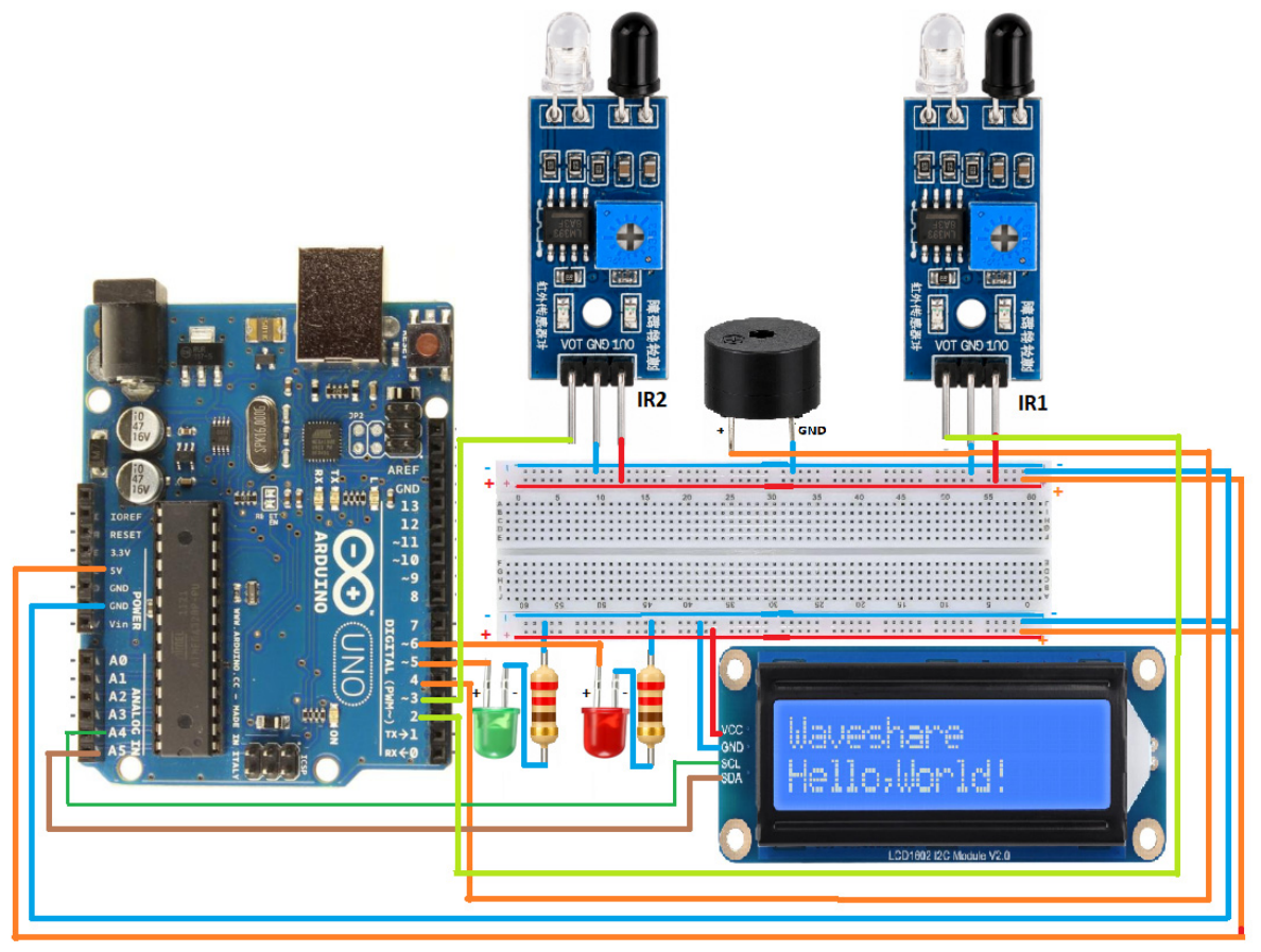
Figure 13 illustrates the electronic circuit configuration of an Arduino Uno-based system designed to measure the speed of moving objects passing in front of two infrared (IR) sensors under controlled laboratory conditions. The proposed intelligent electronic system integrates two IR sensors, a 16 × 2 liquid crystal display (LCD) with an I²C communication interface, an audible buzzer, and two light-emitting diodes (LEDs). These components collectively provide a functional prototype for speed measurement, real-time information display, and visual and audible warning generation.
As shown in the circuit diagram, the two IR sensors are connected to digital pins 2 and 3 of the Arduino Uno, corresponding to the external interrupt inputs INT0 and INT1, respectively. These connections enable the microcontroller to respond promptly to sensor activation events and record the corresponding timestamps. Interrupt-based event detection is particularly important in speed-measurement applications, where the time interval between consecutive sensor detections is used to calculate the average speed of a moving object.
The buzzer is connected to digital pin 4 and is activated when the calculated speed exceeds the predefined speed limit. Two LEDs, one green and one red, provide visual indications of the measured speed relative to the established threshold. The green LED illuminates when the measured speed remains within the permitted limit, whereas the red LED is activated when the speed exceeds this limit. Each LED is connected in series with a current-limiting resistor to regulate the current flowing through the component and protect both the LED and the Arduino output circuitry from excessive current.
The 16 × 2 LCD module communicates with the Arduino Uno through the I²C interface, using analog pins A4 and A5 as the serial data (SDA) and serial clock (SCL) lines, respectively. The display presents the calculated speed and, where applicable, informational or warning messages associated with the operating state of the system.
The proposed system may provide a basis for further development of speed-monitoring applications in environments where speed regulation is important, including areas near schools and hospitals. Potential applications also include laboratory experiments involving moving objects, selected sports-related measurements, and industrial processes in which speed monitoring is relevant. However, practical deployment in such environments would require additional experimental validation, sensor calibration, and evaluation under representative operating conditions.
Overall, the system represents a relatively simple, low-cost, and easily reproducible electronic prototype. Its modular architecture also provides opportunities for further development, including improved measurement accuracy, data acquisition and storage, and integration with more advanced notification and monitoring technologies.
Arduino Uno. The Arduino Uno serves as the central processing and control unit of the system. It executes the measurement algorithm, processes signals received from the IR sensors, calculates the speed of moving objects, and controls the LCD, buzzer, and LEDs. The board can be powered through its USB connection to a personal computer or through a suitable external power supply. The regulated 5 V supply is used to power compatible peripheral components, subject to the electrical and current limitations of the Arduino board.
Infrared (IR) Sensors. Each IR sensor module includes three primary connection terminals: VCC, GND, and OUT. The VCC terminal is connected to the 5 V DC supply, while the GND terminal provides the common electrical ground. The OUT terminal transmits a digital signal when the sensor detects a change associated with the presence or movement of an object within its detection region.
The first IR sensor (IR1) is connected to digital pin 2 of the Arduino Uno, whereas the second sensor (IR2) is connected to digital pin 3. These pins were selected because they support external hardware interrupts, enabling the microcontroller to detect sensor activation events and record their timestamps with reduced dependence on the execution timing of the main program loop. The recorded timestamps are subsequently used to determine the time interval required for the moving object to travel between the two sensor positions.
16 × 2 LCD with I²C Interface. The LCD module employs the Inter-Integrated Circuit (I²C) communication protocol, which requires two primary signal connections: SDA (Serial Data) and SCL (Serial Clock). On the Arduino Uno, these signals correspond to pins A4 and A5, respectively. The LCD module is also connected to the 5 V DC supply and the common ground (GND).
In the implemented software configuration, the LCD is addressed using the I²C address 0x27. However, this address may vary depending on the specific I²C interface module. The display provides real-time visualization of the calculated speed and relevant system status information.
Buzzer (Audible Warning Device). The buzzer has two electrical terminals. One terminal is connected to digital pin 4 of the Arduino Uno, while the other is connected to the common ground (GND). The buzzer is controlled by the microcontroller through an electrical output signal. Depending on the buzzer type, this may involve applying a digital output level or generating a periodic signal, such as a 1000 Hz tone.
When the calculated speed exceeds the predefined threshold, the program activates the buzzer to generate an audible warning. This functionality provides an additional notification mechanism that complements the visual warning produced by the red LED.
LEDs (Visual Warning Indicators). The system incorporates two LEDs, one green and one red, to indicate whether the measured speed is within or above the predefined limit.
The green LED is connected to digital pin 5 through a series current-limiting resistor, with its remaining terminal connected to GND. The resistor limits the forward current to a value compatible with the LED and the Arduino output pin specifications. The green LED illuminates when the calculated speed of the moving object is within the permitted range.
The red LED is connected to digital pin 6 of the Arduino Uno, also through a series current-limiting resistor, with the remaining terminal connected to GND. The red LED illuminates when the measured speed exceeds the predefined threshold, thereby providing an immediate visual indication of an overspeed condition.
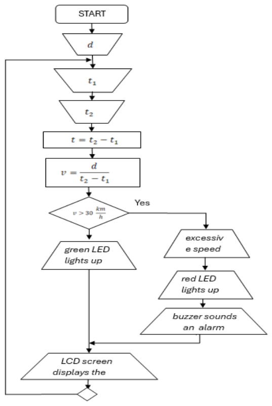
The complete electronic system operates according to the algorithm illustrated in Figure 14. The algorithm is implemented within a continuously executing program loop, while sensor detection events are handled through external interrupts. During operation, the system records the activation timestamps () and () associated with the passage of a moving object in front of sensors IR1 and IR2, respectively.
The time interval between the two detection events is subsequently determined as (). Using this interval and the known distance between the sensors, the system calculates the average speed of the moving object. The calculated value is displayed on the LCD and compared with the predefined speed limit to determine whether the green LED should remain illuminated or whether the red LED and buzzer should be activated.
Figure 12.
Flowchart of the Intelligent Digital System for Measuring the Speed of Objects in Linear Motion.
Figure 12.
Flowchart of the Intelligent Digital System for Measuring the Speed of Objects in Linear Motion.
2.3. Program Code
The program code is developed in the Arduino Integrated Development Environment (IDE) using the C++ programming language, following the programming structure, syntax, and conventions supported by the Arduino Uno platform. The software implementation is based on the electronic circuit configuration and the operational flowchart presented in Figure 13 and Figure 14, respectively. These diagrams provide the foundation for developing the program logic, ensuring consistency between the hardware connections, the measurement algorithm, and the functional requirements of the proposed system for measuring the speed of moving objects.
#include <Wire.h>
#include <LiquidCrystal_I2C.h>
#define SENSOR_1_PIN 2 // INT0
#define SENSOR_2_PIN 3 // INT1
#define BUZZER_PIN 4
#define GREEN_LED 5
#define RED_LED 6
// Timing and state variables
volatile unsigned long timeSensor1 = 0;
volatile unsigned long timeSensor2 = 0;
volatile bool sensor1Triggered = false;
volatile bool sensor2Triggered = false;
unsigned long lastBuzzerActivation = 0;
unsigned long greenLedStartTime = 0;
unsigned long redLedStartTime = 0;
bool buzzerActive = false;
// Configuration constants
const float distanceBetweenSensors = 0.1; // meters
const float speedLimit = 30.0; // km/h
const unsigned long debounceTime = 5000; // 5ms in microseconds
const unsigned long ledTimeout = 300; // 0.3 seconds
const unsigned long buzzerCooldown = 300; // 0.3 seconds cooldown period
float speed_kmh = 0;
LiquidCrystal_I2C lcd(0x27, 16, 2);
void setup() {
lcd.init();
lcd.backlight();
lcd.print(" Speed Gun ");
delay(1500);
lcd.clear();
// Use internal pull-ups if the sensor output is open-collector.
pinMode(SENSOR_1_PIN, INPUT_PULLUP);
pinMode(SENSOR_2_PIN, INPUT_PULLUP);
pinMode(BUZZER_PIN, OUTPUT);
pinMode(GREEN_LED, OUTPUT);
pinMode(RED_LED, OUTPUT);
// Use FALLING edge since INPUT_PULLUP makes the idle state HIGH.
attachInterrupt(digitalPinToInterrupt(SENSOR_1_PIN), sensor1ISR, FALLING);
attachInterrupt(digitalPinToInterrupt(SENSOR_2_PIN), sensor2ISR, FALLING);
digitalWrite(GREEN_LED, LOW);
digitalWrite(RED_LED, LOW);
}
void loop() {
handleSpeedCalculation();
updateBuzzerState();
updateLedState();
}
void handleSpeedCalculation() {
// Copy volatile variables atomically.
noInterrupts();
bool s1 = sensor1Triggered;
bool s2 = sensor2Triggered;
unsigned long t1 = timeSensor1;
unsigned long t2 = timeSensor2;
interrupts();
if (s1 && s2) {
unsigned long timeDifference = t2 - t1;
// Reset triggers for the next measurement
noInterrupts();
sensor1Triggered = false;
sensor2Triggered = false;
interrupts();
if (timeDifference > 1000) { // Valid measurement threshold (1ms)
calculateAndDisplaySpeed(timeDifference);
} else {
showInvalidReading();
}
}
}
void calculateAndDisplaySpeed(unsigned long delta) {
float timeTaken = delta / 1000000.0; // convert microseconds to seconds
float speed_mps = distanceBetweenSensors / timeTaken;
speed_kmh = speed_mps * 3.6;
lcd.setCursor(0, 0);
lcd.print("Speed: ");
lcd.print(speed_kmh, 1);
lcd.print(" km/h ");
handleSpeedIndicator();
}
void handleSpeedIndicator() {
if (speed_kmh <= speedLimit) {
digitalWrite(GREEN_LED, HIGH);
digitalWrite(RED_LED, LOW);
greenLedStartTime = millis();
// Do not trigger the buzzer when within limit.
} else {
digitalWrite(GREEN_LED, LOW);
digitalWrite(RED_LED, HIGH);
redLedStartTime = millis();
// Only activate the buzzer if it hasn't been activated recently.
if (millis() - lastBuzzerActivation >= buzzerCooldown) {
activateBuzzer();
}
}
}
void activateBuzzer() {
tone(BUZZER_PIN, 1000); // start a 1 kHz tone
lastBuzzerActivation = millis();
buzzerActive = true;
}
void updateBuzzerState() {
// Turn off the buzzer if it's been on for at least 1 second.
if (buzzerActive && (millis() - lastBuzzerActivation >= 1000)) {
noTone(BUZZER_PIN);
buzzerActive = false;
}
}
void updateLedState() {
// Turn off the green LED after the timeout.
if (digitalRead(GREEN_LED) == HIGH && (millis() - greenLedStartTime >= ledTimeout)) {
digitalWrite(GREEN_LED, LOW);
}
// Turn off the red LED after the timeout.
if (digitalRead(RED_LED) == HIGH && (millis() - redLedStartTime >= ledTimeout)) {
digitalWrite(RED_LED, LOW);
}
}
void showInvalidReading() {
lcd.setCursor(0, 0);
lcd.print(" Invalid! ");
digitalWrite(GREEN_LED, LOW);
digitalWrite(RED_LED, LOW);
}
void sensor1ISR() {
static unsigned long lastTrigger1 = 0;
unsigned long currentTime = micros();
if (currentTime - lastTrigger1 > debounceTime) {
timeSensor1 = currentTime;
sensor1Triggered = true;
// Reset sensor2 flag for a new measurement cycle
sensor2Triggered = false;
lastTrigger1 = currentTime;
}
}
void sensor2ISR() {
static unsigned long lastTrigger2 = 0;
unsigned long currentTime = micros();
// Only record sensor2 if sensor1 has already triggered.
if (sensor1Triggered && (currentTime - lastTrigger2 > debounceTime)) {
timeSensor2 = currentTime;
sensor2Triggered = true;
lastTrigger2 = currentTime;
}
}
3. Results
3.1. Development and Implementation of the Integrated Electronic System
The principal outcome of this study is the design and implementation of an integrated electronic system for the real-time measurement and monitoring of the speed of moving objects using the open-source Arduino Uno R3 platform.
By integrating two infrared (IR) sensors, an Arduino Uno microcontroller-based board, a 16 × 2 liquid crystal display (LCD) with an I²C interface, two light-emitting diodes (LEDs), and an audible buzzer, a functional prototype was developed that combines object detection, signal processing, speed calculation, and automatic warning generation within a single electronic system.
The successful implementation of the prototype demonstrates the practical feasibility of employing readily available, programmable electronic components to develop integrated monitoring systems without requiring complex data-processing equipment.
3.2. Implementation of the Speed-Measurement Method Using Two Infrared Sensors
An important outcome of this study is the implementation of a speed-measurement method based on recording two distinct detection timestamps associated with the passage of a moving object.
The two IR sensors were positioned alongside the object's trajectory, facing the same direction and separated by a fixed distance of 0.1 m.
When the moving object passes in front of the first sensor (IR1), the microcontroller records the corresponding timestamp, (). Subsequently, when the same object passes in front of the second sensor (IR2), the second timestamp, (), is recorded.
The time difference between these two detection events is used to calculate the average speed of the object over the distance separating the sensors:
where (v) represents the average speed in meters per second (m/s), (d) is the distance between the sensors in meters, and () and () are the recorded detection times in seconds.
For the laboratory configuration with a sensor separation of 0.1 m, the speed expressed in kilometers per hour (km/h) is calculated as follows:
This measurement approach enables the determination of an object's average speed through local detection at two known positions, without requiring the sensors to be installed directly within the object's path of motion.
3.3. Implementation of a Hardware Interrupt-Based Measurement Algorithm
Another technical outcome is the development and implementation of a measurement algorithm programmed in C/C++ using the Arduino Integrated Development Environment (IDE).
The algorithm employs two external hardware interrupts, INT0 and INT1, associated with digital pins D2 and D3 of the Arduino Uno R3, respectively.
Detection timestamps are recorded using the Arduino micros() function, while the subsequent processing and speed calculations are performed within the main program.
This interrupt-based approach allows the microcontroller to respond to sensor activation events without relying exclusively on continuous sensor-state polling within the main execution loop.
The algorithm also incorporates time-based mechanisms for filtering repeated sensor activations, identifying invalid measurement intervals, and controlling the visual and audible warning devices.
This implementation demonstrates the practical application of microcontrollers in event-driven measurement systems requiring time-interval acquisition and processing.
3.4. Measurement Display and Automatic Warning Indication
The implemented system enables the calculated speed to be displayed on a 16 × 2 LCD through the I²C communication interface.
In addition to numerical visualization, an automatic comparison mechanism was implemented to evaluate the calculated speed against a predefined threshold established in the program.
When the measured speed remains within the permitted limit, the green LED is activated. Conversely, when the speed exceeds the predefined threshold, the red LED and audible buzzer are activated.
In the implemented configuration, the speed threshold was set to 30 km/h.
This functionality enables the system to perform not only speed measurement but also automatic monitoring and warning generation without requiring continuous operator intervention.
3.5. Functional Demonstration Under Laboratory Conditions
The functionality of the developed prototype was demonstrated under laboratory conditions by moving different objects in front of the two infrared sensors.
Battery-powered toy vehicles, moving spheres, and human passage were used to demonstrate the operation of the system.
During these demonstrations, the system performed object detection, recorded the corresponding time intervals, calculated and displayed the speed values, and activated the appropriate warning indicators according to the predefined speed threshold.
These observations support the functional feasibility of the proposed system for the categories of moving objects included in the laboratory demonstrations.
However, these demonstrations do not constitute a quantitative assessment of metrological accuracy, as no numerical comparison with a calibrated reference instrument was presented in this study.
Consequently, although the prototype demonstrates the integration and operation of the proposed measurement and warning functions, further experimental investigations are required to establish its measurement accuracy, repeatability, and reliability under different operating conditions.
3.6. System Modularity and Reproducibility
Another outcome of this study is the development of a modular system architecture in which the sensors, microcontroller, display, and warning devices perform distinct but coordinated functions through software-based control.
The use of the Arduino Uno R3, standard electronic components, and the Arduino IDE facilitates the documentation and reproduction of the prototype by researchers, students, and other developers.
The program code can be adapted to modify the distance between the sensors, the predefined speed threshold, the timing parameters, and the warning mechanisms according to specific experimental requirements.
This modular architecture provides a practical foundation for further system extensions, including measurement data storage, wireless communication, remote monitoring, and additional data-processing capabilities.
Furthermore, the separation of sensing, processing, visualization, and warning functions supports future modifications without requiring a complete redesign of the electronic system.
3.7. Summary of the Main Results
The results of this study demonstrate the feasibility of developing an integrated electronic system for measuring the speed of moving objects using the Arduino Uno platform and infrared sensors.
The principal contribution is the demonstration of the functional integration of object detection, timestamp acquisition, speed calculation, measurement visualization, and automatic warning generation within a single programmable electronic architecture.
The developed prototype and its accompanying technical documentation provide a foundation for further experimental investigations, educational applications, and potential adaptations to specialized motion-monitoring systems.
Although the laboratory demonstrations confirmed the basic operational functionality of the prototype, additional quantitative validation is necessary to determine its measurement accuracy and suitability for applications requiring higher levels of precision and operational reliability.
4. Discussion
The findings of this study demonstrate the functional feasibility of an integrated electronic system for the real-time measurement and monitoring of moving-object speed, developed using the open-source Arduino Uno R3 platform. The integration of two infrared (IR) sensors, a microcontroller-based processing unit, a liquid crystal display (LCD), and visual and audible signaling devices enabled the development of a modular and cost-effective prototype that combines object detection, speed calculation, measurement visualization, and automatic warning generation within a single electronic architecture.
A key feature of the proposed system is the placement of two IR sensors alongside the object's trajectory, separated by a fixed distance of 0.1 m. This configuration enables the average speed of a moving object to be determined by measuring the time interval between two consecutive detection events. The use of the microcontroller's hardware interrupts and the micros() function facilitates timestamp acquisition and subsequent processing without relying on continuous sensor-state polling within the main program loop.
In addition to speed measurement, the system provides automatic warning indications when the calculated speed exceeds a configurable threshold, which was set to 30 km/h in this study. The integration of visual indicators through LEDs and audible notifications through a buzzer demonstrates the feasibility of implementing a system that not only calculates the speed of moving objects but also responds automatically to predefined conditions established within the control algorithm.
Laboratory demonstrations involving battery-powered toy vehicles, moving spheres, and human passage confirmed the operation of the basic detection, calculation, and warning mechanisms under the tested conditions. Nevertheless, the present study primarily focused on system design and functional integration and did not include a statistical evaluation of measurement accuracy or an experimental comparison with calibrated reference instruments. Therefore, the observed functionality should not be interpreted as evidence of validated measurement precision or reliability across different operating environments.
From a practical perspective, the modular architecture and the use of open-source technologies facilitate system reproducibility, modification, and further development. The principal limitations are associated with variations in ambient lighting conditions, the reflective properties of moving objects, sensor positioning and alignment, and the acquisition of short time intervals between detection events. These factors may influence detection consistency and the accuracy of the calculated speed. Future research should therefore focus on algorithm optimization, quantitative assessment of measurement accuracy and repeatability, data storage capabilities, and the integration of wireless communication technologies.
In conclusion, the proposed system represents a functional and extensible approach to monitoring the speed of moving objects. The principal contribution of this study lies in the design and implementation of an integrated, reproducible, and economically accessible electronic architecture. The developed prototype provides a practical foundation for educational and laboratory applications, as well as for further research and development of specialized motion-monitoring systems.
5. Conclusions
Potential Applications and Future Development of the Proposed System
The proposed scientific and innovative approach integrates hardware and software components to develop an intelligent digital system for measuring the speed of moving objects using an Arduino Uno R3 microcontroller-based platform and two infrared (IR) sensors. The system also incorporates additional electronic components, including light-emitting diodes (LEDs), an audible buzzer, electrical jumper wires, resistors, and a liquid crystal display (LCD).
The integration of these components provides a foundation for developing a programmable speed-measurement and monitoring system with potential applications in several fields. The principal applications and opportunities for further development are outlined below:
- Urban traffic speed monitoring: The system could be further developed for measuring and monitoring vehicle speeds in urban traffic environments where speed restrictions are imposed for road safety and other regulatory considerations.
- Driver warning and awareness: By incorporating visual displays and warning indicators, the system could provide drivers with information when their vehicle speed exceeds the legally permitted limit, potentially contributing to increased awareness of speed restrictions.
- Engineering education and laboratory training: The prototype can be used as an educational platform for students to design, implement, test, and discuss embedded electronic systems under controlled laboratory conditions, thereby strengthening their practical understanding of sensors, microcontrollers, and software-based control.
- Hardware expansion and system enhancement: The modular architecture enables the integration of additional hardware components to extend the functionality and capabilities of the proposed intelligent digital system.
- Software modification and adaptation: The program code can be modified, optimized, or extended according to changes in the electronic configuration, the addition of peripheral devices, or new functional requirements.
- Athletic performance monitoring: With appropriate modifications, the system could be adapted to measure an athlete's running speed and determine the time required to reach a predefined destination in a sports environment.
- Bowling ball speed measurement: The system could be adapted to measure the speed of a bowling ball after release and display the calculated value on an electronic screen. Such functionality could provide additional information to players and spectators, potentially increasing engagement and encouraging discussion of performance.
- Industrial conveyor speed monitoring: The proposed measurement principle could be adapted to determine the movement speed of products transported along conveyor systems within industrial production facilities, where monitoring product movement is relevant to process control.
- Product counting in manufacturing processes: By using a single IR sensor and appropriately modifying the software algorithm, the system could be configured to detect and count individual products passing a specified point along a factory conveyor line.
- Adaptation to new engineering requirements: The electronic configuration and program code can be modified to accommodate additional sensors, communication modules, processing functions, and application-specific requirements, supporting the development of new intelligent electronic systems.
- Educational and research potential: Beyond its immediate functionality, the proposed system can serve as a practical foundation for students, electronics enthusiasts, engineers, and researchers interested in developing more advanced embedded systems. Its accessible architecture may encourage experimentation, innovation, and the application of microcontroller-based technologies across different scientific, industrial, and socioeconomic domains.
Overall, the proposed system demonstrates the potential of combining affordable electronic components and programmable control technologies to develop flexible and extensible monitoring solutions. Although its current implementation has been demonstrated primarily under laboratory conditions, the modular design provides opportunities for further research, experimental validation, and adaptation to more demanding real-world applications.
Author Contributions
Conceptualization, R.M. and K.M.; methodology, R.M.; software, K.M.; validation, R.M. and K.M.; formal analysis, K.M.; investigation, R.M.; resources, R.M.; data curation, K.M.; writing—original draft preparation, R.M.; writing—review and editing, K.M.; visualization, K.M.; supervision, R.M.; project administration, R.M.; funding acquisition, R.M. All authors have read and agreed to the published version of the manuscript.
Funding
This research received no external funding.
Institutional Review Board Statement
This scientific research has nothing to do with humans or animals!
Informed Consent Statement
Not applicable.
Data Availability Statement
No datasets were collected or retained during this study. The results presented in the manuscript are based on the design, implementation, and qualitative functional evaluation of the proposed electronic system under laboratory conditions.
Acknowledgments
Acknowledgments for the preparation and completion of this scientific paper are extended to the deans of the Faculty of Electrical and Computer Engineering at the "Hasan Prishtina" University in Pristina and the Faculty of Computer Sciences at the "Kadri Zeka" University in Gjilan. At both of these faculties, the necessary laboratories and equipment were utilized for the experimental work required for this scientific study.
Conflicts of Interest
The authors declare that they have no conflicts of interest.
Appendix A

Table 1.
Theoretical Speed Values and Expected Warning Indicator States for a Sensor Separation Distance of d = 0.1 m and a Speed Limit of 30 km/h.
Table 1.
Theoretical Speed Values and Expected Warning Indicator States for a Sensor Separation Distance of d = 0.1 m and a Speed Limit of 30 km/h.
| Time Interval Between Sensors | Calculated Speed | System Status |
|---|---|---|
| 100 ms | 3,6 km/h | Green LED |
| 72 ms | 5,0 km/h | Green LED |
| 36 ms | 10,0 km/h | Green LED |
| 24 ms | 15,0 km/h | Green LED |
| 18 ms | 20,0 km/h | Green LED |
| 14,4 ms | 25,0 km/h | Green LED |
| 12 ms | 30,0 km/h | Green LED |
| 10 ms | 36,0 km/h | Red LED + buzzer |
| 9 ms | 40,0 km/h | Red LED + buzzer |
| 7,2 ms | 50,0 km/h | Red LED + buzzer |
Table 2.
Summary of reported laboratory demonstrations. Numerical values for the speeds have not been documented.
Table 2.
Summary of reported laboratory demonstrations. Numerical values for the speeds have not been documented.
| The tested object | Distance IR1–IR2 | Reported functionality |
|---|---|---|
| Battery-operated toy vehicle | 0.1 m | Detection, calculation, and display of speed |
| Moving sphere | 0.1 m | Detection of passage and speed calculation |
| Human passage | 0.1 m | Passage detection and speed display |
References
- RahulB. Pawar, SudarshanB. Narsale, Sunil Karande, Rushikesh.Pol, “Home Automation System using Arduino and Sensors,” Volume 3, Issue 15, May 2023. [CrossRef]
- Francesco Potortì, Davide La Rosa, Filippo Palumbo, Enerduino-pro: “Smart meter led probe using Arduino,” Volume 15, September 2023, e00461. [CrossRef]
- Bert van Dam, “Arduino UNO,”, Bert van Dam, “Arduino UNO,” Translated: Biljana Tešić, “Agencija Teho “Niš, Serbia, 2018.
- Dogan Ibrahim, “The Ultimate Compendium of Sensors Projects,” Translated: Biljana Tešić, “Agencija Teho “Niš, Serbia, 2020.
- Frank D. Petruzella, “Programmable Logic Controllers,” 4th Edition, Translated: Andon Kartalovski, “Microknjiga”, Serbia, 2011.
- Ragmi Mustafa, Basri Ahmedi, Kujtim Mustafa, “Digitalization of the Parking Lot at the Public University “Kadri Zeka” in Gjilan,” Vol. 9 No. 3 (2021), 2021-09-27.
- Kujtim R Mustafa, Ragmi M Mustafa, Refik M Ramadani, “Measuring the voltage, current and resistance of the LDR sensor through the Arduino UNO ATMEGA 328P microcontroller,” Volume 16 [Issue 4], Published: 2023-10-27, Page:211- 222. [CrossRef]
- Jasmine Arum Pandini¹, *, Muhammad Asyraf bin Zulkipli ², Fenoria Putri³, “CONCEPT DEVELOPMENT OF AUTOMATIC SLIDING DOOR AND LIGHT USING NODEMCU SENSOR,” VOL. 2, NO. 1, January 2024, PP. 20-25. [CrossRef]
- Cesar Hernandez, Ángel Farfán, Diego Giral, “Novel proposal for a smart electronic taximeter based on microcontroller systems,”Vol 14, No 5 , October 2024, pp.4996~5007. [CrossRef]
- Akinwole OO, Design, simulation and implementation of an Arduino microcontroller based automatic water level controller with I2C LCD display, Vol.9, No.2, June 2020, pp.77~84. [CrossRef]
- Sevinç AY, The Use of Agile Models in Software Engineering: Emerging and Declining Themes, Vol. 10 No. 4 (2024): IJCESEN, ISSN:2149-9144. [CrossRef]
- Ragmi Mustafa, Kujtim Mustafa, “Student Records Management System SRMS using IoT”, Vol. 11 No. 1 (2025): IJCESEN , DOI:March 2025. [CrossRef]
- Ragmi Mustafa, Kujtim Mustafa, Refik Ramadani, “Creating a smart bedroom for children by connecting PIR and LDR sensors to a microcontroller Arduino UNO ATmega328P”, Vol 14, No 2, May 2025. [CrossRef]
- Carlo Corsi, “History highlights and future trends of infrared sensors”, Volume 57, 2010 - Issue 18: Advanced Infrared Technology and Applications. Selected papers. [CrossRef]
- Gajanan Koli¹, Akshay Patil², Prasad Patil³,Shubham Sokashe⁴, “Intelligent Braking System using the IR Sensor”, Vol. 03, Issue 2, February-2017, ISSN: 2454-8006, https://ijasre.net/index.php/ijasre/article/view/84/98.
- Ali Khan, “Review of techniques and methods for object detection”, Volume 8 No.2, February 2019, ISSN 2320 – 2602, International Journal of Advances in Computer Science and Technology. [CrossRef]
- Abdulmuttalib Turky Rashid, Ola A. Hasan, Ramzy S. Ali Al-Waily, “Performance Comparison of Two Infrared Sensor Types for Indoor Multi-Node Communication”, Volume 182 – No. 33, December 2018, International Journal of Computer Applications. [CrossRef]
- B. Murlidhar Naick¹,U. Rupa Sree², R. Srivani²,N. Gouthami², S. Afreen Fathima², “IR Based Traffic Light System”, Volume 9, Issue 3, Page Number : 306-310, May-June-2022, International Journal of Scientific Research in Science, Engineering and Technology. [CrossRef]
- Michael Addai, “Enhancing Water Conservation Efforts with Smart Technology: The Role of Arduino-Based Water Level Management Systems”, Vol. 14 Issue 01, January-2025, ISSN: 2278-0181, International Journal of Engineering Research & Technology (IJERT).
- Electronicshub.org, IR SENSOR. 2018, available at: https://www.electronicshub.org/ir-sensor/.
- Arduino CC contributors. (2025). UNO R3. https://docs.arduino.cc/hardware/uno-rev3/.
- Wikipedia contributors. (2025). Arduino. https://en.wikipedia.org/wiki/Arduino.
- Wikipedia contributors. (2024). Breadboard. https://en.wikipedia.org/wiki/Breadboard.
- Wikipedia contributors. (2025). Arduino. https://en.wikipedia.org/wiki/Arduino.
- Soldered contributors. (2025). What is a breadboard and how to use it. https://soldered.com/learn/what-is-a-breadboard-and-how-to-use-it/?srsltid=AfmBOopif_yTgeLUefJocCPf_JQ1bo9Y-sze8YTB0aLvjIumUqgQMgeN.
- Circuitdigest contributors. (2025). How to Build a Speed Sensor using Arduino? https://circuitdigest.com/microcontroller-projects/how-to-build-a-speed-sensor-using-arduino.
- Led Foto (2025) https://www.amazon.com/uxcell-Diffused-Lighting-Electronic-Components/dp/B07G2ZG9JY.
- LCD Foto (2025) https://www.techshopbd.com/detail/254/LCD_Display_16X2_techshop_bangladesh.
- IR sensor (2025). IR Sensor Working and Applications. https://robu.in/ir-sensor-working/.
- IR sensor Foto (2025). https://robu.in/ir-sensor-working/.
- IR sensor. https://www.electronicsforu.com/technology-trends/learn-electronics/ir-led-infrared-sensor-basics.
- IR sensor (2025). https://circuitdigest.com/microcontroller-projects/interfacing-ir-sensor-module-with-arduino.
- LCD (2025). https://www.instructables.com/How-to-Use-16x2-Lcd-and-I2C-Module-With-Arduino/.
- BreadBoard Foto (2025). https://boson.al/long-breadboard-165-x-55cm.
- Jumpwire Foto (2025). https://my.cytron.io/p-40-way-20cm-dupont-jumper-wire.
- Jumpwire Male to Male Foto (2025). https://cpc.farnell.com/multicomp-pro/mp006282/jumper-wire-kit-male-to- male-100mm/dp/PC02506.
- Jumpwire Male to Female Foto (2025). https://my.cytron.io/p-40-way-20cm-dupont-jumper-wire.
- Jumpwire Female to Female Foto (2025). https://www.az-delivery.de/en/products/40-stk-jumper-wire.
- Buzzer Foto (2025). https://geekelectronics.io/shop/active-buzzer/.
- Buzzer (2025). https://www.circuitbasics.com/how-to-use-active-and-passive-buzzers-on-the-arduino/.
- Buzzer (2025). https://sensorkit.arduino.cc/sensorkit/module/lessons/lesson/04-the-buzzer.
- Arduino Uno R3 (2025). https://stock.adobe.com/search/images?k=arduino+uno.
- Habib Alhaq, Esa Apriaskar, Djuniadi Djuniadi; “Overspeed Detection Using Arduino Uno-based IR Infrared Sensor”; Vol. 7 No. 2(2023). Journal: Circuit : Jurnal Ilmiah Pendidikan Teknik Elektro. [CrossRef]
- Riswanto Riswanto, Risa Latun Nafi’ah, Yuli Morhadi Suarso, M.Barkah Salim, Purwiro Harjati; “PROTOTYPE OF AN ARDUINO UNO-BASED INFRARED SENSOR SYSTEM FOR AUTOMATIC AVERAGE SPEED MEASUREMENT IN UNIFORM LINEAR MOTION EXPERIMENTS TO SUPPORT PHYSICS LEARNING”; Vol. 1, No.2,October 2026 , pp.31~49; Journal of Applied Science Education and Innovation. [CrossRef]
- Nafiza; “Speed Detection of Vehicles Using Ir Sensors”; Vol. 12 No. 1 (2022); Published 2022-05-04; Journal: Current Trends in Signal Processing ( CTSP).
Figure 1.
Arduino Uno R3 development board [42].
Figure 1.
Arduino Uno R3 development board [42].
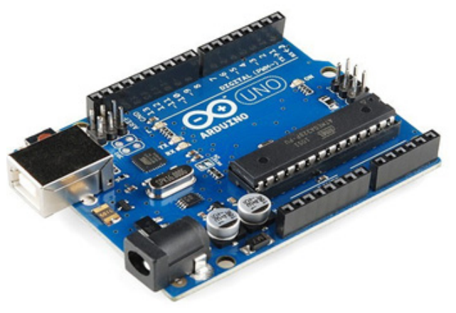
Figure 2.
Solderless breadboard used for electronic circuit prototyping [34].
Figure 2.
Solderless breadboard used for electronic circuit prototyping [34].
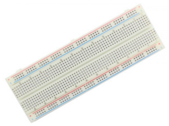
Figure 3.
Infrared (IR) sensor [30].
Figure 3.
Infrared (IR) sensor [30].
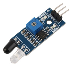
Figure 4.
Emission and reflection of infrared radiation by an IR sensor [20].
Figure 4.
Emission and reflection of infrared radiation by an IR sensor [20].
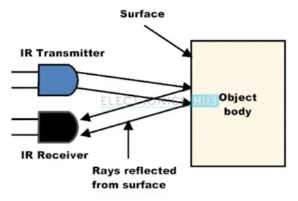
Figure 5.
Conceptual model of a vehicle passing two IR sensors positioned alongside the roadway.
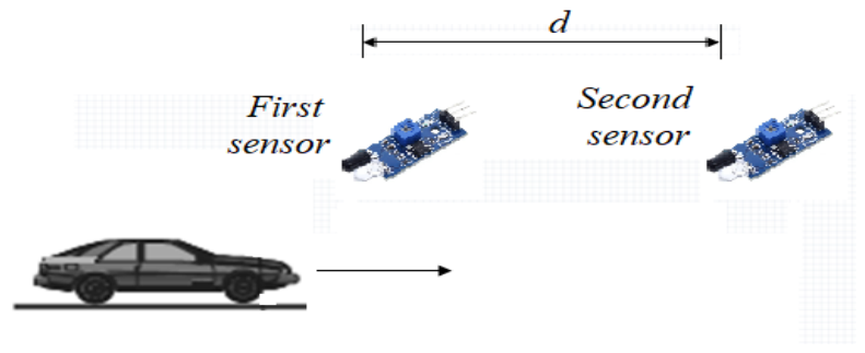
Figure 6.
16 × 2 LCD display module [28].
Figure 6.
16 × 2 LCD display module [28].
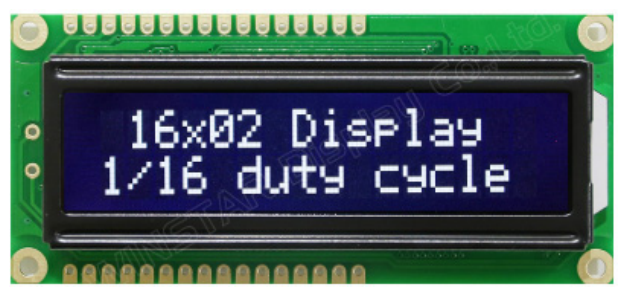
Figure 7.
Electronic buzzer [39].
Figure 7.
Electronic buzzer [39].
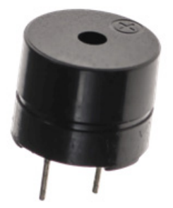
Figure 8.
Light-emitting diode (LED) [27].
Figure 8.
Light-emitting diode (LED) [27].
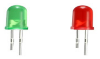
Figure 9.
Electronic resistors [35].
Figure 9.
Electronic resistors [35].
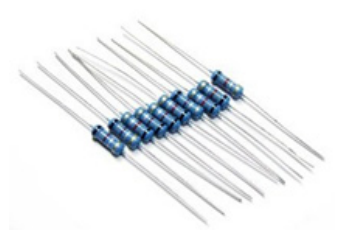
Figure 10.
Types of jumper wires [35].
Figure 10.
Types of jumper wires [35].
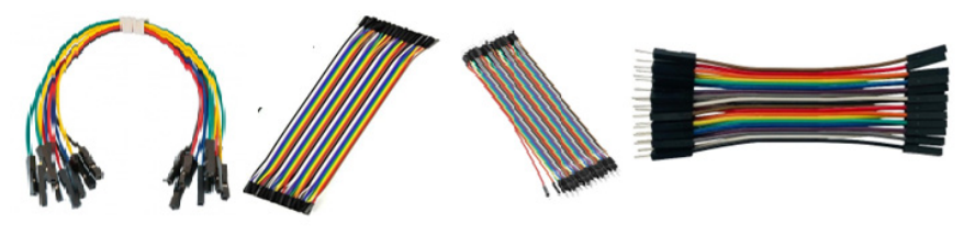
Disclaimer/Publisher’s Note: The statements, opinions and data contained in all publications are solely those of the individual author(s) and contributor(s) and not of MDPI and/or the editor(s). MDPI and/or the editor(s) disclaim responsibility for any injury to people or property resulting from any ideas, methods, instructions or products referred to in the content. |
© 2026 by the authors. Licensee MDPI, Basel, Switzerland. This article is an open access article distributed under the terms and conditions of the Creative Commons Attribution (CC BY) license.
Copyright: This open access article is published under a Creative Commons CC BY 4.0 license, which permit the free download, distribution, and reuse, provided that the author and preprint are cited in any reuse.