

Submitted:
23 October 2026
Posted:
27 October 2026
You are already at the latest version
Abstract
The rapid growth of large electricity-consuming facilities, including hyperscale data centers, hydrogen electrolyzers, cryptocurrency mining operations, electric vehicle charging hubs, and electrified industrial processes, is introducing new challenges for transmission planning and power system reliability. Unlike traditional aggregated loads, many emerging large loads are highly concentrated, exhibit rapid power variations, and increasingly rely on power-electronic interfaces, resulting in dynamic behaviors that are not adequately represented by conventional load models. Consequently, accurate load modeling has become essential for steady-state analysis, stability assessment, interconnection studies, and long-term transmission planning. This paper presents a comprehensive review of large load modeling methodologies and their applications in future transmission planning. The evolution of load modeling is examined from classical static ZIP models and induction motor representations to composite load models and emerging power-electronic load models such as LDEV1 and PERC1. Measurement-based and component-based modeling approaches are reviewed along with their advantages, limitations, and validation requirements. The paper further discusses the role of large load models in power flow studies, voltage and transient stability assessments, electromagnetic transient simulations, and planning under uncertainty. Current utility practices, industry initiatives, and evolving interconnection requirements are also summarized. Finally, key challenges are identified, including model validation, data availability, platform inconsistencies, and the representation of converter-dominated loads. The review highlights the need for standardized modeling frameworks, improved measurement-based validation, and enhanced collaboration among utilities, researchers, and regulators to support the reliable integration of large loads into future power systems.
Keywords:
composite load models
; data center loads
; large load modeling
; power system stability
; transmission planning
1. Introduction
The unprecedented rise of large electrical loads in modern power systems has profound implications for grid planning and reliability. Large loads — broadly defined as any single site or aggregated facility demanding tens to hundreds of megawatts that can pose bulk power system reliability risks — are proliferating rapidly across many regions [1]. Prominent examples include hyperscale data centers, large-scale electric vehicle fast-charging depots, hydrogen production via electrolysis, cryptocurrency mining farms, and other industrial facilities dominated by power-electronic interfaces. Many of these loads have consumption profiles comparable to a mid-sized city, yet are concentrated at a single interconnection point. They also exhibit unique operational characteristics: their power-electronics-based equipment can modulate or curtail power almost instantaneously during grid events, a trait that introduces reliability risks distinct from those posed by traditional load growth [2].
These characteristics, combined with accelerating deployment, have made large loads a top reliability concern. U.S. data centers consumed approximately 4.4% of national electricity in 2023 and, according to the Lawrence Berkeley National Laboratory (LBNL), are projected to reach between 6.7% and 12.0% of national electricity consumption by 2028 [3]. The Electric Power Research Institute (EPRI) similarly estimates data center consumption could reach up to 9% of U.S. generation by 2030 [4]. The Western Electricity Coordinating Council (WECC) projects annual energy demand in the Western Interconnection to grow by more than 20% over the next decade (more than double the rate forecast just two years prior) driven in large part by data centers, manufacturing facilities, and cryptocurrency mining [5,6]. These growth rates have not been observed since the 1950s.
Similar trends are emerging across Europe, where rapid electrification, large-scale hydrogen-production projects, and hyperscale data-center development are creating new challenges for transmission-system planning. In Ireland, data centers accounted for approximately 22% of national electricity consumption in 2024, prompting EirGrid and the Commission for Regulation of Utilities (CRU) [7] to introduce dedicated connection policies and planning requirements for large electricity users. More broadly, European transmission system operators are increasingly considering the impacts of large flexible loads, including data centers and hydrogen electrolyzers, within long-term transmission-expansion and decarbonization planning frameworks. These developments indicate that the reliable integration of large electricity-consuming facilities has become a global transmission-planning challenge rather than an issue confined to North America [8,9].
In response, the North American Electric Reliability Corporation (NERC) established the Large Loads Task Force (LLTF) in October 2024 to identify the unique technical and operating characteristics of these loads and develop reliability solutions [10,11], while WECC released a comprehensive report in February 2025 detailing interconnection risks across the Western Interconnection [5].
Accurate load modeling and analysis are therefore essential for transmission planning in the evolving grid environment. The integration of large loads can significantly influence all aspects of system planning and reliability assessments. From a steady-state perspective, the substantial demand associated with these resources may create localized congestion, increase power transfer requirements, and necessitate significant transmission reinforcements to maintain acceptable thermal loadings and voltage performance. In electrically weak or remote areas, the addition of large constant-power loads may further reduce voltage stability margins, potentially driving system operating conditions closer to the voltage collapse point during periods of peak demand.
The implications for dynamic and transient performance are equally significant. Many large electronically interfaced loads exhibit heightened sensitivity to short-duration voltage and frequency disturbances and may respond to system events through rapid load reduction or complete disconnection. Uncoordinated load tripping of this magnitude can introduce substantial system disturbances, including overvoltage conditions, frequency excursions, and altered power flow patterns, potentially resulting in the operation of protective devices and adversely affecting generator stability. The bulk power system impacts of such behavior are often difficult to predict using conventional load modeling assumptions.
A notable example occurred in July 2024, when a fault on a 230-kV transmission line triggered customer protection systems that disconnected approximately 1,500 MW of data center load distributed across roughly 60 interconnection points [12]. The scale and speed of the resulting load loss were not anticipated by bulk system operators, highlighting the growing importance of accurately characterizing large-load behavior and protection system responses in transmission planning, operational studies, and reliability assessments. Conversely, the rapid restoration or reconnection of large loads following a disturbance can introduce additional challenges to system stability. Abrupt load recovery may increase post-fault system stress, exacerbate transient stability limitations, and contribute to poorly damped electromechanical oscillations. Protection and fault studies must likewise be re-examined in the presence of converter dominated loads. Unlike conventional induction motor loads, these facilities often exhibit limited short circuit current contributions, fast control actions, and atypical fault response characteristics. As a result, existing protection schemes, relay settings, and interconnection requirements may require modification to ensure reliable fault detection, system protection, and overall grid security.
Despite the growing significance of these issues, a substantial gap remains between prevailing industry practice and the modeling fidelity required to accurately assess emerging large-load facilities. Traditional utility planning studies frequently rely on simplified load representations, including aggregated ZIP (constant impedance, constant current, and constant power) models or static load assumptions, which are often inadequate for capturing the dynamic behavior of modern power-electronic loads. Critical characteristics including voltage and frequency ride-through capabilities, control system dynamics, recovery behavior following disturbances, and interactions with other inverter based resources are frequently absent from current planning models. The omission of these features can lead to an underestimation of both local and system-wide reliability impacts, particularly under stressed operating conditions.
As the scale and prevalence of data centers, large-scale electrification projects, cryptocurrency mining facilities, and other electronically interfaced loads continue to increase, the limitations of conventional modeling approaches become increasingly pronounced. Recognizing this challenge, both the research community and industry organizations have emphasized the need for higher-fidelity load representations, including composite and user-defined dynamic models that explicitly capture control architectures, protection responses, and disturbance-driven behavior. Such models are expected to play a critical role in ensuring the accuracy of future transmission planning, interconnection studies, operational assessments, and bulk power system reliability evaluations. For example, the Electric Reliability Council of Texas (ERCOT) has introduced enhanced requirements mandating that interconnecting large loads provide detailed dynamic and electromagnetic transient (EMT) models, in PSSE and PSCAD respectively, and submit validated model data at multiple checkpoints throughout the interconnection lifecycle [13,14]. Likewise, NERC reliability standard MOD-032 obligates data owners to share steady-state, dynamic, and short-circuit modeling data with planning coordinators and transmission planners on an interconnection-wide basis [15]. These developments illustrate an urgent and ongoing shift in industry practice toward more sophisticated load modeling, bridging the current gap and ensuring that planners can rely on their simulations to maintain system reliability as large loads become a large portion of aggregate demand.
The remainder of this paper is organized as follows. Section 2 reviews the definition, taxonomy, and modeling methodologies of large loads. Section 3 discusses their applications in transmission planning studies. Section 4 presents an illustrative data center case study. Section 5 summarizes industry practices and utility approaches. Section 6 discusses challenges and future research directions. Finally, Section 7 concludes the paper.
2. Definition and Taxonomy of Large Loads
The term large load lacks a universally adopted definition in power systems literature, and its interpretation varies significantly across regulatory authorities, Regional Transmission Organizations (RTOs), utilities, and academic studies. This definitional ambiguity is not merely a semantic concern: the absence of standardized criteria creates inconsistency in interconnection study requirements, load forecasting obligations, planning data collection, and reliability standard applicability, all of which have direct consequences for bulk power system reliability [1,16].
2.1. The Challenge of a Universal Definition
At the most fundamental level, a large load can be understood as any electricity customer whose peak demand is sufficiently large to impose measurable operational costs on the grid and/or to trigger system-wide stability and reliability risks that require upfront assessment and resolution, often involving joint action between the grid operator and the load customer [16]. However, translating this functional description into a precise, universally applicable numerical threshold has proved difficult, because the impact of a given load depends not only on its magnitude but also on the characteristics of the local network to which it connects. As NERC’s LLTF concluded in its July 2025 white paper, peak demand is only one of many characteristics that can affect bulk power system reliability, and any definition based solely on a single MW threshold may be overly simplistic [1].
Despite this inherent complexity, regulatory bodies and system operators have historically defined large loads primarily through power thresholds, which vary considerably across jurisdictions. ERCOT designates loads of 75 MW or greater as large for standalone facilities, and 20 MW or greater for loads co-located with a generation resource [1]. The New York Independent System Operator (NYISO) requires interconnection studies for loads of 10 MW or greater connecting at 115 kV or above, and for loads of 80 MW or greater connecting below 115 kV [1]. Dominion Energy, whose service territory encompasses the world’s largest concentration of data centers, applies a threshold of 100 MW for transmission-level load interconnections [1]. Similarly, Xcel Energy applies its large-load technical requirements and proposed large-load tariff framework to new transmission-connected facilities with demand of 50 MW or greater, while reserving the right to evaluate smaller loads that may present material reliability impacts [17]. An informal survey conducted by the NERC LLTF in November 2024 found that most respondents qualified “large” as greater than 50 MW, with 75 MW being the single value most frequently suggested [1]. At the federal level, the Federal Energy Regulatory Commission (FERC), responding to a directive from the U.S. Secretary of Energy in October 2025, initiated an Advance Notice of Proposed Rulemaking (ANOPR) proposing reforms to the interconnection of large loads generally defined as demand exceeding 20 MW [18,19]. Table 1 summarizes the key institutional thresholds and definitions.
These varying thresholds reflect important differences in network topology, system inertia, and regional planning practices. In the Eastern Interconnection, for example, the large total inertia and abundant generation capacity mean that a 50 MW load loss produces a much smaller frequency excursion than the same event would in the ERCOT interconnection, which has lower system inertia and greater exposure to sudden imbalances [1]. Accordingly, defining a load as “large” cannot be reduced to a single number universally applied across all interconnections.
2.1.1. The NERC LLTF Functional Definition
The most authoritative and broadly applicable definition currently in use in North America is that established by the NERC LLTF, which was formed in August 2024 specifically to address the reliability implications of emerging large loads. For the purposes of its white paper series and associated reliability guideline, the LLTF defines a large load as follows [1]:
“Any commercial or industrial individual load facility or aggregation of load facilities at a single site behind one or more point(s) of interconnection that can pose reliability risks to the bulk power system due to its demand, operational characteristics, or other factors. Examples include, but are not limited to, data centers, cryptocurrency mining facilities, hydrogen electrolyzers, manufacturing facilities, and arc furnaces.”
This definition was subsequently adopted in NERC’s September 2025 level 2 industry recommendation on large load interconnection, study, commissioning, and operations [20], and is expected to be incorporated into the NERC glossary of terms used in reliability standards in a modified form in future revisions [1]. Several features of this definition merit careful attention.
First, it is intentionally technology- and sector-agnostic: the definition does not restrict the concept of “large load” to any particular end-use category, recognizing that the relevant characteristic is the nature of the load’s interaction with the bulk power system rather than the industry it serves.
Second, it is multi-attribute and qualitative: the phrase “due to its demand, operational characteristics, or other factors” explicitly acknowledges that bulk power system reliability risks can arise from properties other than peak power magnitude. These include but are not limited to ramp rates, ride-through behavior, reactive power characteristics, harmonic injection, and behind-the-meter generation configurations. This reflects the LLTF’s finding that many emerging large loads exhibit behaviors (particularly rapid power fluctuations driven by power electronics and algorithmic control) that were not characteristic of the large industrial loads for which existing reliability standards were originally developed [1].
Third, the definition does not specify a MW threshold, a deliberate choice that acknowledges the context-dependence of what constitutes a “large” impact. As the LLTF noted, a 20 MW load would be considered large on a distribution feeder but relatively small if interconnected at transmission voltage levels; what matters is the potential for reliability impact on the bulk power system rather than the absolute magnitude of the demand [1].
2.1.2. Multi-Attribute Characterization Framework
Given the limitations of threshold-only definitions, the power systems research community and the Idaho National Laboratory (INL) have advanced a multi-attribute characterization framework that identifies three fundamental characteristics through which large loads can be distinguished and classified from a grid operator’s perspective [16].
i. Load size
refers to the maximum instantaneous power that a load may draw at any point in time. INL’s taxonomy report, prepared for the U.S. Department of Energy’s Grid Deployment Office, proposes three size tiers: 50–99 MW (entry-level large load), 100–999 MW (major industrial or hyperscale), and ≥1,000 MW (transformative, generation-scale). At 100 MW, loads begin to trigger more rigorous transmission planning and reliability assessments due to their potential to influence regional power flows and system stability, while loads exceeding 1,000 MW rival utility-scale generation in their grid impact and often require custom infrastructure and policy-level coordination [16].
ii. Load variability
refers to the degree and speed with which a load’s power consumption changes under normal operating conditions. Loads are classified as having a slow load profile (consistent and predictable demand, with significant power swings (defined as ≥50 MW) occurring rarely and over intervals longer than 60 minutes) or a fast load profile (significant power swings occurring frequently and within short intervals as a direct consequence of the facility’s operations) [16]. The importance of load variability has been dramatically illustrated by observed field events: for example, an AI training data center was documented ramping a 50 MW block of its 200 MW capacity at a rate of 1.9 pu/s for approximately 250 milliseconds during training-to-checkpoint transitions [1], and a cryptocurrency mining facility was observed ramping down 298 MW within 25 seconds following a control system disturbance [1]. These rates far exceed the ramping capabilities of conventional thermal generation, creating reserve adequacy and frequency regulation challenges.
iii. Load flexibility
refers to the degree to which a load can alter its power consumption from the grid in response to requests from the grid operator without adversely affecting its essential operational and business functions [16]. A flexible load can raise or lower its net power consumption to provide ancillary services; an inflexible load cannot do so due to technical constraints (lack of behind-the-meter storage or generation), mission criticality, or organizational policy. Load flexibility is also modulated by behind-the-meter resources: on-site generation and storage enable a facility to partially or fully decouple from the grid on short notice, increasing its effective flexibility from the grid operator’s perspective, even if the facility’s internal process load is physically inflexible [16].
Together, these three characteristics, namely size, variability, and flexibility, form an orthogonal basis for classifying large loads in a way that is directly relevant to planning and operational decision-making, independent of the specific technology or industry sector involved.
2.1.3. Distinction from Conventional and Distribution-Level Loads
A large load, as defined above, differs from conventional load representations used in transmission planning in several qualitatively important respects beyond sheer magnitude.
i. Point of interconnection and modeling granularity
Conventional transmission planning treats the load attached to each transmission bus as an aggregate of thousands of individual consumers served through the distribution system, whose collective behavior can be statistically characterized. A large load, by contrast, is a single facility or campus directly interconnected at the subtransmission or transmission voltage level, and its individual behavior cannot be averaged away. A single large load may represent 5–30% of the peak demand on a local transmission element, and its addition, loss, or behavioral change will produce a deterministic shift in system conditions [1].
ii. Dynamic behavior and power electronics penetration
Traditional aggregate transmission loads are predominantly composed of induction motors, resistive heating, and lighting, whose voltage- and frequency-dependent behavior is well characterized and has been extensively incorporated into industry-standard composite load models. Emerging large loads are predominantly composed of power-electronic-interfaced equipment: uninterruptible power supplies, variable-speed drives, server power supplies, rectifiers, and inverters. These devices exhibit fundamentally different dynamic behavior, including the ability to ramp power consumption at rates of hundreds of MW per second, to disconnect from the grid in response to transient voltage disturbances (rather than riding through them as induction motors do), and to produce leading power factors and harmonic currents that aggregate load models do not capture [1].
iii. Reliability risks already observed in the field
The distinction between large loads and conventional loads is not merely theoretical. Both the Eastern Interconnection and ERCOT have observed simultaneous voltage-sensitive load reductions exceeding 1,500 MW each, triggered by transmission faults, in which large loads (primarily data centers and other power-electronic loads) disconnected or transferred to backup generation—events not anticipated by existing power system models [1]. NERC observed more than 1,000 MW of unexpected large load reductions across multiple events in 2024 and 2025 [20]. These events have demonstrated that the aggregate behavior of large loads during system disturbances can materially alter bulk power system frequency, voltage, and angular stability in ways that require explicit modeling and proactive interconnection planning.
2.1.4. Working Definition Adopted in This Paper
Drawing on the regulatory, institutional, and technical frameworks reviewed above, this paper adopts the following composite working definition:
A large load is any commercial or industrial facility, or aggregation of facilities at a single site, that satisfies one or more of the following criteria: (i) it has a peak power demand of 20 MW or greater on the interstate transmission system, consistent with the threshold adopted in the FERC ANOPR [18]; (ii) it directly interconnects at the subtransmission (69 kV and above) or transmission voltage level; or (iii) regardless of absolute magnitude, it exhibits dynamic or operational characteristics, including high ramp rates, voltage-sensitive disconnection behavior, significant harmonic injection, or rapid load cycling, that are sufficiently distinct from the aggregate distribution-served load to require individualized representation in transmission planning studies [1,16].
This definition intentionally encompasses both long-established heavy industrial loads (aluminum smelters, electric arc furnaces, chemical facilities) and the rapidly expanding class of digitally intensive and electrochemical loads (hyperscale data centers, AI training facilities, cryptocurrency mining operations, and hydrogen electrolyzers). It also accommodates behind-the-meter configurations, in which a large load is served partly or fully by co-located generation, a configuration whose reliability implications are distinct from a purely front-of-meter load and whose treatment in interconnection procedures remains an active area of regulatory development [18,19].
2.1.5. European Regulatory Perspective on Large Loads
European regulatory frameworks generally classify demand facilities according to their system impact, voltage level of connection, and operational characteristics rather than a single power threshold. The principal regulatory framework governing transmission-connected demand facilities within the European Union is the Demand Connection Code (DCC), formally adopted under commission regulation (EU) 2016/1388 [21,22]. The DCC establishes harmonized technical requirements for demand facilities, distribution systems, and demand-side resources providing demand response services. Rather than focusing exclusively on peak demand magnitude, the framework emphasizes voltage and frequency ride-through capability, reactive power performance, disturbance resilience, and system-support functionalities. Consequently, facilities with large and dynamic power consumption, including hyperscale data centers, hydrogen electrolyzers, and electrified industrial installations, may be subject to detailed technical requirements regardless of whether they exceed a predefined MW threshold. This approach reflects a broader European planning philosophy in which large loads are increasingly viewed as active participants in system operation rather than passive consumers. As a result, system operators frequently evaluate not only the magnitude of demand but also the flexibility, controllability, and ancillary-service capabilities of large customer facilities. Such considerations are expected to become increasingly important as Europe continues its transition toward a power system characterized by large shares of inverter-based renewable generation and electrified industrial demand [23].
2.2. Load Modeling Approaches: Measurement-Based and Component-Based Methods
Load modeling plays a critical role in power system analysis, particularly in transmission planning studies involving stability, reliability, and interconnection assessments. From the perspective of parameter identification and model construction, load modeling methodologies can be broadly categorized into two primary approaches: measurement-based and component-based approaches. These approaches define how model parameters are obtained and calibrated, and they are largely independent of the specific mathematical structure of the load model (e.g., static, dynamic, or composite models) [24].
2.2.1. Measurement-Based Approach
The measurement-based approach relies on field measurements to infer load model parameters. High-resolution data obtained from phasor measurement units, as well as supervisory control and data acquisition systems, are commonly used to capture the dynamic response of loads under various operating conditions and disturbances [25]. The core principle of this approach is to estimate model parameters such that the simulated load response closely matches the observed behavior in the measured data.
In this approach, system identification techniques, optimization methods, and statistical regression are often employed to calibrate load models. Parameter estimation algorithms, including least squares methods, genetic algorithms, and particle swarm optimization, have been applied to fit model responses to recorded disturbance events [26,27]. By leveraging real disturbance events, such as voltage sags or frequency excursions, measurement-based methods can capture aggregated load dynamics and nonlinear behaviors that are otherwise difficult to model explicitly. As highlighted in the literature, this approach is particularly effective in representing modern loads with complex control systems and power electronic interfaces, where internal structure and proprietary details may not be readily available [26,28].
However, the measurement-based approach is limited by the availability and quality of measurement data. Its applicability may be constrained in planning studies for future systems or new large load interconnections where historical data does not exist. Furthermore, the accuracy of the identified models can be sensitive to measurement noise and the diversity of operating conditions captured in the dataset [25].
2.2.2. Component-Based Approach
In contrast, the component-based approach constructs load models by explicitly representing the physical composition and characteristics of individual load components. In this framework, the total load is modeled as an aggregation of constituent elements such as induction motors, static loads, power electronic devices, and other end-use components. Each component is represented using physics-based or empirical models derived from engineering knowledge, manufacturer specifications, or standard model libraries [24,29].
This approach provides a transparent and interpretable representation of load behavior, enabling engineers to analyze the impact of specific components on system dynamics. It is widely used in composite load modeling frameworks, where different categories of loads (e.g., motor types, electronic loads, and static loads) are combined to form a detailed aggregate representation. Component-based modeling is particularly valuable for studying new large loads, such as data centers and industrial facilities, where engineering design information is available prior to commissioning.
Despite its advantages, the component-based approach requires detailed knowledge of load composition, which may be difficult to obtain in practice. Moreover, simplifying assumptions about component behavior and aggregation can lead to inaccuracies, especially for emerging loads dominated by power electronics and advanced controls [30].
2.2.3. Hybrid and Integrated Methodologies
Both measurement-based and component-based approaches offer complementary advantages. The measurement-based approach excels in capturing real system behavior, while the component-based approach provides interpretability and predictive capability for new system configurations. Recognizing these strengths and limitations, recent research and industry guidelines advocate for hybrid methodologies that integrate both approaches to improve model accuracy and robustness [28].
In hybrid frameworks, component-based model structures are retained to preserve physical interpretability, while measured field data are used to tune or validate model parameters. This integration allows planners to leverage available measurements for calibration while maintaining the ability to adapt models for future load configurations where measurements may not yet exist [26]. Such approaches are recommended by reliability organizations, including NERC, as part of best practices for load modeling in bulk power system planning studies [30].
2.3. Evolution of Load Modeling Philosophy: From Static ZIP Models to Composite Dynamic Models
The philosophy of load modeling in power systems has undergone substantial transformation over the past decades, driven by the increasing penetration of motor-dominated and inverter-based loads, widespread deployment of distributed energy resources, and the emergence of fault-induced delayed voltage recovery (FIDVR) as a critical planning concern [26,28,31]. Early approaches relied on static ZIP models which, while computationally tractable, failed to capture the transient motor stall dynamics and protection-driven load loss observed during severe voltage disturbances [32,33]. This inadequacy, made evident by events such as the 2011 Southwest blackout and repeated FIDVR incidents across the Western Interconnection, catalyzed the shift toward component-based composite load models capable of disaggregating feeder-level behavior into motor classes, electronic loads, and distributed generation, each governed by its own dynamic response characteristic [26,32]. Figure 1 summarizes the progression of load modeling methodologies over the past several decades. As the electrical characteristics of end-use loads evolved from predominantly static and electromechanical devices to converter-interfaced and digitally controlled resources, load models similarly advanced from ZIP formulations and induction motor representations to composite load models, power-electronics-based models, and emerging large digital load frameworks such as PERC1 and LDEV1 that are designed to capture the aggregate behavior of modern AI data centers and other flexible large loads.
2.3.1. Static Load Modeling and the ZIP Paradigm
Static load models represent the aggregate electrical behavior of loads as algebraic functions of bus voltage and, in some cases, frequency, evaluated at the same instant of time. Such models are widely used in steady-state and quasi-steady-state analyses due to their simplicity and computational efficiency [34].
Within this category, the most commonly adopted representation is the polynomial load model, often referred to as the ZIP model. In this formulation, the load is expressed as a weighted combination of constant impedance (Z), constant current (I), and constant power (P) components [34]. These individual components correspond to distinct physical behaviors: constant impedance loads exhibit a quadratic dependence on voltage magnitude, constant current loads vary linearly with voltage, and constant power loads remain invariant under voltage variations within a certain operating range [34].
Accordingly, the active and reactive power consumption of a load can be expressed in normalized form as:
where are the model coefficients and a key modeling constraint is that these coefficients must satisfy the normalization condition:
which ensures that the model reproduces the nominal load power at the reference operating point (). , , and denote nominal operating conditions. This polynomial formulation provides a flexible framework to approximate the aggregated behavior of heterogeneous load compositions [34].
Historically, the ZIP representation emerged as a practical means of capturing voltage-dependent load characteristics in power system studies, and its widespread adoption has been attributed to its ability to approximate a mixture of load components using a small set of parameters [35]. Early formulations introduced the decomposition of loads into these three canonical components, enabling analytical tractability in power flow and stability studies.
Despite its simplicity, the ZIP model has been shown to capture key steady-state characteristics of aggregate system loads with reasonable accuracy. Experimental validation by Bokhari et al. [35] confirmed that ZIP coefficients vary significantly across residential, commercial, and industrial classes, underscoring that accurate representation requires load-class-specific calibration rather than universal parameter sets. These studies further highlight that the coefficients of the model depend strongly on load composition and must be calibrated using measurements or representative component data.
Nevertheless, the validity of static load models is inherently limited to conditions where load dynamics are negligible. While they are suitable for representing resistive loads and approximating certain aggregate behaviors, they fail to capture time-dependent phenomena associated with dynamic components such as induction motors, electronic loads, and control-driven devices [34]. In particular, static models assume an instantaneous adjustment of power with voltage changes, neglecting delays, recovery dynamics, and discontinuities observed in real systems.
As a result, although ZIP models remain an essential tool for steady-state and planning studies, their limitations have motivated the development of more advanced representations, particularly for applications involving large disturbances, voltage stability assessment, and dynamic performance analysis.
2.3.2. Transition to Dynamic and Hybrid Load Models: Induction Motor (IM) and ZIP+IM Representations
While static load models such as the ZIP formulation provide a convenient algebraic characterization of load behavior under steady-state conditions, they are inherently incapable of capturing the time-dependent dynamics exhibited by modern power system loads. As highlighted in IEEE Std 2781, dynamic load models are required to describe the temporal evolution of load response following disturbances, particularly when loads exhibit multiple-stage responses influenced by electromechanical interactions and control mechanisms [28].
Induction Motor (IM) Load Models:
Among dynamic load representations, IM models constitute the most fundamental and widely adopted approach for capturing load dynamics [36]. This prominence stems from the fact that a significant portion of aggregate power system loads, particularly in industrial and commercial sectors, are motor-driven, including compressors, pumps, and heating, ventilation, and air conditioning (HVAC) systems [28].
Dynamic IM models describe the load behavior using a set of nonlinear differential equations that represent the electromechanical interactions between the stator, rotor, and the connected mechanical load. A general representation can be expressed in state-space form as:
where x denotes the internal state variables (e.g., rotor flux, slip), and V is the terminal voltage. The dynamic nature of this formulation enables the model to capture critical transient phenomena such as rotor acceleration/deceleration, motor stalling, and delayed voltage recovery.
Higher-order IM models, such as third-order or fifth-order representations, are commonly employed depending on the required level of accuracy [28]. These models explicitly account for subtransient and transient dynamics, making them essential for transient stability and voltage stability studies. In particular, motor stalling behavior under severe voltage depression can significantly impact system recovery and may lead to voltage collapse if not properly represented.
Despite their physical accuracy, IM models alone are insufficient to represent the full spectrum of load characteristics, as not all components of the aggregate load exhibit dynamic electromechanical behavior. This limitation motivates the development of hybrid modeling approaches.
ZIP + IM Hybrid Models:
To improve modeling fidelity while maintaining computational tractability, hybrid models combining static and dynamic components have been widely adopted [37,38]. The most common formulation is the ZIP+IM model, where the aggregate load is decomposed into a voltage-dependent static part and a dynamic motor-driven component.
In this framework, the total load is expressed as:
where the ZIP component captures the instantaneous voltage-dependent response, and the IM component represents the dynamic behavior of motor loads.
This hybrid structure aligns with the classification of load models described in IEEE Std 2781, where static models provide algebraic relationships and , while dynamic models introduce differential relationships to capture time-dependent effects [28]. By combining these two representations, the ZIP+IM model enables a more realistic approximation of aggregate load dynamics under both steady-state and disturbed conditions.
In practical applications, this approach has been widely adopted by utilities, where the majority of load dynamics are represented through IM models combined with ZIP or exponential static load models [39]. The resulting structure provides a significant improvement over purely static models, particularly in capturing phenomena such as FIDVR and oscillatory behavior following disturbances.
However, the ZIP+IM formulation remains limited in its ability to accurately represent the diverse and nonlinear characteristics of modern loads. As noted in recent studies, such simplified combinations may fail to capture interactions between different load components and can mischaracterize the aggregated dynamic response, especially in systems with high penetration of power electronic devices and heterogeneous load compositions [39,40].
These limitations ultimately motivated the development of more advanced composite load models, such as the WECC composite model and the complex load model, which extend the hybrid framework by explicitly incorporating multiple load components with distinct physical behaviors.
2.3.3. Complex Load Model (CLOD) Framework
Composite load modeling approaches have been developed by combining static and dynamic components into a unified framework. In such models, the aggregate load is represented as a combination of voltage-dependent static elements and dynamic components, most notably induction motors and electronically controlled loads [28]. This hybrid representation enables the model to capture both steady-state characteristics and transient dynamics of modern power system loads.
A widely adopted implementation of this philosophy in industry applications is the Complex Load (CLOD) model, which is available in commercial simulation platforms such as PSSE and PowerWorld [39,41]. The overall structure of the CLOD model is illustrated in Figure 2, where the total load at a bus is represented as an aggregation of several physically meaningful submodels, including:
- large and small induction motor loads,
- discharge lighting loads,
- transformer saturation effects,
- constant MVA (constant power) loads, and
- a remaining static load component.
Each of these submodels contributes to the overall active and reactive power demand, resulting in an aggregate representation:
where each component i corresponds to a specific physical load type within the composite structure.
A key feature of the CLOD model is its ability to capture dynamic behavior through the inclusion of induction motor models, typically represented using higher-order differential equations. For example, both large and small motor loads are modeled using induction machine formulations capable of representing subtransient and transient dynamics, including rotor slip and electromagnetic interactions [39,41]. This enables accurate representation of phenomena such as motor stalling, delayed voltage recovery, and oscillatory behavior following disturbances.
In addition to motor dynamics, the model incorporates nonlinear and voltage-dependent behavior of other load components. For instance, discharge lighting loads are represented using piecewise voltage-dependent functions, while transformer saturation effects are captured through nonlinear relationships that primarily impact reactive power consumption [39]. Constant power loads are modeled to maintain fixed power consumption under normal conditions but transition to voltage-dependent behavior under severe voltage deviations.
Compared to simpler approaches such as the combination of ZIP and IM models, composite models like CLOD provide improved accuracy in representing aggregated load behavior. Traditional ZIP+IM formulations may fail to fully capture the interactions between different load components and can mischaracterize dynamic responses under disturbances [39,42]. Although more detailed models such as the WECC composite load model offer high fidelity, their complexity introduces challenges related to parameter identification, convergence, and computational burden [39,43].
The CLOD model addresses these challenges by offering a reduced-order yet physically meaningful representation, requiring a relatively small number of parameters while maintaining sufficient accuracy for large-scale power system simulations [39]. This balance between fidelity and computational efficiency makes it especially suitable for transmission-level studies and industrial applications where scalability is essential [39,44]. However, because the CLOD model does not explicitly represent motor flux dynamics, it may not accurately capture certain voltage stability phenomena, particularly wide-area short-term voltage collapse under severely depressed voltage conditions. Consequently, higher-fidelity models may be required when studying such events.
Nevertheless, the effectiveness of composite load modeling relies heavily on accurate parameter estimation and proper characterization of load composition [45]. As highlighted in IEEE Std 2781, the development of such models increasingly depends on hybrid methodologies that combine component-based knowledge with measurement-based data to reflect the evolving nature of modern loads [28].
Therefore, composite models such as CLOD represent a critical step in the evolution of load modeling, bridging the gap between simple static representations and fully detailed dynamic models, and enabling more realistic simulation of power system behavior under both steady-state and transient conditions.
2.3.4. Composite Load Model (CMLD) Framework
Building upon the CLOD framework, composite load modeling has evolved into a more comprehensive representation of aggregate load behavior in modern power systems. While CLOD successfully integrates static load characteristics with IM dynamics and has been widely adopted in commercial stability analysis tools, increasing load diversity, growing penetration of electronic loads, and the need to accurately reproduce voltage recovery phenomena have exposed limitations in earlier composite formulations [25,46]. These challenges motivated the development of Composite Load Models (CMLDs), which incorporate multiple dynamic load categories, distribution system representations, protection mechanisms, and inverter-based resources within a unified modeling framework [46,47]. CMLDs therefore represent the current state-of-the-art approach for aggregate load representation in transmission planning and dynamic security assessment studies [25,47,48].
Unlike earlier ZIP+IM and CLOD formulations that describe aggregate load dynamics using a single IM equivalent, modern CMLDs explicitly preserve the diversity of end-use load components. The underlying philosophy is that practical power system loads consist of a mixture of static devices, motor-driven equipment, power-electronic loads, and distributed energy resources, each exhibiting distinct electrical characteristics during disturbances [46,47]. Consequently, modern composite load models are constructed from multiple sub-models connected in parallel, allowing residential, commercial, and industrial load classes to be represented according to their specific dynamic behaviors [46].
The evolution toward CMLDs was strongly influenced by industry experience with major voltage stability events, particularly those involving FIDVR. Studies demonstrated that conventional static and simplified composite load models often failed to reproduce the delayed voltage recovery observed following transmission faults [25,47]. Detailed investigations revealed that stalled induction motors, particularly residential air-conditioning compressors, played a dominant role in these events [46,47]. As a result, WECC initiated the development of an advanced composite load model capable of explicitly representing the electrical distance between transmission substations and end-use devices while incorporating detailed motor dynamics and protection mechanisms [25,47].
The resulting WECC composite load model has become the most widely adopted implementation of the modern CMLD philosophy [25,46]. The model consists of an equivalent distribution transformer, feeder impedance, shunt compensation devices, static loads, multiple categories of three-phase induction motors, single-phase air-conditioner motors, electronic loads, and, in more recent versions, distributed energy resource models [47,48]. By explicitly representing the distribution system between the transmission bus and aggregated end-use devices, the model captures voltage drops across feeders and reproduces motor stalling behavior with significantly greater accuracy than previous aggregate load representations [47].
A distinguishing feature of the WECC CMLD is the use of multiple motor categories to represent different classes of end-use equipment. Motor A is typically used to represent low-inertia constant-torque loads such as air-conditioning compressors, Motor B represents high-inertia variable-torque loads such as ventilation and fan systems, and Motor C models low-inertia variable-torque loads such as centrifugal pumps [46,48]. Additionally, a performance-based air conditioner model is used to capture the dynamic behavior of residential air-conditioning units, which are widely recognized as a major contributor to FIDVR events [46,47]. This level of motor classification allows the composite model to reproduce both electromechanical and voltage recovery dynamics more accurately than earlier aggregate representations [46,48].
The incorporation of single-phase residential air-conditioner motors represents one of the most significant advancements in modern composite load modeling. Extensive laboratory testing and field-event analysis demonstrated that compressor motors exhibit unique stalling and recovery characteristics that cannot be adequately captured using conventional IM equivalents [25,46]. Consequently, the WECC model employs a dedicated performance-based representation that includes thermal protection, contactor logic, undervoltage protection, and restart behavior [47]. These features enable accurate simulation of delayed voltage recovery following severe disturbances and significantly improve the fidelity of transient stability studies [47].
Another important extension of contemporary CMLDs is the explicit representation of power-electronic and inverter-interfaced devices. The increasing penetration of variable-frequency drives, electronically controlled loads, photovoltaic systems, and distributed energy resources has altered the aggregate dynamic characteristics of system loads [47]. To address this evolution, later versions of the WECC CMLD incorporate electronic load blocks and distributed energy resource models, including DER_A, which provide a simplified yet comprehensive representation of inverter-based resources [47,48]. These additions improve the applicability of CMLDs in modern power systems with growing shares of inverter-dominated technologies [49,50,51].
2.3.5. Power-Electronic Load Models: LDEV1 and PERC1
The rapid growth of electronically interfaced loads has introduced new challenges for transmission-level dynamic studies. In contrast to conventional induction-motor-dominated load behavior, modern large loads such as Electric Vehicle (EV) charging facilities, data centers, cryptocurrency mining facilities, Uninterruptible Power Supply (UPS)-dominated loads, and Variable-Frequency-Drive (VFD)-based industrial processes may exhibit fast voltage-dependent current limiting, temporary power reduction during voltage depressions, delayed recovery, and partial or complete load cessation during disturbances. These characteristics are not fully represented by traditional static ZIP models, conventional motor equivalents, or even earlier electronic-load blocks embedded in composite load models. Consequently, recent modeling efforts have focused on developing generic positive-sequence load models that represent the aggregate response of large populations of power-electronic devices in a form suitable for phasor-domain transient stability simulations [52,53,54,55].
The LDEV1 model was introduced as a load characteristic model for representing aggregated EV chargers and other large aggregations of power-electronic loads. Although originally developed from EPRI’s positive-sequence model for aggregated EV charger representation, its structure is sufficiently general to represent a broad range of electronically interfaced loads, including EV charging stations, data centers, cryptocurrency mining facilities, and VFD-dominated loads [52,53]. The model initializes its active and reactive power using the load’s initial MW and Mvar conditions. When implemented inside a component-based composite load structure, its reactive initialization can be determined using a specified ratio; when used as a stand-alone load model, the reactive-power initialization follows the initial Mvar of the load [53].
A central feature of LDEV1 is its ability to represent both transient and steady-state voltage-dependent behavior of power-electronic loads. The dynamic portion includes washout blocks in the active- and reactive-power paths, governed by parameters such as , , , and . These blocks are intended to reproduce behavior observed in certain VFD-like loads, where power decreases temporarily during a voltage drop and increases temporarily during voltage recovery, approximating the effect of recovering energy or mechanical load demand after fault clearing [53,55]. In addition, the active-power path may include a frequency-droop response with deadband, allowing the real-power demand to vary with frequency deviations when such behavior is enabled [53].
The steady-state voltage dependence in LDEV1 is represented through exponential voltage characteristics. For each path, active and reactive power are modeled as functions of the filtered voltage relative to the initial voltage. The exponents define the steady-state characteristic: an exponent of zero corresponds to constant-power behavior, an exponent of one corresponds to constant-current behavior, and an exponent of two corresponds to constant-impedance behavior [53]. After the voltage-dependent power request is calculated, the model divides by filtered voltage to obtain a current signal and applies active- and reactive-current limits. As a result, LDEV1 can represent both voltage-dependent load characteristics and current-limited behavior, which are important features of power-electronic equipment during grid disturbances [53,56].
Another important attribute of LDEV1 is its multi-path representation. The model divides the aggregate load into four paths with fractions , , , and . Paths A, B, and C include independent cease-and-reconnect logic, while the fourth path remains without fractional cease-and-reconnect behavior [53]. For each ceasing path, if the filtered voltage remains below a specified threshold for a specified time , a fraction of that path is commanded to cease after an additional delay. Reconnection begins only after the filtered voltage exceeds the reconnection threshold for a specified time , after which the connected fraction ramps back toward unity over a prescribed ramp time [53]. This multi-path design allows different fractions of the aggregate load to exhibit different ride-through, cessation, and reconnection behaviors, which is particularly useful when representing heterogeneous EV chargers or mixed power-electronic load populations.
The PERC1 model, whose name denotes Power Electronic Reconnecting and Ceasing, was developed as a simplified and more generic successor to LDEV1 for representing large aggregations of power-electronic loads [54,55]. Like LDEV1, PERC1 is based on the EPRI EV charger modeling framework and can be applied to EV charging, data centers, cryptocurrency mining, and other large electronically interfaced loads [54]. However, PERC1 modifies the LDEV1 structure in several important ways. First, it introduces the parameter , which allows only a specified fraction of the ceased load to return after reconnection. Thus, after reconnection is complete, the connected fraction may recover to
rather than necessarily returning to unity [54]. This feature is important for representing loads that partially disconnect and do not fully return after a voltage disturbance.
Second, PERC1 replaces the four independent fractional paths of LDEV1 with a single active- and reactive-power path. Multiple PERC1 models may be used inside a component-based load structure when multiple behavioral fractions are required [54]. This design simplifies parameterization while retaining the essential cease-and-reconnect functionality. Third, PERC1 provides separate lead-lag time constants for the active- and reactive-power paths, enabling different transient responses for real and reactive power. Fourth, PERC1 includes separate low- and high-frequency deadband parameters for the frequency response, rather than a single frequency deadband [54]. These modifications make PERC1 more compact and easier to parameterize while preserving the modeling features most relevant to large power-electronic loads.
The core structure of PERC1 can be interpreted as a voltage-dependent algebraic load model equipped with dynamic modifiers. The active and reactive power requests are functions of voltage exponents and , where , , and represent constant-power, constant-current, and constant-impedance behavior, respectively [54,55]. The resulting power requests are converted into current commands by dividing by filtered voltage, after which active- and reactive-current limits are applied. The current commands are then multiplied by the connected-load fraction , which is governed by the ceasing and reconnection logic. Finally, short output delay blocks are included to support numerical stability in transient simulation [54,55].
The distinguishing feature of PERC1 is the explicit timing logic associated with load cessation and reconnection. If the filtered voltage remains below for , the model starts a delay timer , after which the connected fraction is reduced to . If the filtered voltage subsequently exceeds for , the model begins ramping the connected fraction over toward [54]. This behavior directly addresses a limitation of earlier electronic load models, which included fractional reconnection behavior but did not explicitly represent the timing of ceasing and reconnecting [55]. Therefore, PERC1 is particularly suitable for representing power-electronic loads whose aggregate response depends not only on voltage magnitude but also on disturbance duration and delayed recovery.
From a planning perspective, PERC1 is especially relevant for large data centers and other computational loads. Data centers contain substantial fractions of electronically driven equipment, including UPS systems, single-phase power supply units, VFD-connected motors, battery energy storage or power-conditioning equipment, and LED lighting [56]. Unanticipated data center load disconnections following grid disturbances have emerged as a significant bulk power system stability challenge. Recent studies indicate that existing phasor-domain models, such as PERC1, are suitable for transmission planning applications, whereas detailed EMT models are recommended for systems with low short-circuit strength or when equipment-specific dynamic behavior must be accurately represented [56]. Similarly, recent industry discussions have emphasized the use of PERC1, or models with equivalent or better capability, as a baseline representation for computational loads in transmission planning applications [57].
LDEV1 and PERC1 represent an important extension of composite load modeling toward modern power-electronic load behavior. LDEV1 provides a detailed multi-path structure suitable for representing heterogeneous fractions of EV chargers or other electronically interfaced loads, including voltage-dependent behavior, current limits, transient washout response, frequency droop, and independent cease-and-reconnect logic. PERC1 retains the essential behavior of LDEV1 while simplifying the structure into a single path and adding the parameter to represent incomplete reconnection after disturbances. Because of its compactness, generic structure, and explicit timing-based cessation and reconnection logic, PERC1 is emerging as a practical phasor-domain model for large power-electronic loads such as data centers, EV charging facilities, and other inverter- or converter-dominated demand resources.
2.3.6. Electromagnetic Transient (EMT) Model for Data Centers
The suitability of aggregated phasor-domain models such as PERC1 and LDEV1 is closely tied to the dominant dynamic phenomena being studied. Recent EMT investigations of large data centers have shown that many modern facilities are electrically interfaced to the grid through large power-electronic converters, including double-conversion UPS systems, active front-end rectifiers, and emerging DC distribution architectures [56,58]. At the bulk-system level, the aggregate response of these converter-dominated loads is primarily governed by outer control loops, protection logic, ride-through characteristics, and energy-storage interactions, rather than by individual switching actions. Consequently, positive-sequence phasor models can adequately represent voltage and frequency regulation behavior, low-frequency electromechanical dynamics, and aggregate ride-through performance for most transmission planning applications.
However, EMT studies become increasingly important when the interaction mechanisms are driven by converter-level controls, protection functions, or sub-synchronous phenomena that cannot be faithfully captured in phasor-domain models. Examples include interactions among multiple power-electronic devices, subsynchronous control interactions, and oscillatory phenomena in the frequency range above the bandwidth of conventional transient stability models [58]. The Pacific Northwest National Laboratory (PNNL) data center modeling library demonstrates that while average-value representations can accurately reproduce system-level converter dynamics, detailed EMT models are necessary whenever equipment-specific control implementations, weak-grid conditions, low short-circuit ratios, or high-frequency oscillatory interactions are of concern [58].
Furthermore, emerging AI-oriented data center architectures are evolving toward grid interfaces based on three-phase active rectifiers and integrated energy storage systems, resulting in dynamic characteristics that increasingly resemble inverter-based resources rather than traditional static loads [58]. This technological convergence provides additional justification for the development of aggregate positive-sequence models such as PERC1 and LDEV1, while simultaneously highlighting the need for EMT validation to ensure that simplified models accurately reproduce converter behavior under stressed system conditions.
To facilitate comparison among the major load modeling approaches discussed in this section, Table 2 summarizes their principal characteristics, including their ability to represent dynamic behavior, relative model complexity, data requirements, and typical applicability in transmission-planning studies. The comparison highlights the tradeoff between model fidelity and implementation burden. While simpler models such as ZIP remain suitable for steady-state assessments, more detailed models including CMLD, LDEV1, PERC1, and EMT representations are required to accurately capture the behavior of modern converter-dominated large loads.
3. Applications of Large Load Models in Transmission Planning
Load representations play a critical role across a wide spectrum of transmission studies, ranging from conventional steady-state assessments to dynamic security evaluations. The level of model fidelity required varies significantly depending on the study objective, system conditions, and characteristics of the load being analyzed. This section examines the application of large load models in four major areas of transmission planning: steady-state assessment of network impacts, reliability and security analysis, electromagnetic transient and power-electronic interaction studies, and long-term planning under uncertain future load growth scenarios.
3.1. Steady-State Assessment of Large Load Integration
Steady-state analysis represents the foundation of transmission planning studies and is often the first stage in evaluating the integration of large loads into the power grid. Traditionally, these studies rely on power flow solutions to assess voltage profiles, branch loadings, transformer utilization, reactive power requirements, and overall network operating conditions under normal and contingency scenarios. Consequently, the fidelity with which loads are represented can significantly influence the accuracy of planning results, particularly as modern large-load facilities continue to increase in size and complexity.
Historically, aggregate load representations based on constant power or ZIP models have provided sufficient accuracy for most steady-state applications. However, emerging large-load facilities such as hyperscale data centers, hydrogen production plants, semiconductor manufacturing facilities, and electrified industrial processes often exhibit operating characteristics that differ substantially from conventional load assumptions. These facilities can introduce substantial reactive power demands, rapidly changing operating conditions, and complex interactions with local voltage control equipment. As a result, the selection of an appropriate load model has become an increasingly important consideration in transmission planning studies.
3.1.1. Power Flow and Voltage Assessment
Power flow analysis is the primary tool used by transmission planners to evaluate the capability of the transmission system to accommodate new load additions while maintaining compliance with voltage and thermal performance criteria. Large loads can significantly alter power transfer patterns, increase voltage drops across transmission corridors, and change reactive power requirements throughout the surrounding network. Consequently, accurate representation of load behavior is essential for assessing the adequacy of existing infrastructure and identifying necessary system reinforcements.
In conventional planning studies, loads are commonly represented as constant active and reactive power injections. While this assumption is computationally efficient, it neglects the inherent voltage sensitivity exhibited by many end-use devices. ZIP models partially address this limitation by capturing the dependence of aggregate load demand on voltage magnitude, thereby providing a more realistic representation of customer behavior during varying system conditions. The resulting improvement in voltage estimation can influence predicted bus voltage magnitudes, reactive power flows, transformer tap operations, and transfer capability assessments [29,34].
While simplified constant-power representations may be sufficient for preliminary screening analyses, more detailed models are often necessary for accurate assessment of voltage performance and network impacts associated with large-load interconnections. Inaccurate representation of load characteristics can result in underestimation of voltage depression and reactive power requirements, potentially leading to insufficient system upgrades or overly optimistic assessments of network capability.
Furthermore, the increasing penetration of power-electronic interfaces in modern large loads introduces operational characteristics that are not adequately represented by traditional static load assumptions. Although many of these effects primarily manifest during dynamic or transient conditions, their aggregate influence may also affect steady-state operating points, particularly when evaluating facility operating modes, auxiliary systems, and voltage-support equipment. These considerations motivate the growing adoption of enhanced load representations in modern transmission planning practices.
3.1.2. Thermal Loading and Congestion Analysis
In addition to voltage performance, transmission planners must evaluate the impact of large loads on branch flows, transformer loading, and system congestion. The integration of a large demand center can significantly alter regional power transfer patterns, causing previously unloaded transmission corridors to approach thermal limits while increasing the utilization of nearby substations and transformers. Consequently, thermal loading assessments constitute a critical component of transmission planning studies.
Large-load interconnections often create localized demand concentrations that require substantial power imports from remote generation resources. This can increase line flows across major transmission interfaces, reduce transfer capability margins, and create new congestion patterns within the network. The resulting changes may necessitate upgrades to transmission lines, transformers, reactive power resources, or substation infrastructure. Therefore, accurate prediction of load demand and operating characteristics is essential for identifying economically efficient expansion plans.
The influence of load modeling on congestion analysis is primarily associated with the estimation of active and reactive power consumption under varying voltage conditions. Constant-power representations assume fixed demand regardless of voltage magnitude, whereas voltage-dependent load models predict a reduction in consumption during depressed-voltage conditions. These differences can lead to variations in estimated branch flows and congestion severity, particularly under stressed system conditions. Consequently, planners increasingly recognize that load model assumptions can materially affect the identification and prioritization of transmission reinforcements.
As the scale of individual load interconnections continues to increase, congestion analysis must also consider the potential diversity of operating schedules and utilization factors. Data centers, industrial facilities, and emerging electrification loads may exhibit substantially different temporal characteristics compared to traditional customer classes. Although such variations are often addressed through scenario-based planning approaches, they further emphasize the importance of selecting load representations consistent with the intended planning objective.
3.1.3. Reactive Power Requirements and Voltage Control
Reactive power management is a central consideration in the planning and operation of transmission systems. Large loads can impose substantial reactive power demands that influence voltage profiles, increase transmission losses, and reduce the capability of the network to withstand disturbances. Therefore, assessment of reactive power requirements and voltage control performance is an essential component of steady-state planning studies.
Traditional load representations often assume fixed reactive power consumption or constant power factor operation. While suitable for many applications, these assumptions may not accurately capture the voltage-dependent behavior of modern loads. ZIP models enhance this representation by incorporating reactive power sensitivity to voltage magnitude, thereby improving the assessment of voltage regulation requirements and reactive power flows throughout the network [24,34].
Large industrial facilities frequently utilize IM, VFDs, rectifiers, and other power-electronic equipment that exhibit complex reactive power characteristics. Similarly, modern data centers often employ large uninterruptible power supply systems and converter-based equipment that can significantly influence local voltage-control requirements. The aggregate behavior of these devices may vary according to facility operating conditions, resulting in reactive power demands that differ substantially from conventional planning assumptions.
To maintain acceptable voltage performance, transmission planners typically evaluate a combination of voltage-regulating transformers, shunt capacitor banks, static VAR compensators, STATCOMs, and generator reactive power reserves. The effectiveness and required sizing of these resources are directly related to the accuracy of the assumed load model. Consequently, improved load representations can lead to more reliable estimates of reactive power deficiencies and more efficient deployment of voltage-control infrastructure.
As large-load facilities continue to evolve toward increasingly converter-dominated architectures, the interaction between load behavior and voltage-control systems is expected to become an area of growing importance. These emerging challenges provide a natural transition to the dynamic and transient performance considerations discussed in the following section.
3.2. Reliability and Security Assessment
While steady-state studies determine whether the transmission system can accommodate a new large-load interconnection under normal operating conditions, transmission planners must also evaluate system performance following disturbances and credible contingencies. Reliability and security assessments examine the capability of the power system to maintain acceptable operating conditions after faults, equipment outages, generation losses, or other abnormal events. Because load behavior significantly influences voltage recovery, frequency response, oscillatory performance, and overall system stability, accurate load modeling has become an increasingly important component of modern planning practice.
Historically, transmission stability studies often represented loads using simplified static models supplemented by limited IM representations. Such approaches were generally adequate when aggregate load behavior was dominated by traditional residential, commercial, and industrial end uses. However, the increasing penetration of power-electronic interfaces, VFDs, rectifiers, inverters, and digital control systems has fundamentally altered the dynamic response characteristics of many large-load facilities. Consequently, planners are increasingly adopting composite and measurement-informed load models to evaluate reliability under a wider range of operating conditions [34,47,59,60].
3.2.1. Transient Stability Assessment
Transient stability studies evaluate the ability of the power system to maintain synchronism and recover acceptable operating conditions following large disturbances such as short circuits, line outages, or generator trips. Although load behavior was historically considered secondary to generator dynamics, numerous practical experiences have demonstrated that load characteristics can significantly influence transient stability margins and post-disturbance voltage recovery [24,34].
Large industrial loads frequently contain substantial fractions of IMs. During severe voltage depressions, these motors may experience reduced electromagnetic torque, increased slip, and elevated reactive power consumption. If a sufficient fraction of motors stall simultaneously, the resulting reactive power demand can delay voltage recovery and increase the risk of widespread instability. Composite load models were developed specifically to capture these phenomena by combining static load components, motors, electronic loads, feeder representations, and protection mechanisms into an aggregated dynamic framework [47,61].
Emerging large-load facilities introduce additional complexities. Data centers, semiconductor facilities, and hydrogen production plants utilize extensive power-electronic equipment that may exhibit fault ride-through controls, voltage-dependent tripping logic, or rapid reconnection behavior. These characteristics can materially affect post-disturbance power flows, generator acceleration, and system recovery trajectories. Consequently, planners increasingly require dynamic load models that capture protection actions and control responses rather than relying exclusively on static approximations [60,62].
3.2.2. Voltage Stability and FIDVR Analysis
Voltage stability assessment represents one of the most important applications of dynamic load modeling. Following major disturbances, the interaction between transmission network characteristics and load dynamics determines whether voltages recover to acceptable levels or continue to deteriorate toward collapse.
Particular attention has been devoted to FIDVR, a phenomenon frequently associated with the stalling of large populations of IMs. When motor stalling occurs, reactive power consumption can increase dramatically, causing sustained voltage depression even after the initiating fault has been cleared. Numerous disturbance investigations across North America have demonstrated that inadequate load representation can lead to substantial errors in predicting FIDVR behavior [47,59].
The WECC CMLD and related implementations were developed largely to address these deficiencies. By explicitly representing feeder impedances, motor fractions, electronic loads, and protection systems, composite models provide substantially improved predictions of post-fault voltage recovery compared to traditional static representations [47,61]. Consequently, many reliability standards and planning guidelines now require the use of dynamic load models when evaluating voltage performance under peak and off-peak conditions [60,63].
3.2.3. Frequency Response and Load Tripping Behavior
The rapid growth of converter-dominated large loads has introduced new considerations for frequency stability analysis. Unlike traditional loads that often exhibit natural frequency sensitivity, many power-electronic loads actively regulate power consumption through embedded control systems. As a result, their frequency response may differ substantially from historical assumptions.
Large-scale data centers and other electronically interfaced facilities may disconnect, curtail operation, transfer internal loads, or modify power consumption following abnormal system conditions. Recent large-load disturbance events have demonstrated that uncoordinated tripping of hundreds or thousands of megawatts can produce significant frequency excursions and change system-wide power balance conditions [62,64]. Conversely, some large loads may provide controllable demand response or fast frequency support capabilities that contribute positively to system reliability.
Accurate representation of protection settings, ride-through requirements, reconnection logic, and operational controls therefore becomes essential for evaluating frequency security and disturbance resilience. These requirements are driving increased interest in hybrid dynamic load models capable of representing both aggregate electrical behavior and facility-level control actions.
3.3. Electromagnetic Transient (EMT) and Power-Electronic Interaction Studies
The growing penetration of inverter-based generation and converter-dominated large loads has expanded the role of EMT simulations in transmission planning. While positive-sequence stability models remain the primary tool for system-wide analysis, certain interactions involving fast control systems, switching devices, and power-electronic converters cannot be adequately represented within traditional phasor-domain frameworks.
Modern large-load facilities such as hyperscale data centers, hydrogen electrolyzers, battery manufacturing plants, and semiconductor fabrication facilities often contain extensive networks of rectifiers, inverters, active front ends, UPS systems, and VFDs. These components operate on time scales ranging from microseconds to milliseconds and can interact with transmission-system controls in ways that require EMT-level analysis [58,65].
3.3.1. Converter-Dominated Load Modeling
Converter-based loads exhibit dynamic characteristics fundamentally different from those of conventional motor-driven loads. Their electrical behavior is strongly determined by control-system algorithms, current limits, voltage regulation strategies, phase-locked loops, and protection functions. Consequently, simplified static or positive-sequence representations may fail to capture important system interactions.
Recent utility and research initiatives have therefore focused on developing high-fidelity EMT representations of large-load facilities. Detailed models are increasingly being constructed for data centers, cryptomining facilities, and hydrogen electrolyzers to evaluate ride-through performance, converter interactions, and grid-support capabilities [58,65]. EMT simulations enable engineers to represent individual converter controls and protection systems while evaluating responses to faults, switching events, and abnormal operating conditions.
3.3.2. Harmonics, Resonance, and Control Interactions
Large converter-based loads can inject harmonic currents and interact with network resonances in ways that affect both local and system-wide performance. Harmonic distortion, converter synchronization issues, control-loop interactions, and subsynchronous oscillations have emerged as growing concerns as power-electronic penetration increases [62].
Particularly challenging interactions can occur when converter-dominated loads are located near inverter-based generation, FACTS devices, HVDC systems, or weak-grid conditions. In such environments, small-signal instabilities or poorly damped oscillations may arise from the interaction of multiple control systems. These phenomena are often inaccessible to conventional transient-stability simulations and therefore require EMT analysis for accurate assessment.
3.3.3. Model Validation and EMT Requirements
As the importance of EMT studies continues to grow, utilities are increasingly requiring customers to provide detailed EMT models as part of large-load interconnection studies. Model validation has become a critical component of this process because converter behavior depends heavily on proprietary control logic and equipment-specific settings.
Recent industry efforts have focused on establishing standardized model libraries, benchmarking methodologies, parameter-validation frameworks, and quality-assurance procedures for large-load EMT studies. These activities aim to improve consistency across utilities while reducing the uncertainty associated with evaluating emerging load technologies [58].
3.4. Long-Term Planning Under Uncertainty
Transmission planning has traditionally relied on relatively predictable patterns of load growth and gradual infrastructure development. However, the rapid emergence of large-load facilities has introduced unprecedented uncertainty into utility forecasting and expansion planning processes. Individual interconnection requests frequently exceed several hundred megawatts and may alter regional demand forecasts by multiple gigawatts within a short period of time.
Forecast uncertainty has therefore become one of the defining challenges of modern transmission planning. Many proposed facilities may experience delays, changes in scope, staged deployment, or complete cancellation. At the same time, underestimating future demand can result in inadequate infrastructure and increased reliability risks. Consequently, planners increasingly employ probabilistic and scenario-based planning methodologies to manage uncertainty associated with large loads [66,67].
3.4.1. Scenario-Based Transmission Planning
Scenario analysis has become a widely adopted approach for evaluating the impacts of uncertain load growth. Rather than relying exclusively on a single forecast, planners assess multiple plausible futures involving different levels of facility development, geographic concentration, technology adoption, and operational behavior.
For large-load applications, scenarios often evaluate variations in project realization rates, facility utilization factors, electrification pathways, and flexible-load participation. This approach enables transmission planners to identify robust infrastructure investments that perform satisfactorily across a broad range of future conditions [66,68].
3.4.2. Probabilistic Assessment and Resource Adequacy
The uncertainty associated with large-load deployment has motivated increased use of probabilistic methods in transmission and resource adequacy planning. Probabilistic approaches explicitly recognize that future demand outcomes cannot be represented accurately by a single deterministic forecast.
Monte Carlo simulation, probabilistic load forecasting, and stochastic planning frameworks are increasingly used to evaluate the likelihood of transmission congestion, voltage violations, and resource adequacy deficiencies under alternative future conditions. Such techniques provide planners with quantitative measures of risk and support more informed investment decisions in environments characterized by substantial uncertainty [67].
3.4.3. Flexible Load Participation and Adaptive Planning
An emerging feature of long-term planning is the recognition that many large loads possess operational flexibility that may mitigate transmission constraints and reliability challenges. Data centers, hydrogen electrolyzers, and certain industrial processes can potentially adjust operating schedules, provide demand response, or participate in ancillary-service markets.
Incorporating load flexibility into planning models requires representations that move beyond passive demand assumptions and capture the operational capabilities of these facilities. As planning methodologies continue to evolve, load models are expected to transition from static consumption representations toward integrated frameworks that couple electrical behavior, operational flexibility, and economic decision making. These developments are likely to play a central role in enabling reliable and cost-effective integration of future large-load growth.
3.4.4. Transmission Flexibility and Grid-Interactive Large Loads
Traditionally, transmission studies have treated loads as passive demand that must be fully served under all operating conditions. However, many modern large loads possess operational flexibility that allows portions of their demand to be shifted, curtailed, or coordinated with onsite resources. As a result, planners are increasingly exploring transmission flexibility (T-Flex) frameworks that incorporate controllable demand, behind-the-meter resources, energy storage systems, virtual power plants, and other flexibility resources into planning assessments to improve system utilization and defer costly infrastructure upgrades [16,67].
In addition to demand-side flexibility, increasing attention has been directed toward Grid-Enhancing Technologies (GETs) as a means of improving transmission-system utilization and accommodating rapidly growing large-load interconnections. GETs, including dynamic line ratings, advanced power-flow-control devices, transmission switching, and topology optimization, can increase the effective transfer capability of existing transmission networks while reducing congestion, improving operational flexibility, and potentially deferring or complementing traditional transmission expansion projects. Recent industry assessments indicate that these technologies can complement conventional transmission reinforcements by providing near-term capacity improvements, enhancing operational flexibility, and improving the utilization of existing infrastructure. Such capabilities may be particularly valuable in regions experiencing rapid growth of hyperscale data centers, hydrogen-production facilities, and other large electrical loads where transmission-development timelines significantly exceed load interconnection schedules [69,70,71].
Alongside transmission-side flexibility provided by GETs, large-load customers themselves are increasingly being viewed as active participants in system planning and operations. Data centers are particularly well suited to this approach because they may offer flexibility through workload scheduling, cooling-system management, battery storage, backup generation, and load-shifting capabilities. Similarly, virtual power plants can aggregate distributed energy resources, storage, and demand response programs to reduce peak demand and alleviate local transmission constraints. Incorporating such flexibility into planning studies can reduce the need for immediate infrastructure upgrades while supporting reliability objectives [1,66]. Recent utility initiatives, including Pacific Gas & Electric’s data-center forecasting and interconnection efforts, demonstrate growing industry interest in flexibility-enabled approaches that support faster customer energization and improved grid utilization [72].
A primary benefit of T-Flex is the reduction of planning uncertainty. Large-load forecasts are inherently uncertain because projects may not materialize, may energize later than expected, or may operate at lower utilization levels than initially requested. Industry recommendations therefore emphasize the use of scenario-based planning and forecasting metrics such as project realization, energization date, load ramping, load factor, and load shape. By incorporating flexibility and probabilistic forecasting into transmission planning, utilities can better manage uncertainty, improve investment decisions, and support the reliable integration of rapidly growing large-load demand [66].
The European experience further demonstrates the growing importance of flexibility-oriented planning. In Ireland, EirGrid and SONI have developed long-term planning roadmaps that emphasize the coordinated expansion of transmission infrastructure, renewable generation, demand flexibility, and system services to accommodate increasing electrification and large-load growth while maintaining operational security [73,74].
3.4.5. European Experience with Flexible Large Loads
A distinguishing characteristic of European transmission planning is the increasing treatment of large electricity-consuming facilities as potential flexibility resources rather than solely as sources of load growth. This perspective has been strongly influenced by the rapid deployment of renewable generation and the corresponding need for flexible resources capable of supporting congestion management, balancing markets, and system adequacy [9,75]. Hydrogen electrolyzers represent a prominent example. Under the REPowerEU initiative and related national energy-transition programs, several European countries have announced large-scale electrolysis projects with capacities reaching hundreds of megawatts. Unlike conventional industrial loads, electrolyzers can often adjust consumption over timescales ranging from seconds to hours without significantly affecting production objectives. Consequently, transmission planners increasingly evaluate these facilities as controllable demand resources capable of supporting renewable-energy integration and alleviating network constraints [76,77]. Similarly, large data-center developments in countries such as Ireland, the Netherlands, Denmark, Finland, and Sweden have encouraged system operators to examine the role of demand flexibility, battery energy storage systems, and load-management strategies as alternatives to traditional transmission reinforcement. These developments have motivated increasing integration of flexibility assessments within long-term planning studies and scenario-development frameworks. The European experience demonstrates that future large-load planning methodologies may benefit from explicitly incorporating operational flexibility alongside conventional forecasts of demand growth. Such approaches can reduce transmission-investment requirements while enhancing system resilience and renewable-energy utilization [78,79,80].
The preceding discussion demonstrates that the appropriate load representation depends strongly on the objectives, timescales, and phenomena being investigated. Because no single model is universally suitable for all transmission-planning applications, planners must select a modeling approach whose fidelity is consistent with the requirements of the study. To provide practical guidance, Table 3 summarizes the recommended load models for common transmission-planning studies involving large loads, ranging from conventional steady-state analysis to converter-dominated load assessments and EMT investigations.
4. Illustrative Case Study
To demonstrate the practical challenges associated with modeling and planning for hyperscale data centers, this section presents an illustrative case study that combines detailed EMT modeling, positive-sequence validation, and bulk power system assessments. The study examines the internal architecture and operating characteristics of modern data centers, including cooling systems, UPSs, server loads, and protection controls, and evaluates their responses under a range of disturbance conditions. Both 100 MW and 1 GW data center configurations are considered to investigate ride-through performance, load-transfer behavior, and interactions with the transmission system. In addition, the study explores broader planning implications such as model selection, AI-driven load cycling, large-load disconnection events, and potential mitigation strategies. Collectively, the results provide practical insights into the dynamic behavior of hyperscale data centers and their implications for future transmission planning and reliability assessments.
Data centers are complex cyber-physical systems that integrate power-electronic-dominated loads with the electric power grid. The typical architecture of a hyperscale data center is shown in Figure 3. It consists of a cooling system, an UPS, server room loads, and lighting loads.
4.0.6. Data Center Component Models
Hyperscale data centers typically have power capacities ranging from several hundred megawatts to several gigawatts. Approximately 75% of the total power demand is attributed to server (computing) loads, about 20% to the cooling system, and the remaining 5% to lighting loads.
i. Cooling system
The cooling system consists of three subsystems: (a) a cooling tower, (b) a chiller, and (c) a Computer Room Air Handler (CRAH). The CRAH circulates air through the server room to remove heat and maintain a safe operating temperature. The chiller supplies chilled water through its compressor to remove heat from the hot air delivered by the computer room air handler via the cooling loop, while the cooling tower rejects heat from the condenser water loop to the ambient environment using large fans. The chiller compressor and cooling tower fans are typically driven by three-phase IMs. Therefore, both the chiller and the cooling tower are modeled as three-phase IM loads, whereas the CRAH is modeled as a two-stage VFD-based IM. All IMs are represented using the fifth-order CIM5 induction motor model, which is consistent with the WECC Motor A or B or C load model. The two-stage VFD consists of an AC-DC converter, a DC link, and a DC-AC inverter employing volts-per-hertz control for motor speed regulation.
4.1. EMT Modeling of Hyperscale Data Centers
ii. Uninterruptible Power Supply (UPS)
The UPS maintains a continuous power supply to the server loads during grid disturbances, such as voltage sags and short-duration interruptions. It consists of an AC-DC rectifier, a DC-AC inverter, a battery energy storage system, and a bidirectional DC-DC for battery management. The Battery Energy Storage System (BESS) provides backup energy to ensure uninterrupted operation of the server loads and the CRAH during grid disturbances. The inverter operates in grid-forming control (voltage-frequency control) mode.
iii. Server room load
The server room load is represented as a constant-power load. The reference power is obtained from measured server room power data, which provides an aggregated representation of the multiple power supply units supplying Information Technology (IT) equipment distributed across multiple server racks. The advantage of this data-driven model is its flexibility in representing the training cycles and operational characteristics of artificial intelligence workloads, as well as other typical server room load profiles.
iv. Lighting loads
Lighting loads are modeled as static loads of WECC model. They primarily provide auxiliary functions, including room illumination, maintenance support, and safety assurance.
4.1.1. Modes of Operation
The primary objective of the UPS is to ensure continuous and reliable operation of the server loads during grid disturbances and outages. Accordingly, the data center transitions among three operating modes under the supervision of the UPS controller, depending on the terminal voltage magnitude and the severity of the disturbance, as summarized in Table 4. The voltage thresholds and transition times are representative values adopted in this study. Since grid operators may specify different ride-through requirements, these parameters are configurable and must be adjusted to satisfy the applicable grid code or interconnection requirements.
i. Normal Eco Mode
When the grid voltage remains within the normal operating range, i.e., p.u., the data center operates in normal eco mode. In this mode, the server loads and cooling system are supplied directly from the grid, while the UPS operates in bypass mode. The BESS remains in the charging state through the bidirectional DC-DC converter. Accordingly, switches , , , and are in ON state, as summarized in Table 4.
ii. Double Conversion Mode
When the grid voltage decreases below 0.9 p.u. but remains above 0.7 p.u. for more than 500 ms, the data center transitions to double conversion mode. In this mode, the server loads are supplied through the UPS to isolate them from grid disturbances, while the cooling system continues to be supplied directly by the grid. The rectifier regulates the DC-link voltage, and the inverter supplies the server loads in grid-forming mode. Accordingly, switches , , and are closed.
iii. Battery Mode
When the grid voltage falls below 0.7 p.u. for more than 20 ms or rises above 1.15 p.u. for more than 500 ms, the data center transitions to battery mode. In this mode, the UPS is isolated from the grid, and the BESS supplies power through the bidirectional DC-DC converter to support the server loads and the CRAH. The inverter operates in grid-forming mode to regulate the output voltage magnitude and frequency. Accordingly, switches , , and are closed.
4.2. Cease and Reconnection Control Logic
To satisfy the LVRT and HVRT requirements during grid disturbances, the data center employs cease and reconnect control logic based on the terminal voltage magnitude. The overall cease and reconnect process is illustrated in Figure 4.
4.2.1. Cease Logic
When the terminal voltage drops below the cease threshold, i.e., p.u., for longer than ms, the entire load supplied by the grid is transferred to the UPS.
4.2.2. Reconnect Logic
When the terminal voltage recovers above the reconnection threshold, i.e., p.u., for longer than ms, the reconnect process is enabled after the startup delay . Then, the data center load is gradually transferred to the grid again in ramping manner.
4.3. Validation of EMT Models
The EMT models of hyperscale data centers described in Section 4.0.6 are developed in PSCAD/EMTDC for two data center systems and validated against their corresponding positive-sequence models in PSSE. The PSSE models utilize WECC models for motor and lighting loads and PERC1 models for server loads with UPS. The validation results are presented for two representative data center sizes, 100 MW and 1 GW, both of which are interconnected with an equivalent 345 kV grid.
4.3.1. Validation of 100 MW Data Center Model
The 100 MW data center model is shown in Figure 5. The grid is connected to the data center through 345/34.5 kV and 34.5/0.48 kV step-down transformers and the data center bus. The data center model includes the UPS system, server load, and a motor load representing the cooling system. The server load represents the IT equipment and can be supplied either directly from the grid or through the UPS, depending on the grid conditions.
i. Under Low Voltage Ride Through (LVRT) case
To validate the LVRT response of the proposed 100 MW data center model, a symmetrical three-phase voltage sag is applied at and cleared in stages, as shown in Figure 6. Before the disturbance, the POI voltage is approximately 345 kV, while the IT-load and motor-load terminal voltages are about 0.48 kV. During the fault, the POI voltage drops to nearly zero, and the low-voltage load terminal voltages also decrease close to zero. The voltage is then restored in steps, reaching approximately 70 kV, 170 kV, and finally 280 kV at the POI. The PSCAD/EMTDC and PSSE results follow almost the same voltage recovery profiles at the POI, IT-load terminal, and motor-load terminal.
At the server load, the active power is initially about 78 MW. Immediately after the voltage sag, the server load is disconnected from the grid and is internally supplied by the UPS until it meets the reconnection criteria. As the voltage recovers and meets reconnection criteria, the server load is transferred to the grid gradually from to and settles around 72 MW.
At the motor load, the active power is approximately 20 MW before the fault. It decreases to nearly zero during the voltage sag and then overshoots during reacceleration after voltage recovery. The peak motor active power reaches about 50 MW in PSCAD/EMTDC and 55 MW in PSSE around before settling back to approximately 20 MW.
At the POI, the active power decreases from approximately 100 MW to nearly zero during the fault. After the staged voltage recovery, it ramps back up and settles near 95 MW.
Overall, the two models agree well in the main LVRT voltage and power recovery envelopes.
ii. Under High Voltage Ride Through (HVRT) case
To validate the HVRT response of the 100 MW data center model, a symmetrical three-phase voltage swell is applied at , as shown in Figure 7. Before the disturbance, the POI voltage is approximately 345 kV, while the IT-load and motor-load terminal voltages are about 0.48 kV. During the overvoltage event, the POI voltage increases to approximately 415 kV, and the low-voltage load terminal voltages increase to about 0.58 kV. After the event is cleared at around , the POI voltage settles near 380 kV, while the load terminal voltages decrease to about 0.53 kV. The PSCAD/EMTDC and PSSE results follow almost the same voltage profiles at all three measurement locations.
At the server load, the active power is initially about 78 MW. As the overvoltage persists for more and 500 ms, the server load is transferred from grid to the UPS at around and remains low during the ride-through interval. As the system recovers, the server active power is transferred to the grid from approximately to and settles near 78 MW.
At the motor load, the active power remains close to 20 MW throughout the event, with only short transients around the voltage change and recovery instants.
At the POI, the active power initially stays near 100 MW, decreases to about 20 MW during the ride-through interval, and then ramps back to approximately 100 MW after voltage recovery.
4.3.2. Validation of 1 GW Data Center Model
The 1 GW data center model is shown in Figure 8. The system is connected to the POI through the 345/34.5 kV and 34.5/0.48 kV step-down transformers. The cooling tower and chiller are connected as motor-driven cooling loads whereas the CRAH is connected through its VFD interface. The server load and CRAH can be supplied either from the grid or UPS, depending on the grid condition. In normal operation, S1 and S3 are closed and S2 is open, so the UPS operates in bypass mode and the server load is supplied from the grid. The lighting load is connected as a separate static load branch through S6.
For brevity, only the three-phase-to-ground fault validation results of the 1 GW model are presented. The LVRT and HVRT responses exhibit similar characteristics to those of the 100 MW data center model, with differences primarily due to scaling.
i. Under Three-Phase-to-Ground Fault
Figure 9 shows the EMT response of the 1 GW data center under a three-phase-to-ground fault. Before the fault occurs, the POI voltage is approximately 345 kV, and the data center draws approximately 1 GW of active power from the grid. When the fault is applied at t=0.5 s, the POI voltage drops to nearly zero for approximately 200 ms, as shown in Figure 9 (a). During the fault, the active power imported from the grid rapidly decreases to nearly zero. After the fault is cleared, the POI voltage recovers to its nominal value, and the grid-supplied active power ramps back to approximately 1 GW by t=1.7 s in Figure 9 (b). Similarly, the reactive power exchanges at POI is shown in Figure 9 (c).
Figure 9 (d) and Figure 9 (e) show the cooling-system and VSD active-power responses, respectively. The cooling-system active power decreases from approximately 140 MW to nearly zero during the fault as the induction motors decelerate. Following voltage recovery, the active power exhibits a reacceleration peak of approximately 430 MW before returning to its steady-state value. The VSD active power remains approximately constant on average, except for the transient dip and recovery associated with power transfer between the grid and UPS.
Figure 9 (f) shows the transfer of the server load from the grid to the UPS. Before the fault, the grid supplies approximately 800 MW to the IT load. During the fault, the grid-side server load decreases to zero, while the UPS power rapidly increases to approximately 800 MW to maintain continuous server operation. After voltage recovery, the UPS power gradually decreases, and the IT load is transferred back to the grid through a ramping process.
4.4. Modeling and Planning Implications of Hyperscale Data Centers
This case study examines both component-level and performance-level representations of a large data center and evaluates their impact on bulk power system performance. The results provide practical insights into model selection, the tradeoff between accuracy and computational complexity, and the implications of emerging AI-driven load characteristics for future transmission planning and reliability assessments.
Modeling Assumption
The validity of the positive-sequence models used in this study is limited to frequency ranges below 5 Hz. Therefore, the results should be interpreted within the context of low-frequency transmission planning and stability analyses and are not intended to represent higher-frequency EMT phenomena.
4.4.1. Data Center Modeling Framework
i. Component-Level Representation
The component-level model represents two principal categories of data center loads: an IT load and a VFD cooling load. The IT load includes the UPS, BESS, power supply unit (PSU), and server-rack load, while the VFD load comprises a diode rectifier, DC-link capacitor, inverter, and induction motor. In this approach, individual equipment characteristics, control systems, protection functions, and dynamic interactions are represented directly, allowing detailed analysis of converter behavior, ride-through performance, and equipment-level responses during disturbances. The UPS model incorporates front-end and back-end voltage-source converters, DC-link dynamics, battery-system controls, and voltage-ride-through functionality, while the VFD model includes rectifier, inverter, motor, and protection-system representations. Such models provide a high-fidelity framework for evaluating the dynamic behavior of modern data centers and investigating how individual components contribute to overall system performance.
ii. Performance-Level Modeling
While component-level models provide valuable insight into the behavior of individual data-center subsystems and provide a framework for designing damping controllers, their application in large-scale transmission planning and interconnection studies may be limited by model complexity, computational burden, and the availability of detailed vendor-specific information. Consequently, significant research efforts have been directed toward the development of performance-level representations that capture the aggregate grid-facing behavior of large data-center loads while avoiding the need to explicitly model internal equipment. Performance-based models, such as PERC1, represent key dynamic characteristics including voltage ride-through capability, current limits, transient recovery behavior, and frequency response using a reduced-order framework suitable for bulk power system simulations.
The principal advantage of performance-based modeling is its ability to reproduce the system-level response of power-electronic loads with relatively few parameters. Recent studies have demonstrated that appropriately tuned PERC1 models can closely match the active power, reactive power, and generator rotor-angle responses obtained from detailed component-level representations under large disturbance conditions. This capability enables transmission planners to evaluate the impact of hyperscale data centers on system stability without requiring detailed knowledge of proprietary converter controls or internal facility architecture.
As shown in Figure 10, the performance-level model produced responses that closely tracked those of the detailed component-level representation for a simulated large-scale disturbance. These results suggest that performance-based models offer a practical balance between modeling accuracy and computational efficiency, making them particularly suitable for interconnection assessments, transmission planning studies, and large-scale reliability analyses involving emerging data-center loads.
iii. Validation Using a Single Load Infinite Bus System
Prior to their application in large-scale transmission studies, the developed component-level models were validated using Single Load Infinite Bus (SLIB) test systems. A voltage-ramp playback test was applied to the IT load model to evaluate the response of the UPS, battery, and PSU components under varying voltage conditions, while step changes in speed reference were used to assess the dynamic performance of the VFD cooling system.
Figure 11 illustrates the SLIB system used to validate the proposed data-center load models. The system consists of an infinite bus representing a stiff transmission grid connected to a single large load through an equivalent transmission impedance . The load is represented using both an IT-load model, and a VFD-load model. These validation studies confirmed the proper operation of converter controls, protection functions, voltage-ride-through behavior, and transient response characteristics before the models were integrated into bulk-system simulations. By separating model validation from system-level assessment, the SLIB studies established confidence in the dynamic representations used throughout the subsequent planning investigations.
As shown in Figure 12a, the IT load model was validated using a playback voltage profile in which the terminal voltage was reduced from 1.0 pu to 0.5 pu and subsequently restored to its nominal value. This test evaluates the capability of the model to represent the dynamic response of the UPS, battery system, and PSUs during severe voltage disturbances. As the voltage decreases, the server load which was being supplied directly from the grid now switches its source of power to the UPS. In this condition, some of the power comes from the grid and some from the battery in order to maintain a constant power supply to the server loads. If the voltage is depressed for an extended period causing it to violate the voltage ride-through characteristics, the UPS will trip and the full server load will be supplied by the battery. In short, as the voltage decreases, the UPS and battery system work together to maintain the DC-link energy balance and support the downstream server load despite the reduction in grid-side power transfer capability. Following voltage recovery, the UPS smoothly returns to normal operation and gradually resumes supplying the required load power from the grid. The results demonstrate the effectiveness of the implemented voltage ride-through characteristics and confirm that the proposed component-level model accurately captures the dynamic behavior of converter-based IT loads under voltage disturbance conditions.
In contrast, the VFD load model was validated using the test shown in Figure 12b, where step changes in the speed reference signal were applied. Both speed-increase and speed-decrease scenarios were simulated to assess the dynamic interaction among the diode rectifier, DC-link capacitor, inverter controls, and IM. Following a reduction in the speed reference, the motor decelerates and the electrical power demand decreases accordingly. Conversely, an increase in the speed reference requires additional electrical power to accelerate the motor and satisfy the associated mechanical load demand. During these transients, the DC-link capacitor and converter control systems regulate the power balance and maintain stable operation. The observed responses verify that the model accurately represents the electromechanical dynamics of VFD-driven loads and reproduces the expected behavior of converter-fed IM systems during operating-point changes.
4.4.2. Large-Scale Transmission System Assessment
Following the validation of the component-level IT and VFD load models on the SLIB system, their impact on bulk power system dynamics was evaluated using a large-scale transmission network. The study system included 1000 MW of IT load and 400 MW of VFD load to represent a hyperscale data center. A 4-cycle P1 fault on a nearby 345-kV transmission line was simulated to investigate the interaction between large power-electronic loads and the surrounding transmission system. The analysis focused on the transient response of the UPS-based IT load, the converter-fed VFD load, and nearby synchronous generators in order to assess the influence of data center dynamics on system voltage and rotor-angle stability.
Figure 13 presents the response of the UPS-based IT load during the transmission fault. The temporary voltage depression caused by the fault resulted in a transient disturbance to the UPS control system and DC-link energy balance. However, the implemented voltage ride-through capability enabled the IT load to remain connected throughout the event while maintaining supply to the downstream server load. The battery system and converter controls provided short-term support during the disturbance and facilitated a smooth recovery following fault clearing. The results demonstrate that converter-based IT loads behave fundamentally differently from conventional static loads, as their dynamic response is governed by internal control systems, energy-storage components, and ride-through logic. Consequently, accurate representation of UPS dynamics is essential for evaluating the impact of large data centers on transmission-system stability.
The dynamic response of the VFD load during the same disturbance is illustrated in Figure 14. Unlike the IT load, whose response is largely buffered by the UPS and battery system, the VFD response is strongly influenced by the interaction between the rectifier, DC-link capacitor, inverter controls, and induction-motor dynamics. The fault-induced voltage depression caused a transient reduction in motor electrical torque and affected the DC-link energy balance, resulting in temporary deviations in real power, reactive power, and motor speed. Following fault clearing, the converter controls restored the DC-link voltage and electrical power exchange while the motor gradually returned to its pre-disturbance operating condition. These results indicate that VFD-based cooling loads can introduce additional electromechanical recovery dynamics that may affect post-fault voltage recovery and reactive power demand at the transmission level.
The impact of the data center on overall system performance was further evaluated by examining the rotor-angle response of nearby synchronous generators, as shown in Figure 15. Although the transmission fault produced a noticeable transient disturbance, the generator rotor angles remained stable following fault clearing. This observation indicates that the modeled data center remained electrically connected and recovered in a controlled manner without introducing adverse oscillatory behavior or loss of synchronism. The results suggest that, when appropriately represented, component-level IT and VFD models provide a realistic framework for assessing the interaction between emerging large data-center loads and transmission-system dynamics.
4.4.3. AI Load Cycling and Mitigation Strategies
In addition to fault-induced disturbances, emerging hyperscale data centers may introduce new dynamic behaviors associated with highly variable artificial intelligence (AI) workloads. Unlike conventional IT loads that are often represented as quasi-static demand, AI training and inference processes can produce periodic variations in server utilization, resulting in cyclic fluctuations in power consumption. As the size of AI-oriented facilities continues to increase toward gigawatt-scale deployments, these repetitive load variations may influence transmission-system performance and therefore require explicit consideration in planning studies.
To evaluate these impacts, the aforementioned system was subjected to cyclic load variations representative of AI computing workloads, as illustrated in Figure 16. The simulations demonstrated that repetitive power fluctuations can introduce oscillatory behavior in active and reactive power demand, leading to voltage variations and electromechanical oscillations in nearby synchronous generators. These results suggest that future hyperscale AI facilities may present dynamic characteristics that differ from conventional data-center loads and should therefore be explicitly represented in transmission planning studies.
To mitigate these effects, both rack-level supercapacitors and E-StatCom devices have been evaluated. As shown in Figure 17, supercapacitors provide short-duration energy buffering that smooths rapid load variations and reduces local power fluctuations, whereas E-StatCom devices provide fast dynamic voltage support and oscillation damping. Simulation results indicate that both technologies can improve the dynamic performance of large AI-oriented data centers and reduce the propagation of load-induced oscillations into the bulk power system, highlighting their potential value in future transmission planning and interconnection studies.
4.4.4. Impact of Large-Load Disconnection on Grid Operations
While considerable attention has been devoted to the modeling and interconnection requirements of large computational loads, their potential impact on bulk power system operations following unplanned disconnection has received increasing industry attention. Modern hyperscale data centers may represent hundreds of megawatts to several gigawatts of demand connected at a small number of transmission substations. Consequently, sudden loss of these facilities can introduce system-wide operational challenges that extend beyond traditional transmission-planning assessments.
One major concern is the temporary generation–load imbalance that occurs following the disconnection of a large load block. Unlike conventional load growth, where changes in demand are typically gradual, the abrupt loss of a large data center can result in a significant excess of generation over demand. In systems with high penetrations of inverter-based resources and distributed energy resources, such events may lead to temporary frequency increases and elevated system voltages. Recent industry assessments have highlighted that system operators may encounter difficulties rapidly reducing generation output, particularly when a large portion of generation originates from distributed or inverter-based resources with limited operational visibility and dispatchability. As a result, restoring system frequency to its nominal value may require coordinated control actions across multiple generation and demand-side resources.
BESS have emerged as a promising mitigation technology for managing large-load disconnection events. Owing to their fast response capability, BESS installations can rapidly absorb excess generation following the loss of a large data center and contribute to primary frequency regulation. Such resources can reduce the magnitude and duration of over-frequency conditions while providing system operators additional time to redispatch generation and restore normal operating conditions. The role of BESS is expected to become increasingly important as both large computational loads and inverter-based generation continue to expand throughout modern power systems.
Figure 18 illustrates the frequency response of the system following a large-load disturbance for cases with and without BESS support. When the BESS is unavailable, the system frequency exhibits a larger deviation from its nominal value and a slower recovery. In contrast, activation of the BESS allows excess generation to be absorbed rapidly, reducing the magnitude of the frequency excursion and improving damping performance. The results demonstrate the potential value of BESSs as a mitigation technology for managing large-load loss events and maintaining operational reliability in systems with increasing penetrations of converter-based generation and large computational loads.
Large computational loads can have a pronounced impact on inter-area power transfers and system operating schedules. Figure 19 demonstrates that the disconnection of a large load can produce significant changes in tie-line power flows, leading to temporary deviations from scheduled interchange targets and increased operational stress on balancing authorities. Similarly, rapid load restoration or repetitive load cycling may require substantial redispatch of generation resources and increased flexibility from storage systems and fast-ramping generation units. These observations indicate that future transmission-planning and interconnection studies should evaluate not only the steady-state demand associated with large loads but also their dynamic ramping characteristics and operational impacts on bulk power system transfers.
Collectively, these observations demonstrate that the operational consequences of large-load behavior extend beyond traditional voltage and transient-stability assessments. Future transmission-planning studies should therefore consider not only the electrical characteristics of large computational loads but also their interactions with distributed energy resources-rich systems, battery storage resources, frequency-control mechanisms, and inter-area power-transfer requirements.
4.4.5. Lessons Learned for Transmission Planning
The studies reviewed in this section highlight several important considerations for future transmission planning involving hyperscale data centers. First, the increasing deployment of power-electronic-based loads alters the dynamic characteristics of large customer facilities, making traditional static load representations insufficient for certain stability assessments. Explicit representation of converter controls, protection systems, and ride-through characteristics may be necessary when evaluating large disturbances and post-fault system recovery.
Second, the comparison between detailed component-level models and reduced-order performance-level models indicates that appropriately parameterized aggregate models can effectively capture the bulk-system impacts of data-center loads while maintaining computational efficiency. This finding supports the use of performance-level models for routine interconnection and transmission planning studies, while reserving component-level models for detailed design, validation, and mitigation analyses.
Third, hyperscale AI-oriented data centers may introduce new operational behaviors, including cyclic load variations associated with AI training and inference workloads. Simulation results indicate that these repetitive power fluctuations can interact with transmission-system dynamics and contribute to voltage and electromechanical oscillations, particularly as facility capacities approach gigawatt-scale levels. Consequently, future planning assessments should consider both steady-state and dynamic characteristics of emerging large loads.
Finally, mitigation technologies such as rack-level energy storage, advanced converter controls, and dynamic reactive power support devices can significantly improve system performance. The results suggest that coordinated use of fast-response technologies, including supercapacitors and E-StatCom devices, can reduce the propagation of load-induced disturbances and enhance overall system stability.
5. Industry Practices and Utility Approaches
Although significant advances have been made in the development of static, dynamic, and electromagnetic transient load models, the practical value of these modeling approaches ultimately depends on their adoption within utility planning and interconnection processes. As large electricity-consuming facilities continue to grow in scale, utilities and system operators are increasingly reassessing traditional planning methodologies. In response, the industry has begun transitioning from generic load representations toward more detailed and application-specific modeling frameworks that better capture dynamic behavior, control-system interactions, and operating uncertainty. However, implementation practices vary considerably across utilities, regional transmission organizations, and reliability jurisdictions depending on planning requirements, available data, regulatory obligations, and study objectives. This section reviews current industry practices for modeling and evaluating large-load interconnections, summarizes emerging utility approaches for converter-dominated facilities, and highlights representative case studies that illustrate how modern load models are being integrated into real-world transmission planning and reliability assessment workflows.
5.1. Current Utility Practices for Large Load Integration
Current utility practices remain largely rooted in a staged modeling approach in which the required model fidelity increases with the complexity, size, and potential system impact of the proposed interconnection. At the earliest stages of network screening and interconnection assessment, large loads are commonly represented as static constant-power injections within power-flow studies. Such representations enable planners to evaluate voltage profiles, thermal loading, transfer capability impacts, and preliminary network upgrade requirements with relatively modest computational burden [24,34].
As projects advance through the interconnection process, utilities often require more detailed representations capable of capturing dynamic behavior during system disturbances. In North America, the WECC CMLD and its variants have become widely adopted for stability assessments because they provide an aggregated representation of static loads, IMs, electronic loads, feeder effects, and protection systems within a unified framework [47,59,61]. The growing use of composite load models has been reinforced by NERC planning standards and model-validation requirements that emphasize realistic representation of load dynamics in transmission-planning studies [60,63].
Utilities increasingly recognize that many emerging large loads differ substantially from traditional customer classes. Data centers, for example, may contain large populations of servers, power-conversion equipment, UPS systems, cooling infrastructure, and sophisticated control systems whose aggregate response cannot be adequately represented using conventional industrial-load assumptions. Similarly, hydrogen electrolyzers and other power-electronic-intensive facilities exhibit operating characteristics that may differ significantly from those of IM-dominated loads. As a result, utilities are moving toward facility-specific modeling requirements that account for load composition, ride-through performance, protection settings, and control-system behavior.
Another emerging industry practice involves increased collaboration between utilities and interconnection customers during model development. Rather than relying solely on generic assumptions, planners increasingly request equipment-level information, operational characteristics, and model validation data directly from customers. This trend reflects growing recognition that accurate planning assessments depend on understanding the specific technologies and control strategies employed within large-load facilities.
5.2. Interconnection Study Requirements and Model Fidelity
The level of modeling detail required during large-load interconnection studies has increased substantially in response to the emergence of converter-dominated facilities. Historically, many utilities required only steady-state load representations for planning assessments. Today, however, system operators increasingly request dynamic and, in some cases, EMT models to evaluate potential impacts on system reliability and stability.
The specific modeling requirements vary among utilities and regional planning organizations; however, a common trend is the adoption of a tiered modeling framework. Initial screening studies typically employ static load representations, while detailed system-impact studies require dynamic load models capable of representing voltage recovery, motor stalling behavior, frequency response, and protection actions. For facilities with significant power-electronic content, EMT studies may also be required to evaluate converter interactions, harmonic performance, subsynchronous oscillations, and control-system dynamics.
Recent utility initiatives have focused on developing standardized modeling requirements, validation criteria, benchmarking procedures, and quality-assurance frameworks for large-load interconnections. These efforts seek to improve consistency among studies while reducing uncertainty associated with proprietary equipment and rapidly evolving technologies. The growing requirement for validated dynamic and EMT models reflects the recognition that large loads increasingly behave as active grid participants rather than passive electricity consumers [58,59,61].
5.3. Emerging Approaches for Data Centers and Converter-Dominated Loads
Among all emerging large-load categories, hyperscale data centers have attracted the greatest attention from utilities and system operators. Individual facilities can exceed several hundred megawatts and increasingly rely on complex arrangements of rectifiers, inverters, UPS systems, power-distribution equipment, and cooling infrastructure. Consequently, data centers are often treated as a new class of grid-connected resource requiring dedicated modeling methodologies.
Industry initiatives led by utilities, research organizations, independent system operators, and national laboratories have accelerated efforts to develop generic dynamic and EMT representations of data-center loads. Recent work has focused on establishing parameterized models capable of representing aggregate facility behavior while preserving sufficient detail to evaluate ride-through performance, disturbance response, protection actions, and converter interactions [58,65].
Another notable trend is the increasing emphasis on measurement-based model validation. Utilities are beginning to incorporate disturbance monitoring, event playback analysis, synchrophasor measurements, and benchmarking procedures into model-validation processes to ensure that planning models accurately replicate observed facility behavior. Such approaches are expected to become increasingly important as the diversity and complexity of large-load technologies continue to expand.
5.4. Case Studies Illustrating Utility Practices
5.4.1. WECC CMLD Implementation
The WECC CMLD represents one of the most successful examples of utility-driven load-modeling standardization. Developed through collaboration among utilities, researchers, and software vendors, the model provides a consistent framework for representing aggregated load dynamics in large-scale transmission-planning studies. Its widespread adoption across North America has contributed significantly to improved simulation of motor stalling, voltage recovery, and FIDVR phenomena [47,61].
5.4.2. ERCOT Large Electronic Load Modeling Initiative
ERCOT has established dedicated large-load modeling initiatives focused on understanding the behavior of large electronic loads. These efforts include development of phasor-domain and EMT models as well as investigations into fault ride-through performance, disturbance response, and converter interactions. Such initiatives illustrate the industry’s transition from generic load assumptions toward facility-specific representations designed for modern converter-dominated loads [65].
5.4.3. National Laboratory and Utility Collaboration for Data Center Modeling
National laboratories, utilities, and academic institutions have increasingly collaborated to develop standardized frameworks for data-center modeling and validation. Recent efforts have focused on constructing detailed EMT models capable of representing data-center electrical architectures, control systems, and protection functions. These programs highlight the growing recognition that advanced modeling techniques are required to accurately evaluate future large-load interconnections and to support efficient transmission planning decisions [58].
5.4.4. European Utility and Transmission System Operator Practices
European transmission system operators (TSOs) have adopted a variety of approaches for evaluating large-load interconnections, reflecting both the rapid growth of electrification and the increasing deployment of renewable generation. Although specific requirements vary among jurisdictions, common themes include enhanced grid-code compliance requirements, greater emphasis on demand flexibility, and increased integration of large-load considerations into long-term planning processes. In the United Kingdom, National Grid ESO [81,82] has incorporated large-load growth associated with data centers, industrial electrification, and hydrogen production into its future energy scenarios framework. These studies evaluate multiple demand-growth pathways and explicitly consider the interaction between large electrical loads and system flexibility resources. In continental Europe, TenneT [83,84] has examined the integration of large hydrogen-electrolysis facilities in both Germany and the Netherlands, focusing on the ability of flexible demand to reduce congestion and improve utilization of renewable generation. Similarly, Elia [85,86,87] has developed flexibility roadmaps that promote participation of industrial demand and demand-response resources in balancing and congestion-management services. Nordic transmission operators have adopted additional approaches tailored to large data-center development. Fingrid [88,89] has examined the system impacts of rapidly growing data-center demand in Finland, while also evaluating opportunities for integrating waste-heat recovery and district-heating systems. These studies highlight the broader role that large computational loads may play in future integrated energy systems. Collectively, these experiences illustrate a European planning philosophy that increasingly treats large-load facilities as grid-interactive assets capable of contributing to system flexibility, reliability, and renewable-energy integration.
6. Challenges, Open Issues, and Future Directions
A number of technical, practical, and research challenges remain unresolved. This section discusses the most critical issues and identifies promising future research directions.
6.1. Data Availability, Validation, and Benchmarking Challenges
The accuracy of any load model ultimately depends on the quality and availability of measurement data used for model development and validation. Historically, utilities have struggled to obtain detailed information regarding end-use load composition, motor characteristics, control systems, and operating practices of customer facilities. While this challenge has long existed for composite load modeling, it has become considerably more pronounced with the emergence of large industrial and computational loads.
Large customers frequently regard equipment configurations, operational schedules, and control architectures as proprietary information. Consequently, planners often rely on limited technical specifications or aggregated load measurements when developing planning models. This lack of transparency introduces uncertainty into model parameterization and may lead to inaccurate predictions of system behavior during disturbances.
In addition, the industry currently lacks widely accepted benchmark datasets and validation procedures for large-load models. While substantial progress has been made in developing generic composite load structures such as the WECC CMLD and CMLD dynamic, there remains no universally adopted framework for quantitatively assessing model accuracy across different operating conditions. Future efforts should focus on establishing standardized validation methodologies, benchmark disturbance events, and open-access datasets that enable consistent comparison of competing modeling approaches.
Another emerging challenge concerns model credibility. Regulatory agencies, utilities, system operators, and transmission planners are increasingly demanding evidence that submitted models accurately reproduce measured field behavior. Future model acceptance processes may therefore require structured validation workflows involving disturbance monitoring, PMU measurements, event replay studies, hardware-in-the-loop testing, and model quality testing.
6.2. Modeling of Power-Electronics-Dominated Large Loads
Traditional dynamic load models were developed during an era in which IMs represented the dominant source of dynamic load behavior. Although composite load models partially address this issue through detailed motor representations, they often lack sufficient fidelity to capture the control-driven dynamics of modern converter-based facilities.
Several important questions remain unanswered. For example, the aggregate response of thousands of coordinated power-electronic devices during voltage disturbances is not yet fully understood. Similarly, the interaction between facility-level controllers and bulk power system dynamics remains an active research area. Developing generic, computationally efficient, and vendor-independent representations of large power-electronics-dominated loads represents one of the most important future directions in transmission planning research.
Another challenge is the lack of standardized facility-level protection practices. Evidence from disturbance events within Dominion’s footprint demonstrates substantial variability in the behavior of large data center loads. While some facilities successfully rode through the disturbance, others tripped during the initial voltage depression, and some remained connected until disconnecting after multiple transmission line reclosing attempts. This diversity in protection settings and control philosophies complicates the development of representative load models and introduces additional uncertainty in system planning and reliability assessments.
6.3. Multi-Timescale Modeling and EMT–Phasor Coordination
Another major challenge involves determining the appropriate modeling fidelity required for different planning applications. Positive-sequence phasor-domain simulations have historically served as the primary tools for transmission planning because of their computational efficiency and ability to represent large interconnected systems.
However, many emerging large loads exhibit fast electromagnetic and control-system dynamics that may not be adequately captured using phasor-domain models alone. Consequently, utilities are increasingly supplementing traditional planning studies with EMT simulations.
Utilities already perform hybrid studies by interfacing phasor-domain tools such as PSSE with EMT platforms such as PSCAD for specialized applications. However, challenges related to model translation, parameter consistency, and cross-platform validation remain, highlighting the need for standardized and scalable multi-timescale simulation frameworks.
6.4. Uncertainty in Future Large Load Characteristics
Long-term transmission planning traditionally assumes that the electrical characteristics of loads evolve gradually over time. This assumption may no longer be valid for emerging large-load customers. Technologies used within data centers, artificial intelligence computing facilities, industrial electrification projects, and hydrogen production plants are evolving at a pace significantly faster than conventional planning horizons.
Consequently, planners face two distinct sources of uncertainty: uncertainty in future load magnitude and uncertainty in future load behavior. Even when projected demand is accurately estimated, the dynamic characteristics of future facilities may differ substantially from today’s assumptions.
Addressing this challenge will require probabilistic modeling frameworks, scenario-based planning approaches, and adaptive model development methodologies capable of incorporating evolving technologies and operational practices.
6.5. Digital Twins of Large Industrial and Data Center Loads
Digital-twin technology represents one of the most promising future directions for large-load modeling. A digital twin may be viewed as a continuously updated virtual representation of a physical facility that integrates engineering models, operational measurements, and analytical tools.
For large electrical customers, digital twins could provide planners with a dynamic environment for evaluating facility behavior under a wide range of operating and contingency conditions. By continuously incorporating field measurements, digital twins could reduce modeling uncertainty and improve the accuracy of long-term planning studies.
Future research should investigate methodologies for integrating supervisory control and data acquisition measurements, phasor measurement unit data, event recordings, and facility-level telemetry into digital-twin frameworks suitable for transmission planning applications.
6.6. Open-Access Benchmark Systems and Standardized Testing Frameworks
Finally, the advancement of large-load modeling research would greatly benefit from the creation of publicly available benchmark systems and standardized testing frameworks. Existing benchmark systems have played a crucial role in accelerating research in power system stability, optimization, protection, and distributed energy resource integration. An equivalent ecosystem is currently lacking for emerging large-load applications.
Future benchmark frameworks should include representative data center models, industrial facility models, disturbance datasets, EMT test cases, phasor-domain validation scenarios, and reference model implementations. Such resources would facilitate reproducible research, accelerate model development, and promote greater collaboration among utilities, researchers, software vendors, and regulatory organizations.
Overall, the future of large-load modeling lies not only in the development of more sophisticated mathematical representations but also in establishing reliable validation practices, improving access to measurement data, integrating digital-twin technologies, and creating standardized frameworks that support consistent application across the power industry.
6.7. Harmonization of Large-Load Requirements Across Jurisdictions
As large computational loads, hydrogen-production facilities, and other converter-dominated industrial customers continue to expand globally, substantial differences are emerging across regulatory frameworks regarding interconnection requirements, model validation procedures, ride-through obligations, and dynamic-performance expectations. North American frameworks developed by NERC, FERC, ERCOT, and RTOs have generally emphasized bulk-power-system reliability, disturbance analysis, and dynamic model submission requirements. In contrast, European frameworks established through ENTSO-E and the DCC place greater emphasis on harmonized technical requirements, demand-side participation, and system-support functionality. Although these approaches were developed within different regulatory and operational contexts, many emerging technical challenges are common across jurisdictions. Data centers, hydrogen electrolyzers, battery-supported industrial facilities, and other large power-electronic loads exhibit similar dynamic characteristics regardless of geographic location [90]. Consequently, future international collaboration may benefit from the development of harmonized modeling frameworks, benchmark systems, validation methodologies, and minimum technical performance requirements. The establishment of globally recognized large-load modeling practices would improve consistency across planning studies, facilitate technology deployment across multiple regions, and support more reliable integration of emerging electrically intensive industries into future power systems.
The challenges discussed throughout this section highlight that large-load modeling remains an active area of research with significant opportunities for future development. Although substantial progress has been made in composite load modeling, power-electronic load representation, and electromagnetic transient simulation techniques, important gaps remain in model validation, data availability, standardization, and multi-timescale planning frameworks. Table 5 summarizes the major challenges identified in this review and outlines future research needs to support the reliable integration of emerging large electrical loads into transmission systems.
7. Conclusions
The rapid emergence of hyperscale data centers, artificial intelligence computing facilities, hydrogen electrolyzers, cryptocurrency mining operations, electric vehicle charging hubs, and other large electricity-consuming facilities is reshaping transmission planning practices worldwide. These loads differ fundamentally from traditional aggregate demand due to their large scale, high variability, increasing reliance on power-electronic interfaces, and potential to influence bulk power system reliability. Consequently, the accurate representation of large loads has become a critical requirement for modern planning, operational, and reliability studies.
This review has summarized the current state of the art in large load modeling. The evolution of load modeling philosophies was examined from classical static ZIP representations and IM models to hybrid ZIP+IM formulations, composite load models such as CLOD and CMLD, and emerging power-electronic load models including LDEV1 and PERC1. The review highlighted how measurement-based and component-based approaches provide complementary pathways for model development and validation, while emphasizing the increasing importance of dynamic and converter-oriented modeling frameworks as load composition continues to shift toward power-electronic technologies. Furthermore, the role of large load models was discussed across a broad spectrum of transmission-planning applications, including power flow analysis, voltage stability assessment, transient stability studies, electromagnetic transient simulations, and long-term planning under uncertainty.
Several key takeaways emerge for planners and researchers. First, no single load model is universally applicable; model selection should be guided by the objectives and timescales of the study being performed. Static models remain suitable for many steady-state applications, whereas dynamic and composite models are necessary to capture voltage recovery, frequency response, and disturbance behavior. Second, the continued growth of converter-dominated large loads is increasing the need for advanced phasor-domain and EMT representations capable of capturing control-system interactions and protection-driven responses. Third, uncertainty associated with future large-load deployment and evolving technologies requires planning methodologies that account for a wide range of possible operating conditions and customer behaviors. Finally, robust model validation using field measurements and disturbance data remains essential to ensuring credible planning outcomes.
Despite substantial progress, the industry still faces significant challenges related to limited data availability, and the absence of widely accepted validation benchmarks. Addressing these issues will require stronger collaboration among utilities, system operators, load customers, software vendors, researchers, and regulatory organizations. Therefore, a coordinated industry effort toward standardized large-load modeling practices, open benchmarking frameworks, measurement-informed validation procedures, and improved data-sharing mechanisms is urgently needed. Establishing such foundations will not only improve the accuracy and consistency of transmission planning studies but will also support the reliable and economically efficient integration of the next generation of large electrical loads into future power systems.
References
- North American Electric Reliability Corporation. Characteristics and Risks of Emerging Large Loads. Technical report, NERC, Atlanta, GA, 2025. White Paper, Reliability and Security Technical Committee.
- Kwon, K.B.; Mukherjee, S.; Adetola, V. Operational Risks in Grid Integration of Large Data Center Loads: Characteristics, Stability Assessments, and Sensitivity Studies. arXiv preprint arXiv:2510.05437 2025.
- Shehabi, A.; et al. United States Data Center Energy Usage Report. Technical Report LBNL-2001637, Lawrence Berkeley National Laboratory, Berkeley, CA, 2024.
- Electric Power Research Institute. Powering Intelligence: Analyzing Artificial Intelligence and Data Center Energy Consumption. Technical Report 3002028905, EPRI, Palo Alto, CA, 2024.
- Elevate Energy Consulting. An Assessment of Large Load Interconnection Risks in the Western Interconnection. Technical report, Western Electricity Coordinating Council, Salt Lake City, UT, 2025.
- Western Electricity Coordinating Council. 2024 Western Assessment of Resource Adequacy. Technical report, WECC, Salt Lake City, UT, 2024.
- Commission for Regulation of Utilities (CRU). CRU Publishes Its Decision on New Electricity Connection Policy for Data Centres, 2025. Accessed: 2026-07-31.
- Eurelectric. Power Barometer 2024: Zeroing in on Industrial Electrification, Energy Security and Decarbonisation. Technical report, Eurelectric, Brussels, Belgium, 2024. Accessed: 2026-07-31.
- European Network of Transmission System Operators for Electricity (ENTSO-E). TYNDP 2024: Europe’s Electricity Infrastructure Plan, 2024. Accessed: 2026-07-31.
- North American Electric Reliability Corporation. 2024 Long-Term Reliability Assessment. Technical report, NERC, Atlanta, GA, 2024.
- North American Electric Reliability Corporation. Large Loads Frequently Asked Questions, 2026. NERC Large Loads Action Plan.
- North American Electric Reliability Corporation. Incident Review: Considering Simultaneous Voltage-Sensitive Load Reductions. Technical report, NERC, Atlanta, GA, 2025. Event Analysis Report.
- Electric Reliability Council of Texas. Large Load Stability Studies Whitepaper. Technical report, ERCOT, Austin, TX, 2025.
- Electric Reliability Council of Texas. Large Load Interconnection Process Q&A. Technical report, ERCOT, Austin, TX, 2025.
- North American Electric Reliability Corporation. MOD-032-2 — Data for Power System Modeling and Analysis, 2025. NERC Reliability Standard.
- Fitzmaurice, P.; Tacke, J.; Cobey, R.; Nelson, L. Characterizing Large Loads: A Taxonomy to Support Large Load Integration. Technical Report INL/RPT-25-88356, Idaho National Laboratory, Idaho Falls, ID, 2025. [Online]. Available: https://inl.gov/content/uploads/2023/07/Characterizing-Large-Loads-A-Taxonomy-to-Support-Large-Load-Integration.pdf.
- Roychowdhury, R.; Padullaparti, H.V. Large Load Facility Technical Requirements for the Xcel Energy Transmission System. Technical requirements document, Xcel Energy, 2026. NSP, SPS, and PSCo; effective date: May 1, 2026.
- Federal Energy Regulatory Commission. Interconnection of Large Loads to the Interstate Transmission System. Advance Notice of Proposed Rulemaking Docket No. RM26-4-000, Federal Energy Regulatory Commission, 2025. [Online]. Available: https://www.ferc.gov/rm26-4.
- U.S. Department of Energy. Secretary of Energy Direction to FERC on Large Load Interconnection, 2025. Official correspondence.
- NERC. Level 2 Industry Recommendation: Large Load Interconnection, Study, Commissioning, and Operations. Technical report, North American Electric Reliability Corporation, Atlanta, GA, 2025.
- European Commission. Commission Regulation (EU) 2016/1388 of 17 August 2016 Establishing a Network Code on Demand Connection. Official Journal of the European Union, L 223, pp. 10–54, 2016. Accessed: 2026-07-31.
- European Network of Transmission System Operators for Electricity (ENTSO-E). ENTSO-E Connection Network Codes: Revised Implementation Guidance Documents, 2020. Accessed: 2026-07-31.
- European Network of Transmission System Operators for Electricity (ENTSO-E). Demand Connection Code, 2016. Accessed: 2026-07-31.
- Kundur, P. Power System Stability and Control; McGraw-Hill, 1994.
- Kosterev, D.; Meklin, A.; Undrill, J.; Lesieutre, B.; Price, W.; Chassin, D.; Bravo, R.; Yang, S. Load Modeling in Power System Studies: WECC Progress Update. IEEE Power and Energy Society General Meeting 2008. [CrossRef]
- Arif, A.; Wang, Z.; Wang, J.; Mather, B.; Bashualdo, H.; Zhao, D. Load Modeling—A Review. IEEE Transactions on Smart Grid 2018, 9, 5986–5999. [CrossRef]
- Regulski, P.; Vilchis-Rodriguez, D.S.; Djurovic, S.; Terzija, V. Estimation of Composite Load Model Parameters Using an Improved Particle Swarm Optimization Method. IEEE Transactions on Power Delivery 2015, 30, 553–560. [CrossRef]
- Ieee guide for load modeling and simulation for power systems (2022).
- Concordia, C.; Ihara, S. Load Representation in Power System Stability Studies. IEEE Transactions on Power Apparatus and Systems 1982, 101, 969–977. [CrossRef]
- NERC Load Modeling Task Force. Reliability Guideline: Developing Load Model Composition Data. Technical report, North American Electric Reliability Corporation, 2016.
- Adhikari, S.; Schoene, J.; Gurung, N.; Mogilevsky, A. Fault Induced Delayed Voltage Recovery (FIDVR): Modeling and Guidelines. In Proceedings of the 2019 IEEE Power & Energy Society General Meeting (PESGM), 2019, pp. 1–5. [CrossRef]
- North American Electric Reliability Corporation (NERC). Dynamic Load Modeling Technical Reference Document. Technical report, NERC, 2025.
- Energy Systems Integration Group (ESIG). Large Load Modeling for Dynamic Studies: Current Practices and Recommendations. Technical report, ESIG, 2026.
- IEEE Task Force on Load Representation for Dynamic Performance. Load Representation for Dynamic Performance Analysis. IEEE Transactions on Power Systems 1993, 8, 472–482.
- Bokhari, A.; Alkan, A.; Dogan, R.; Diaz-Aguilo, M.; de Leon, F.; Czarkowski, D.; et al. Experimental Determination of the ZIP Coefficients for Modern Residential, Commercial, and Industrial Loads. IEEE Transactions on Power Delivery 2014, 29, 1372–1381. [CrossRef]
- Li, H.; Chen, Q.; Fu, C.; et al. Bayesian Estimation on Load Model Coefficients of ZIP and Induction Motor Model. Energies 2019, 12, 547.
- Xie, J.; Ma, Z.; Ma, S.; Wang, Z. Data-Driven Based Method for Power System Time-Varying Composite Load Modeling. IEEE Transactions on Smart Grid 2019.
- Wang, X.; Wang, Y.; Shi, D.; Wang, J.; Wang, Z. Two-Stage WECC Composite Load Modeling: A Double Deep Q-Learning Networks Approach. IEEE Transactions on Smart Grid 2020.
- Alzubi, I.; Albatran, S.; et al. Asymmetric Dynamic Modeling and Parameter Evaluation of Complex Load Model. Symmetry 2025, 17.
- Maharjan, S.; Sampath Kumar, D.; Khambadkone, A.M. Enhancing the voltage stability of distribution network during PV ramping conditions with variable speed drive loads. Applied Energy 2020, 264, 114733.
- Li, S.; Liang, X.; Xu, W. Dynamic load modeling for industrial facilities using template and PSS/E composite load model structure CLOD. In Proceedings of the 2017 IEEE/IAS 53rd Industrial and Commercial Power Systems Technical Conference (I&CPS). IEEE, 2017, pp. 1–9.
- Pasiopoulou, I.D.; Kontis, E.O.; Papadopoulos, T.; Papagiannis, G. Effect of load modeling on power system stability studies. Electric Power Systems Research 2022, 207, 107846.
- Bu, F.; Ma, Z.; Yuan, Y.; Wang, Z. WECC composite load model parameter identification using evolutionary deep reinforcement learning. IEEE Transactions on Smart Grid 2020, 11, 5407–5417.
- Bennett, M.; Liu, Y. The impact of large-scale dynamic load modeling on frequency response in the US Eastern Interconnection. International Journal of Electrical Power & Energy Systems 2020, 120, 105983.
- Hoshyarzadeh, A.S.; Zareipour, H.; Keung, P.k.; Ahmed, S.S. The impact of CLOD load model parameters on dynamic simulation of large power systems. In Proceedings of the 2019 IEEE International Conference on Environment and Electrical Engineering and 2019 IEEE Industrial and Commercial Power Systems Europe (EEEIC/I&CPS Europe). IEEE, 2019, pp. 1–6.
- Gaikwad, A.; Markham, P.; Pourbeik, P. Implementation of the WECC Composite Load Model for Utilities Using the Component-Based Modeling Approach. In Proceedings of the IEEE PES Transmission and Distribution Conference and Exposition, 2016.
- Huang, Q.; Huang, R.; Palmer, B.J.; Liu, Y.; Jin, S.; Diao, R.; Chen, Y.; Zhang, Y. A Generic Modeling and Development Approach for WECC Composite Load Model. Electric Power Systems Research 2019, 172, 1–10.
- Ma, Z.; Wang, Z.; Wang, Y.; Diao, R.; Shi, D. Mathematical Representation of WECC Composite Load Model. Journal of Modern Power Systems and Clean Energy 2020, 8, 1015–1024.
- Choi, B.K.; Chiang, H.D.; Li, Y.; Chen, Y.T.; Huang, D.H.; Lauby, M. Development of Composite Load Models of Power Systems Using On-line Measurement Data. IEEE Transactions on Power Systems 2006, 21, 684–693.
- He, R.; Ma, J.; Hill, D.J. Composite Load Modeling via Measurement Approach. IEEE Transactions on Power Systems 2006, 21, 663–672.
- Wu, P.; Zhang, X.; Lu, C.; Wang, Y.; Ye, H.; Ling, X. A Composite Load Model Aggregation Method and Its Equivalent Error Analysis. International Journal of Electrical Power and Energy Systems 2023, 150, 109098.
- Sundaresh, L.; Mitra, P. A Positive Sequence Model for Aggregated Representation Electric Vehicle Chargers. Technical report, Electric Power Research Institute, 2022. EPRI Project 1-116982.
- PowerWorld Corporation. Load Characteristic Model: LDEV1, 2026. Transient Stability Add-On Documentation, Simulator Version 24.
- PowerWorld Corporation. Load Characteristic Model: PERC1, 2026. Transient Stability Add-On Documentation, Simulator Version 24.
- Weber, J. Power Electronic Reconnecting and Ceasing Load Model. NERC Load Modeling Task Force Webinar, 2025. PowerWorld Corporation.
- Sundaresh, L.; Mitra, P. PERC1 Model. Electric Power Research Institute Presentation, 2026. EPRI.
- Kosterev, D. Using PERC1 Model for Modeling Large Data Centers. WECC Modeling and Validation Subcommittee Presentation, 2026.
- Ross, B.A.; Follum, J. Electromagnetic Transient Modeling of Large Data Centers for Grid-Level Studies. Technical Report PNNL-38817, Pacific Northwest National Laboratory, 2025.
- Mitra, P. Technical Reference on the Composite Load Model, 2020.
- Load Composition Analysis in Support of the NERC Load Modeling Working Group 2019-2020 Field Test of the Composite Load Model. Technical report, NERC, 2022.
- WECC Composite Load Model Specification. Technical report, Western Electricity Coordinating Council, 2021.
- Energy Systems Integration Group (ESIG). Large Loads Working Group, 2025. Large Loads Task Force resources and reports.
- TPL, N.S. 001-4,“Transmission system planning performance requirements,” 2021.
- Quint, R.; Thomas, K.; Zhao, J.; Isaacs, A.; Baker, C. Practical guidance and considerations for large load interconnections. Elevate Energy Consultancy, Tech. Rep. 2025.
- Large Load Modeling Initiative. Technical report, Electric Reliability Council of Texas, 2026.
- Wilson, J.D.; Meyer, S.; et al. Forecasting for Large Loads: Current Practices and Recommendations. Technical report, Energy Systems Integration Group (ESIG), 2025. Large Loads Task Force Report.
- Pfeifenberger, J.; Lasher, W.; Okullo, J. Transmission Planning with Large Loads: Current Practices and Recommendations. Technical report, The Brattle Group and Energy Systems Integration Group (ESIG), 2025. ESIG Large Loads Task Force Report.
- Bloom, A.; Hale, E.; Lee, C.; et al. Best Practices in Electricity Load Modeling and Forecasting for Long-Term Power System Planning. Technical Report NREL/TP-6A40-81897, National Renewable Energy Laboratory (NREL), 2023.
- Roychowdhury, R.; Brown, H.; Padullaparti, H.; Balchan, M. Strategic Integration of Grid Enhancing Technologies (GETs) in Transmission Planning: An Xcel Energy & GridLab Whitepaper. Whitepaper, Xcel Energy and GridLab, 2026.
- Tsuchida, T.B.; Bai, L.; Grove, J.M. Building a Better Grid: How Grid-Enhancing Technologies Complement Transmission Buildouts. Technical report, The Brattle Group, Boston, MA, USA, 2023. Prepared for the WATT Coalition.
- Gentle, J.; Alam, S.M.S.; Sun, M.; Priest, Z.; Avery, B.; Postma, C.; Tetz, K. Grid Enhancing Technologies. Technical Report INL/RPT-24-78290, Idaho National Laboratory, Idaho Falls, ID, USA, 2024.
- Pacific Gas and Electric Company. PG&E Data Center Forecasting. Presentation to the California Energy Commission, Demand Analysis Working Group Workshop, 2025. Docket No. 25-IEPR-03, TN 264914.
- EirGrid. Shaping Our Electricity Future, 2026. Accessed: 2026-07-31.
- EirGrid.; SONI. Shaping Our Electricity Future Roadmap: Version 1.1. Technical report, EirGrid and SONI, 2023. Accessed: 2026-07-31.
- European Network of Transmission System Operators for Electricity (ENTSO-E).; European Network of Transmission System Operators for Gas (ENTSOG). TYNDP 2024 Scenarios Report, 2024. Accessed: 2026-07-31.
- International Energy Agency (IEA). Global Hydrogen Review 2024. Technical report, International Energy Agency, Paris, France, 2024. Accessed: 2026-07-31.
- Hydrogen Europe. Clean Hydrogen Monitor 2024. Technical report, Hydrogen Europe, Brussels, Belgium, 2024. Accessed: 2026-07-31.
- European Network of Transmission System Operators for Electricity (ENTSO-E). System Flexibility Needs for the Energy Transition. Technical report, ENTSO-E, Brussels, Belgium, 2024. Accessed: 2026-07-31.
- European Network of Transmission System Operators for Electricity (ENTSO-E). System Flexibility Needs for the Energy Transition, 2024. Accessed: 2026-07-31.
- European Network of Transmission System Operators for Electricity (ENTSO-E). TSO–DSO Partnership and Demand-Side Flexibility. ENTSO-E Annual Report 2021, 2021. Accessed: 2026-07-31.
- National Grid Electricity System Operator. Future Energy Scenarios: ESO Pathways to Net Zero. Technical report, National Grid Electricity System Operator, Warwick, U.K., 2024. Accessed: 2026-07-31.
- National Grid Electricity System Operator. Future Energy Scenarios: Pathway Assumptions 2024. Technical report, National Grid Electricity System Operator, Warwick, U.K., 2024. Accessed: 2026-07-31.
- TenneT.; Gasunie. Infrastructure Outlook 2050: A Joint Study by Gasunie and TenneT on an Integrated Energy Infrastructure in the Netherlands and Germany. Technical report, TenneT and Gasunie, 2019. Accessed: 2026-07-31.
- TenneT. Infrastructure Outlook 2050, 2022. Accessed: 2026-07-31.
- Elia Group. Towards a Consumer-Centric and Sustainable Electricity System: A Vision Paper on a Consumer-Centric Market Design to Unleash Competition Behind the Meter. Technical report, Elia Group, Brussels, Belgium, 2021. Accessed: 2026-07-31.
- Elia Group. Towards a Consumer-Centric and Sustainable Electricity System: A White Paper on a Consumer-Centric Market Design to Unleash Competition Behind the Meter. Technical report, Elia Group, Brussels, Belgium, 2021. Accessed: 2026-07-31.
- Elia Group. Markets and Flexibility, 2026. Accessed: 2026-07-31.
- Fingrid. Updated Prospects for Electricity Production and Consumption: Long-Term Prospects Unchanged, 2024. Accessed: 2026-07-31.
- Fingrid. Power System, 2026. Accessed: 2026-07-31.
- Eurelectric. Grids for Speed. Technical report, Eurelectric, Brussels, Belgium, 2024. Accessed: 2026-07-31.
Figure 1.
Evolution of load modeling methodologies in power system analysis, illustrating the transition from static ZIP representations to induction motor models, composite load models, converter-interfaced load models, and emerging grid-interactive digital load models for AI data centers and flexible large loads.
Figure 1.
Evolution of load modeling methodologies in power system analysis, illustrating the transition from static ZIP representations to induction motor models, composite load models, converter-interfaced load models, and emerging grid-interactive digital load models for AI data centers and flexible large loads.

Figure 2.
The schematic of a generic complex load model (CLOD).
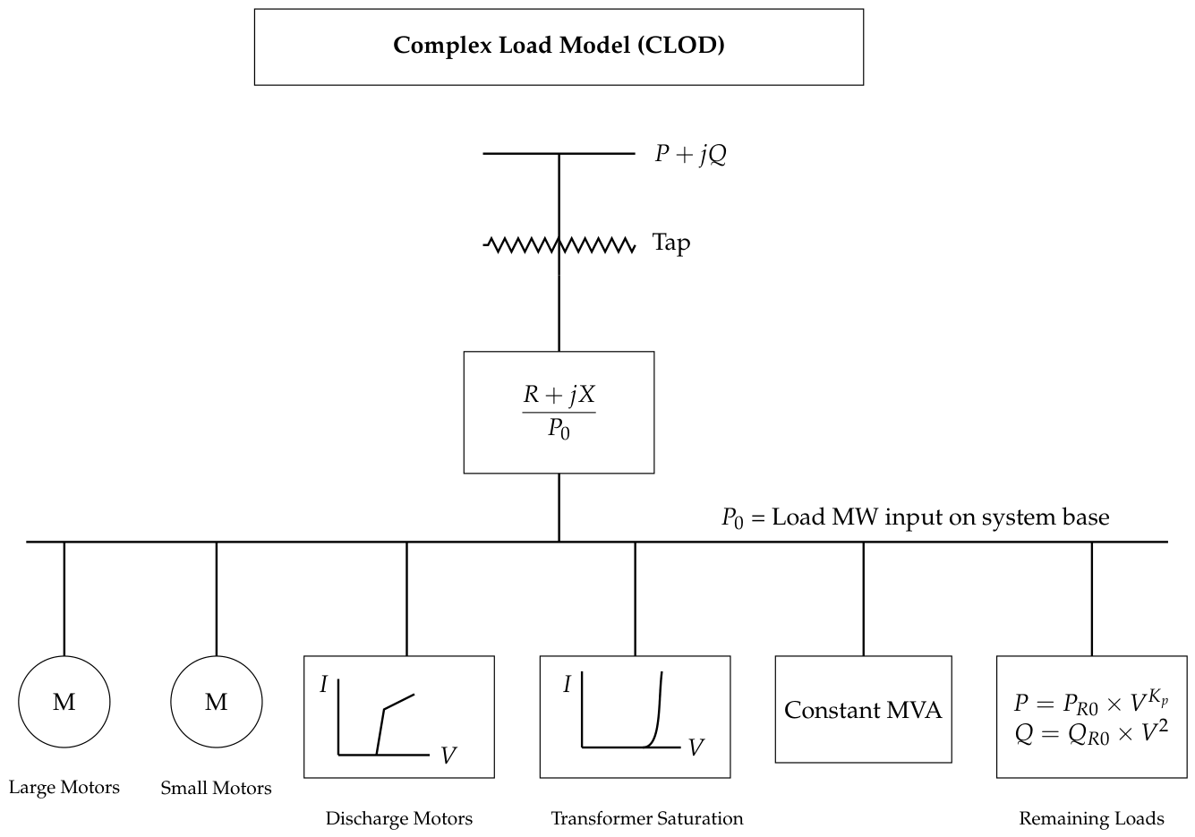
Figure 3.
Typical architecture of hyperscale datacenter.
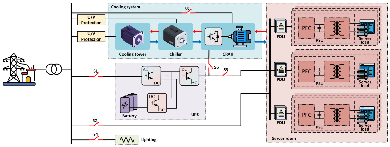
Figure 4.
Cease and reconnect logic of the data center.
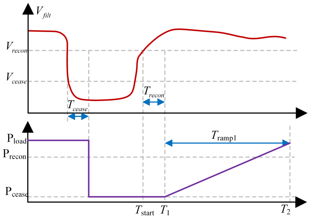
Figure 5.
100 MW data center model.
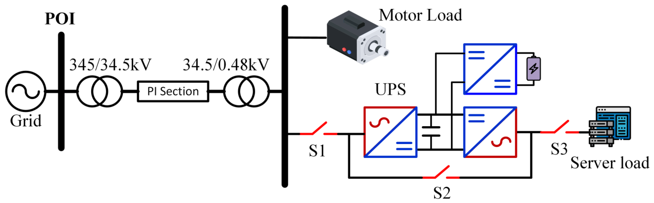
Figure 6.
LVRT response of the 100 MW data center model: (a) POI voltage and active power imported from the grid, (b) server load terminal voltage and active power by grid, and (c) motor load terminal voltage and active power.
Figure 6.
LVRT response of the 100 MW data center model: (a) POI voltage and active power imported from the grid, (b) server load terminal voltage and active power by grid, and (c) motor load terminal voltage and active power.
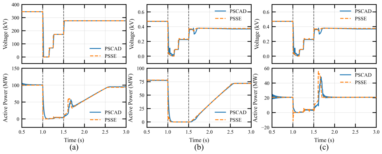
Figure 7.
HVRT response of the 100 MW data center model: (a) POI voltage and active power imported from the grid, (b) server load terminal voltage and active power by grid, and (c) motor load terminal voltage and active power.
Figure 7.
HVRT response of the 100 MW data center model: (a) POI voltage and active power imported from the grid, (b) server load terminal voltage and active power by grid, and (c) motor load terminal voltage and active power.
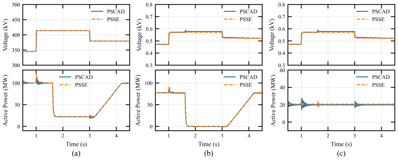
Figure 8.
1 GW data center model.
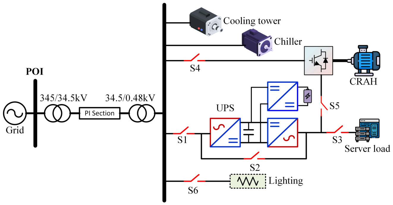
Figure 9.
EMT response of the 1 GW data center under a three-phase-to-ground fault: (a) POI voltage, (b) POI active power, (c) POI reactive power, (d) cooling-system active power, (e) VSD active power, (f) active power supplied to the IT load by the grid and UPS.
Figure 9.
EMT response of the 1 GW data center under a three-phase-to-ground fault: (a) POI voltage, (b) POI active power, (c) POI reactive power, (d) cooling-system active power, (e) VSD active power, (f) active power supplied to the IT load by the grid and UPS.
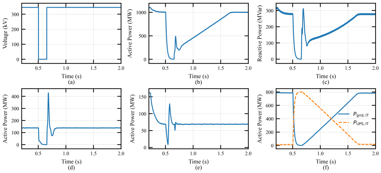
Figure 10.
Comparison of generator rotor-angle responses obtained from component-level and performance-level data center models during a large disturbance. The close agreement between the two representations demonstrates that appropriately parameterized performance-level models can accurately capture the bulk-system dynamic behavior of hyperscale data center loads while significantly reducing model complexity.
Figure 10.
Comparison of generator rotor-angle responses obtained from component-level and performance-level data center models during a large disturbance. The close agreement between the two representations demonstrates that appropriately parameterized performance-level models can accurately capture the bulk-system dynamic behavior of hyperscale data center loads while significantly reducing model complexity.
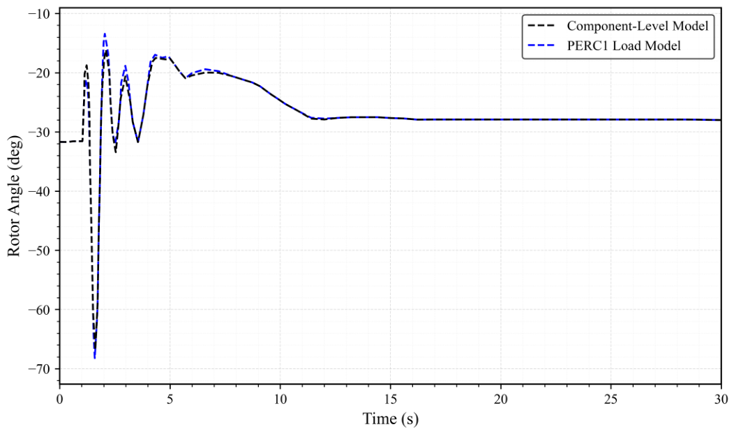
Figure 11.
Single load infinite bus (SLIB) system used for validation of large-load dynamic models at the point of interconnection (POI).
Figure 11.
Single load infinite bus (SLIB) system used for validation of large-load dynamic models at the point of interconnection (POI).
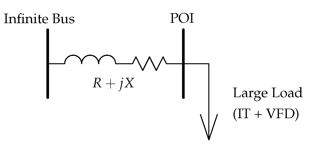
Figure 12.
Comparison of the dynamic behavior of the IT and VFD load representations under disturbance conditions.
Figure 12.
Comparison of the dynamic behavior of the IT and VFD load representations under disturbance conditions.
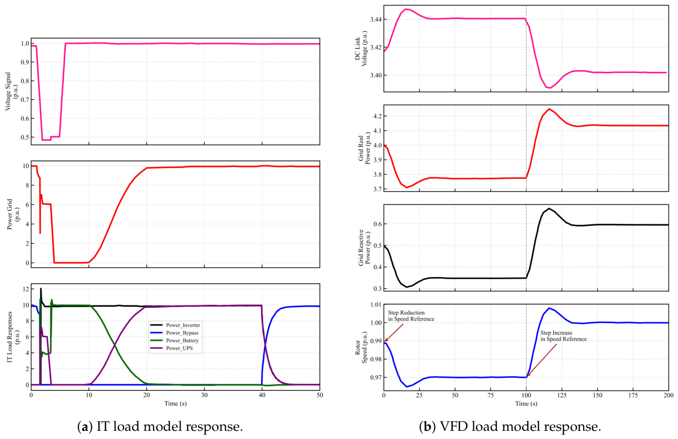
Figure 13.
Performance of a UPS-based IT load during the transmission fault.
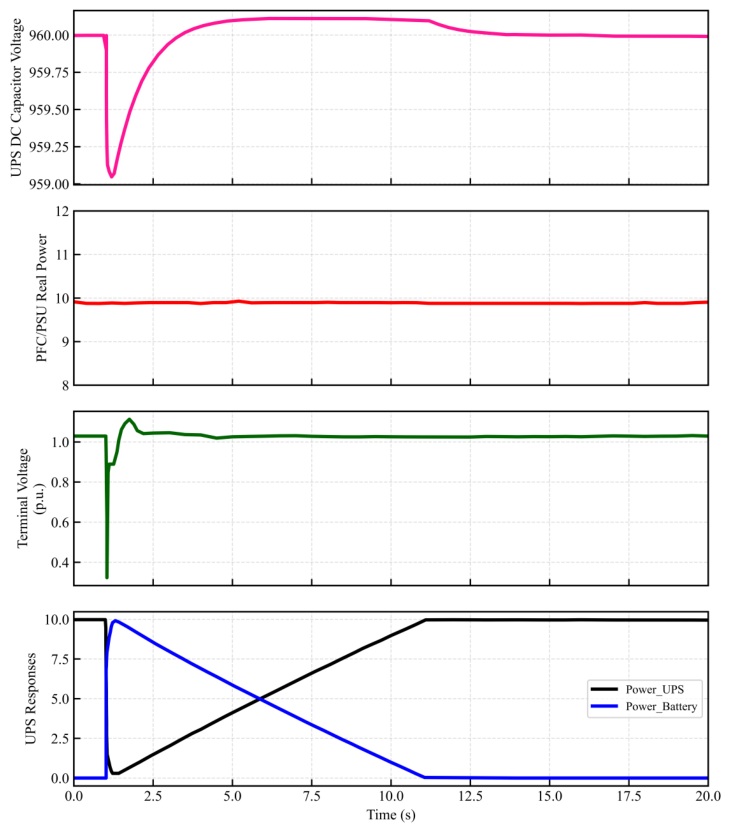
Figure 14.
Dynamic response of the VFD load during the same disturbance.
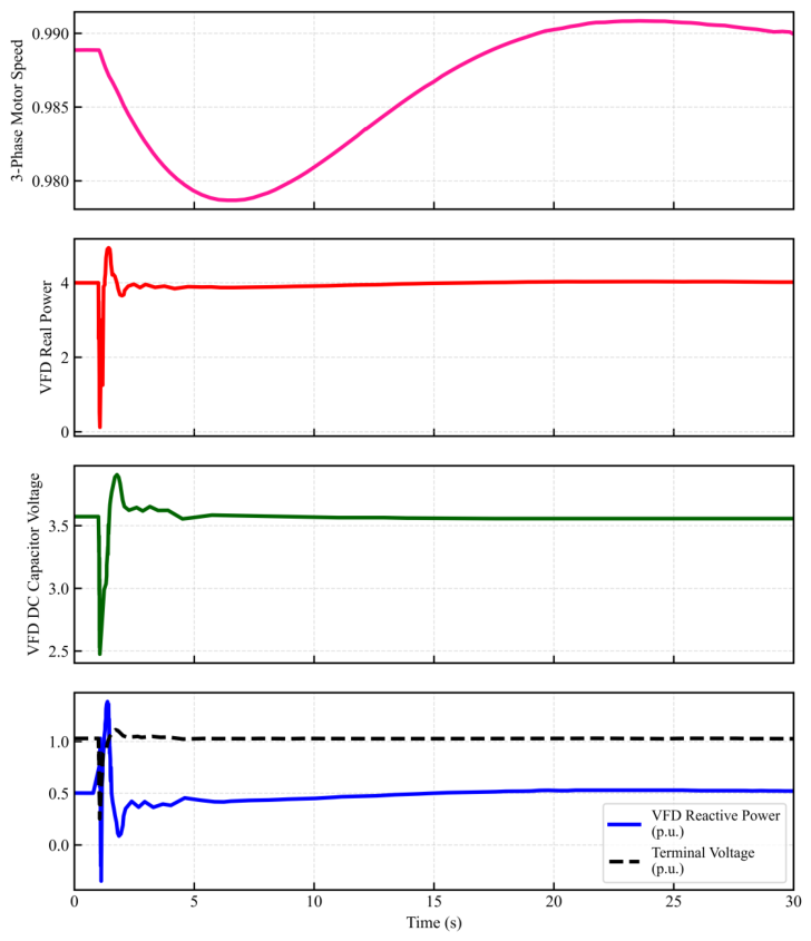
Figure 15.
The rotor-angle response of nearby synchronous generators following the same fault.
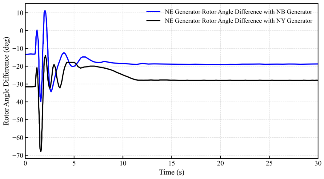
Figure 16.
AI load-cycling profile used to represent periodic variations in large computational load demand.
Figure 16.
AI load-cycling profile used to represent periodic variations in large computational load demand.
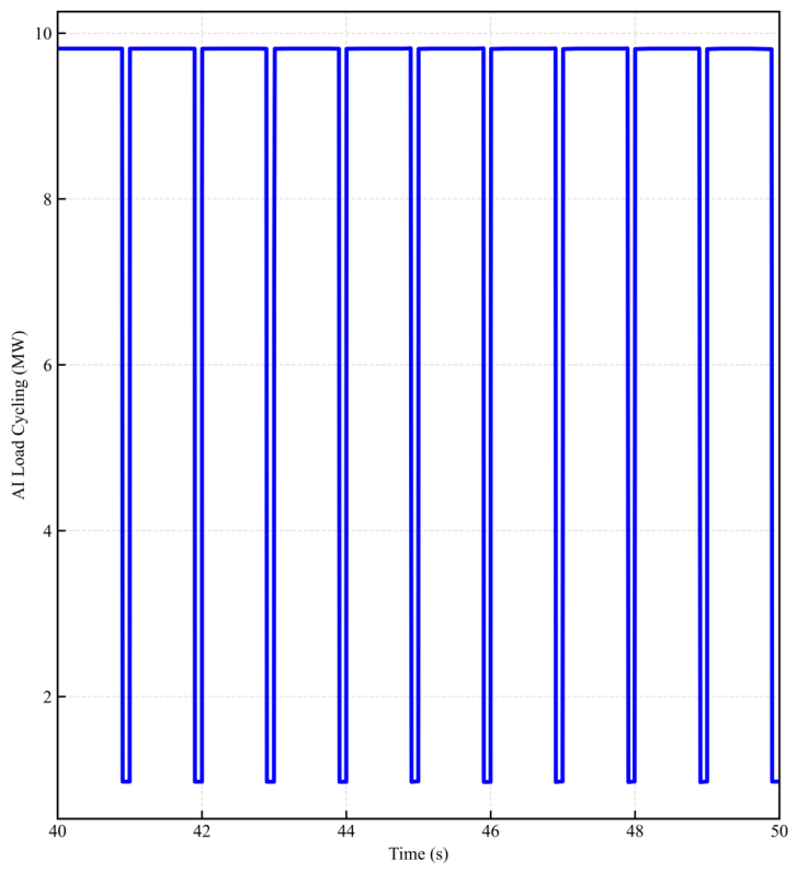
Figure 17.
Mitigation strategies for AI-driven load cycling in hyperscale data centers. (a) Rack-level supercapacitors provide short-duration energy storage that smooths rapid load variations and reduces local power fluctuations. (b) E-StatCom devices provide fast dynamic voltage support and damping, reducing the propagation of load-induced oscillations into the bulk power system and improving generator stability.
Figure 17.
Mitigation strategies for AI-driven load cycling in hyperscale data centers. (a) Rack-level supercapacitors provide short-duration energy storage that smooths rapid load variations and reduces local power fluctuations. (b) E-StatCom devices provide fast dynamic voltage support and damping, reducing the propagation of load-induced oscillations into the bulk power system and improving generator stability.
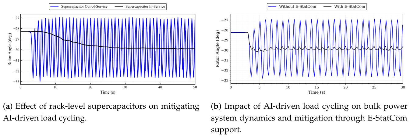
Figure 18.
System frequency response following a large-load disturbance with and without BESS support. The BESS reduces frequency excursions and improves damping by rapidly absorbing excess generation following the disturbance.
Figure 18.
System frequency response following a large-load disturbance with and without BESS support. The BESS reduces frequency excursions and improves damping by rapidly absorbing excess generation following the disturbance.
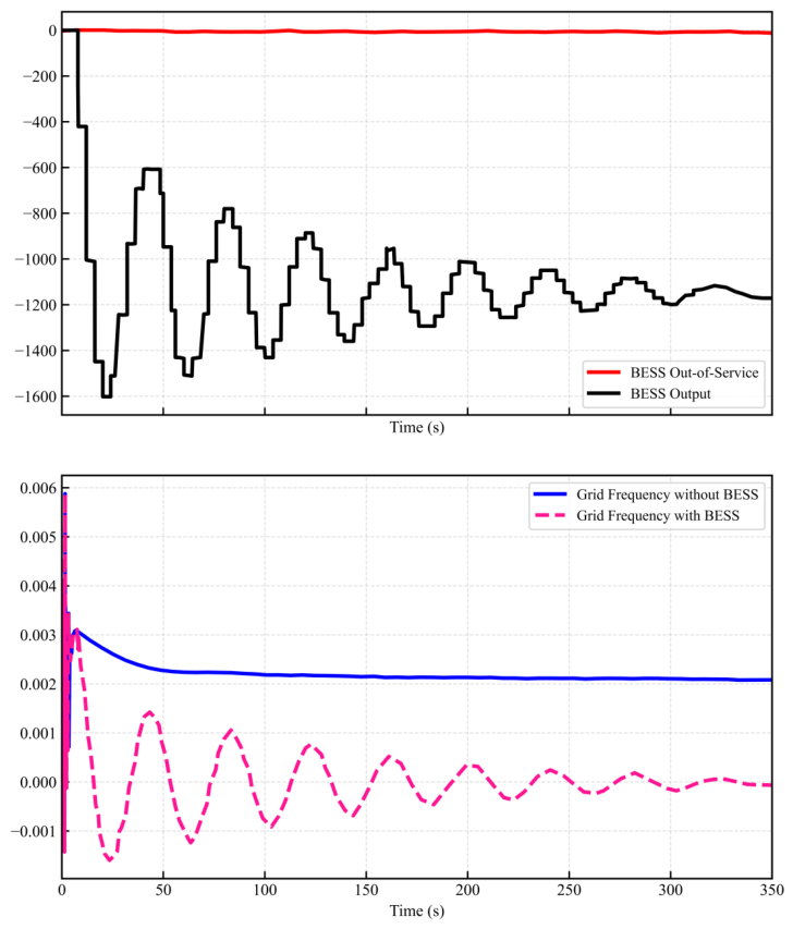
Figure 19.
Inter-area tie-line power flow (NY-NE), generation reduction, and large-load power response following a fault-induced large-load trip. Excess generation caused by the load disconnection is redistributed through tie-line exports and generation control actions.
Figure 19.
Inter-area tie-line power flow (NY-NE), generation reduction, and large-load power response following a fault-induced large-load trip. Excess generation caused by the load disconnection is redistributed through tie-line exports and generation control actions.
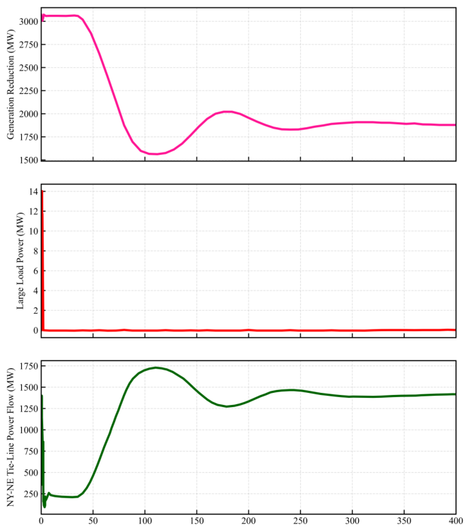

Table 1.
Summary of large load definitions and thresholds across major North American regulatory entities and utilities
Table 1.
Summary of large load definitions and thresholds across major North American regulatory entities and utilities
| Organization | Type | Threshold / Definition |
|---|---|---|
| ERCOT | ISO/RTO | ≥75 MW (standalone); ≥20 MW (co-located with generation) |
| NYISO | ISO | ≥10 MW at ≥115 kV; or ≥80 MW below 115 kV |
| Xcel Energy | Utility | ≥50 MW transmission-connected large loads; LVRT/HVRT, LFRT/HFRT, six automatic reclose ride-through events, reactive-current priority during faults, and ramp rate ≤20 MW/min |
| Dominion Energy | Utility | ≥100 MW at a single transmission interconnection point |
| CPS Energy | Utility | ≥40 MW |
Table 2.
Comparison of major load models for transmission planning applications.
| Model | Dynamic | Relative | Data | Power | Voltage | Transient | EMT | Typical Large Load |
|---|---|---|---|---|---|---|---|---|
| Behavior | Complexity | Requirement | Flow | Stability | Stability | Studies | Application | |
| ZIP | No | Low | Low | ✓ | Limited | No | No | Conventional planning loads |
| Induction Motor (IM) | Yes | Medium | Medium | Limited | ✓ | ✓ | No | Motor-dominated industrial facilities |
| ZIP+IM | Yes | Medium | Medium | ✓ | ✓ | ✓ | No | Industrial and commercial loads |
| CLOD | Yes | High | High | ✓ | ✓ | ✓ | No | Utility dynamic stability assessments |
| CMLD | Yes | High | High | ✓ | ✓ | ✓ | No | FIDVR and detailed load dynamics studies |
| LDEV1 | Yes | High | High | ✓ | ✓ | ✓ | Limited | EV charging stations and electronic loads |
| PERC1 | Yes | High | High | ✓ | ✓ | ✓ | Limited | Data centers and cryptocurrency mining loads |
| EMT Models | Full | Very High | Very High | No | ✓ | ✓ | ✓ | Data centers, electrolyzers, and weak-grid studies |
Table 3.
Recommended load models for common transmission planning studies
| Planning Study | Recommended Model | Primary Modeling Objective | Rationale |
|---|---|---|---|
| Power Flow Analysis | ZIP | Steady-state voltage and power flow calculation | Computationally efficient representation of aggregate load behavior under normal operating conditions. |
| Thermal Loading and Congestion Analysis | ZIP | Transmission line and transformer loading assessment | Captures voltage-dependent demand effects while maintaining scalability for large network studies. |
| N-1 Contingency Analysis | ZIP / ZIP+IM | Post-contingency operating condition assessment | Provides adequate representation for screening studies and basic voltage sensitivity evaluation. |
| PV and QV Analysis | ZIP+IM | Voltage stability margin investigation | Includes motor dynamics that influence reactive power demand and voltage recovery. |
| Transient Stability Assessment | CLOD / CMLD | Generator-angle and dynamic system response | Represents dynamic load behavior, motor stalling, protection actions, and recovery characteristics. |
| FIDVR Analysis | CMLD | Short-term voltage recovery assessment | Explicitly captures motor stalling, thermal protection, feeder effects, and delayed voltage recovery phenomena. |
| Large Industrial Load Studies | CLOD / CMLD | Industrial facility dynamic behavior | Suitable for motor-dominated loads and complex industrial processes. |
| EV Charging Station Studies | LDEV1 | Power-electronic load dynamics | Represents voltage-dependent current limiting, ride-through behavior, and load cessation logic. |
| Data Center Dynamic Studies | PERC1 | Converter-dominated load response | Captures load tripping, reconnection, ride-through behavior, and aggregate power-electronic dynamics. |
| Hydrogen Electrolyzer Studies | PERC1 / EMT | Converter-based industrial process behavior | Suitable for electronically interfaced loads with fast control response characteristics. |
| Weak-Grid Assessment | EMT | Converter-control interaction analysis | Required when detailed control-system dynamics and low short-circuit-strength effects are important. |
| Harmonic and Resonance Analysis | EMT | High-frequency interaction assessment | Allows detailed representation of converter switching and electromagnetic interactions. |
| Grid-Interactive Flexible Load Studies | PERC1 / EMT | Demand flexibility and transmission flexibility assessment | Represents curtailment, ride-through, reconnection, and fast load-modulation capabilities. |
Table 4.
Data center operating modes under different grid voltage conditions.
| Operation mode | (p.u.) | |||||||
|---|---|---|---|---|---|---|---|---|
| Normal eco mode | N/A | on | on | off | on | on | off | |
| Double conversion mode | 500 ms | on | off | on | on | off | off | |
| Battery mode | 20 ms | off | off | on | on | off | on | |
| Battery mode | 500 ms | off | off | on | on | off | on |
Table 5.
Key challenges and future priorities for large-load modeling
| Challenge | Priority | What’s Needed | Primary Stakeholders |
|---|---|---|---|
| Data Availability, Validation, and Benchmarking | High | Standardized validation methodologies, benchmark disturbance events, and open-access datasets | Utilities, regulators, transmission planners |
| Power-Electronics-Dominated Large Loads | High | Computationally efficient and vendor-independent representations of converter-dominated loads | Planners, load customers, protection engineers |
| EMT–Phasor Coordination | High | Scalable hybrid simulation frameworks and consistent cross-platform parameterization | Transmission planners, software vendors |
| Large Load Uncertainty Characteristics | High | Probabilistic planning, scenario-based forecasting, and adaptive model development | Long-term planners, load forecasters |
| Digital Twins | Medium | Integration of SCADA, PMU, and facility telemetry into continuously updated models | Utilities, facility operators, researchers |
| Open Benchmark Systems and Testing Frameworks | Medium | Representative large-load models, disturbance datasets, and reference implementations | Research community, software vendors, regulators |
| Harmonization of Large-Load Requirements Across Jurisdictions | High | Common modeling standards, interconnection requirements, benchmark validation procedures, and internationally consistent technical performance criteria | Regulators, TSOs/RTOs, utilities, standards organizations, large-load developers |
Disclaimer/Publisher’s Note: The statements, opinions and data contained in all publications are solely those of the individual author(s) and contributor(s) and not of MDPI and/or the editor(s). MDPI and/or the editor(s) disclaim responsibility for any injury to people or property resulting from any ideas, methods, instructions or products referred to in the content. |
© 2026 by the authors. Licensee MDPI, Basel, Switzerland. This article is an open access article distributed under the terms and conditions of the Creative Commons Attribution (CC BY) license (http://creativecommons.org/licenses/by/4.0/).
Copyright: This open access article is published under a Creative Commons CC BY 4.0 license, which permit the free download, distribution, and reuse, provided that the author and preprint are cited in any reuse.