

Submitted:
19 October 2026
Posted:
20 October 2026
You are already at the latest version
Abstract
The state of a perovskite precursor ink is set by how its solvents coordinate the precursors, yet the roles of individual solvents in green binary mixtures remain poorly understood. Here we examine how 2-methoxyethanol (2Me) and 1,3-dimethyl-2-imidazolidinone (DMI) share the solvation of the four precursor components of a formamidinium–methylammonium (FA–MA) lead iodide–bromide ink: PbI₂, PbBr₂, FAI and MABr. Cluster–continuum DFT calculations (r²SCAN-3c/SMD) of the exchange of 2Me for DMI in the first solvation shell show that PbI₂ prefers DMI, whereas PbBr₂, FAI and MABr prefer 2Me (+4.7, +4.2 and +8.4 kJ mol⁻¹ per DMI); in FAI and MABr, 2Me donates O–H···X⁻ hydrogen bonds to the halide anion. A thermodynamic model built on these energies points to 2Me-rich mixtures (about 10–20 vol% DMI) as the best compromise. All 2Me/DMI mixtures wet the polymer PTAA, with the contact angle falling from 24.7° (2Me) to 13.3° (DMI). Without an anti-solvent (gas quenching only), the 2Me:DMI ink gives on PTAA a film with larger and more uniform grains than the DMF:DMSO ink, with the same absorption onset (776 nm). Together with literature data on blade-coated films and modules, these results support 2Me/DMI as a solvent system for anti-solvent-free, large-area processing of FA–MA perovskites.
Keywords:
perovskite solar cells
; green solvents
; 2-methoxyethanol
; 1
; 3-dimethyl-2-imidazolidinone
; precursor solvation
; density functional theory
; wettability
; anti-solvent-free processing
1. Introduction
Metal halide perovskites are among the most studied materials for solution-processed photovoltaics. Mixed-cation compositions, in which formamidinium (FA⁺) and methylammonium (MA⁺) share the A site and bromide partly replaces iodide, stabilized the perovskite phase of FAPbI₃ and gave n–i–p solar cells with efficiencies above 18% [1]. In 2026, a certified steady-state efficiency of 27.17% was reported for n–i–p cells [2]. Large-area devices lag behind: the latest efficiency tables report 22.1% for a 0.08 m² module and 19.3% for a 0.72 m² module [3]. Reproducible fabrication and scale-up remain difficult, because film formation is sensitive to the state of the precursor solution and to the way the solvent leaves the wet film.
The solvent is an active component of the ink and not only a dissolution medium. In DMF/DMSO inks, DMSO binds PbI₂ strongly and, because of its high boiling point, stays in the wet film, so the film remains undersaturated for a long time and, if left to dry, crystallizes slowly from few nuclei into a rough, incomplete layer. An anti-solvent drip removes DMF and DMSO from the wet film within seconds, raises the supersaturation abruptly and induces dense nucleation of a solvated intermediate, which is converted into the perovskite on annealing [4]; the Lewis-base adduct of PbI₂ with DMSO delays crystallization and improves reproducibility [5]. DMF/DMSO inks therefore need an anti-solvent or an equivalent fast quench, and its application is hard to make uniform over large areas. Precursor solutions are generally colloidal dispersions, and their state controls crystallization kinetics and film morphology [6,7]. How strongly a solvent coordinates Pb²⁺ correlates with its Gutmann donor number [8], and sulfur-donor solvents bind Pb²⁺ more strongly than oxygen-donor solvents [9]; solvated iodoplumbate complexes in DMSO and DMF have been identified by combined DFT and UV–vis studies [10]. A donor-number picture, however, considers only the interaction with Pb²⁺ and ignores hydrogen-bond donation by the solvent. The interaction with the organic cation can also decide which intermediate forms: NMP interacts more strongly than DMSO with formamidinium and stabilizes a FAI–PbI₂·NMP adduct [11]. For FA/MA and I⁻/Br⁻ mixtures, crystallization from DMF and DMSO proceeds through several solvate phases that are set by the composition of the solution [12], and in binary mixtures the most volatile solvent dominates evaporation, so that the solvent ratio at nucleation differs from that in the ink [13].
The need for a fast supersaturation step follows from the LaMer mechanism of nucleation and growth, the framework generally used for perovskite films [14,15]. As the solvent leaves, the solute concentration rises; nucleation starts only when it exceeds a critical supersaturation and stops as soon as the nuclei consume the solute and the concentration falls below it, after which the existing nuclei only grow. A short, sharp burst of nucleation gives many nuclei at once and a dense film of uniform grains, whereas a slow rise spreads nucleation over time and gives few, non-uniform nuclei and incomplete coverage. The anti-solvent drip creates the burst by extracting the solvent abruptly, and gas quenching does so by accelerating evaporation. Where an anti-solvent cannot be applied uniformly, as in large-area coating, the burst has to come from the ink itself, that is, from the volatility of its solvents and from how strongly they bind the precursors, which sets how far the concentration must rise before nucleation. This is why the solvation of the precursors, and not only the film, has to be understood.
The DMF/DMSO pair, the most widely used, has further drawbacks. DMF is toxic, and the DMSO retained in the wet film is the main cause of dewetting of precursor solutions on hydrophobic polymer hole-transport layers such as PTAA in gas-quenching deposition: DMF evaporates first, the DMSO fraction in the wet film rises, and the contact angle approaches that of pure DMSO (45.6° on PTAA), which leaves pinholes [16]. 2-Methoxyethanol (2Me), a more volatile solvent, was introduced for methylammonium lead halide solar cells, where it gave smaller crystals and better surface coverage than DMF [17]. Weakly bonded I⁻ ions and cluster complexes were found in 2Me inks of MAPbI₃, and in FAPbI₃ the cluster ratio was linked to the kinetics of δ-phase formation [18,19]. Combining 2Me with the donor solvent DMI keeps fast drying and adds a carbonyl donor for Pb²⁺. For an ink of (FAPbI₃)₀.₉₅(MAPbBr₃)₀.₀₅, a 2Me/DMI mixture with 75 μL of DMI per mL gave pinhole-free films over more than 100 cm², n–i–p cells of 23.4% and modules of 20.1% efficiency, ahead of DMF/DMSO and 2Me/NMP inks [20]. Desorption measurements showed that DMI is removed completely at 100 °C and leaves the film at a higher temperature than NMP, which points to stronger binding to PbI₂, whereas DMSO remains in the film after 1 h at 100 °C [20].
That work was a process study, and it is still unclear how 2Me and DMI divide their roles among the four components of a FA/MA lead iodide–bromide ink: PbI₂, PbBr₂, FAI and MABr. The hydroxyl group of 2Me can donate hydrogen bonds to halide anions, whereas DMI is an aprotic carbonyl donor, so the preferred solvent may differ from one precursor to another. Cluster–continuum models, which combine explicit first-shell solvent molecules with a dielectric continuum [21], are suited to this question. This work concerns the inverted p–i–n architecture, in which the perovskite ink is cast on a hydrophobic hole-transport polymer, here PTAA. The aim is to establish the molecular and processing basis for using 2Me/DMI as a solvent system for anti-solvent-free film formation over large areas. We use cluster–continuum DFT calculations to describe the exchange of 2Me for DMI in the first solvation shell of the four precursors and to derive their relative solubility as a function of the 2Me:DMI ratio, and we complement them with photographs and FTIR spectra of solutions in 2Me/DMI and in the reference solvents, UV–vis spectra and SEM images of films cast from 2Me:DMI and DMF:DMSO inks on PTAA, and contact-angle measurements on PTAA. We have not made complete solar cells or large-area films in this work, and statements about devices and large areas rely on literature data, which we state explicitly.
2. Materials and Methods
2.1. Materials
All chemicals were used as received without further purification. Lead(II) iodide (PbI₂, 99.99%) and lead(II) bromide (PbBr₂, 99.99%) were purchased from Tokyo Chemical Industry (TCI). Poly[bis(4-phenyl)(2,4,6-trimethylphenyl)amine] (PTAA, >99%), formamidinium iodide (FAI, >99.5%), methylammonium bromide (MABr, >99%), dimethylformamide (DMF, ≥99.9%), dimethyl sulfoxide (DMSO, ≥99.9%), toluene, anhydrous 2-methoxyethanol (2Me, 99.8%), 1,3-dimethyl-2-imidazolidinone (DMI, ≥99.0%), anhydrous N-methyl-2-pyrrolidone (NMP, 99.5%), methylammonium chloride (MACl, 99.99%), thiourea (≥99.999%, metals basis; Supelco) and poly(methyl methacrylate) (PMMA, Mw ≈ 100,000) were obtained from Sigma-Aldrich.
2.2. Substrate and Film Preparation
Glass substrates coated with indium tin oxide (ITO), 20 × 15 mm² in size, were cleaned in several steps. First, mechanical cleaning was performed with a 1:10 (v:v) aqueous solution of Hellmanex™ III, followed by ultrasonic cleaning in toluene, acetone, and isopropyl alcohol (IPA) for 10 minutes each. Substrates were dried under nitrogen flow and treated with oxygen plasma (100 W, 0.3 mbar) for 30 seconds to enhance surface wettability.
A hole transport layer (HTL) was deposited by spin-coating 100 μL of a PTAA solution (1.5 mg mL⁻¹ in toluene) at 6000 rpm for 30 s, followed by annealing at 100 °C for 10 min.
The perovskite precursor solution of composition (FAPbI3)0.95(MAPbBr3)0.05 was prepared in 2Me:DMI. For 1 mL of ink, PbI₂ (525.6 mg, 1.140 mmol), FAI (196.0 mg, 1.140 mmol), PbBr₂ (22.0 mg, 0.060 mmol), MABr (6.8 mg, 0.061 mmol) and MACl (6.0 mg, 0.089 mmol) were dissolved in 900 μL of 2Me and 76 μL of DMI. The mixture was kept at 60 °C for 30 min, cooled to room temperature and filtered through a 0.45 μm polytetrafluoroethylene (PTFE) syringe filter. After filtration, 17 μL of thiourea (100 mg mL⁻¹ in DMI; 1.7 mg) and 7 μL of poly(methyl methacrylate) (PMMA, 5 mg mL⁻¹ in DMI; 35 μg) were added, and the vial was gently shaken by hand until the additives were fully mixed. The final volume was 900 + 76 + 17 + 7 = 1000 μL; with the DMI introduced by the additive solutions (76 + 17 + 7 = 100 μL), the final solvent composition was 2Me:DMI = 900:100 μL (9:1 v/v); all other binary mixtures used in this work (2Me:NMP, DMF:DMSO and DMF:NMP) also had a volume ratio of 9:1. MACl was included because it stabilizes the intermediate phase and promotes the formation of the α-phase [22], and thiourea because it enlarges the grains, improves crystallinity and reduces pinholes in (FAPbI₃)₀.₈₅(MAPbBr₃)₀.₁₅ films [23].
For film deposition, 100 μL of the solution was spin-coated onto the PTAA layer in two steps: 1000 rpm for 10 s, then 5000 rpm for 60 s. Nitrogen gas quenching at 3 bar (0.3 MPa) was applied from the 10th second of the second step for 40 s, and the gas flow was stopped when the film had turned completely dark brown. The films were then annealed at 130 °C for 30 min. Reference films were prepared from the same precursor composition, with the same additives, dissolved in DMF:DMSO and processed under identical conditions.
2.3. Characterization
Solutions. Perovskite solutions (PVSK, 1 mL) and solutions of the individual precursors (MABr, FAI, PbI₂ and PbBr₂) were prepared at the concentrations of the ink (Section 2.2) in nine solvent systems: the single solvents DMF, DMSO, NMP, 2Me and DMI, and the binary mixtures DMF:DMSO, DMF:NMP, 2Me:DMI and 2Me:NMP. The PVSK solutions were photographed in glass vials. FTIR spectra of the solvents and of all solutions were recorded on an Invenio-S Fourier-transform infrared spectrometer (Bruker, Germany) in attenuated total reflectance (ATR) mode over 4000–400 cm⁻¹ at 4 cm⁻¹ resolution.
Films. Films were cast from the 2Me:DMI and DMF:DMSO inks as described in Section 2.2. Their absorption spectra were recorded over 550–900 nm on a Shimadzu UV-3600 spectrophotometer in transmission mode, using films deposited on glass/ITO/PTAA substrates (glass/ITO/PTAA/perovskite); a bare glass/ITO substrate was used as the reference. The spectra were smoothed with a Savitzky–Golay filter (21 nm window, third-order polynomial). The absorption onset was taken as the intersection of the tangent at the steepest point of the absorption edge with the baseline above the edge. The surface morphology of the films was examined with a JSM-IT210 scanning electron microscope (SEM; JEOL, Japan) in secondary-electron mode under high vacuum, at an accelerating voltage of 8 kV, a working distance of 11.0 mm and a magnification of 8000×; images were acquired with the InTouchScope software. For presentation, the images were denoised with a non-local-means filter and their contrast was stretched.
Wetting. Static contact angles were measured on a KRÜSS DSA25 drop-shape analyzer (KRÜSS GmbH, Germany) by the sessile-drop method at 20.0 °C in air. Drops (2 μL; three per composition) of 2Me/DMI mixtures (2Me:DMI from 10:0 to 0:10 by volume, in steps of 1) were placed on PTAA films prepared as in Section 2.2, and the angle was taken from the fitted drop profile at the moment of contact (0.00 s) as the mean of the left and right angles and of the three drops.
2.4. Computational Details
All quantum-chemical calculations were performed with ORCA 6.1.1 [24]. Each solvate cluster was treated in three steps. Initial geometries were optimized with GFN2-xTB [25], in the gas phase for lead halides and in the ALPB implicit model (methanol) for ion pairs, which prevents N–H···X⁻ proton transfer in the gas phase. The geometries were then re-optimized with r²SCAN-3c [26] and the SMD implicit solvation model [27], with the def2 effective core potential on Pb and the continuum parametrized as 2Me for all clusters. The thermal correction to the free energy, (G − Eel), was obtained from GFN2-xTB harmonic frequencies at 298.15 K, with the quasi-RRHO treatment of low-frequency modes [28,29]. The free energy of each structure is
The first solvation shell was described by explicit solvent molecules and the rest of the medium by a dielectric continuum (cluster–continuum approach [21]). Further details of the protocol are given in Section S1 of the Supporting Information.
Species in solution. Each precursor was considered separately, as if dissolved alone in the solvent. The species assumed for each follows from the nature of its bonds. PbI₂ and PbBr₂ are polar covalent halides of the soft Lewis acid Pb²⁺, which has a flexible, high coordination number and gains energy by binding donor atoms of the solvent; they were therefore treated as neutral molecular solvate complexes PbX₂(solvent)4, in which both Pb–X bonds are kept and the solvent donor atoms occupy the remaining coordination sites. In the optimized structures the Pb–X distances remain at 3.10–3.16 Å (Pb–I) and 2.81–2.86 Å (Pb–Br) for every composition (Figure S1b), so the halides stay bound to Pb and are not released as free ions. FAI and MABr, in contrast, are ionic salts, in which cation and halide are held by electrostatic attraction. At the contact distance of about 3.8 Å, this attraction amounts to 1389/(ε·3.8) ≈ 22 kJ mol⁻¹ in 2Me (ε = 16.9) and ≈ 10 kJ mol⁻¹ in DMI (ε = 37.6), several times kT (2.5 kJ mol⁻¹ at 298 K), and the Bjerrum length (33 and 15 Å, Section S2 of the Supporting Information) exceeds the contact distance; in these solvents the ions therefore remain associated as contact ion pairs and not as free solvated ions, and the contact ion pair was taken as the ionic species. Free ions, solvent-separated pairs and iodoplumbate anions (PbX₃⁻, PbX₄²⁻), which form when halide from FAI or MABr is added to PbX₂, were not included, so the model describes each precursor separately and not the complete ink.
Solvate cluster models. For PbI₂ and PbBr₂ the coordination bond between Pb²⁺ and the O-donor atom of the solvent is decisive, and strong Lewis bases are needed to dissolve the halides [5,9]. The solvent properties used in the model are collected in Table 1.
Lead halides were modelled as neutral octahedral solvate complexes PbX₂(2Me)4−b(DMI)b (X = I, Br; b = 0–4), with the two halides in axial positions and four solvent molecules in the equatorial plane; for b = 2 the cis and trans isomers were calculated separately. FAI and MABr were treated as contact ion pairs (see above and Section S2 of the Supporting Information). Their first solvation shell has four sites (n = 4): two cation sites at N–H groups, to which the solvent O atom binds through N–H···O hydrogen bonds, and two anion sites around the halide, where 2Me binds through O–H···X⁻ hydrogen bonds, whereas aprotic DMI can form only weak C–H···X⁻ contacts. Isomers were calculated separately for each number of DMI molecules at the cation (c = 0–2) and anion (a = 0–2) sites, with b = c + a and statistical weight g = C(2,c)·C(2,a). Free 2Me and DMI molecules were calculated with the same protocol as each series.
Thermodynamic model. Solubility in the mixed solvent was derived from ligand-exchange equilibria without calculating the solid phase. For a dissolved species M (PbI₂, PbBr₂, FAI or MABr), the stepwise replacement of 2Me by DMI in the first shell is
with free energy
The number of molecules is conserved, so no standard-state correction is needed. Isomers with the same b are combined by Boltzmann weighting,
where gi is the statistical weight. The concentration of each complex in a saturated solution is
where φ is the volume fraction of DMI, Sref is the solubility in pure 2Me, CDMI and C2Me are the pure-liquid concentrations (Table 1), and a2Me and aDMI are the activities of the unbound solvents, found self-consistently from the mass-balance equations (Section S3 of the Supporting Information, Equations (S1) and (S2); Equation (5) is also derived there). DFT gives only relative quantities, so relative solubilities Ssat(φ)/Ssat(0) are reported. The sensitivity to errors in ΔGb was estimated by shifting it by ±4 kJ mol⁻¹ per DMI molecule, the typical uncertainty of the r²SCAN-3c/SMD level. The model assumes ideal mixing of the solvents and a precipitating solid that is the pure precursor, and it neglects iodoplumbate species (PbX₃⁻, PbX₄²⁻).
3. Results and Discussion
3.1. Structure of the Solvate Clusters
Figure 1 shows the most stable solvate cluster at each step of the exchange series. In PbI₂ and PbBr₂, Pb²⁺ departs from the initial octahedral coordination: part of the 2Me binds Pb through two oxygen atoms (hydroxyl and ether), and another part moves to the second shell and binds the halide through O–H···X hydrogen bonds. In PbI₂ the two iodine atoms change from trans to cis from b = 2 onward, and the mean Pb–I distance increases from 3.10 to 3.16 Å with b (Figure S1b), which indicates that stronger coordination of DMI to Pb weakens the Pb–I bond; the Pb–Br distance hardly changes. In FAI and MABr the cation and anion stay a contact ion pair. DMI first occupies the cation sites (c = b, a = 0 for b ≤ 2), and 2Me keeps O–H···X⁻ hydrogen bonds around the anion; the O–H···Br⁻ distance (2.31–2.35 Å) is markedly shorter than O–H···I⁻ (2.61–2.70 Å) (Figure S1d), so bromide forms stronger hydrogen bonds with 2Me.
3.2. Energetics of Ligand Exchange
The successive exchange free energies (Figure 2) divide the four precursors into two groups. For PbI₂, ΔGb is negative and drops quickly for the first two DMI molecules (−22.4 and −33.7 kJ mol⁻¹ at b = 1 and 2); further exchanges give almost no energy (−31.7 and −34.5 kJ mol⁻¹ at b = 3 and 4). DMI thus displaces 2Me from the first shell of PbI₂, but the effect saturates after the second DMI molecule. For PbBr₂, FAI and MABr the full-exchange energy is positive (ΔG4 = +18.8, +16.6 and +33.5 kJ mol⁻¹), so 2Me is the better solvating solvent.
For FAI and MABr this follows from the O–H···X⁻ hydrogen bonds that 2Me forms with the halide anion. At b ≤ 2, placing DMI at an anion site is unfavorable: the isomers with a = 1 and a = 2 lie 9.5–14.8 kJ mol⁻¹ (FAI) and 2.1–13.5 kJ mol⁻¹ (MABr) above the a = 0 isomer, whereas placing DMI at a cation site is favorable for FAI (ΔG2 = −5.5 kJ mol⁻¹ for c = 2, a = 0). The calculations thus show the opposite roles of the two solvents: DMI solvates the cation, and 2Me solvates the anion. Because bromide is a stronger hydrogen-bond acceptor than iodide, the effect is stronger in MABr, whose ΔGb stays positive for all b.
For PbBr₂ the preference for 2Me may likewise be related to O–H···Br hydrogen bonds (Figure 1b). The value at b = 1 (+36.3 kJ mol⁻¹), however, is higher than that at b = 2 (+13.8 kJ mol⁻¹), an irregularity unusual for a stepwise exchange that is accompanied by a sharp increase in the mean Pb–O distance (Figure S1a). The b = 1 complex may therefore sit in a local minimum of the conformer search, and the quantitative PbBr₂ values should be regarded as less certain than those of the other precursors.
3.3. Relative Solubility in the Mixed Solvent
The relative solubility Ssat(φ)/Ssat(0) calculated from Equation (5) and the mass balance is shown in Figure 3. For PbI₂ the solubility rises steeply on adding DMI: 10 vol% DMI increases it by a factor of about 1.5·10⁴, and the curve levels off at about φ = 40%. Because these numbers depend exponentially on ΔGb, the ±4 kJ mol⁻¹ uncertainty changes them by several orders of magnitude (shaded band in Figure 3a), and the reliable conclusion is the shape of the curve, a steep rise at small DMI fraction followed by saturation, in line with Figure 2. For PbBr₂, FAI and MABr, in contrast, the solubility decreases as DMI is added. In the 1:1 mixture the solubility of PbBr₂ and MABr is about 15–16 times lower than in pure 2Me, whereas that of FAI falls more slowly (2.6-fold in the 1:1 mixture, 7.5-fold at φ = 80%). The solubility limit of PbI₂ is therefore expected at low DMI fractions and that of the other three precursors at high DMI fractions. The distribution of solvate complexes (Figure S2) shows the mechanism: in PbI₂ the all-2Me complex disappears at a very small DMI fraction and PbI₂(2Me)₂(DMI)₂ dominates between φ ≈ 5% and 60%, in FAI the mixed complex with two DMI molecules at the cation and two 2Me molecules at the anion is the main species from φ ≈ 30% to 95%, and in PbBr₂ and MABr the all-2Me complex dominates up to φ ≈ 80%. In a mixed solvent the two solvents together thus create the optimal solvation environment for FAI.
3.4. Overall Solvation Preference and Composition Window
The full-exchange free energy per DMI molecule, ΔGn/n (Figure 4), summarizes the four precursors: −8.6 kJ mol⁻¹ for PbI₂ and +4.7, +4.2 and +8.4 kJ mol⁻¹ for PbBr₂, FAI and MABr. With the ±4 kJ mol⁻¹ uncertainty, the sign is unchanged for PbI₂ and MABr, whereas for PbBr₂ and FAI the error bar approaches zero, so the preference of these two precursors is weak. The calculations point to a trade-off: PbI₂ needs only a small DMI fraction, because its gain saturates after two DMI molecules, whereas the solubility of PbBr₂, FAI and MABr falls steadily as DMI is added. A 2Me-rich mixture therefore satisfies all four precursors best; in the model this corresponds to about 10–20 vol% DMI, with the exact limits depending on the target concentration and on a calibration point that DFT cannot supply (Section S3 of the Supporting Information). The ink used for the films (Section 2.2) lies at the 2Me-rich edge of this window, and its DMI content before the additive solutions, 76 μL per mL of ink, is close to the 75 μL found optimal for blade-coated films of the same composition [20].
3.5. Dissolution of the Precursors in 2Me/DMI and Reference Solvents
To test whether the 2Me/DMI mixture can hold the precursors in solution, perovskite solutions in green and conventional solvents were photographed (Figure 5). Besides 2Me:DMI and DMF:DMSO, the series contains two NMP-containing mixtures as controls: NMP is the Lewis-base co-solvent that was benchmarked against DMI in 2Me-based inks [20], it binds the formamidinium cation and stabilizes a FAI–PbI₂·NMP adduct [11], and DMF:NMP is its counterpart in the DMF-based pair. Comparing 2Me:NMP with 2Me:DMI, and DMF:NMP with DMF:DMSO, separates the effect of the co-solvent from that of the main solvent (2Me or DMF), and the single solvents show the contribution of each component. All solutions, including those based on 2Me, DMI, 2Me:DMI and 2Me:NMP, are clear and show no visible turbidity or precipitate, so the green solvents keep the precursors in solution, with no visible undissolved material, at the concentration of the ink (about 1.2 M Pb). The 2Me:DMI solution is pale yellow, like the DMF:DMSO reference, whereas the NMP-containing solutions (Figure 5d,i) are a deeper yellow-orange; this difference was not investigated here.
3.6. FTIR Spectra of the Precursor Solutions
Figure 6 compares the spectrum of the 2Me:DMI binary solvent with those of solutions containing MABr, FAI, PbI₂ and PbBr₂. The spectra show the C=O stretch of DMI at 1680 cm⁻¹, the C–O stretching bands of 2Me at 1120–1050 cm⁻¹ and the broad O–H band of 2Me near 3400 cm⁻¹, so both solvents remain available as donors in the mixture. The spectra of the conventional solvents and of the other formulations are given in Figure S4–S6 and are dominated by the same kind of solvent bands: ν(C=O) near 1660 cm⁻¹ for DMF and NMP, ν(S=O) near 1050 cm⁻¹ for DMSO and ν(O–H) near 3400 cm⁻¹ for 2Me. The DFT results predict that the carbonyl oxygen of DMI binds Pb²⁺ and the N–H groups of FA⁺ and MA⁺, and that the hydroxyl group of 2Me hydrogen-bonds to halide anions, so lower ν(C=O) and changed ν(O–H) would be expected. Within the reading accuracy of the plotted spectra, however, ν(C=O) is 1677–1680 cm⁻¹ for the solvent and for all four solutions (±3 cm⁻¹), and the broad O–H band shows no systematic shift; the same holds for the other solvents. Shifts caused by weak interactions in a strongly hydrogen-bonded medium are of the order of a few cm⁻¹, and the bands of bound solvent can overlap with those of the large excess of free solvent, so these spectra neither confirm nor contradict the calculated coordination pattern; they show that no new strong bands are formed and that the solvent bands are not changed by the precursors at this resolution.
3.7. UV–Vis Absorption of the Films
The absorption spectra of the perovskite films prepared from the 2Me:DMI and DMF:DMSO inks are compared in Figure 7. Both films have the absorption onset at 776 nm (1.60 eV; tangent method, Section 2.3), the steepest part of the edge at 760 nm and the same low background above 800 nm, so the choice of solvent does not change the position of the edge. The 2Me:DMI film absorbs more strongly at shorter wavelengths, with a steep rise below 570 nm, and shows weak shoulders near 575, 645, 665 and 685 nm that are absent from the DMF:DMSO spectrum. Stronger absorbance was likewise found for films from 2Me inks with an optimized DMI content [20]. A higher absorbance can reflect a thicker or more strongly scattering film. The shoulders are not features of a single-phase three-dimensional perovskite edge; they may come from additional absorbing species, such as residual intermediate or lower-dimensional phases, or from optical interference in the film, and their origin is not resolved by these data.
3.8. Wetting of PTAA by 2Me/DMI Mixtures
Figure 8 and Table S1 show the contact angle of the 2Me/DMI mixtures on PTAA (drop profiles in Figure S3). All compositions wet PTAA well, with angles between 24.7° for pure 2Me and 13.3° for pure DMI. The angle decreases monotonically as the DMI content rises. The largest single change occurs at the first addition of DMI (24.7° to 21.7° at 10 vol%); beyond this the angle falls almost linearly, by 0.6–1.5° per 10 vol% of DMI, and the total change over the whole range is 11.4°. For comparison, DMSO, DMF and NMP give 45.6°, 25.6° and 12.0° on PTAA [16] (a different PTAA film, so the values are comparable only in trend): pure DMI wets PTAA about as well as NMP and 2Me about as well as DMF, whereas DMSO wets it much worse.
In the composition window proposed from the calculations (10–20 vol% DMI), the contact angle changes only from 21.7° to 21.0°, a difference of 0.7° that is probably within the experimental uncertainty (the scatter of the three drops is not reported), so wetting does not discriminate between compositions inside the window; it only shows that none of them suffers from poor wetting. The wetting behavior also changes during drying, which is what matters in gas-quenching deposition: the volatile 2Me (boiling point 124 °C) leaves the wet film first and the DMI fraction (boiling point 225 °C) rises, so the contact angle falls towards that of pure DMI. In DMF:DMSO the opposite happens: DMF leaves first, and the angle approaches that of DMSO, the poorest wetting solvent [16]. A high DMI content, although it favors wetting, slows drying and may retain solvent in the film, so a mixture with 10–20 vol% DMI appears to be a reasonable compromise. The measurements were made with the solvent mixtures alone; the dissolved precursors can change the angle and the surface tension, which were not determined.
3.9. Film Morphology and Choice of the Reference Solvent
Choice of the two systems. Films were cast from 2Me:DMI and DMF:DMSO only, although nine solvent systems (five single solvents and four binary mixtures) were examined in solution. DMF:DMSO was taken as the reference because inks of this type are the basis of the solvent-engineering route [4,5], and in a direct comparison of inks with the same (FAPbI₃)₀.₉₅(MAPbBr₃)₀.₀₅ composition, 2Me/DMI gave the highest efficiency (23.45%) ahead of DMF/DMSO (22.73%) and 2Me/NMP (22.29%) [20]. NMP-containing mixtures were not taken to the film stage because the 2Me/NMP ink has a narrower processing window and a lower efficiency than 2Me/DMI [20] and DMF:NMP still contains the toxic DMF and is therefore not a green alternative. Single solvents were not taken to the film stage because the calculations show that neither 2Me nor DMI alone is the best solvent for all four precursors (Section 3.4), which is the reason for combining them; the single-solvent solutions served only to show the contribution of each component. The solution results do not separate the remaining formulations: all solutions are clear (Figure 5), the FTIR bands are not changed by the precursors (Figure 6), and the films from 2Me:DMI and DMF:DMSO have the same absorption onset at 776 nm (Figure 7). Both inks therefore give absorbers with the same band edge, so a difference between the films can be attributed to the solvent system and not to a different composition.
Morphology. Figure 9 compares the films. The film from DMF:DMSO (Figure 9a) consists of small, closely packed grains of about 0.4–1 μm, with clusters of bright elongated particles a few hundred nanometers long in some areas. The film from 2Me:DMI (Figure 9b) is built from larger grains of about 0.6–2 μm with well-defined boundaries and without such particles. Both films are continuous in the imaged areas and no pinholes are seen in either, so the images show a difference in grain size and homogeneity and not in coverage. The composition of the bright particles was not determined. A burst of nucleation gives many small grains, and slower nucleation gives fewer, larger ones (Section 1), so the different grain sizes may reflect different nucleation behavior of the two inks, but the present data do not resolve this. The wetting results point in the same direction: all 2Me/DMI mixtures wet PTAA (Figure 8), whereas DMSO is the poorest wetting solvent of the DMF/DMSO pair on PTAA, and dewetting caused by the DMSO fraction left in the wet film leads to pinholes in gas-quenching deposition [16]. The DMF:DMSO film imaged here shows no pinholes, so the SEM images neither show nor exclude this effect; the contact angle of the DMF:DMSO ink itself was not measured, and one area of each film was imaged. Both inks contain the same additives (MACl, thiourea and PMMA), so the difference cannot be attributed to them. Together, the DFT, wetting and SEM results indicate that, under the same gas-quenching conditions, the 2Me:DMI ink gives on PTAA a film of larger and more uniform grains than the DMF:DMSO ink in the imaged areas, which supports the use of a 2Me-rich mixture as a green alternative. Grain sizes are read from the scale bars of the images shown.
3.10. Implications for Large-Area, Anti-Solvent-Free Processing
Large-area coating places requirements on the ink that the results above address in part. First, the ink must stay dissolved at a high concentration. The 1.2 M inks in 2Me:DMI are clear (Figure 5), and the calculations explain why some DMI is needed and why only a little: DMI raises the solubility of PbI₂ by orders of magnitude, with most of the gain from the first two DMI molecules (Figure 2a, Figure 3a), whereas a 2Me-rich solvent keeps PbBr₂, FAI and MABr in solution (Section 3.4). The calculations give this trend and not the exact composition, because absolute limits need a solubility calibration point that DFT cannot supply (Section S3 of the Supporting Information). The composition rests on experiment: in blade-coated films of the same composition 25–50 μL of DMI per mL of ink gave pinholes because DMI was too little to retard nucleation, 125 μL gave defective films, and the optimum was 75 μL [20]. The DMI content therefore cannot be reduced without limit; the workable range is narrow and is of the order of 10 vol% DMI, consistent with the direction of the calculated trend but not derived from it.
Second, the wet film must spread completely. All 2Me/DMI compositions wet PTAA (Figure 8), and the film from 2Me:DMI is continuous and built from larger grains than the DMF:DMSO film (Figure 9). Third, the intermediate formed after solvent extraction must survive the time that large-area coating takes before annealing. For 2Me/DMI, no δ-phase and no growth of PbI₂ were found after 5 min in ambient air before annealing, whereas the DMF/DMSO intermediate (diethyl ether quenching) degraded to PbI₂ and the 2Me/NMP intermediate formed δ-phase [20]. This stability is consistent with the preference of PbI₂ for DMI found here (Figure 2a). DMI nevertheless leaves the film completely at 100 °C within about 10 min, whereas DMSO remains after 1 h [20].
Fourth, no anti-solvent is needed. Our films were formed by nitrogen gas quenching alone, and 2Me/DMI inks have been processed by air-flow-assisted blade coating, again without an anti-solvent, into films over more than 100 cm² and modules of 20.1% efficiency [20]. Gas quenching can possibly be reduced further. During natural drying, nucleation in 2Me/DMI starts after about 1 min and the intermediate forms over 1–5 min [20], and 2Me is volatile, so a 2Me-rich ink with the lowest DMI content that still dissolves PbI₂ might crystallize even without quenching, which would remove the main equipment requirement of the method. This is a hypothesis: it was not tested here, our films were gas-quenched, and low DMI contents led to fast, inhomogeneous crystallization under air quenching [20]. Films cast with systematically reduced DMI content, with and without quenching, on blade- or slot-die-coated areas, and the resulting solar cells, are the experiments that would decide it. We also note that 2Me is itself a hazardous solvent (a reproductive toxicant) that needs closed handling, so the benefit of the 2Me/DMI system lies in its processing (no anti-solvent, a volatile main solvent, complete removal of DMI at 100 °C) and not in the absence of hazard.
4. Conclusions
Cluster–continuum DFT calculations show that DMI and 2Me play different roles in the solvation of the four precursor components of a FA/MA lead iodide–bromide ink. PbI₂ prefers DMI, with most of the stabilization gained from the first two DMI molecules, whereas PbBr₂, FAI and MABr prefer 2Me. In FAI and MABr the preference follows from O–H···X⁻ hydrogen bonds between 2Me and the halide anion, while DMI preferentially solvates the cation. A thermodynamic model built on these free energies predicts that the solubility of PbI₂ rises steeply and then saturates on adding DMI, while the solubility of the other three precursors falls, so that a 2Me-rich mixture (about 10–20 vol% DMI) is the best compromise for a single ink. All 2Me/DMI mixtures wet PTAA (21–22° in the proposed window). Without an anti-solvent (gas quenching only), the 2Me:DMI ink gives on PTAA a continuous film of larger and more uniform grains than the DMF:DMSO ink in the imaged areas, with the same absorption onset (776 nm); no pinholes were found in either film in the imaged areas. Combined with literature data on blade-coated films and modules, these results support 2Me:DMI as a solvent system for anti-solvent-free, large-area processing, with a narrow, 2Me-rich composition range set by PbI₂ solubility on one side and by the solubility of the other precursors and the nucleation rate on the other. The calculations give relative solubilities only, assume ideal mixing of the solvents and use a continuum parametrized for 2Me. Large-area films, solar cells and modules, films with reduced DMI content with and without gas quenching, and the contact angle of the DMF:DMSO ink remain to be reported.
Supplementary Materials
The supporting information can be downloaded at the website of this paper posted on Preprints.org. It contains the detailed computational protocol (Section S1), the model of ion pairs (Section S2), the details of the thermodynamic model (Section S3), the geometric parameters (Figure S1) and speciation (Figure S2) of the clusters, the contact-angle data (Table S1, Figure S3) and the FTIR spectra of the precursors in the reference solvents (Figures S4–S6).
Author Contributions
Conceptualization, A.O.O.; methodology, A.O.O.; software, D.A.T.; validation, N.R.A. and A.O.O.; formal analysis, D.A.T., U.Kh.Y. and R.Yu.R.; investigation, U.B.E., U.Kh.Y., R.Yu.R. and D.A.T.; resources, N.R.A.; data curation, D.A.T. and R.Yu.R.; writing—original draft preparation, A.O.O.; writing—review and editing, A.O.O. and N.R.A.; visualization, A.O.O.; supervision, N.R.A.; project administration, A.O.O.; funding acquisition, N.R.A.. All authors have read and agreed to the published version of the manuscript.
Funding
This research was funded by the basic funding project “Creation of third-generation stable solar cells based on perovskites” of the Institute of Polymer Chemistry and Physics, Academy of Sciences of the Republic of Uzbekistan, and partially by the Uzbekistan–Turkey joint applied research project No. AL-9825036056, “Creation of efficient monolithic tandem silicon/perovskite solar cells”.
Data Availability Statement
The data presented in this study are available in the article and in the Supplementary Materials. Further raw data (FTIR, UV–vis, contact-angle and SEM files and the DFT output files) are available from the corresponding author on reasonable request.
Conflicts of Interest
The authors declare no conflicts of interest.
References
- Jeon, N. J.; Noh, J. H.; Yang, W. S.; Kim, Y. C.; Ryu, S.; Seo, J.; Seok, S. I. Compositional engineering of perovskite materials for high-performance solar cells. Nature 2015, 517, 476–480. [Google Scholar] [CrossRef] [PubMed]
- Wang, D.; et al. Continuously graded-doped SnO₂ for efficient n–i–p perovskite solar cells. Nature 2026. [Google Scholar] [CrossRef] [PubMed]
- Green, M. A.; Dunlop, E. D.; Yoshita, M.; et al. Solar cell efficiency tables (Version 68). Joule 2026. [Google Scholar] [CrossRef]
- Jeon, N. J.; Noh, J. H.; Kim, Y. C.; Yang, W. S.; Ryu, S.; Seok, S. I. Solvent engineering for high-performance inorganic–organic hybrid perovskite solar cells. Nat. Mater. 2014, 13, 897–903. [Google Scholar] [CrossRef] [PubMed]
- Ahn, N.; Son, D.-Y.; Jang, I.-H.; Kang, S. M.; Choi, M.; Park, N.-G. Highly reproducible perovskite solar cells with average efficiency of 18.3% and best efficiency of 19.7% fabricated via Lewis base adduct of lead(II) iodide. J. Am. Chem. Soc. 2015, 137, 8696–8699. [Google Scholar] [CrossRef] [PubMed]
- Yan, K.; Long, M.; Zhang, T.; Wei, Z.; Chen, H.; Yang, S.; Xu, J. Hybrid halide perovskite solar cell precursors: colloidal chemistry and coordination engineering behind device processing for high efficiency. J. Am. Chem. Soc. 2015, 137, 4460–4468. [Google Scholar] [CrossRef] [PubMed]
- McMeekin, D. P.; Wang, Z.; Rehman, W.; et al. Crystallization kinetics and morphology control of formamidinium–cesium mixed-cation lead mixed-halide perovskite via tunability of the colloidal precursor solution. Adv. Mater. 2017, 29, 1607039. [Google Scholar] [CrossRef] [PubMed]
- Hamill, J. C., Jr.; Schwartz, J.; Loo, Y.-L. Influence of solvent coordination on hybrid organic–inorganic perovskite formation. ACS Energy Lett. 2018, 3, 92–97. [Google Scholar] [CrossRef]
- Hamill, J. C., Jr.; Romiluyi, O.; Thomas, S. A.; Cetola, J.; Schwartz, J.; Toney, M. F.; Clancy, P.; Loo, Y.-L. Sulfur-donor solvents strongly coordinate Pb²⁺ in hybrid organic–inorganic perovskite precursor solutions. J. Phys. Chem. C 2020, 124, 14496–14502. [Google Scholar] [CrossRef]
- Radicchi, E.; Mosconi, E.; Elisei, F.; Nunzi, F.; De Angelis, F. Understanding the solution chemistry of lead halide perovskites precursors. ACS Appl. Energy Mater. 2019, 2, 3400–3409. [Google Scholar] [CrossRef]
- Lee, J.-W.; Dai, Z.; Lee, C.; Lee, H. M.; Han, T.-H.; et al. Tuning molecular interactions for highly reproducible and efficient formamidinium perovskite solar cells via adduct approach. J. Am. Chem. Soc. 2018, 140, 6317–6324. [Google Scholar] [CrossRef] [PubMed]
- Petrov, A. A.; Fateev, S. A.; Khrustalev, V. N.; Li, Y.; Dorovatovskii, P. V.; Zubavichus, Y. V.; Goodilin, E. A.; Tarasov, A. B. Formamidinium haloplumbate intermediates: the missing link in a chain of hybrid perovskites crystallization. Chem. Mater. 2020, 32, 7739–7745. [Google Scholar] [CrossRef]
- Shargaieva, O.; et al. Hybrid perovskite crystallization from binary solvent mixtures: interplay of evaporation rate and binding strength of solvents. Mater. Adv. 2020, 1, 3314–3321. [Google Scholar] [CrossRef]
- LaMer, V. K.; Dinegar, R. H. Theory, production and mechanism of formation of monodispersed hydrosols. J. Am. Chem. Soc. 1950, 72, 4847–4854. [Google Scholar] [CrossRef]
- Jung, M.; Ji, S.; Kim, G.; Seok, S. I. Perovskite precursor solution chemistry: from fundamentals to photovoltaic applications. Chem. Soc. Rev. 2019, 48, 2011–2038. [Google Scholar] [CrossRef] [PubMed]
- Brinkmann, K. O.; He, J.; Schubert, F.; Malerczyk, J.; Kreusel, C.; van gen Hassend, F.; Weber, S.; Song, J.; Qu, J.; Riedl, T. Extremely robust gas-quenching deposition of halide perovskites on top of hydrophobic hole transport materials for inverted (p–i–n) solar cells by targeting the precursor wetting issue. ACS Appl. Mater. Interfaces 2019. [Google Scholar] [CrossRef] [PubMed]
- Hendriks, K. H.; van Franeker, J. J.; Bruijnaers, B. J.; Anta, J. A.; Wienk, M. M.; Janssen, R. A. J. 2-Methoxyethanol as a new solvent for processing methylammonium lead halide perovskite solar cells. J. Mater. Chem. A 2017, 5, 2346–2354. [Google Scholar] [CrossRef]
- Xie, Y.; Xu, X.; Cui, Y.; Qiao, L.; Chi, K.; Shi, D.; Bai, Y.; Wu, Z.; He, S. Colloidal chemistry of MAPbI₃ perovskite ink using 2-methoxyethanol as the solvent. Colloids Surf. A 2023, 677, 132406. [Google Scholar] [CrossRef]
- Xie, Y.; Wang, Z.; Cui, Y.; Qiao, L.; Chi, K.; Shi, D.; Bai, Y.; Wu, Z.; He, S. Competing formation of α and δ-FAPbI₃ in perovskite ink using 2-methoxyethanol as the solvent. J. Solid State Chem. 2024, 334, 124657. [Google Scholar] [CrossRef]
- Chung, J.; Kim, S.-W.; Li, Y.; Mariam, T.; Wang, X.; Rajakaruna, M.; Saeed, M. M.; Abudulimu, A.; Shin, S. S.; Guye, K. N.; Huang, Z.; Westbrook, R. J. E.; Miller, E.; Subedi, B.; Podraza, N. J.; Heben, M. J.; Ellingson, R. J.; Ginger, D. S.; Song, Z.; Yan, Y. Engineering perovskite precursor inks for scalable production of high-efficiency perovskite photovoltaic modules. Adv. Energy Mater. 2023, 13, 2300595. [Google Scholar] [CrossRef]
- Bryantsev, V. S.; Diallo, M. S.; Goddard, W. A., III. Calculation of solvation free energies of charged solutes using mixed cluster/continuum models. J. Phys. Chem. B 2008, 112, 9709–9719. [Google Scholar] [CrossRef] [PubMed]
- Kim, M.; Kim, G.-H.; Lee, T. K.; Choi, I. W.; Choi, H. W.; Jo, Y.; Yoon, Y. J.; Kim, J. W.; Lee, J.; Huh, D.; Lee, H.; Kwak, S. K.; Kim, J. Y.; Kim, D. S. Methylammonium chloride induces intermediate phase stabilization for efficient perovskite solar cells. Joule 2019, 3, 2179–2192. [Google Scholar] [CrossRef]
- Oblakulov, A. O.; Trukhina, O.; Vasylkovskyi, V.; Dörflinger, P.; Dyakonov, V. V.; Ashurov, N. R.; Nurgaliev, I. N. The multifunctional role of thiourea in enhancing crystallinity and charge carrier dynamics in perovskite solar cells. Appl. Sol. Energy 2025, 61(6), 623–631. [Google Scholar] [CrossRef]
- Neese, F. Software update: the ORCA program system, version 6.0. WIREs Comput. Mol. Sci. 2025, 15, e70019. [Google Scholar] [CrossRef]
- Bannwarth, C.; Ehlert, S.; Grimme, S. GFN2-xTB—An accurate and broadly parametrized self-consistent tight-binding quantum chemical method with multipole electrostatics and density-dependent dispersion contributions. J. Chem. Theory Comput. 2019, 15, 1652–1671. [Google Scholar] [CrossRef] [PubMed]
- Grimme, S.; Hansen, A.; Ehlert, S.; Mewes, J.-M. r²SCAN-3c: A “Swiss army knife” composite electronic-structure method. J. Chem. Phys. 2021, 154, 064103. [Google Scholar] [CrossRef] [PubMed]
- Marenich, A. V.; Cramer, C. J.; Truhlar, D. G. Universal solvation model based on solute electron density and on a continuum model of the solvent defined by the bulk dielectric constant and atomic surface tensions. J. Phys. Chem. B 2009, 113, 6378–6396. [Google Scholar] [CrossRef] [PubMed]
- Grimme, S. Supramolecular binding thermodynamics by dispersion-corrected density functional theory. Chem. Eur. J. 2012, 18, 9955–9964. [Google Scholar] [CrossRef] [PubMed]
- Grimme, S.; Bohle, F.; Hansen, A.; Pracht, P.; Spicher, S.; Stahn, M. Efficient quantum chemical calculation of structure ensembles and free energies for nonrigid molecules. J. Phys. Chem. A 2021, 125, 4039–4054. [Google Scholar] [CrossRef] [PubMed]
Figure 1.
Solvate clusters optimized at the r²SCAN-3c/SMD(2Me) level: complexes of (a) PbI₂, (b) PbBr₂, (c) FAI and (d) MABr with b = 0–4 coordinated DMI molecules. The isomer with the lowest free energy is shown for each b; the isomer type for PbX₂ at b = 2 (cis/trans) and the numbers of DMI molecules at the cation and anion sites for FAI and MABr are given below each panel. Solid lines are covalent and Pb–X bonds, dashed lines are Pb–O coordination bonds, and dotted lines are N–H···O and O–H···X⁻ hydrogen bonds.
Figure 1.
Solvate clusters optimized at the r²SCAN-3c/SMD(2Me) level: complexes of (a) PbI₂, (b) PbBr₂, (c) FAI and (d) MABr with b = 0–4 coordinated DMI molecules. The isomer with the lowest free energy is shown for each b; the isomer type for PbX₂ at b = 2 (cis/trans) and the numbers of DMI molecules at the cation and anion sites for FAI and MABr are given below each panel. Solid lines are covalent and Pb–X bonds, dashed lines are Pb–O coordination bonds, and dotted lines are N–H···O and O–H···X⁻ hydrogen bonds.
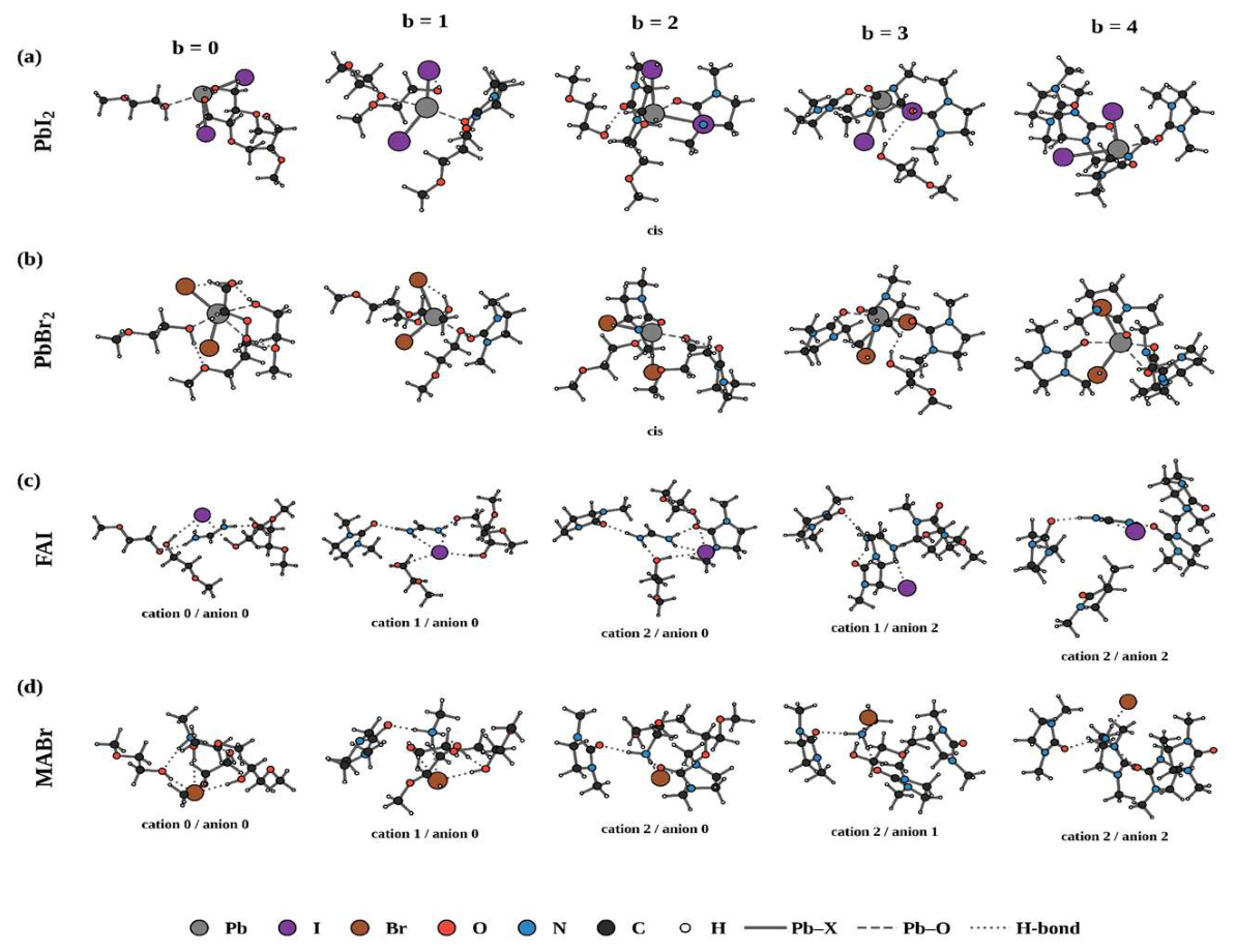
Figure 2.
Free energies ΔGb (Equation (3)) of the stepwise exchange of 2Me for DMI in the first solvation shell as a function of the number of coordinated DMI molecules, b: (a) PbI₂, (b) PbBr₂, (c) FAI and (d) MABr. For PbX₂ the cis and trans isomers at b = 2 are shown with different markers; for FAI and MABr the number of DMI molecules at the anion site (a = 0, 1, 2) is shown with different markers. The line connects the Boltzmann-effective values of the isomers at the same b. Negative values indicate that DMI coordination is thermodynamically favored. T = 298.15 K.
Figure 2.
Free energies ΔGb (Equation (3)) of the stepwise exchange of 2Me for DMI in the first solvation shell as a function of the number of coordinated DMI molecules, b: (a) PbI₂, (b) PbBr₂, (c) FAI and (d) MABr. For PbX₂ the cis and trans isomers at b = 2 are shown with different markers; for FAI and MABr the number of DMI molecules at the anion site (a = 0, 1, 2) is shown with different markers. The line connects the Boltzmann-effective values of the isomers at the same b. Negative values indicate that DMI coordination is thermodynamically favored. T = 298.15 K.
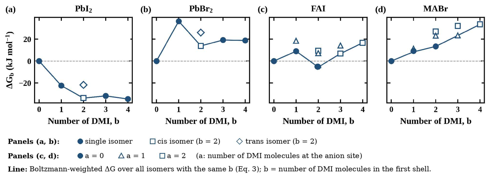
Figure 3.
Relative saturation solubility Ssat(φ)/Ssat(0) of the precursors as a function of the DMI volume fraction φ, calculated with Equation (5) and the mass balance: (a) PbI₂, (b) PbBr₂, (c) FAI and (d) MABr. The solid line is calculated with the computed ΔGb; the shaded band is the range obtained by shifting ΔGb by ±4 kJ mol⁻¹ per DMI molecule. The upper axis gives the 2Me:DMI volume ratio.
Figure 3.
Relative saturation solubility Ssat(φ)/Ssat(0) of the precursors as a function of the DMI volume fraction φ, calculated with Equation (5) and the mass balance: (a) PbI₂, (b) PbBr₂, (c) FAI and (d) MABr. The solid line is calculated with the computed ΔGb; the shaded band is the range obtained by shifting ΔGb by ±4 kJ mol⁻¹ per DMI molecule. The upper axis gives the 2Me:DMI volume ratio.
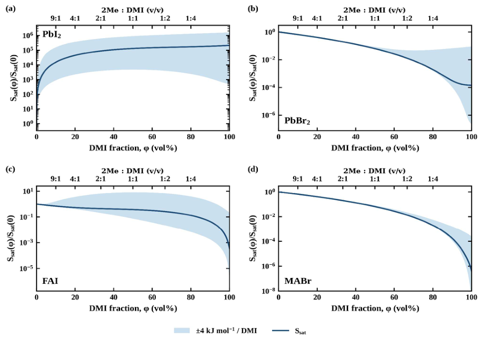
Figure 4.
Full-exchange free energy per DMI molecule, ΔGn/n (n = 4); error bars are ±4 kJ mol⁻¹. A negative value indicates that DMI is preferentially solvating, a positive value that 2Me is.
Figure 4.
Full-exchange free energy per DMI molecule, ΔGn/n (n = 4); error bars are ±4 kJ mol⁻¹. A negative value indicates that DMI is preferentially solvating, a positive value that 2Me is.
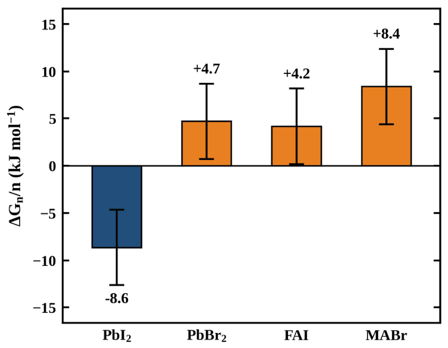
Figure 5.
Photographs of perovskite precursor solutions in different solvents: (a) DMF, (b) DMSO, (c) DMF:DMSO, (d) NMP, (e) DMF:NMP (conventional formulations); (f) 2Me, (g) DMI, (h) 2Me:DMI, (i) 2Me:NMP (alternative and green formulations).
Figure 5.
Photographs of perovskite precursor solutions in different solvents: (a) DMF, (b) DMSO, (c) DMF:DMSO, (d) NMP, (e) DMF:NMP (conventional formulations); (f) 2Me, (g) DMI, (h) 2Me:DMI, (i) 2Me:NMP (alternative and green formulations).
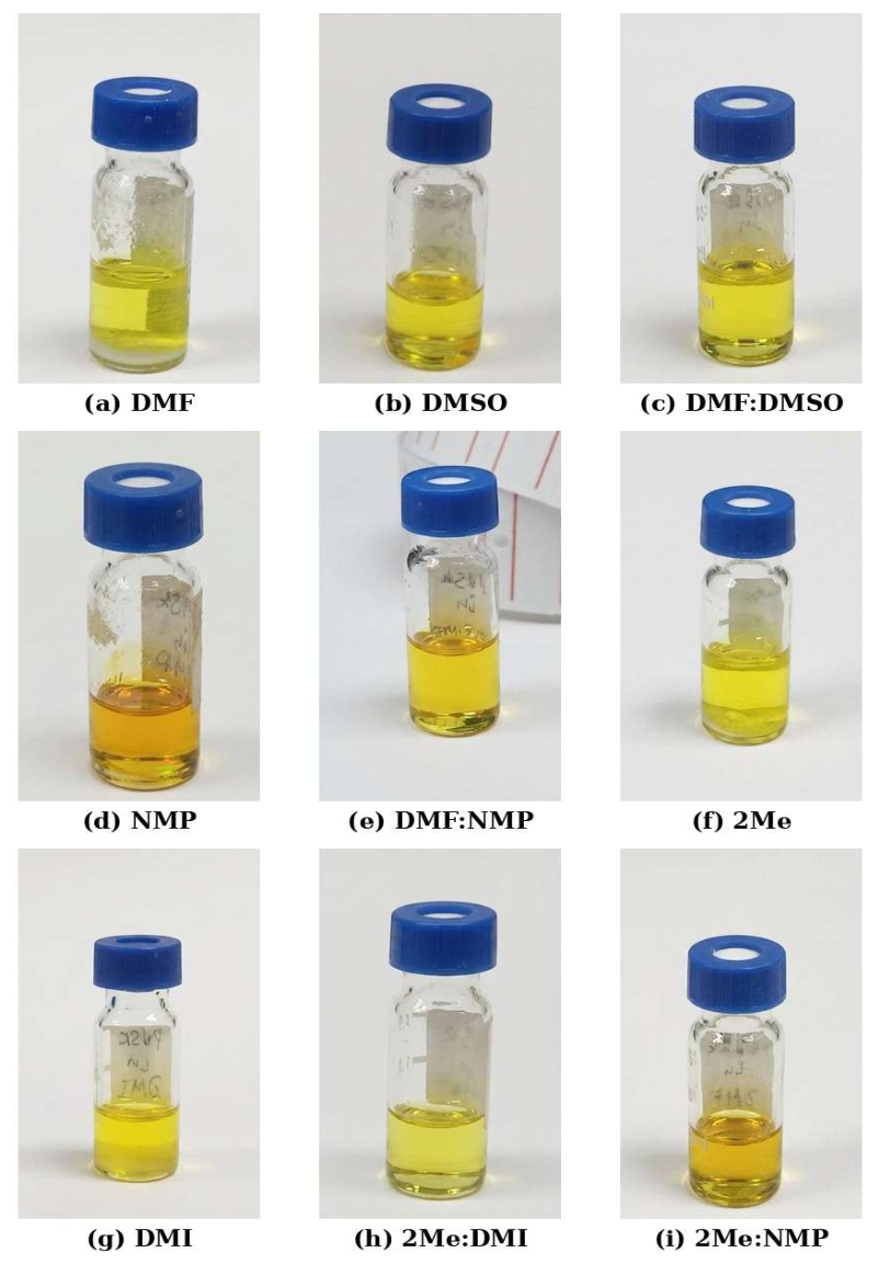
Figure 6.
FTIR spectra of the 2Me:DMI binary solvent and of solutions containing the precursors (MABr, FAI, PbI₂ and PbBr₂). The vertical lines mark the C–H stretching (3000–2780 cm⁻¹) and C=O stretching (1750–1630 cm⁻¹) regions. The spectra are offset vertically.
Figure 6.
FTIR spectra of the 2Me:DMI binary solvent and of solutions containing the precursors (MABr, FAI, PbI₂ and PbBr₂). The vertical lines mark the C–H stretching (3000–2780 cm⁻¹) and C=O stretching (1750–1630 cm⁻¹) regions. The spectra are offset vertically.
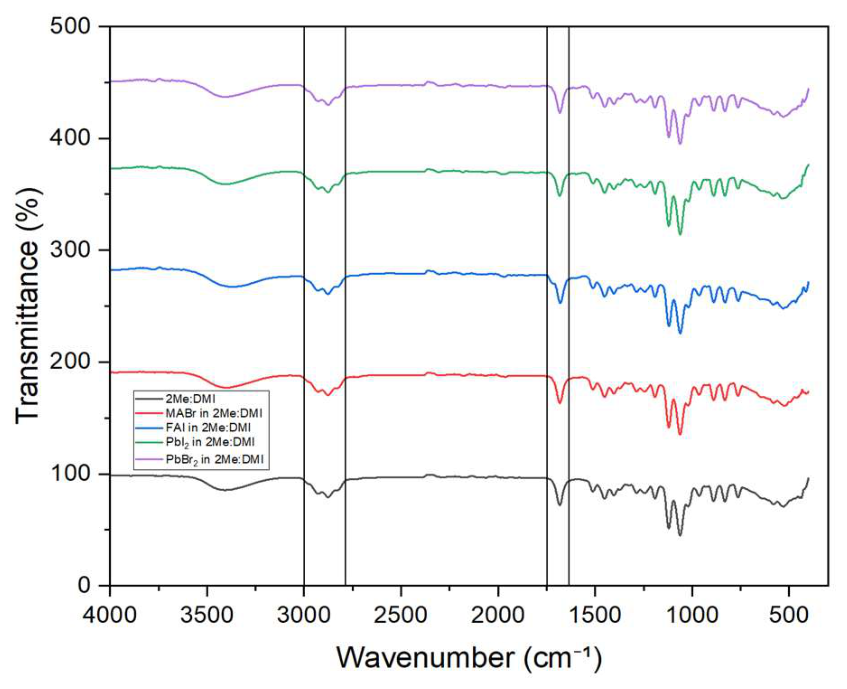
Figure 7.
UV–vis absorption spectra of perovskite (PVSK) films prepared from the 2Me:DMI and DMF:DMSO inks. The dashed line marks the absorption onset at 776 nm.
Figure 7.
UV–vis absorption spectra of perovskite (PVSK) films prepared from the 2Me:DMI and DMF:DMSO inks. The dashed line marks the absorption onset at 776 nm.
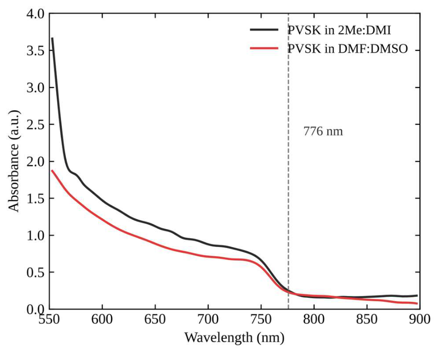
Figure 8.
Contact angle of 2Me/DMI mixtures on PTAA as a function of the DMI volume fraction. The shaded band marks the 10–20 vol% DMI range that the calculations identify as suitable for dissolving all four precursors (Figure 3).
Figure 8.
Contact angle of 2Me/DMI mixtures on PTAA as a function of the DMI volume fraction. The shaded band marks the 10–20 vol% DMI range that the calculations identify as suitable for dissolving all four precursors (Figure 3).
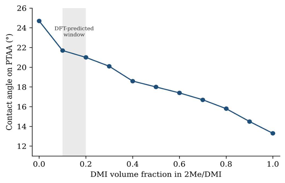
Figure 9.
Top-view SEM images (secondary electrons, 8000×) of perovskite films cast from (a) DMF:DMSO and (b) 2Me:DMI on PTAA. Scale bars, 2 μm. The images were denoised (non-local-means filter) and their contrast was stretched; no other processing was applied.
Figure 9.
Top-view SEM images (secondary electrons, 8000×) of perovskite films cast from (a) DMF:DMSO and (b) 2Me:DMI on PTAA. Scale bars, 2 μm. The images were denoised (non-local-means filter) and their contrast was stretched; no other processing was applied.
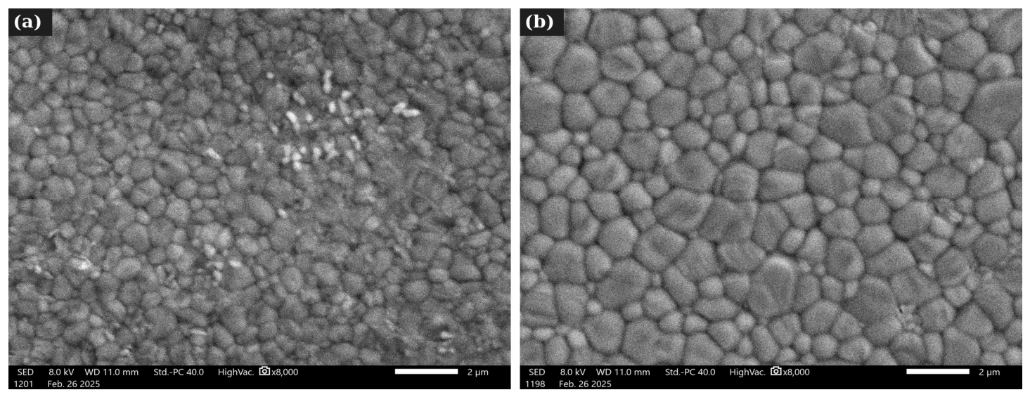

Table 1.
Properties of 2Me and DMI used in the model (25 °C).
| Property | 2Me | DMI |
|---|---|---|
| Dielectric constant, ε | 16.9 | 37.6 |
| Density, g mL⁻¹ | 0.965 | 1.056 |
| Molar mass, g mol⁻¹ | 76.09 | 114.15 |
| Pure-liquid concentration, mol L⁻¹ | 12.68 | 9.25 |
| Boiling point, °C | 124 | 225 |
| Donor atom | hydroxyl O | carbonyl O |
| H-bond donor | yes (O–H) | no |
Disclaimer/Publisher’s Note: The statements, opinions and data contained in all publications are solely those of the individual author(s) and contributor(s) and not of MDPI and/or the editor(s). MDPI and/or the editor(s) disclaim responsibility for any injury to people or property resulting from any ideas, methods, instructions or products referred to in the content. |
© 2026 by the authors. Licensee MDPI, Basel, Switzerland. This article is an open access article distributed under the terms and conditions of the Creative Commons Attribution (CC BY) license (http://creativecommons.org/licenses/by/4.0/).
Copyright: This open access article is published under a Creative Commons CC BY 4.0 license, which permit the free download, distribution, and reuse, provided that the author and preprint are cited in any reuse.