

Submitted:
19 October 2026
Posted:
20 October 2026
You are already at the latest version
Abstract
The sustained increase in energy density in lithium-ion battery modules requires robust thermal management strategies to mitigate excessive heat accumulation. In this study, a directional thermal decoupling strategy is systematically evaluated in an 8S2P module comprising 60 Ah pouch cells by implementing a three-dimensional coupled electrochemical–thermal conjugate framework. Under continuous 2C discharge at an elevated ambient temperature, five inter-cell insulation sheets and five lateral thermal interface materials coupled to serpentine cold plates are comparatively evaluated. Nanoporous aerogel-like barriers limit heat conduction along the stacking direction but significantly hinder lateral diffusion toward the module edges, raising the maximum temperature to between 332.5 and 333.7 K and the temperature difference to 13.5 K, while yielding lower heat rejection rates ranging from 169.8 to 171.7 W. Conversely, anisotropic graphite sheets enhance in-plane heat spreading, reduce maximum volumetric heat generation, decrease maximum temperature to 322.3K, and raise Q˙rej to 187.0W. At the lateral interface, a conformable AlN/PDMS composite minimizes conductive resistance, yielding an optimal heat rejection rate of 188.94 W and maintaining maximum temperature at 321.97K. These findings establish quantitative design criteria to effectively balance inter-cell thermal isolation with active heat evacuation under severe nominal operating regimes.
Keywords:
lithium-ion battery
; thermal management
; insulation sheet
; thermal interface material
1. Introduction
The irreversible transition toward sustainable energy systems and the rapid decarbonization of transport have positioned lithium-ion batteries (LIBs) as the leading energy-storage technology in electric vehicles (EVs), thanks to their high energy density, long service life, and low self-discharge rate [2,3,11,41,43]. However, continued progress in developing high-capacity cells (180 Ah and above) to meet growing range demands significantly increases the risks associated with catastrophic failures triggered by thermal, mechanical, or electrical abuse [2,9,40,42]. Thermal runaway (TR) is the most severe safety risk in lithium batteries: a highly exothermic event characterized by a rapid rise in temperature and the release of flammable gases [1,4,41,42]. If not contained in time, the heat generated by a faulty cell is transferred to neighboring cells via conduction, convection, and radiation, leading to a chain reaction (thermal runaway propagation, TRP) [10,13,43,44]. In automotive packs, this chain reaction can release more than 923.5 MJ, equivalent to 198.6 kg of TNT [13]. Consequently, the design of next-generation Battery Thermal Management Systems (BTMSs)—leveraging advanced TIMs to maximize heat dissipation toward cold plates and inter-cell insulation barriers to mitigate TRP—is imperative to prevent operational overheating and ensure the long-term safety of electric mobility [7,14,15,39,44].
The large-scale adoption of LIBs in electric vehicles has driven rapid progress in the design of passive and active mitigation strategies at the module level. To limit thermal propagation between cells, the scientific literature has devoted considerable effort to developing passive insulation barriers [16,17,18,40,43]. Traditionally, static materials such as mica plates have been used due to their high thermal stability; however, they have significant limitations in terms of energy density and exhibit a limited ability to mitigate localized heat buildup, which in high-capacity modules typically only delays, but does not prevent, TRP [9,11,43]. To address these limitations, silica nanocomposite aerogels have been developed, characterized by extremely low thermal conductivities ( to ) and high porosity [5,6,40,44]. A representative example is silica aerogels reinforced with glass or ceramic fibers (such as the composite), which have been shown to preserve their structural integrity up to 1100 °C without collapsing due to sintering, while keeping the temperature of adjacent cells below 94° [6]. Likewise, integrating aerogels with nanocellulose meshes featuring a biomimetic tracheal structure has made it possible to tune the radial thermal conductivity to and to double the compressive modulus, reaching [7]. Similarly, alumina doping—which promotes the formation of stable Al-O-Si bonds in composite aerogels produced at atmospheric pressure—has demonstrated an excellent ability to prevent structural collapse at temperatures above [20]. However, purely static insulators face the physical constraint of being unable to absorb the intense transient heat flux generated during TR, which leads to heat buildup that ultimately compromises the affected cell [10,21,42,43]. As an alternative strategy, phase-change materials (PCMs) based on polyethylene glycol (PEG) or paraffins have been incorporated, which can absorb thermal energy via latent heat of fusion [22,23,39]. Nevertheless, the intrinsic flammability and the potential for leakage of these organic PCMs restrict their application under extreme conditions [20,22,39,44]. To address this issue, recent studies have focused on hybrid systems based on polymeric gels of hydrated salts or composites featuring a silicone elastomer matrix and hollow glass microspheres. These materials leverage a dehydration enthalpy exceeding to absorb heat endothermically at , adaptively reducing the thermal conductivity from 0.52 to 0.056 and thereby providing an intelligent “thermal switch” effect capable of preventing propagation with thicknesses as small as 2 mm [20,24,39,44].
Simultaneously, advances in three-dimensional numerical modeling tools (CFD and FEM) have made it possible to deepen the phenomenological characterization and the kinetics of TRP at both the module and pack scales [17,25,40,43]. Computational fluid dynamics models have enabled the simulation of complex gas ejection and combustion phenomena, such as jet-flame-driven fires in double-layer packs for heavy-duty vehicles, quantifying radiative and convective heat transfer and establishing critical thermal resistances equivalent to thick mica sheets [4]. Likewise, large-scale numerical simulations based on stochastic and distributed approaches show that both the number of cells and their spatial arrangement influence the thermal runaway propagation speed in a nonlinear manner [25,41]. Under normal operating conditions, multiphysics modeling has been identified as a key element for anticipating the spatial temperature distribution and designing the cell layout to maximize turbulence and reduce the pack temperature difference below under a 4C charge rate [4]. It is worth highlighting that these coupled numerical models have made it possible to link macroscopic thermal management with microscopic electrochemical kinetics, showing that precise thermal control at the graphite anode stabilizes the solid electrolyte interphase (SEI) layer and suppresses the formation of lithium dendrites responsible for internal short circuits [17,26,43].
From a systems-integration perspective, studies combining experimental and numerical approaches have shown that active liquid cooling (ALC) is highly effective at removing the heat generated during module operation [17,25,39,44]. However, its thermal performance is strongly constrained by air microcavities trapped at the physical interface between the cell bases and the aluminum cold plate, which cause temperature discontinuities and a high thermal contact resistance [26,45]. To alleviate this bottleneck, TIMs and structural thermally conductive adhesives are used, typically formulated with flexible polymers such as PDMS and loaded with alumina nanoparticles (), graphene, or boron nitride, with the goal of maximizing both through-thickness and in-plane conductivity [27,28,45]. Based on anisotropic heat-transfer analysis and validated aging simulations, it has been found that the TIM through-thickness conductivity is directly linked to reducing the maximum temperature (), while the in-plane conductivity markedly improves the module’s thermal uniformity, reducing temperature discontinuities by up to 90% and directly extending the battery state of health (SoH) after 1000 cycles [26,45]. Likewise, the numerical-experimental integration of liquid cooling plates optimized with aluminum-foam structural casings (AFS) makes it possible to achieve an optimal trade-off between the module’s structural strength and active heat dissipation, reducing pack mass by up to 16.8% [21].
To overcome state-of-the-art limitations, the central contribution of this article is the development of a three-dimensional, transient numerical modeling framework that enables a coupled and systematic evaluation of the behavior of different TIMs and inter-cell insulation barriers, with thicknesses ranging from , in high-capacity lithium battery modules. By incorporating an active cooling system based on cold plates operating under extreme ambient conditions, the model examines the synergistic interaction between anisotropic TIM conductivities and coolant flow parameters. By incorporating benchmark barrier materials previously reported in the literature for passive thermal runaway mitigation, this work investigates critical operational metrics, including spatiotemporal temperature profiles ( and ), interfacial conductive impedance (), module heat generation rate (), and heat rejection by the liquid cooling plates (). On this basis, an optimal configuration is identified that ensures a homogeneous thermal distribution and keeps temperature peaks within nominal safety margins, thereby providing thermophysical design guidelines for high-efficiency automotive packs.
2. Numerical Methodology
2.1. Geometric Model
In this research, a pouch-type electrochemical cell with a nominal capacity of 60 Ah [29], manufactured by Leclanché Energy Solutions, is used. The thermophysical and electrochemical properties of this cell are detailed in Table 1. Based on this basic unit, a battery module consisting of 16 cells electrically connected in an 8S2P configuration was designed, achieving a total nominal capacity of 120 Ah and overall dimensions of , as shown in Figure 1. Regarding the thermal configuration, directional thermal decoupling was applied: along the stacking direction (the Z axis, perpendicular to the largest-area faces in the plane), thermal insulation barriers with a thickness of were added between adjacent cells (Figure 1) to limit transverse conduction and provide the inter-cell thermal resistance recommended in the literature. On the other hand, on the lateral faces of the module (the plane), the assembly was coupled to aluminum cooling plates with serpentine channels (Figure 1, Figure 1) through a continuous TIM layer with a thickness of . The main function of this component is to enhance heat transfer to the coolant by reducing the interfacial thermal impedance (), assessing either isotropic or anisotropic thermal behavior depending on the material used.
2.2. Governing Equations
The transient thermal behavior of lithium-ion cells is described by the three-dimensional energy conservation equation in the solid domain of the cell [29,31]:
where , , and represent the cell density, specific heat capacity, and local temperature, respectively [29]. The parameter corresponds to the orthotropic thermal-conductivity tensor, which explicitly incorporates the in-plane components and the through-thickness component of the material, thus reflecting the directional nature of heat transfer in anisotropic media [30]. Under standard operating conditions in discharge mode and at high C-rates, the total volumetric heat-generation rate is defined as the sum of the contributions associated with electrochemical reactions, reversible entropic heating, and the ohmic Joule effect, while source terms due to internal short circuits and thermal abuse conditions are neglected [29,30]:
The spatial distribution of the electric potentials in the current collectors of the positive and negative electrodes is quantitatively characterized by the corresponding Poisson equations [31,32]:
where and represent the electrical conductivities of the positive and negative electrodes, respectively, and denote the phase potentials associated with each of these electrodes, and j corresponds to the volumetric current density transferred in the system [32].
In order to accurately reproduce the non-uniform distribution of current density and heat-generation source terms, the Multi-Scale Multi-Domain (MSMD) framework is implemented, coupled with the semi-empirical Newman–Tiedemann–Gu–Kim (NTGK) submodel [30,32]. Within the NTGK formulation, the volumetric current density j is defined as in [29]:
where a is the specific active surface area of the electrochemical material, U denotes the open-circuit potential, and Y corresponds to the kinetic parameter associated with the reaction rate [29]. Both U and Y exhibit a dynamic dependence on the cell depth of discharge (DOD) and the local temperature , and are modeled using the following empirical polynomial expressions [29,31]:
where and are the polynomial coefficients determined specifically for the 60 Ah pouch cell [29]; denotes the operating reference temperature, while and correspond to the empirical constants of the NTGK model [29,30]. The local depth-of-discharge state is obtained by time integration of the current density [29]:
where Vol is the active volume of the cell and corresponds to its nominal capacity () [29]. The electrochemical heat generation rate is determined as [29]:
Subsequently, the heat generated in the cells is transferred by conduction through the intercellular insulation barriers, the lateral TIM layers, and the aluminum cooling plates [29,33]. Consequently, the energy conservation equation for these passive solid domains is expressed as [30]:
where the subscript i denotes the corresponding solid component [29]. In the case of structured or anisotropic materials, the thermal conductivity tensor is explicitly decomposed along the Cartesian coordinates, where the in-plane components parallel to the sheet are defined by and , while the through-plane component perpendicular to the interface corresponds to [29].
At solid–solid interfaces (cell–TIM and TIM–cold plate), thermal coupling was modeled numerically using coupled wall boundary conditions, enforcing strict continuity of conductive heat flux and local temperature between adjacent domains. Accordingly, the thermal impedance of the interface is directly governed by three-dimensional conduction across the physical TIM thickness (). This formulation reasonably assumes intimate microscopic surface wetting facilitated by typical module assembly pre-compression, thereby avoiding the introduction of empirical thin-wall thermal resistance approximations.
On the other hand, to dissipate the heat transferred to the cooling plates, the coolant flowing through the serpentine-channel configuration is modeled as an incompressible, single-phase fluid with constant thermophysical properties [30,31]. Accordingly, hydrodynamic and thermal transport in the fluid domain is described by solving the three-dimensional Reynolds-averaged Navier–Stokes (RANS) equations, coupled with the energy conservation equation [31]:
where , P, and denote, respectively, the velocity vector, the static pressure, and the coolant temperature [31]. Likewise, the quantities , , , , and represent the density, dynamic viscosity, eddy turbulent viscosity, specific heat capacity, and thermal conductivity of the working fluid [29,31].
2.3. Boundary Conditions
To ensure numerical fidelity and an adequate physical representation of the thermohydraulic and electrochemical behavior of the cooling system, boundary and initial conditions were defined in the computational domain, integrating the NTGK electrochemical model with transient fluid transport. The operating, thermal, and transport conditions considered in the simulation are detailed below:
- The NTGK model is used to define the battery heat source, assuming a 2C discharge rate.
- The exposed surfaces of the battery module are characterized by a natural convection coefficient of 5 W/(m2·K) under an ambient temperature of 313.15 K.
- The values of the variables and are experimentally obtained constants, and the fitting parameters and are given in Table 2.
- UDS-0 refers to the electrical conductivity of the cell anode, and UDS-1 refers to the electrical conductivity of the cell cathode; these are specified in the material electrical conductivity column.
- The inlet velocity is , corresponding to a Reynolds number based on the serpentine hydraulic diameter (). Although this value lies in the early transition regime for straight pipes, the repeated bends in the plate induce centrifugal instabilities and pairs of secondary vortices (Dean effect), promoting turbulent mixing at . This justifies the selection of the Realizable turbulence model coupled with Enhanced Wall Treatment (EWT) [31]. The fluid inlet temperature was set to , and the outlet boundary condition was set to zero gauge pressure ().
2.4. Model Formulation and Solution Procedure
Three-dimensional multiphysics numerical simulations were carried out using the commercial computational fluid dynamics platform ANSYS Fluent, based on the finite volume method. To adequately represent hydrodynamic phenomena in the cooling channels, the energy equation was enabled, and the Realizable k- turbulence model was employed, coupled with Enhanced Wall Treatment (EWT). Boundary-layer discretization at the fluid-channel walls was set using prismatic refinement layers with a first-cell height of () and a growth rate of 0.5. This resolution places the dimensionless wall distance of the first node in the range between 3.5 and 7.0, allowing the EWT formulation to apply continuous interpolation functions that rigorously resolve the viscous and buffer sublayers without overestimating diffusive transport or friction associated with standard wall functions in narrow ducts [31].
Electrochemical–thermal coupling was addressed using a multi-scale, multi-domain (MSMD) approach with the semi-empirical NTGK submodel, solving the transport equations associated with the electric potentials ( and ) and including both heat generation from electrochemical reactions and ohmic dissipation due to the Joule effect in the active regions and in the terminals/current collectors (tabs/busbars). Pressure–velocity coupling was performed using the Coupled algorithm. Spatial discretization of gradients used the Cell-Based Least Squares scheme (Least Squares Cell-Based), including Warped-Face Gradient Correction. Pressure was discretized with a Second Order scheme (Second Order). The momentum equations, turbulent kinetic energy (k), turbulent dissipation rate (), thermal energy, and electrochemical potentials (uds−0 and uds−1) were solved using Second Order upwind formulations (Second Order Upwind). Time integration of the transient problem was implemented using a Second Order implicit scheme (Second Order Implicit). Finally, the absolute convergence criteria per time step were set to for the continuity equation, the velocity components (), k, and , and to for thermal energy and the electric potentials.
2.5. Grid Independence and Model Validation
To assess numerical accuracy and optimize computational cost, a grid-independence study was performed for the 16-cell battery module, thereby ensuring the reliability of the results and improved computational efficiency. The computational domain was discretized using a poly-hexcore mesh, and four refinement levels were analyzed: 4,703,830 (Mesh 1), 7,760,979 (Mesh 2), 9,973,897 (Mesh 3), and 11,938,270 (Mesh 4) elements. The performance metrics considered were the maximum temperature, the average module temperature (), and the coolant pressure drop () across the cooling plate, assuming a 2C discharge rate, an ambient temperature of 313.15 K, and a fluid inlet velocity of 1.5 m/s. The variation of these quantities with the number of elements is shown in Figure 2. As shown in the figure, and quickly stabilize starting from Mesh 2, with an almost negligible discrepancy between Mesh 3 and Mesh 4 of only 0.017 K and 0.005 K, respectively. Regarding the pressure drop , it increases progressively as the mesh is refined until reaching a plateau beyond 9.97 million elements. The relative difference in between Mesh 3 (63.68 kPa) and Mesh 4 (64.53 kPa) is only 0.85 kPa (1.33%), remaining well below the established tolerance threshold of 5% [46]. Since the variations in the thermal and hydrodynamic metrics between Mesh 3 and Mesh 4 are negligible, Mesh 3 was selected for subsequent numerical analyzes, achieving a suitable trade-off between physical fidelity and computational cost.
To verify the accuracy and reliability of the coupled electrochemical–thermal (MSMD-NTGK) model, a numerical validation was performed by comparing the obtained results with the experimental data reported by Dileep et al. [29]. The test was conducted for a single 60 Ah pouch cell subjected to a 2C discharge regime, under natural convection and an initial ambient temperature of 315.15 K, without active liquid cooling. The time evolution of the numerically obtained average surface temperature of the cell and its corresponding comparison with the experimental measurements is shown in Figure 3. As illustrated in the figure, the computational model reproduces the transient heating dynamics throughout the entire discharge cycle, achieving a mean absolute error (MAE) of 1.62 K between the experimental and numerical curves. This close agreement confirms the model’s ability to predict heat generation and dissipation in the cell with high accuracy, establishing the validity of the numerical framework for extension to the thermal analysis of the full 8S2P module.
3. Results and Discussion
In this section, the thermohydraulic response of an 8S2P battery module under continuous 2C discharge in a harsh environment is analyzed through three-dimensional multiphysics numerical simulations based on electrochemical–thermal multidomain formulations [32]. The module follows a directional thermal-decoupling architecture: the lateral faces () are coupled to aluminum cold plates through a continuous TIM layer of controlled thickness (), while serpentine channels provide forced convection with water at an inlet velocity of and an inlet temperature of [30,31]. To isolate and quantify the dominant heat-transfer mechanisms, five materials reported as inter-cell thermal barriers (insulation sheets, IS) and five lateral TIM formulations are systematically compared, while keeping the hydrodynamic and thermal boundary conditions constant [29,33]. Since the study is restricted to nominal operation, thermal abuse scenarios and exothermic failure events are not modeled; therefore, any implications regarding thermal runaway propagation are discussed solely in terms of thermal coupling/decoupling metrics reported in the literature.
3.1. Influence of Intercell Thermal Barriers (IS) on Spatial Distribution and Terminal Thermal Performance
Figure 4 shows the spatiotemporal evolution of the thermal field of the 8S2P module under continuous 2C discharge for five inter-cell barriers: (a) silica aerogel, (b) , (c) Nano SiAG felt, (d) C1.0-PT aerogel, and (e) anisotropic graphite sheet. In the first third of the transient (), heat dissipation is dominated by irreversible losses associated with internal ohmic polarization [32]. Considering the effective volumetric thermal inertia of the active components, characterized by () [3], is obtained for all configurations.
However, once the depth of discharge exceeds 50% (), increased electrochemical overpotential heating and reversible enthalpic effects markedly raise the volumetric heat generation rate [32]. In structured configurations with insulating materials (Figure 4a–Figure 4d), the low through-plane thermal conductivity () imposes a dominant conductive resistance along the stack () [2,6]. This limits inter-cell thermal diffusion in Z, so heat is redistributed predominantly by two-dimensional conduction in the plane toward the cooled walls () [29]. The long diffusion distance promotes heat accumulation in the upper central region and, toward the end of the cycle (), a quasi-steady regime from 332.5 to 333.7 K is reached. Although high through-plane resistance is associated in the literature with weaker inter-cell thermal coupling [9,11], thermal runaway events are not evaluated in this work; under nominal conditions, the dominant effect is an operational penalty due to larger local thermal gradients.
The final characterization of the module at the end of discharge () is shown in Figure 5, comparing the local maximum temperature and the mean temperature . As illustrated in Figure 5, the nanoporous insulation sheets (conventional silica aerogel, , Nano SiAG felt, and C1.0-PT aerogel) exhibit nearly identical terminal temperatures: from 332.5 to 333.7 K and from 319.1 to 319.9 K, consistent with their comparable through-plane thermal resistances [15,18]. Consequently, the module volumetric gradient reaches of 13.5 K and the global temperature span is of 30.7 K, substantially exceeding the standard automotive uniformity threshold (). Among the evaluated porous materials, C1.0-PT aerogel demonstrated slightly better thermal behavior ( and ), which can be attributed to its marginally higher thermal diffusivity .
The anisotropic graphite sheet reduces the thermal indicators at the end of discharge (; ) due to its high conductive anisotropy ( versus ), which increases in-plane thermal diffusion and promotes heat spreading toward the lateral heat sinks [28,29]. Under these conditions, thermal non-uniformity is limited to and is maintained, a threshold associated with mitigating accelerated aging [19].
Figure 6 shows the three-dimensional distribution of the total heat source () computed with the coupled MSMD-NTGK framework at the end of a 2C discharge. For the cases with nanoporous barriers (Figure 6a–d), heat retention in the core increases the local volumetric power up to , due to the strong thermal dependence of and the increase in electrochemical overpotential. In contrast, anisotropic graphite sheets (Figure 6e) reduce thermal polarization by conducting heat toward the lateral cold plates, keeping the maximum below and highlighting the impact of thermal coupling on net heat generation.
Figure 7 compares the module heat rejection rate through the cooling plate at the end of the 2C discharge, . The anisotropic graphite sheet shows the best performance (), 10.1% higher than conventional aerogel (), due to its high in-plane conductivity, which reduces conductive resistance and guides heat toward the cold plates. In contrast, the other options (, Nano SiAG, and C1.0-PT) show similar, lower values of 171 W due to their low limits transporting along the Z-axis, which increases the heat retained in the core.
However, the exclusive use of graphite sheets introduces a thermal trade-off: their residual through-plane conductivity, which is 1-2 orders of magnitude higher than that of conventional aerogels, reduces inter-cell thermal decoupling and increases the fraction of conductive heat transfer between cells before lateral cooling absorbs the excess load [29,33]. Consequently, directional-decoupling architectures are required that integrate ultra-low- barriers and high-diffusivity lateral pathways for active heat dissipation [1,24].
3.2. Influence of Lateral Thermal Interface Material (TIM) on Heat Dissipation to Cold Plates
Heat dissipation toward the lateral cold plates is governed by the interfacial thermal impedance of the TIM in the plane, which is designed to suppress air micro-voids without significantly increasing the parasitic conductive resistance () [26,27]. Figure 8 presents the spatiotemporal evolution of the temperature field in the 8S2P module for five lateral TIMs: (a) Thermal pad, (b) Thermal silicone gel, (c) Mica sheet, (d) VA-3D-BN/Polymer, and (e) AlN/PDMS. Figure 8 shows that conformable, high-conductivity lateral TIMs reshape the thermal field relative to decoupled configurations by intensifying lateral heat extraction and suppressing heat accumulation in the winding; thus, throughout the transient.
Figure 9 quantifies thermal performance at the end of discharge () and shows that AlN/PDMS achieves the lowest () and (). This result is attributed to a percolating AlN network in the PDMS matrix, which increases k and and reduces the contact thermal resistance at the cell-cold-plate interface, thereby enhancing heat extraction to the coolant.
These results confirm that minimizing interfacial impedance governs heat extraction toward the cold plates under nominal operating conditions.
In contrast, the mica sheet and the VA-3D BN/Polymer composite exhibit the least favorable temperatures in the group, reaching values of and , together with values of and , respectively. In the case of mica, its intrinsic mechanical rigidity and limited surface deformation capability prevent complete microscopic wetting of the aluminum wall’s roughness, inducing additional contact resistance that slows transient heat flow. Meanwhile, although the VA-3D BN/Polymer composite features high anisotropic conductivity engineered along a preferred direction, slight misalignment between the orientation axis of the boron nitride chains and the normal heat-flow vector toward the cold plate reduces the effective through-thickness conductivity, increases interfacial thermal inertia, and retains a larger fraction of energy within the module.
Conversely, the conventional thermal pad and silicone gel display essentially equivalent thermal performance, yielding 4 of 322.3 K and of 313.2 K. Although both formulations exhibit moderate thermal conductivities (k from 1.5 to 3.0 ), their low elastic modulus and viscoelastic conformability ensure intimate contact under mechanical pre-compression, effectively eliminating insulating air micro-voids without introducing excessive thickness that would otherwise increase bulk conductive resistance ().
From the standpoint of safe-operation criteria and electrochemical durability, all of the evaluated TIMs succeed in suppressing critical overheating, keeping the cells within the range of 322.0 to 323.6 K ( °C), a value fully compatible with the preventive threshold against accelerated electrolyte degradation and the uncontrolled growth of the SEI layer. Nevertheless, the volumetric thermal gradient between the hot core and the module average stabilizes at from 9.1 to 9.2 K. Although this gradient still exceeds the stringent isothermal-uniformity target () due to the physical length of two-dimensional transport within large-format pouch cells (60 Ah), it represents an improvement of more than 30% compared with conventional architectures that lack a continuous lateral heat-dissipation pathway.
Figure 10 shows the 3D distribution of the volumetric heat generation rate () in the 8S2P module at the end of a 2C discharge for different lateral TIM formulations. In all cases, a continuous dissipation pathway on the lateral faces reduces thermal peaks, keeping the maximum volumetric power below . Nevertheless, local heterogeneities associated with interfacial thermal impedance are observed. With lower effective thermal diffusivity and/or higher conductive resistance (Figure 10a–d), transient heat accumulation near the electrode periphery moderately increases the electrochemical polarization predicted by the NTGK model. In contrast, the AlN/PDMS composite (Figure 10e) promotes a more uniform diffusive transfer toward the aluminum plate, achieving the highest spatial uniformity of and showing that a low-impedance interface mitigates the positive feedback between internal temperature and heat generation.
To assess the effect of the interfacial layer on convective dissipation, Figure 11 presents the net heat transfer rate to the coolant at the end of the 2C discharge. The evacuated power ranges from to depending on the TIM applied to the walls. AlN/PDMS achieves the highest (), 8.55 W (+4.74%) higher than VA-3D-BN/Polymer. This is explained by its high thermal conductivity () and thermal diffusivity (), which decrease the conductive resistance (), mitigate hot spots, and reduce the module maximum temperature ().
On the other hand, the conventional thermal pad and the silicone gel exhibit comparable thermodynamic behavior, with heat removal rates of and , respectively, which suggests adequate continuity of the heat flux under mechanical compression. In contrast, the higher intrinsic stiffness of the mica sheet reduces the dissipation capacity to , while the vertically aligned VA-3D-BN/Polymer composite exhibited the lowest heat removal rate in the group (). Although this composite features high through-plane conductivity, its relatively low in-plane thermal conductivity hinders tangential heat spreading toward the active serpentine channels, causing localized heat retention between channel ribs and leading to a higher maximum temperature ().
The observed sensitivity in the heat rejection rate and temperature peaks highlights the need for joint optimization of the lateral interface and the inter-cell barriers within the module’s overall energy balance. In terms of thermal trade-offs, the proposed configuration provides a low-thermal-impedance lateral dissipation pathway without relying on interleaved metal plates or the extended pathways characteristic of bottom cooling, which supports thermal control during continuous 2C discharge with only a marginal impact on pack mass and volume. However, although increasing inter-cell through-plane conductive resistance (Z) is a widely used strategy to enhance passive safety, the effectiveness of this architecture in confining or mitigating thermal runaway events and their propagation requires dedicated simulations and experiments under thermal-abuse conditions and cannot be conclusively inferred from the nominal operating regime evaluated in this work.
4. Conclusions
A coupled 3D multiphysics numerical framework (MSMD-NTGK) was developed to evaluate the thermohydraulic behavior and energy balance of an 8S2P module under harsh nominal conditions: , continuous 2C discharge, and liquid cooling at with . The study examines the thermophysical influence of inter-cell barriers and lateral thermal interface materials on three design metrics: Maximum temperature, temperature non-uniformity, and the thermal power rejected to the coolant. Because abuse scenarios were not included in the model, any conclusions about thermal runaway and how it spreads are outside the present scope and would require coupled simulations incorporating decomposition kinetics, along with targeted experimental validation. Based on the survey of five IS and five TIM, the following conclusions are reached:
- Nanoporous insulation sheet barriers (2.0 mm) with ultra-low through-plane thermal conductivities provide effective conductive decoupling along the stacking axis (Z), a property widely recognized for passive thermal runaway mitigation. However, under high-rate operational regimes, this confinement severely restricts transverse diffusion and forces two-dimensional in-plane heat evacuation, resulting in maximum temperatures from 332.5 to 333.7 K, a temperature difference of 13.5 K, and reduced heat rejection rates from 169.8 to 171.7 W.
- Anisotropic graphite sheets significantly mitigate hotspot accumulation (, ) and enhance heat removal to , driven by superior in-plane conductivity. Nevertheless, their moderate through-plane conductivity provides lower inter-cell thermal resistance compared with aerogels, confirming the need for hybrid barrier architectures that combine low normal conductivity with high-diffusivity lateral dissipation pathways.
- At the lateral module interface, the layer’s bulk thermal resistance largely controls transient heat extraction; therefore, high thermal conductivity should be combined with mechanical compliance. The AlN/PDMS elastomer reduced interfacial impedance and delivered the greatest heat rejection, of 188.94, with of 321.97 , demonstrating that interfacial rheology and the removal of micro-voids are key design drivers.
- Directional thermal decoupling—co-optimizing inter-cell barriers of low transversal conductivity with highly conformable lateral TIMs coupled to active liquid cooling—successfully resolves the operational trade-off between passive thermal protection and effective active heat removal for high-capacity lithium-ion battery modules.
Author Contributions
Conceptualization, L.E.M.-R. and J.F.I.-Y.; methodology, L.E.M.-R. and J.S.-A.; software, L.E.M.-R and J.F.I.-Y.; validation, L.E.M.-R., J.S.-A. and J.F.I.-Y.; formal analysis, L.E.M.-R., F.N.D.-L. and S.M.-G.; investigation, L.E.M.-R.; resources, J.F.I.-Y. and J.S.-A.; data curation, L.E.M.-R.; writing—original draft preparation, L.E.M.-R.; writing—review and editing, J.S.-A., J.F.I.-Y., F.N.D.-L. and S.M.-G.; visualization, L.E.M.-R. and F.N.D.-L.; supervision, J.F.I.-Y. and J.S.-A.; project administration, J.F.I.-Y.; funding acquisition, J.F.I.-Y. All authors have read and agreed to the published version of the manuscript.
Funding
This research received no external funding.
Data Availability Statement
The data presented in this study are available on request from the corresponding author, [Jean Fulbert Ituna-Yudonago], upon reasonable request.
Acknowledgments
Luis Enrique Marron-Ramirez acknowledges the financial support provided by the Secretaría de Ciencia, Humanidades, Tecnología e Innovación (SECIHTI) for his doctoral studies (CVU No. 987523). The authors also acknowledge the Tecnológico Nacional de México / Instituto Tecnológico de Pachuca for the financial support regarding the article processing charges (APC) for this publication.
Conflicts of Interest
The authors declare no conflict of interest.
Abbreviations
The following abbreviations are used in this manuscript:
| ALC | Active Liquid Cooling |
| BTMS | Battery Thermal Management System |
| CFD | Computational Fluid Dynamics |
| EWT | Enhanced Wall Treatment |
| FEM | Finite Element Method |
| IS | Insulation Sheet |
| MSMD | Multi-Scale Multi-Domain |
| NTGK | Newman–Tiedemann–Gu–Kim |
| PCM | Phase Change Material |
| PDMS | Polydimethylsiloxane |
| RANS | Reynolds-Averaged Navier–Stokes |
| SEI | Solid Electrolyte Interphase |
| SoH | State of Health |
| TIM | Thermal Interface Material |
| TR | Thermal Runaway |
| TRP | Thermal Runaway Propagation |
References
- Zhang, H.; Cao, S.; Zhang, H.; Ren, C.; Hu, R.; Chen, Z. Synergy of high-efficiency passive protective nanocomposite materials and active liquid cooling for suppressing thermal diffusion in lithium-ion power batteries. Appl. Energy Combust. Sci. 2025, 100433. [Google Scholar] [CrossRef]
- Mao, T.; Xiao, Y.; Cheng, X.; Pan, Y.; Li, L.; Yang, J.; Zhang, H.; Yang, H.; Zhao, J. Effects and mechanisms of thickness-tunable aerogel thermal barriers on suppression of thermal runaway propagation in large-format prismatic lithium-ion batteries. Mater. Today Energy 2025, 101996. [Google Scholar] [CrossRef]
- Batı, Z.A.; Oktay, H. Passive thermal management of lithium-ion batteries in cold climates: Experimental evaluation of advanced insulation materials under dynamic load profiles. J. Power Sources 2026, 662, 238738. [Google Scholar] [CrossRef]
- Wu, Y.B.; Wang, W.W.; Wu, Y.; Zhen, H.S.; Wei, Z.L. Aerogel-stabilized aqueous foam fire extinguishing agent for mitigate of lithium-ion battery thermal runaway. Fuel 2027, 429, 140720. [Google Scholar] [CrossRef]
- Chen, X.; Lu, Y.; Zeng, M.; Lv, Y.; Zhang, Z.; Li, J.; Jin, Y.; Yu, J. Ternary nanocellulose-based aerogels with biomimetic tracheal microstructure for synergistically enhanced thermal insulation, flame retardancy and mechanical robustness. Polym. Degrad. Stab. 2025, 111694. [Google Scholar] [CrossRef]
- He, S.; Jiang, Z.; Guo, S.; Zhang, Y.; Huang, Y.; Cao, C. Silica aerogel blanket based on dip coating method for thermal runway blocking in lithium batteries. J. Energy Storage 2026, 153, 121004. [Google Scholar] [CrossRef]
- Liu, N.; Liu, X.; Sun, M.; Ding, H.; Jiang, Y.; Sun, Z.; Huang, J. Numerical study on the thermal management system of square lithium-ion batteries based on heat pipe coupled liquid cooling flow channel structure. Therm. Sci. Eng. Prog. 2025, 61, 103524. [Google Scholar] [CrossRef]
- Li, M.; Niu, M.; Liu, Z.; Li, H.; Rao, Z. Thermal insulation-flame retardant synergistic polyimide composite aerogel for mitigating thermal runaway in lithium-ion batteries. Appl. Therm. Eng. 2025, 128721. [Google Scholar] [CrossRef]
- Park, S.-H.; Lee, D.Y.; Heo, S.; Park, J.-H.; Son, S.M.; Jung, M.S.; Youn, W.R.; Yook, S.-J. Thermal runaway delay characteristics in high-capacity lithium-ion battery modules incorporating various inter-cell thermal barrier pad types. Fire Saf. J. 2026, 104655. [Google Scholar] [CrossRef]
- Huang, Y.; Shen, X.; Sun, L.; Li, W.; Shi, Y.; Wang, J.; Wang, Z. Aerogel suppression of capacity/SOC-dependent thermal runaway in LiFePO4 batteries. Appl. Therm. Eng. 2026, 129830. [Google Scholar] [CrossRef]
- Qi, L.-T.; Wang, M.; Xing, Z.-X.; Liu, Y.-C.; Lu, W.-Z.; Han, H.; Zhou, T.-Y.; Wu, Y.; Li, C. Beyond the thermal barrier: Coupled effects of insulating materials on runaway propagation and toxic gas emissions in lithium-ion batteries. Case Stud. Therm. Eng. 2026, 107638. [Google Scholar] [CrossRef]
- He, F.; Wang, P.; Xu, C.; Wang, H.; Feng, X.; Deng, J. Modeling and mitigation of jet-flame-driven fire propagation in double-layer lithium-ion battery packs for heavy-duty electric vehicles. Appl. Therm. Eng. 2026, 130861. [Google Scholar] [CrossRef]
- Zhou, G.; Huang, Q.; Wei, Z.; Guo, B.; Hu, Q.; Zhang, P.; Lu, H.; Zhang, Q. Multifunctional ceramic-reinforced nanocomposite hydrogel for thermal runaway propagation blocking and heat dissipation of lithium-ion battery modules. Fuel 2026, 404, 136257. [Google Scholar] [CrossRef]
- Zhu, Y.; Li, X.; Yang, X.; Jin, Z.; Gong, Q.; Lv, J.; Zhou, X. A hydrate salt based cooling and thermal insulation plate for suppressing thermal runaway propagation of lithium-ion batteries. J. Energy Storage 2025, 140, 119042. [Google Scholar] [CrossRef]
- Wang, A.-Q.; Jiang, J.-C.; Ni, L.; Wu, J.; Cao, F.-C. Atmospheric-pressure preparation of “tremella-like” Al2O3-SiO2 composite aerogel for battery module thermal insulation. J. Energy Storage 2026, 164, 122146. [Google Scholar] [CrossRef]
- Sun, X.; Dong, Y.; Sun, P.; Zheng, B. Effects of thermal insulation layer material on thermal runaway of energy storage lithium battery pack. J. Energy Storage 2024, 76, 109812. [Google Scholar] [CrossRef]
- Yousefi, E.; Kohestanian, M.; Mehrali, M.; Arabkoohsar, A. Interlayer-enhanced thermal management in lithium-ion batteries: A review on state-of-the-art modeling approaches. Energy Storage Mater. 2026, 105260. [Google Scholar] [CrossRef]
- Zhou, Y.; Xiao, L.; Zhang, J.; Yue, Y.; Huang, Y.; Wang, Z.; Wang, J.; Cai, W.; Huang, X. Fire-retardant, heat-resistant and mechanically-robust ceramic fiber reinforced aerogel composite as barrier towards the thermal runaway propagation of batteries. Appl. Therm. Eng. 2025, 128473. [Google Scholar] [CrossRef]
- Xu, T.; Jiao, F.; Chen, F.; Li, R.; Zou, X.; Wang, J.; Shi, W.; Xiong, S.; Ma, C.; Zhou, J. Regulating lithium dendritic evolution at interface by thermal management for ultrafast charging lithium-ion battery. Int. J. Therm. Sci. 2026, 225, 110737. [Google Scholar] [CrossRef]
- Cui, M.; Zhong, Y.; Yin, K.; Kong, W.; Li, J.; Ma, X.; Shi, L.; He, X. Synergistic thermal management in lithium-ion batteries: A phase change material-silicone rubber foam composite for suppressing thermal runaway propagation. Chem. Eng. J. 2025, 170773. [Google Scholar] [CrossRef]
- Zhang, P.; Chen, N.; He, H.; Ji, D.; Han, L.; Wang, N.; Zhu, M.; Chen, X. Thermal-management and structural performance of an aluminum foam-integrated liquid-cooled enclosure for electric vehicle battery systems. Appl. Therm. Eng. 2026, 131506. [Google Scholar] [CrossRef]
- Aliya, A.; Gong, Y.; Chen, Y.; Wei, R.; Chen, M. Advanced polyethylene glycol based flexible composite phase change materials enabling stable and efficient lithium-ion battery thermal safety management. Appl. Therm. Eng. 2026, 130112. [Google Scholar] [CrossRef]
- Wang, K.; Gao, W. Suppression of different positions thermal runaway in lithium-ion batteries using thermal insulation KGSA and phase-change SMEP both based on aerogel. Chem. Eng. J. 2025, 169633. [Google Scholar] [CrossRef]
- Zhou, S.; Liu, Z.; Zhang, W.; Lin, S.; Niu, J.; Zhang, Z.; Huang, G.; Fang, X.; Ling, Z. Ultrathin Hydrated Salt Gel with High Thermal Storage Density and Switchable Low Thermal Conductivity to Suppress Battery Thermal Runaway Propagation. Green Energy Intell. Transp. 2026, 100398. [Google Scholar] [CrossRef]
- Haoyu, L.; Xiaojing, Y.; Weipeng, L.; Min, Z.; Ze, Z.; Huidong, L.; Xinyi, Y.; Jiantao, W.; Chen, C.; Kun, L.; et al. Numerical simulation and validation of distributed thermal runaway propagation in lithium-ion battery packs. J. Energy Storage 2026, 179, 123929. [Google Scholar] [CrossRef]
- Lee, N.; Choi, J.; Lee, J.; Shin, D.; Um, S. Prognostic analysis of thermal interface material effects on anisotropic heat transfer characteristics and state of health of a 21700 cylindrical lithium-ion battery module. J. Energy Storage 2023, 72, 108594. [Google Scholar] [CrossRef]
- Kong, S.; Han, Y.; Xi, Q.; Liang, H.; Fu, J.; Lv, Z.; Wang, K. Simulation Study on Thermal Conductivity Enhancement of Lithium-ion Battery Thermal Conductive Adhesive by Nano-Al2O3. In Ceramics International; 2026. [Google Scholar]
- Tu, Z.; Hu, X.; Lee, S.-Y.; Zhang, M.; Zheng, Q.; Zhang, F.; Park, S.-J.; Zhang, Y. Structure-interface engineering-driven high-performance bidirectional thermally conductive Graphene/PBO composite films for lithium-ion battery thermal management. Compos. Sci. Technol. 2026, 111550. [Google Scholar] [CrossRef]
- Dileep, H.; Patil, I.M.; Mahapatra, P.S.; Pattamatta, A. Integrated graphite-insulation sheet with cold plate for effective thermal management in pouch-type lithium-ion modules. Appl. Therm. Eng. 2025, 128592. [Google Scholar] [CrossRef]
- Huang, Z.; Pu, J.H.; Ding, Z.; Xu, Y.; Qi, X.; Cao, J.; Jia, L.; Hua, N. Advanced thermal management of LiFePO4 battery modules: A liquid cold plate design via non-uniform heat source topology optimization. J. Power Sources 2026, 663, 238938. [Google Scholar] [CrossRef]
- Fan, L.; Li, J.; Chen, Y.; Zhou, D.; Jiang, Z.; Sun, J. Study on the cooling performance of a new secondary flow serpentine liquid cooling plate used for lithium battery thermal management. Int. J. Heat Mass Transf. 2024, 218, 124711. [Google Scholar] [CrossRef]
- Kim, G.-H.; Smith, K.; Lee, K.-J.; Santhanagopalan, S.; Pesaran, A. Multi-domain modeling of lithium-ion batteries encompassing multi-physics in varied length scales. J. Electrochem. Soc. 2011, 158, A955–A969. [Google Scholar] [CrossRef]
- Rui, X.; Feng, X.; Wang, H.; Yang, H.; Zhang, Y.; Wan, M.; Wei, Y.; Ouyang, M. Synergistic effect of insulation and liquid cooling on mitigating the thermal runaway propagation in lithium-ion battery module. Appl. Therm. Eng. 2021, 199, 117521. [Google Scholar] [CrossRef]
- He, L.; Zhang, J.; Guo, Y.; Huang, Y.; Wang, J.; Li, C.; Wang, S.; Fan, M.; Sun, T.; Liu, R. Interfacially engineered ceramicized sodium alginate aerogels with enhanced thermal insulation and fire safety for suppressing thermal runaway propagation in lithium-ion batteries. Polym. Degrad. Stab. 2026, 111942. [Google Scholar] [CrossRef]
- Chen, Y.; Shen, X.; Zhang, Y.; Li, Z. Koch fractal fins-assisted phase change material for thermal Management of Cylindrical Lithium-ion Batteries under high-rate operation. Int. Commun. Heat Mass Transf. 2026, 178, 111876. [Google Scholar] [CrossRef]
- Wedge Group. Wedge TSP1300 | Thermal Cooling Gap Pads - Technical Data Sheet. Available online: Https://www.wedge-india.com (accessed on 03 September 2026).
- Wu, N.; Che, S.; Shen, P.; Chen, N.; Chen, F.; Ma, G.; Liu, H.; Yang, W.; Wang, X.; Li, Y. A binder-free ice template method for vertically aligned 3D boron nitride polymer composites towards thermal management. J. Colloid Interface Sci. 2023, 647, 43–51. [Google Scholar] [CrossRef] [PubMed]
- Yang, C.-R.; Chen, C.-D.; Cheng, C.; Shi, W.-H.; Chen, P.-H.; Teng, T.-P. Thermal conductivity enhancement of AlN/PDMS composites using atmospheric plasma modification techniques. Int. J. Therm. Sci. 2020, 155, 106431. [Google Scholar] [CrossRef]
- Yang, T.; Xu, H.; Xie, C.; Xu, L.; Liu, M.; Chen, L.; Xin, Q.; Zeng, J.; Zhang, H.; Xiao, J. A Thermal Runaway Protection Strategy for Prismatic Lithium-Ion Battery Modules Based on Phase Change and Thermal Decomposition of Sodium Acetate Trihydrate. Batteries 2025, 11, 198. [Google Scholar] [CrossRef]
- Chai, Z.; Li, J.; Liu, Z.; Liu, Z.; Jin, X. Comprehensive Modeling and Safety Protection Strategy for Thermal Runway Propagation in Lithium-Ion Battery Modules under Multi-Factor Influences. Batteries 2024, 10, 31. [Google Scholar] [CrossRef]
- Zhou, X.; Gao, C.; Huang, Q.; Zhang, W.; Qiu, J.; Zhang, H. Evaluation of Lithium-Ion Battery Thermal Runaway Initiation and Propagation: A Cross-Standard, Multilevel Evidence-Chain and Equivalence-Assessment Framework. Batteries 2026, 12, 375. [Google Scholar] [CrossRef]
- Cao, K.; Zheng, H.; Wu, X.; Ding, Y.; Lu, Y. Investigation of Thermal Runaway Propagation Behavior of 280 Ah LiFePO4 Battery and Pack Under Overheating Conditions. Batteries 2026, 12, 195. [Google Scholar] [CrossRef]
- Xia, X.; Shi, C.; Tao, A.; Zhang, L.; Hu, S.; Jiang, K.; Li, H. Modeling Analysis of Thermal Runaway Propagation and Mitigation in a Large-Format Lithium-Ion Battery Module. Batteries 2026, 12, 184. [Google Scholar] [CrossRef]
- Tong, L.; Xie, C.; Xu, H.; Xu, L.; Liu, M.; Chen, L.; Xin, Q.; Yang, T.; Zhang, H.; Xiao, J. Study on Thermal Runaway Protection Characteristics of Prismatic Lithium-Ion Battery Modules Integrating Sodium Acetate Trihydrate, Aerogel Felt and Liquid Cooling. Batteries 2026, 12, 191. [Google Scholar] [CrossRef]
- Mohonta, S.K.; Francis, S.M.; Ferebee, A.; Bohara, G.; Puneet, P.; Ding, Y.; Podila, R. Polymer-BN Composites as Thermal Interface Materials for Lithium-Ion Battery Modules: Experimental and Simulation Insights. Batteries 2025, 11, 431. [Google Scholar] [CrossRef]
- Celik, I.B.; Ghia, U.; Roache, P.J.; Freitas, C.J.; Coleman, H.; Raad, P.E. Procedure for estimation and reporting of uncertainty due to discretization in CFD applications. J. Fluids Eng. 2008, 130, 078001. [Google Scholar] [CrossRef]
Figure 1.
Geometric configuration of the battery thermal management system: (a) three-dimensional model of the 8S2P module with its main dimensions, (b) exploded view of the fundamental unit consisting of the pouch cell, the intercell insulation barriers (1), and the lateral TIM layer (6), (c) lateral thermal coupling interface between the TIM layer (6) and the cooling plate (5), and (d) fluid domain with a serpentine-channel configuration and dimensional details of the bends.
Figure 1.
Geometric configuration of the battery thermal management system: (a) three-dimensional model of the 8S2P module with its main dimensions, (b) exploded view of the fundamental unit consisting of the pouch cell, the intercell insulation barriers (1), and the lateral TIM layer (6), (c) lateral thermal coupling interface between the TIM layer (6) and the cooling plate (5), and (d) fluid domain with a serpentine-channel configuration and dimensional details of the bends.
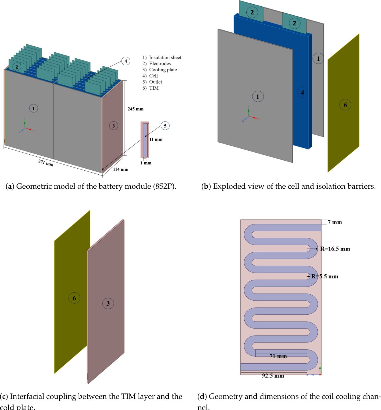
Figure 2.
Grid-independence verification for the 8S2P battery module in terms of maximum temperature , average temperature , and coolant pressure drop ().
Figure 2.
Grid-independence verification for the 8S2P battery module in terms of maximum temperature , average temperature , and coolant pressure drop ().
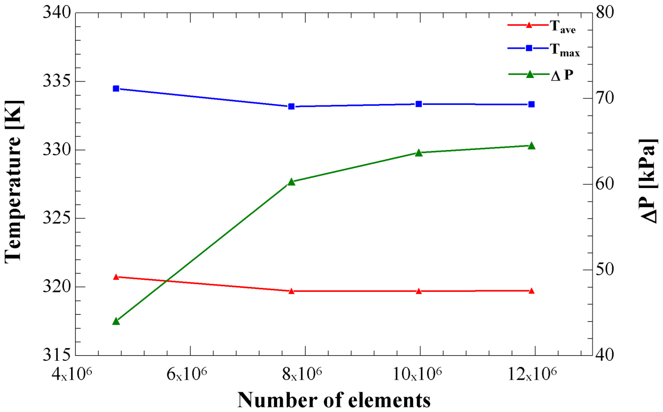
Figure 3.
Comparison of the time evolution of temperature with the experimental measurements reported by Dileep et al. .
Figure 3.
Comparison of the time evolution of temperature with the experimental measurements reported by Dileep et al. .
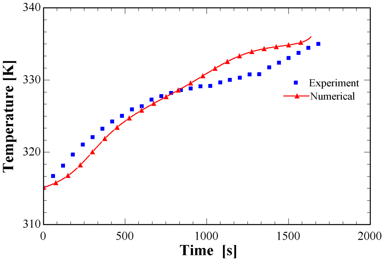
Figure 4.
Spatiotemporal evolution of three-dimensional temperature contours in the 8S2P module over the 2C discharge time () for five thermal-barrier materials: (a) silica aerogel, (b) , (c) Nano SiAG felt, (d) C1.0-PT aerogel, and (e) anisotropic graphite sheet.
Figure 4.
Spatiotemporal evolution of three-dimensional temperature contours in the 8S2P module over the 2C discharge time () for five thermal-barrier materials: (a) silica aerogel, (b) , (c) Nano SiAG felt, (d) C1.0-PT aerogel, and (e) anisotropic graphite sheet.
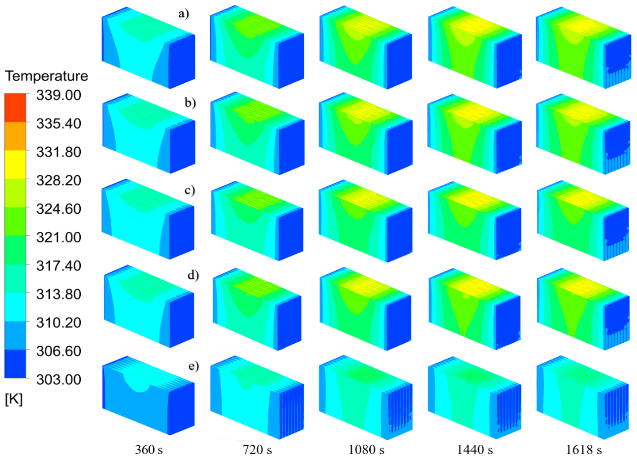
Figure 5.
Quantitative comparison of the maximum temperature () and average temperature in the 8S2P module at the end of the 2C discharge cycle (, ) for the five inter-cell thermal-barrier configurations.
Figure 5.
Quantitative comparison of the maximum temperature () and average temperature in the 8S2P module at the end of the 2C discharge cycle (, ) for the five inter-cell thermal-barrier configurations.
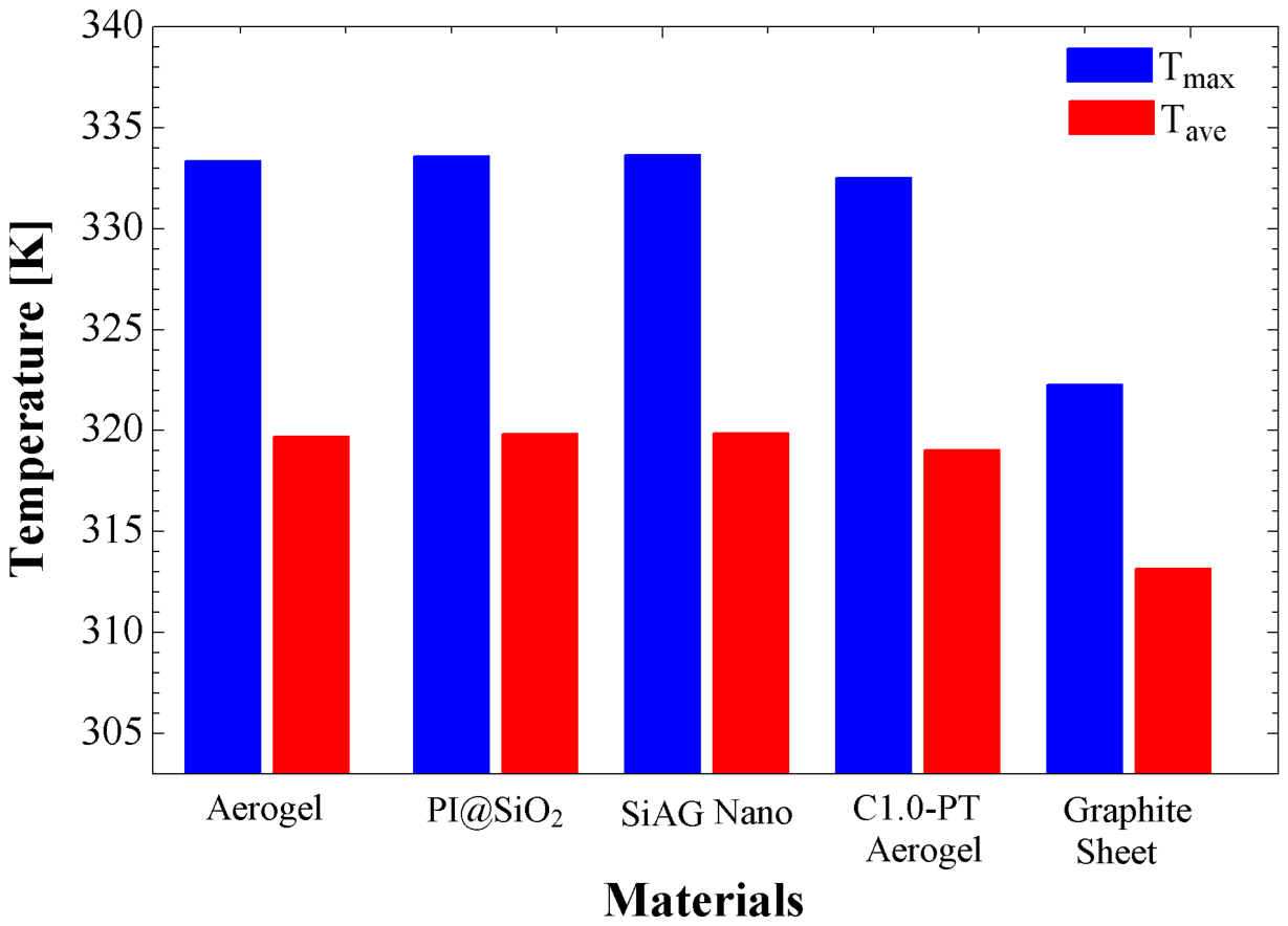
Figure 6.
Three-dimensional distribution of the total volumetric heat generation rate (Total Heat Generation Source, ) in the 8S2P module at the end of the 2C discharge cycle (, ), coupled to the lateral cold-plate system, for the five inter-cell thermal-barrier materials: (a) Aerogel, (b) PI@SiO2/EP-1, (c) Nano SiAG felt, (d) C1.0-PT Aerogel, and (e) Anisotropic Graphite Sheet.
Figure 6.
Three-dimensional distribution of the total volumetric heat generation rate (Total Heat Generation Source, ) in the 8S2P module at the end of the 2C discharge cycle (, ), coupled to the lateral cold-plate system, for the five inter-cell thermal-barrier materials: (a) Aerogel, (b) PI@SiO2/EP-1, (c) Nano SiAG felt, (d) C1.0-PT Aerogel, and (e) Anisotropic Graphite Sheet.
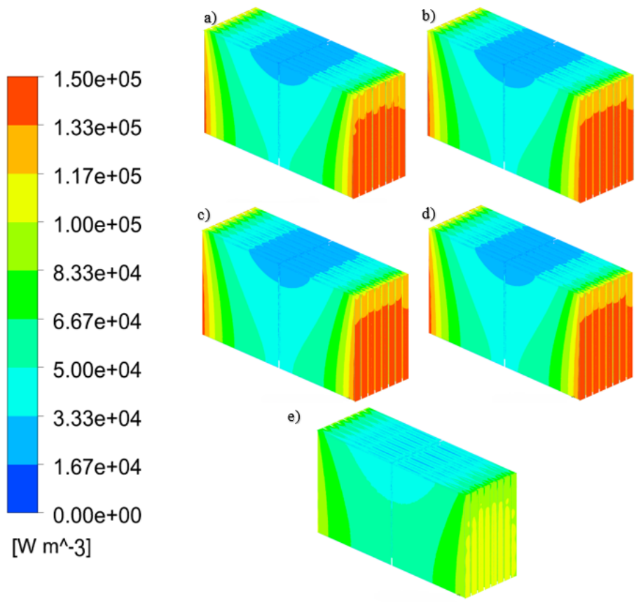
Figure 7.
Quantitative comparison of the heat rejection rate through the cooling plate () in the 8S2P module at the end of the 2C discharge cycle (, ) for the five IS configurations.
Figure 7.
Quantitative comparison of the heat rejection rate through the cooling plate () in the 8S2P module at the end of the 2C discharge cycle (, ) for the five IS configurations.
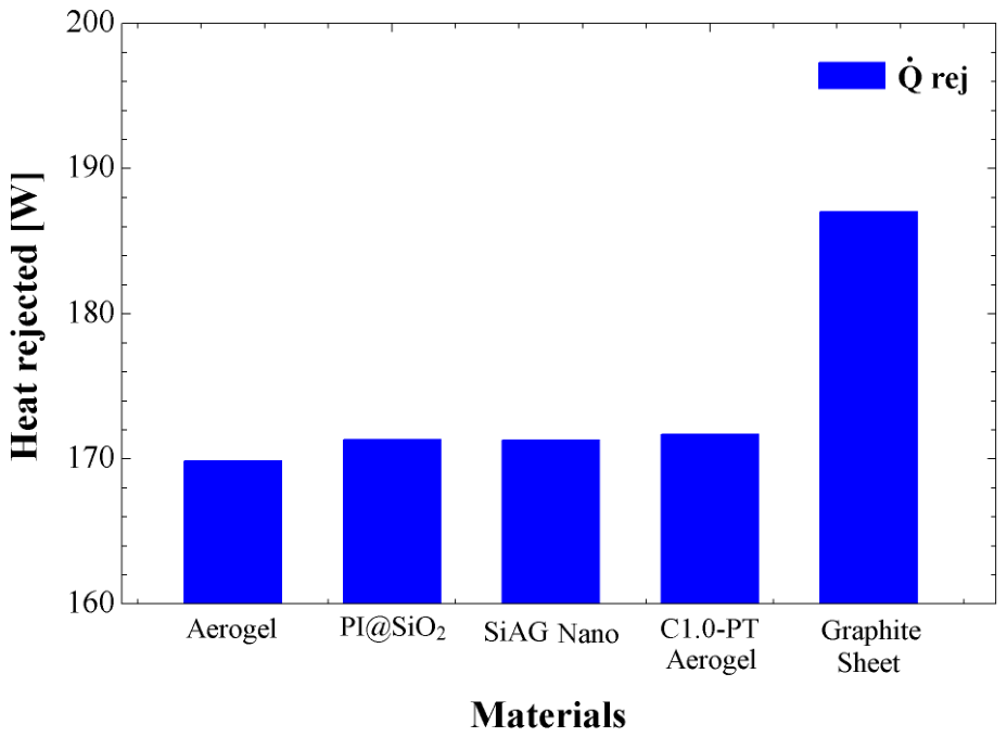
Figure 8.
Spatiotemporal evolution of three-dimensional temperature contours in the 8S2P module during the 2C discharge cycle () for five lateral TIM formulations: (a) Thermal pad, (b) Thermal silicone gel, (c) Mica sheet, (d) VA-3D BN/Polymer, and (e) AlN/PDMS.
Figure 8.
Spatiotemporal evolution of three-dimensional temperature contours in the 8S2P module during the 2C discharge cycle () for five lateral TIM formulations: (a) Thermal pad, (b) Thermal silicone gel, (c) Mica sheet, (d) VA-3D BN/Polymer, and (e) AlN/PDMS.
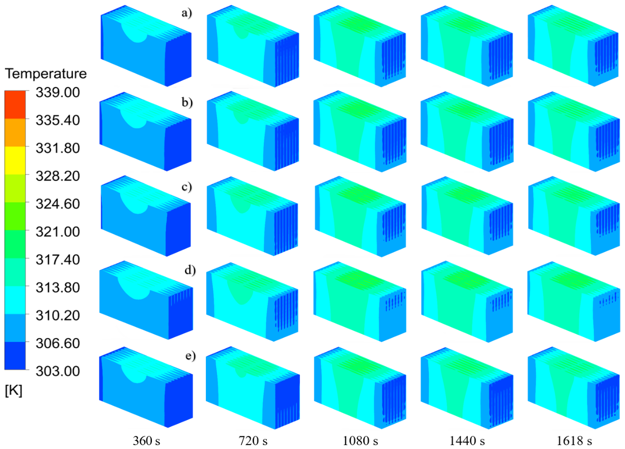
Figure 9.
Quantitative comparison of the maximum temperature () and average temperature in the 8S2P module at the end of the 2C discharge cycle (, ) for the five evaluated thermal interface materials.
Figure 9.
Quantitative comparison of the maximum temperature () and average temperature in the 8S2P module at the end of the 2C discharge cycle (, ) for the five evaluated thermal interface materials.
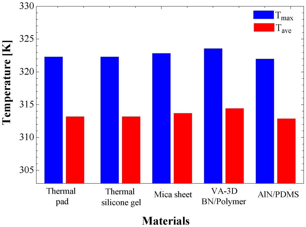
Figure 10.
Three-dimensional distribution of the total volumetric heat generation rate (Total Heat Generation Source, ) in the 8S2P module at the end of the 2C discharge cycle (, ) for the five lateral thermal interface material (TIM) formulations: (a) Thermal pad, (b) Thermal silicone gel, (c) Mica sheet, (d) VA-3D-BN/Polymer, and (e) AlN/PDMS.
Figure 10.
Three-dimensional distribution of the total volumetric heat generation rate (Total Heat Generation Source, ) in the 8S2P module at the end of the 2C discharge cycle (, ) for the five lateral thermal interface material (TIM) formulations: (a) Thermal pad, (b) Thermal silicone gel, (c) Mica sheet, (d) VA-3D-BN/Polymer, and (e) AlN/PDMS.
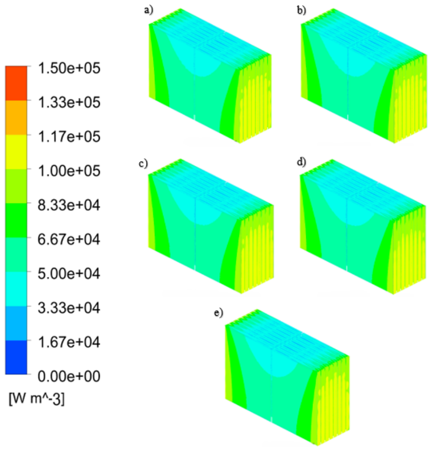
Figure 11.
Quantitative comparison of the net heat rejection rate through the cooling plate () in the 8S2P module at the end of the continuous 2C discharge cycle (, ) for the five lateral thermal interface material (TIM) formulations.
Figure 11.
Quantitative comparison of the net heat rejection rate through the cooling plate () in the 8S2P module at the end of the continuous 2C discharge cycle (, ) for the five lateral thermal interface material (TIM) formulations.
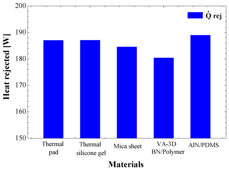

Table 1.
Parameters of the battery characteristics.
| Parameters | Value |
|---|---|
| Nominal Voltage (V) | 3.7 |
| Nominal capacity (Ah) | 60 |
| Anode material | Graphite |
| Nominal Energy (Wh) | 220 |
| Specific energy (Wh/kg) | 196 |
| Dimensions (mm) | 12 × 178.5 × 286 |
| Mass (kg) | 1.120 |
| Cathode material | NMC |
Table 2.
Adjustment of the MSMD-NTGK model parameters [29].
Table 2.
Adjustment of the MSMD-NTGK model parameters [29].
| U | Y | ||
|---|---|---|---|
| 4.0057 | 2282.453 | ||
| -0.91206 | -28989.2 | ||
| 0.05575 | 163504.7 | ||
| -0.88346 | -406241 | ||
| 3.31760 | 456516.8 | ||
| -2.56381 | -189099 |
Table 3.
Thermophysical Properties of Thermal Barrier Materials.
| Barrier Material | Thickness | Density | Thermal Cond. | Specific Heat | Ref. |
|---|---|---|---|---|---|
| d [mm] | [kg/m3] | k [W/(m·K)] | [J/(kg·K)] | ||
| Aerogel | 2 | 165 | 0.065 | 920 | [33] |
| PI@SiO2/EP-1 | 2 | 113 | 0.048 | 1100 | [18] |
| Nano SiAG felt | 2 | 180 | 0.020 | 900 | [11] |
| C1.0-PT Aerogel | 2 | 48.5 | In-plane: 0.0533 / Through-plane: 0.0297 | 1350 | [5] |
| Anisotropic Graphite | 2 | 1000.00 | In-plane: 220.0 / Through-plane: 5.0 | 700 | [26] |
Table 4.
Thermophysical properties of thermal interface materials for cell-to-cooling-plate contact.
Table 4.
Thermophysical properties of thermal interface materials for cell-to-cooling-plate contact.
| Material Name | Thickness | Density | Thermal Conductivity | Specific Heat | Ref. |
|---|---|---|---|---|---|
| e [mm] | [kg/m3] | k [W/(m·K)] | [J/(kg·K)] | ||
| Thermal pad | 1 | 3050–3090 | 2.7–3.3 | 952 | [36] |
| Thermal silicone gel | 1 | 1200–1500 | 2.0–4.0 | 1200–1700 | [1] |
| Mica sheet | 1 | 2000–2800 | 2.0 | 850–1200 | [7] |
| VA-3D-BN/Polymer | 1 | 1350–1450 | In-plane: 1.2–1.5 / Through-plane: 4.5–5.5 | 1150–1250 | [37] |
| AlN/PDMS | 1 | 2200–2350 | 4.19 | 850–920 | [38] |
Disclaimer/Publisher’s Note: The statements, opinions and data contained in all publications are solely those of the individual author(s) and contributor(s) and not of MDPI and/or the editor(s). MDPI and/or the editor(s) disclaim responsibility for any injury to people or property resulting from any ideas, methods, instructions or products referred to in the content. |
© 2026 by the authors. Licensee MDPI, Basel, Switzerland. This article is an open access article distributed under the terms and conditions of the Creative Commons Attribution (CC BY) license.
Copyright: This open access article is published under a Creative Commons CC BY 4.0 license, which permit the free download, distribution, and reuse, provided that the author and preprint are cited in any reuse.