

Submitted:
16 October 2026
Posted:
19 October 2026
You are already at the latest version
Abstract
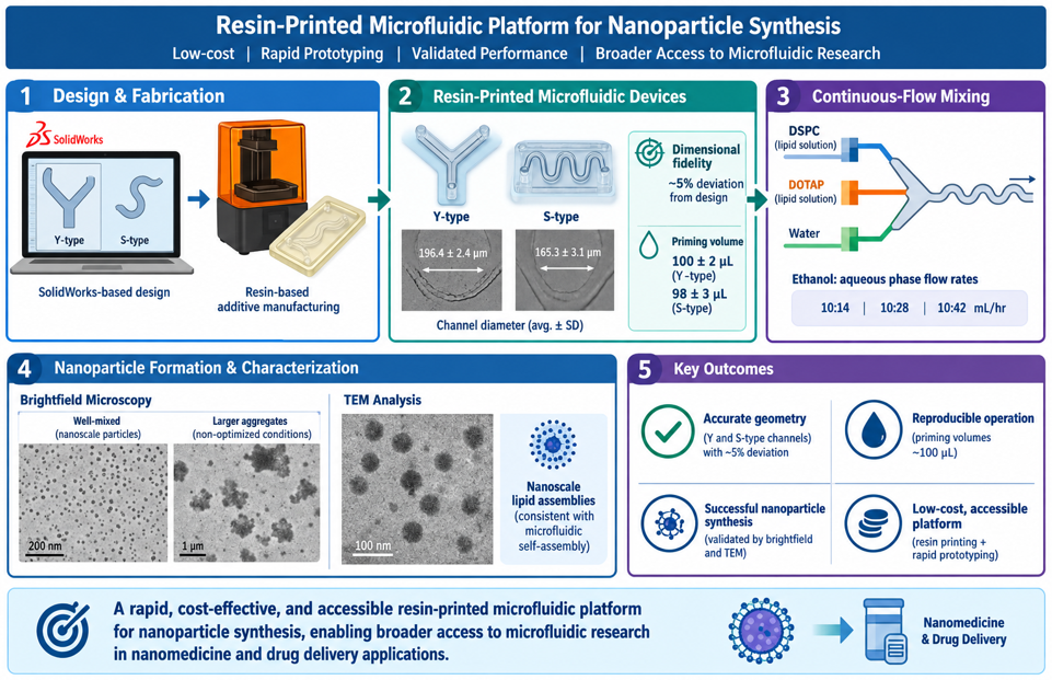
Microfluidic systems enable precise control of fluid transport and nanoscale self-assembly but remain underutilized due to the high cost and complexity of conven-tional microfabrication. Here, we present a low-barrier fabrication and validation workflow for resin-printed microfluidic devices designed for rapid prototyping of na-noparticle synthesis platforms. Using SolidWorks-based design, geometrically distinct Y-shaped and sinusoidal (S-type) microchannels were fabricated via resin-based addi-tive manufacturing and systematically evaluated for dimensional fidelity and hydraulic performance.
Measured average channel diameters (196.4 ± 2.4 μm for Y-type and 165.3 ± 3.1 μm for S-type devices) closely matched design specifications with ~5 % deviation. Priming volume measurements confirmed reproducible fluid handling (100 ± 2 μL and 98 ± 3 μL, respectively). Functional validation was performed using continuous-flow mixing of DSPC and DOTAP lipid solutions and water at ethanol: aqueous phase flow rates of 10:14, 10:28, and 10:42 mL/hr. Brightfield microscopy and transmission electron mi-croscopy (TEM) confirmed formation of nanoscale lipid assemblies consistent with mi-crofluidic self-assembly, while larger aggregates were attributed to incomplete mixing under non-optimized flow conditions and pre-filtration state of formulations.
This work establishes a rapid, cost-effective, and accessible resin-printed microfluidic platform with validated geometric accuracy and functional capability for nanoparticle synthesis, enabling broader access to microfluidic research in nanomedicine and drug delivery applications.
Keywords:
microfluidics
; resin 3D printing
; nanoparticles
; lipid nanoparticles
; additive manufacturing
; drug delivery
1. Introduction
Microfluidics has emerged over the past three decades as one of the most transformative technologies in biomedical engineering, analytical chemistry, diagnostics, and pharmaceutical manufacturing because of its ability to manipulate minute fluid volumes with exceptional precision under well-controlled flow conditions. The miniaturization of fluid handling into micron-scale channels provides several inherent advantages over conventional macroscale processing, including reduced reagent consumption, accelerated heat and mass transfer, enhanced mixing efficiency, improved reaction reproducibility, and the ability to perform high-throughput analyses while minimizing operational costs. These characteristics have enabled microfluidic platforms to become indispensable tools for biological assays, organ-on-chip systems, point-of-care diagnostics, biomaterials development, and increasingly, the synthesis of nanomedicines and advanced drug delivery systems [1,2,3].
The unique fluid dynamics governing microscale flow distinguish microfluidic systems from conventional laboratory reactors. Because transport within microchannels typically occurs under low Reynolds number conditions, flow remains predominantly laminar, enabling highly controlled diffusion-dominated transport. Although laminar flow limits spontaneous turbulent mixing, rationally designed channel architectures such as serpentine, staggered herringbone, and sinusoidal geometries can significantly enhance interfacial transport through chaotic advection, effectively reducing diffusion lengths and enabling rapid reagent mixing without external energy input [4,5,6].
Historically, microfluidic device fabrication has relied heavily on cleanroom-based photolithography and soft lithography techniques adapted from semiconductor manufacturing. The introduction of poly(dimethylsiloxane) (PDMS)-based soft lithography enabled rapid prototyping of microfluidic systems by replicating photolithographically defined masters into elastomeric devices [7,8]. This approach rapidly became the dominant fabrication method due to its simplicity, low cost, optical transparency, and compatibility with biological systems. However, conventional soft lithography remains constrained by significant infrastructure requirements, including access to cleanroom facilities, photomask fabrication, plasma bonding equipment, and trained personnel, thereby limiting accessibility for many laboratories.
In addition to fabrication barriers, PDMS-based systems present intrinsic material limitations, including absorption of hydrophobic molecules, swelling in organic solvents, and hydrophobic recovery following surface treatment, all of which can compromise performance in chemical and pharmaceutical applications [9,10,11]. Alternative fabrication methods, including glass micromachining, hot embossing, injection molding, laser ablation, and CNC micromilling, have been developed to address these challenges; however, they often introduce new constraints in terms of cost, fabrication time, scalability, or geometric flexibility [12,13,14].
Recent advances in additive manufacturing have begun to fundamentally reshape microfluidic fabrication by enabling rapid, low-cost, and highly customizable device production directly from computer-aided design (CAD) models. Among these, resin-based stereolithography (SLA) and digital light processing (DLP) printing have demonstrated particular promise due to their relatively high resolution, smooth surface finish, and ability to fabricate complex three-dimensional geometries in a single step [15,16,17] These technologies eliminate the need for cleanroom processing and enable rapid iterative design cycles, substantially reducing the time from concept to functional prototype.
Modern CAD tools further enhance this capability by enabling rapid generation and modification of complex channel architectures that would be difficult or impossible to achieve using conventional subtractive or molding techniques. As a result, additive manufacturing has opened new opportunities for accessible microfluidic device development across academic, educational, and low-resource research environments, thereby democratizing access to microscale fluid engineering [16,18].
Despite these advances, resin-printed microfluidic systems continue to face challenges related to dimensional accuracy, channel clogging, resin shrinkage, incomplete removal of uncured material, and variability in optical and mechanical properties. Accordingly, rigorous geometric validation and hydraulic characterization remain essential for ensuring reproducible device performance, particularly in applications where small deviations in channel geometry can significantly influence flow behavior and mixing dynamics [15,19].
In this work, we address these limitations by presenting a low-barrier resin-printed microfluidic fabrication and validation workflow that enables rapid design, fabrication, and functional testing of geometrically distinct microfluidic devices for nanoparticle synthesis applications. Using SolidWorks-based CAD design, we developed Y-shaped and sinusoidal (S-type) microchannel architectures with controlled variations in channel geometry and internal diameter. These devices were fabricated using resin-based additive manufacturing and systematically validated through dimensional and hydraulic characterization, including channel diameter measurements and priming volume analysis.
The fabricated devices demonstrate high dimensional fidelity relative to design specifications, and priming volume measurements confirm predictable hydraulic performance consistent with design parameters.
To evaluate functional performance, we further demonstrate lipid nanoparticle formation via single-pass flow mixing of DSPC and DOTAP in aqueous media across flow rates. Brightfield microscopy and TEM confirm the formation of spherical lipid-based nanoparticles spanning nanoscale dimensions, consistent with microfluidic-assisted self-assembly processes.
Collectively, this study establishes a scalable and accessible resin-printed microfluidic platform that bridges the gap between rapid device fabrication and functional nanomedicine applications. By lowering the barrier to entry for microfluidic device design and fabrication, this approach enables broader participation in nanoparticle research, accelerates prototyping of mixing architectures, and provides a practical pathway for cost-effective development of next-generation drug delivery systems.
2. Materials and Methods
Microfluidic Device Design
Two microfluidic device (MFD) geometries, referred to as the S-type and Y-type, were designed to evaluate fluid transport through different channel configurations. The S-type device incorporates an extended serpentine flow path consisting of four rounded 180° turns and two rounded 90° bends. The device includes two inlet ports, each with a diameter of 2 mm, and a single outlet port with a diameter of 1 mm. To promote changes in flow characteristics along the channel, the channel width was reduced by 0.2 mm after each 180° turn. The overall device dimensions are 46.60 mm × 24.50 mm, with a total channel length of approximately 154 mm. The Y-type device consists of two identical upstream inlet channels that merge into a single outlet channel through a Y-shaped junction. Each inlet channel has an internal diameter of 0.2 mm and a length of 100 mm, while the outlet channel has an internal diameter of 0.2 mm and a length of 30 mm. This design provides a simplified geometry for comparison with the more complex serpentine S-type configuration.
Microfluidic Device Fabrication
Microfluidic devices were fabricated using stereolithography (SLA) 3D printing. The experiment used a UV-curable photopolymer resin (405 nm, clear, 1000 g) from Anycubic. Fabrication was performed with the Anycubic Photon Mono 4 10K resin 3D printer, print volume of 6.04” × 3.43” × 6.49” (Anycubic Photon Mono 4). Post-processing utilized the Creality UW-01 Wash and Cure Station (washing size 7.48 × 6.06 × 7.87 inches, Creality UW-01 Wash and Cure Station) along with MaxTite Isopropyl Alcohol (99.9%). Tygon tubing (4 mm inner diameter), sourced from Grainger, North Haven, was also used to construct flow circuit.
To ensure successful fabrication of enclosed microchannels, each device was oriented vertically (90° relative to the build platform) during slicing, with the channel axis aligned perpendicular to the printing bed. This orientation minimized unsupported horizontal channel spans and improved print quality while facilitating the removal of uncured resin from the enclosed channels.
Following printing, the devices were washed in 99.9% isopropyl alcohol (MaxTite) for approximately 2 min using a Creality UW-01 Wash and Cure Station. Prolonged washing was avoided because excessive exposure to isopropyl alcohol can increase material brittleness. Since uncured resin remains trapped within enclosed microchannels after printing, the channels were flushed with fresh isopropyl alcohol using a syringe until all visible resin was removed. Compressed air was then passed through the channels to expel residual solvent and uncured resin. In channels were defects such as asperities, microfibers or occlusion were still present, tetrahydrofuran was washed through the channels to eliminate errors (See Supporting Figure S1).
The cleaned devices were post-cured under ultraviolet light for 2 min using the Creality UW-01 curing station to achieve complete polymerization. After curing, Tygon tubing (4 mm inner diameter) was connected to the inlet and outlet ports to integrate the devices with the experimental flow system following flow fidelity check show in supporting video in Figure S2.
Device Characterization
To characterize printed channels, five MFDs were photographed under microscopy along their channel sections where changes in flow characteristics were expected and channel size differed by design. The images were processed to determine the device diameter, then compared to the design and averaged to understand the printer’s quality and tolerance for microchannels.
Microfluidic channel images were acquired using a Leica fluorescence microscope (Leica DMi8 Inverted Fluorescence IMC Microscope with motorized XY stage, Boston, MA, USA) under appropriate magnification to capture the full channel geometry. Images were saved in a lossless format for subsequent analysis. Channel diameters were quantified using ImageJ (National Institutes of Health, Bethesda, MD, USA). Prior to measurement, the image scale was calibrated using the microscope’s scale bar or known pixel-to-distance conversion. The line measurement tool was used to measure channel diameters perpendicular to the channel walls at representative locations. Multiple measurements were collected for each channel, and the average diameter was calculated for subsequent analysis.
Dimensional analysis was performed as follows: Selected sections of the MFDs, as shown for the S-type case, quantified for channel diameter was done for five devices and the section diameters averaged. Dimensional deviation of printed device from design was calculated as (Design dimension – device dimension)/design dimension x 100.
The priming volume of each microfluidic device was determined experimentally by measuring the minimum volume of liquid required to completely fill the microfluidic channels without entrapped air bubbles. Using a calibrated micropipette, deionized water was introduced through the device inlet in small increments until fluid reached the outlet and all channels were fully occupied. The total dispensed volume was recorded as the device prime volume. Measurements were repeated for three independent devices, and the average prime volume was reported as the mean ± standard deviation.
Nanoparticle Synthesis
For proof of concept, 1,2-dioleoyl-3-trimethylammonium-propane (DOTAP) lipid was used for the formulation experiment in the S-type MFDs. Deionized water was used for all aqueous preparations.
The setup of the experiment is based on a simple flow through the designed microfluidic device using syringe pumps (supporting Figure S3). The device has two inlets. One inlet pushes the lipid in ethanol solution at a constant flow rate, while the second inlet pushes water at three different flow rates (14 mL/hr, 28 mL/hr, and 42 mL/hr).
To formulate lipid nanoparticles two syringe pumps push the fluids at different rates from the syringes. The first inlet is pumped with the DOTAP lipid solution and connected to the first inlet of the microfluidic device using a short silicone tube to minimize waste. Each experiment runs for 10 minutes. The collected solution is gathered in a glass bottle placed at a minimal distance from the microfluidic device so that the drops reach the sample container gently. No post-microfluidic particle formulation processing was done as the focus here is proof of concept. In standard thin-film hydration nanoparticle formulation, samples would be processed by ultra sonification, extrusion, and dialysis to separate out particles with undesired features. This post processing breaks down agglomeration in the sample, allowing proper dispersion. It also enables particle size reduction and results in more uniform particle sizes.
Characterization of Nanoparticles
A small aliquot (5–10 µL) of the nanoparticle suspension was deposited onto a clean glass microscope slide and covered with a glass coverslip to form a thin liquid layer. The sample was imaged using a EVOS FLOID digital microscope (Thermo Fisher, USA) operated in bright-field mode. Images were acquired using a 10× objective lens, and the focus was adjusted manually to obtain clear visualization of nanoparticle aggregates and solution morphology. Multiple fields of view were imaged for each sample under identical illumination and magnification settings to ensure consistency between measurements. Images were captured using the microscope’s integrated imaging software and exported for qualitative analysis.
Nanoparticle morphology was characterized using an HT7800 transmission electron microscope (Hitachi High-Tech, Tokyo, Japan). Samples were imaged under high vacuum using an accelerating voltage of 80 kV. The microscope was operated with a filament voltage of 18 V, a beam current of 10 µA, and a vacuum level of approximately 21 µPa. Transmission electron micrographs were acquired in high contrast mode to evaluate nanoparticle morphology and size distribution.
3. Results
3.1. Device Fabrication and Dimensional Fidelity
As the first step in the experimental workflow (Figure 1), the microfluidic devices were successfully fabricated using resin-based stereolithographic (SLA) 3D printing, producing both the serpentine (S-type) and Y-junction (Y-type) geometries with well-defined internal channels (Figure 2). Visual inspection immediately after printing confirmed complete structural formation without evidence of delamination, collapsed channels, or print defects. Post-processing, including isopropyl alcohol washing, compressed air flushing, and ultraviolet curing, effectively removed uncured resin while preserving channel integrity.
Dimensional characterization demonstrated high agreement between the computer-aided design (CAD) models and the printed devices (Figure 3 and Figure 4, and supporting data Table 1). Measurements collected from multiple locations throughout each device indicated that channel diameter deviations remained within 5% of the design specifications, demonstrating excellent dimensional fidelity despite the small channel dimensions. Such agreement confirms that the selected printing parameters and post-processing protocol are sufficient to reproduce complex microfluidic geometries with high accuracy.
Channel uniformity is particularly important for microfluidic nanoparticle synthesis because variations in channel dimensions directly influence hydraulic resistance, flow velocity, and local mixing behavior. The low dimensional variation observed throughout both device designs indicates that flow conditions remained highly reproducible between fabricated devices, providing a consistent platform for nanoparticle production.
3.2. Hydraulic Performance
Both device geometries exhibited reliable hydraulic performance during operation. Priming volumes measured experimentally closely matched the theoretical internal channel volumes, confirming that printed channels remained fully patent throughout the devices. Following priming, continuous flow was maintained without observable leakage, channel blockage, or bubble formation across the tested flow rates.
Leak-free operation demonstrates the mechanical integrity of the printed devices and confirms successful bonding between printed layers during fabrication. Stable flow behavior is essential for nanoparticle synthesis because fluctuations in flow rate or pressure can alter solvent exchange kinetics and produce broader particle size distributions.
3.3. Mixing Performance (Qualitative/Quantitative)
The two microfluidic geometries were designed to generate different mixing environments. The Y-type device relies primarily on diffusion following the convergence of two inlet streams, whereas the S-type incorporates repeated bends and channel contractions that promote secondary flow development and enhanced convective mixing.
Although both devices produced complete mixing sufficient for nanoparticle formation, the serpentine geometry provides a substantially longer residence time and repeated changes in flow direction, increasing the interfacial area between the aqueous and organic phases. These features are expected to accelerate solvent exchange and create more homogeneous supersaturation conditions throughout the channel.
The observed differences in channel architecture therefore suggest that the S-type device should provide greater control over nanoparticle nucleation and growth than the simpler Y-junction configuration, particularly at higher flow rates where diffusive mixing alone becomes less effective.
3.4. Nanoparticle Formation Results
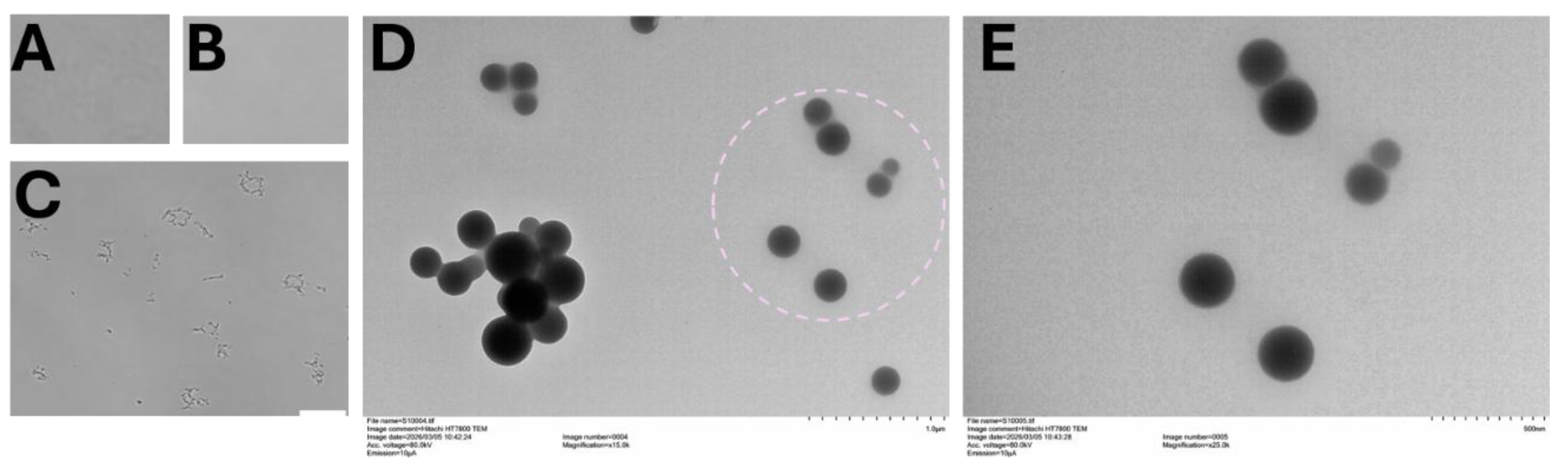
A readily accessible bright-field microscopy demonstrated successful nanoparticle formulation following microfluidic mixing (Figure 5A–C). Control images obtained from a clean glass slide and deionized water showed negligible particulate material, while samples containing lipid formulations displayed numerous suspended particles following processing through the Y-type microfluidic device. This result provided confidence to access offsite higher resolution microscopy instrument for further nanoparticle analysis.
Transmission electron microscopy (Figure 5D,E) confirmed successful nanoparticle formation and provided detailed morphological characterization. Images of DOTAP lipid nanoparticles produced using the S-type device revealed discrete particles with predominantly spherical morphology and minimal evidence of aggregation. Individual nanoparticles appeared relatively uniform in size, indicating controlled nucleation during rapid solvent exchange within the microchannels.
The TEM observations (additional images in supporting Figure S4) validate that the printed microfluidic platform is capable of producing nanoscale lipid particles comparable to those generated using conventional microfluidic synthesis systems. The absence of large aggregates further suggests efficient mixing and controlled self-assembly during formulation.
4. Discussion
4.1. Mechanistic Discussion
Nanoparticle formation in microfluidic systems is governed by the rate of solvent exchange between the ethanol lipid solution and the aqueous phase. Rapid mixing creates localized supersaturation, initiating lipid self-assembly into nanoscale vesicular or lipid nanoparticle structures. Consequently, mixing efficiency directly influences particle nucleation, growth, and final size distribution.
The serpentine geometry enhances this process by increasing residence time and generating repeated changes in flow direction, which improve solvent exchange relative to a simple Y-junction mixer. More homogeneous mixing conditions reduce concentration gradients within the channel, thereby limiting uncontrolled particle growth and aggregation. The uniform nanoparticle morphology observed by TEM is consistent with this mechanism and demonstrates the effectiveness of the printed devices for controlled nanoparticle synthesis.
4.2. Comparison with Literature
Microfluidic devices fabricated from polydimethylsiloxane remain the benchmark platform for laboratory-scale nanoparticle synthesis because of their optical transparency, biocompatibility, and compatibility with soft lithography [1,20]. However, fabrication of PDMS devices requires photolithography, cleanroom facilities, master mold production, plasma bonding, and multiple processing steps, making rapid design iteration both time-consuming and labor-intensive.
Recent advances in high-resolution stereolithography and digital light processing printing have enabled direct fabrication of microfluidic devices with enclosed channels, eliminating the need for molds and significantly reducing fabrication time. Three-dimensional printing also allows rapid modification of channel geometries and integration of complex three-dimensional features that are difficult or impossible to achieve using conventional soft lithography [14,17].
The present SLA-printed devices demonstrated channel dimensional deviations of less than 5% from the CAD design while maintaining leak-free operation and reproducible hydraulic performance. These results compare favorably with previously reported resin-printed microfluidic devices, where dimensional deviations of approximately 5–10% are commonly observed for channels in the 200–500 μm range [21,22]. The successful fabrication of both Y-junction and serpentine geometries further demonstrates the flexibility of additive manufacturing for rapid microfluidic prototyping.
Microfluidic mixing has become the preferred approach for lipid nanoparticle synthesis because rapid and controlled solvent exchange produces highly reproducible nanoparticle populations with narrow size distributions. Earlier studies by Jahn et al. [23] demonstrated that hydrodynamic focusing enables controlled liposome formation by regulating solvent dilution kinetics, while subsequent work showed that microfluidic mixing substantially improves the reproducibility and scalability of lipid nanoparticle production compared with conventional bulk mixing techniques [24]. More recently, microfluidic mixing was reported as a scalable manufacturing platform for messenger RNA lipid nanoparticles used in nucleic acid delivery [25].
Consistent with these reports, the present study demonstrates that SLA-fabricated microfluidic devices provide sufficient dimensional accuracy and hydraulic stability to support lipid nanoparticle self-assembly. Bright-field microscopy confirmed particle formation, while TEM imaging revealed discrete, predominantly spherical nanoparticles with minimal aggregation. Although the current work primarily establishes proof-of-concept fabrication and device validation rather than optimization of nanoparticle characteristics, the results indicate that resin-printed microfluidic devices can serve as practical alternatives to traditional PDMS systems for nanoparticle synthesis. Their rapid fabrication, low production cost, and ability to accommodate iterative design modifications make them particularly attractive for accelerating the development and optimization of microfluidic platforms for drug delivery, gene therapy, and nanomedicine applications.
5. Conclusions
This study demonstrates that resin-based additive manufacturing provides a practical and accessible approach for fabricating microfluidic devices capable of supporting continuous-flow nanoparticle synthesis. The fabricated Y-shaped and sinusoidal microchannels exhibited high dimensional fidelity relative to their computer-aided designs, reproducible fluid handling characteristics, and reliable hydraulic performance. Functional validation through the continuous-flow mixing of DSPC and DOTAP lipid solutions confirmed the ability of the printed devices to facilitate lipid self-assembly, with microscopy analyses verifying the formation of nanoscale lipid structures. Although larger aggregates were observed under the tested operating conditions, our prior work [26] nanoparticle formulation via thin film hydration showed such aggregates can filtered, and therefore these results emphasize the importance of optimizing flow parameters and dialyzing formulations rather than limitations of the fabrication approach itself.
Overall, the presented workflow establishes a rapid, low-cost, and reproducible strategy for the design, fabrication, and validation of microfluidic devices using commercially available resin printing technologies. By reducing the barriers associated with conventional cleanroom-based microfabrication, this platform enables rapid iteration of device geometries and expands access to microfluidic technologies for nanoparticle formulation. Future work will focus on optimizing channel architectures and operating conditions to improve mixing efficiency, achieve tighter nanoparticle size distributions, and extend the platform to a wider range of nanomedicine and drug delivery applications.
Supplementary Materials
The following supporting information can be downloaded at the website of this paper posted on Preprints.org, Figure S1: Smoothening of microchannel surfaces. Microfibers, asperities, or channel occlusion (A, B) resulting from manufacturing limitations including light scattering were addressed by a single pass tetrahydrofuran (THF) flow (C). Panel D shows THF washed channels.; Figure S2: Video of flow through S-type microfluidic device.; Table S1: Devices validation data; Figure S3: DOTAP lipid nanoparticle formulation using S-type microfluidic device set up.; Figure S4: DOTAP lipid nanoparticle formulated at 14:10 mL/hr aqueous to ethanol phase flow rate A), 28:10 mL/hr aqueous to ethanol phase flow rate B), and C) 42:10 mL/hr aqueous to ethanol phase flow rate using S-type microfluidic device. As the rate increases, greater variation in the shape of formulated particles is observed, along with the formation of snowflake-like structures that surround the nanoparticles. Additionally, crystalline features become more prominent at higher flow rates. This warrants filtration/dialysis to isolate desired particles.
Author Contributions
Conceptualization, K.A. and S.P.; methodology, K.A. and C. W. and C.W.; software, K.A.; validation, S.P., K.A. and Z.Z.; formal analysis, K.A.; investigation, S.P.; resources, K.A.; data curation, K.A and S.P.; writing—original draft preparation, S.P.; writing—review and editing, K.A. and C.W. and C.W.; visualization, K.A. and S.P.; supervision, K.A.; project administration, K.A.; funding acquisition, K.A. All authors have read and agreed to the published version of the manuscript.
Funding
Research reported in this publication was supported by the National Heart, Lung, And Blood Institute of the National Institutes of Health under Award Number R15HL188996. The content is solely the responsibility of the authors and does not necessarily represent the official views of the National Institutes of Health.
Institutional Review Board Statement
Not applicable.
Informed Consent Statement
Not applicable.
Data Availability Statement
The raw data supporting the conclusions of this article will be made available by the authors on request.
Acknowledgments
The authors are thankful to Biotrafix LLC for access to the SLA printer and for Connecticut Agricultural Station’s TEM facility access.
Conflicts of Interest
The authors declare no conflicts of interest.
Abbreviations
The following abbreviations are used in this manuscript:
| PDMS | poly(dimethylsiloxane) |
| TEM | Transmission electron microscopy |
| CNC | Computer Numeric Control |
| CAD | Computer Aided Design |
| SLA | Stereolithography |
| DLP | Digital light processing |
| DOTAP | 1,2-dioleoyl-3-trimethylammonium-propane |
| DSPC | Distearoylphosphatidylcholine |
References
- Whitesides, G.M. The origins and the future of microfluidics. Nature 2006, 442, 368–373. [Google Scholar] [CrossRef] [PubMed]
- Squires, T.M.; Quake, S.R. Microfluidics: Fluid physics at the nanoliter scale. Rev. Mod. Phys. 2005, 77, 977–1026. [Google Scholar] [CrossRef]
- Sackmann, E.K.; Fulton, A.L.; Beebe, D.J. The present and future role of microfluidics in biomedical research. Nature 2014, 507, 181–189. [Google Scholar] [CrossRef] [PubMed]
- Stroock, A.D.; et al. Chaotic mixer for microchannels. Science 2002, 295, 647–651. [Google Scholar] [CrossRef] [PubMed]
- Mao, X.; Lin, S.-C.S.; Dong, C.; Huang, T.J. Single-layer planar on-chip flow cytometer using microfluidic drifting based three-dimensional (3D) hydrodynamic focusing. Lab Chip 2009, 9, 1583–1589. [Google Scholar] [CrossRef] [PubMed]
- Vogelaar, A.; Marcotte, S.; Cheng, J.; Oluoch, B.; Zaro, J. Use of Microfluidics to Prepare Lipid-Based Nanocarriers. Pharmaceutics 2023, 15, 1053. [Google Scholar] [CrossRef] [PubMed]
- McDonald, J.C.; Whitesides, G.M. Poly(dimethylsiloxane) as a Material for Fabricating Microfluidic Devices. Acc. Chem. Res. 2002, 35, 491–499. [Google Scholar] [CrossRef] [PubMed]
- Duffy, D.C.; et al. Rapid prototyping of microfluidic systems. Anal. Chem. 1998, 70, 4974–4984. [Google Scholar] [CrossRef] [PubMed]
- Hou, X.; Zaks, T.; Langer, R.; Dong, Y. Lipid nanoparticles for mRNA delivery. Nat. Rev. Mater. 2021, 6, 1078–1094. [Google Scholar] [CrossRef] [PubMed]
- Verbeke, R.; Lentacker, I.; De Smedt, S.C.; Dewitte, H. The dawn of mRNA vaccines: The COVID-19 case. J. Control. Release 2021, 333, 511–520. [Google Scholar] [CrossRef] [PubMed]
- Cullis, P.R.; Hope, M.J. Lipid nanoparticle systems for gene therapy. Mol. Ther. 2017, 25, 1467–1475. [Google Scholar] [CrossRef] [PubMed]
- Scott, S.M.; Ali, Z. Fabrication Methods for Microfluidic Devices: An Overview. Micromachines 2021, 12(3), 319. [Google Scholar] [CrossRef] [PubMed]
- Au, A.K.; Huynh, W.; Horowitz, L.F.; Folch, A. 3D-Printed Microfluidics. Angew. Chem. Int. Ed. 2016, 55, 3862–3881. [Google Scholar] [CrossRef] [PubMed]
- Waheed, S.; Cabot, J.M.; Macdonald, N.P.; Lewis, T.; Guijt, R.M.; Paull, B.; Breadmore, M.C. 3D Printed Microfluidic Devices: Enablers and Barriers. Lab Chip 2016, 16, 1993–2013. [Google Scholar] [CrossRef] [PubMed]
- He, Y.; Wu, Y.; Fu, J.-z.; Gao, Q.; Qiu, J.-j. Developments of 3D Printing Microfluidics and Applications in Chemistry and Biology: a Review. Electroanalysis 2016, 28, 1658–1678. [Google Scholar] [CrossRef]
- Au, A.K.; Bhattacharjee, N.; Horowitz, L.F.; Chang, T.C.; Folch, A. 3D-Printed Microfluidic Automation. Lab Chip 2015, 15, 1934–1941. [Google Scholar] [CrossRef] [PubMed]
- Bhattacharjee, N.; Urrios, A.; Kang, S.; Folch, A. The upcoming 3D-printing revolution in microfluidics. Lab Chip 2016, 16, 1720–1742. [Google Scholar] [CrossRef] [PubMed]
- Gross, B.C.; Erkal, J.L.; Lockwood, S.Y.; Chen, C.; Spence, D.M. Evaluation of 3D Printing and Its Potential Impact on Biotechnology and the Chemical Sciences. Anal. Chem. 2014, 86, 3240–3253. [Google Scholar] [CrossRef] [PubMed]
- Ligon, S.C.; Liska, R.; Stampfl, J.; Gurr, M.; Mülhaupt, R. Polymers for 3D Printing and Customized Additive Manufacturing. Chem. Rev. 2017, 117, 10212–10290. [Google Scholar] [CrossRef] [PubMed]
- Whitesides, G.M.; Ostuni, E.; Takayama, S.; Jiang, X.; Ingber, D.E. Soft Lithography in Biology and Biochemistry. Annu. Rev. Biomed. Eng. 2001, 3, 335–373. [Google Scholar] [CrossRef] [PubMed]
- Qiu, J.; Li, J.; Guo, Z.; Zhang, Y.; Nie, B.; Qi, G.; Zhang, X.; Zhang, J.; Wei, R. 3D Printing of Individualized Microfluidic Chips with DLP-Based Printer. Materials 2023, 16(21), 6984. [Google Scholar] [CrossRef] [PubMed]
- Gong, H.; Beauchamp, M.; Perry, S.; Woolley, A.T.; Nordin, G.P. Optical Approach to Resin Formulation for 3D Printed Microfluidics. RSC Adv. 2015, 5, 106621–106632. [Google Scholar] [CrossRef] [PubMed]
- Jahn, A.; Vreeland, W.N.; Gaitan, M.; Locascio, L.E. Controlled Vesicle Self-Assembly in Microfluidic Channels with Hydrodynamic Focusing. J. Am. Chem. Soc. 2004, 126, 2674–2675. [Google Scholar] [CrossRef] [PubMed]
- Zhigaltsev, I.V.; Belliveau, N.; Hafez, I.; et al. Bottom-Up Design and Synthesis of Limit Size Lipid Nanoparticle Systems with Aqueous-Based Microfluidic Mixing. Langmuir 2012, 28, 3633–3640. [Google Scholar] [CrossRef] [PubMed]
- Belliveau, N.M.; Huft, J.; Lin, P.J.C.; et al. Microfluidic Synthesis of Highly Potent Limit-Size Lipid Nanoparticles for In Vivo Delivery of siRNA. Mol. Ther.–Nucleic Acids 2012, 1, e37. [Google Scholar] [CrossRef] [PubMed]
- Majin, S.; Malik, A.; Poudel, P.; Faustino, E.V.S.; Zuverza-Mena, N.; Hwa, J.; Takyar, S.; Shea, S.; Amoako, K.A. Drug-loaded nanoparticles reduced platelet aggregation and blood coagulation. Front. Med. Technol. 2026, 7, 1690389. [Google Scholar] [CrossRef] [PubMed]
Figure 1.
Microfluidic device design, fabrication, and quality control workflow.
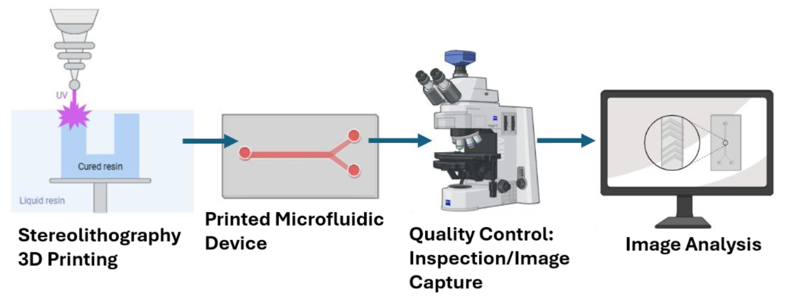
Figure 2.
Microfluidic Device Design and Fabrication. The S-type device design (A, B) showing the serpentine flow path with four rounded 180° turns, two 90° bends, dual 2-mm inlets, and a 1-mm outlet. The channel width is reduced by 0.2 mm after each major turn, resulting in an overall device size of 46.6 × 24.5 mm and a total flow path length of approximately 154 mm and print © before post print processing show size, channel dimension and print at scale. The Y-type device design consisting of two identical upstream inlet channels (ID 0.2 mm, total channel length100 mm) merging into a single outlet channel (ID 0.2 mm, total channel length 30 mm) (D, E), primed device ©, channel wash with 99.9% isopropyl alcohol (F), and channel fidelity inspection by illumination (G) were performed as part of the print validation. Similar device channel wash (H) and drying with compressed air (I) were performed on the S-type models before ultra-violet curing for 2 minutes.
Figure 2.
Microfluidic Device Design and Fabrication. The S-type device design (A, B) showing the serpentine flow path with four rounded 180° turns, two 90° bends, dual 2-mm inlets, and a 1-mm outlet. The channel width is reduced by 0.2 mm after each major turn, resulting in an overall device size of 46.6 × 24.5 mm and a total flow path length of approximately 154 mm and print © before post print processing show size, channel dimension and print at scale. The Y-type device design consisting of two identical upstream inlet channels (ID 0.2 mm, total channel length100 mm) merging into a single outlet channel (ID 0.2 mm, total channel length 30 mm) (D, E), primed device ©, channel wash with 99.9% isopropyl alcohol (F), and channel fidelity inspection by illumination (G) were performed as part of the print validation. Similar device channel wash (H) and drying with compressed air (I) were performed on the S-type models before ultra-violet curing for 2 minutes.
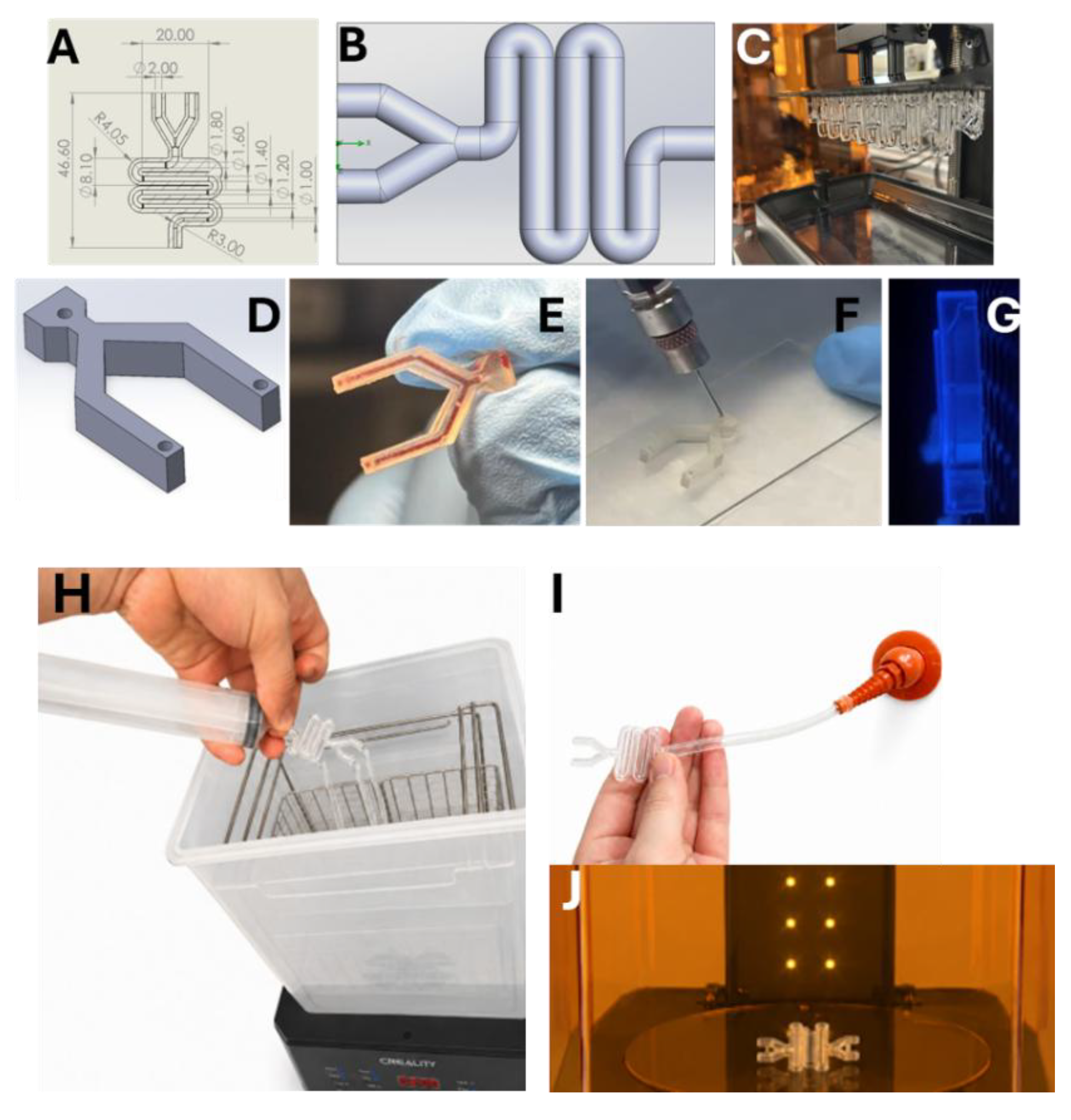
Figure 3.
Microfluidic Device Design Characterization. Several points of interest on the S and Y types device designs (A) were analyzed after fabrication to assess channel diameters (B), and measured prime volume (C), and leak-free flow quality control (D) were done for each device.
Figure 3.
Microfluidic Device Design Characterization. Several points of interest on the S and Y types device designs (A) were analyzed after fabrication to assess channel diameters (B), and measured prime volume (C), and leak-free flow quality control (D) were done for each device.
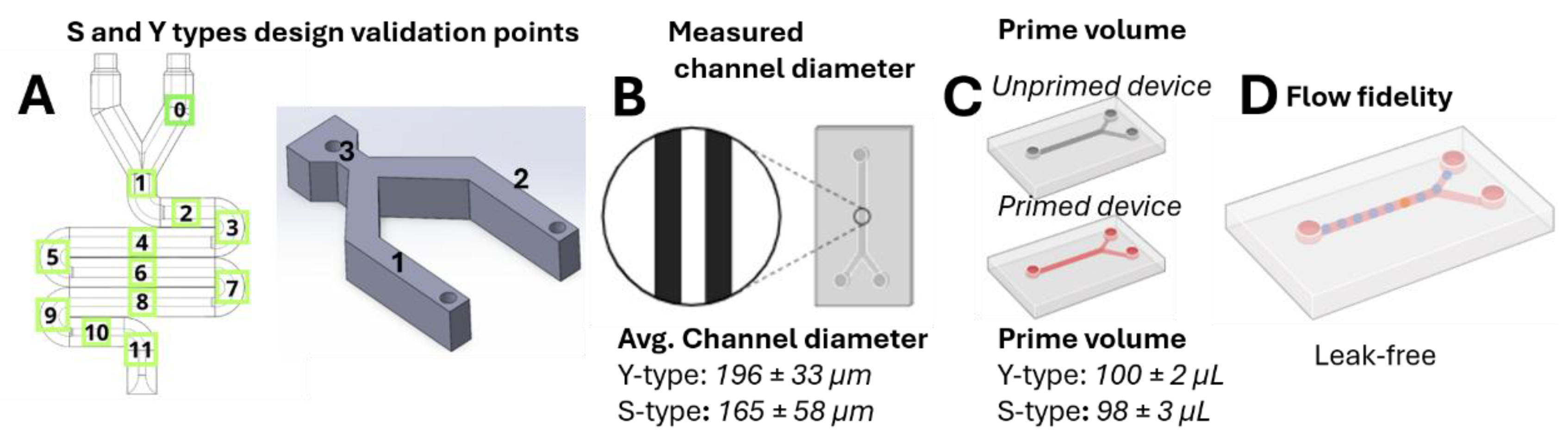
Figure 4.
Microfluidic Device Validation. S-type (A) and Y-type (B) microfluidic devices validation data describing deviations of measured channel diameters in printed devices from their designs. Deviation, calculated as (design dimension – device dimension)/design dimension x 100, were within 5% of the device design specification.
Figure 4.
Microfluidic Device Validation. S-type (A) and Y-type (B) microfluidic devices validation data describing deviations of measured channel diameters in printed devices from their designs. Deviation, calculated as (design dimension – device dimension)/design dimension x 100, were within 5% of the device design specification.
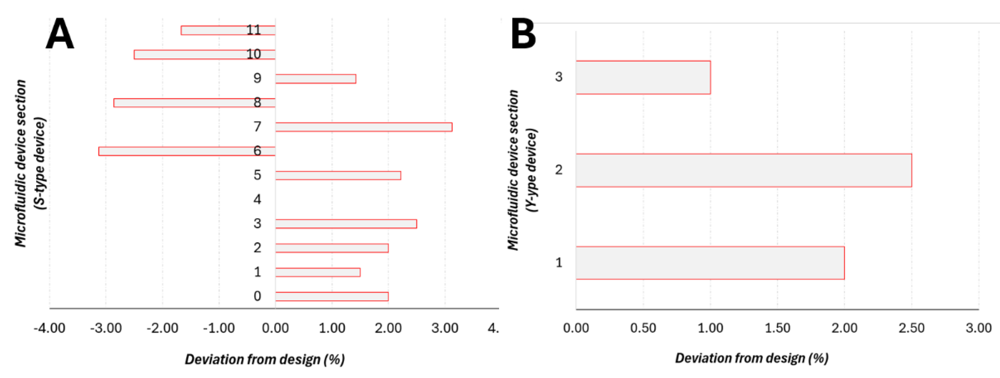
Figure 5.
Nanoparticle Formation Results. Panels A-C respectively show bright field images of microscope glass slide surface A), wetted with deionized water B), and DOPE lipid formulated nanoparticles using the Y-type microfluidic device at 10 mL/hr flow rate C). Images (A-C) were taken with a Floyd imager. Panels D and E are TEMs of DOTAP lipid formulated nanoparticles using the S-type microfluidic device at 14:10 mL/hr aqueous to ethanol phase flow rate. Scale bars: C (100 µm), D (1 µm), E (500 nm).
Figure 5.
Nanoparticle Formation Results. Panels A-C respectively show bright field images of microscope glass slide surface A), wetted with deionized water B), and DOPE lipid formulated nanoparticles using the Y-type microfluidic device at 10 mL/hr flow rate C). Images (A-C) were taken with a Floyd imager. Panels D and E are TEMs of DOTAP lipid formulated nanoparticles using the S-type microfluidic device at 14:10 mL/hr aqueous to ethanol phase flow rate. Scale bars: C (100 µm), D (1 µm), E (500 nm).
Disclaimer/Publisher’s Note: The statements, opinions and data contained in all publications are solely those of the individual author(s) and contributor(s) and not of MDPI and/or the editor(s). MDPI and/or the editor(s) disclaim responsibility for any injury to people or property resulting from any ideas, methods, instructions or products referred to in the content. |
© 2026 by the authors. Licensee MDPI, Basel, Switzerland. This article is an open access article distributed under the terms and conditions of the Creative Commons Attribution (CC BY) license.
Copyright: This open access article is published under a Creative Commons CC BY 4.0 license, which permit the free download, distribution, and reuse, provided that the author and preprint are cited in any reuse.