

Submitted:
14 October 2026
Posted:
15 October 2026
You are already at the latest version
Abstract
Female pelvic organ prolapse (POP) is a gynecological disorder characterized by pelvic organ descent that significantly impacts quality of life. With increasing global burden, approaches for early diagnosis are essential. This study illustrates a patient-specific computational model of the pelvic cavity, updating the uterine and cervical geometric model and assigning cervical tissue properties. Three distinct uterine geometric models were assembled, based on literature measurements and magnetic resonance images for comparison and validation. Human cervical properties were extrapolated from biomechanical testing of ovine pelvic tissues. Finite elements simulations of the Valsalva maneuver were conducted to analyze the biomechanical effects of varying uterine morphology and tissue properties on the pelvic cavity, including the bladder neck, vagina, and uterosacral ligaments (USLs). Results show that a uterus with softer properties assigned exhibits less vertical displacement and relies more on USLs support than a stiffer one. Furthermore, uterine volume and morphology significantly influence pelvic dynamics: a larger uterus tends toward anteversion, while a smaller uterus increases vertical vaginal displacement (10.57 mm vs 6.04 mm) and requires greater USLs support. Anatomical variations directly constrain bladder neck displacement. These computational advancements aim to enhance patient-specific modeling, assisting clinical decision-making.
Keywords:
finite elements analysis
; patient-specific model
; pelvic biomechanics
; pelvic organ prolapse
1. Introduction
Pelvic organ prolapse (POP) is a gynecological disorder that causes an abnormal descent of pelvic organs, including the uterus, rectum, and bladder, into or beyond the vagina [1,2]. This condition arises from the weakening of the pelvic floor muscles, fascia, and ligaments that support the pelvic organs [2], and is associated with risk factors such as aging, vaginal delivery, and induced high intra-abdominal pressure (IAP) [3]. Common symptoms include pelvic pressure, vaginal bulge, difficulty with urination or defecation, and, in more severe cases, urinary or fecal incontinence and sexual dysfunction [2]. Treatment options range from non-surgical approaches, such as pelvic floor muscle training or pessary insertion, to surgical interventions, for severe cases depending on the severity of prolapse [4]. Surgery remains the primary treatment option, with approximately one in ten women worldwide expected to require it during their lifetime [5], and the global number of POP-related surgeries is projected to increase by 48.2% between 2010 and 2050 [6]. Despite the availability of these treatment strategies, none has proven to be effective long-term.
To address this need, increasing efforts have focused on characterizing the anatomy and biomechanics of the female pelvic cavity to better understand the mechanisms underlying POP. Medical imaging techniques, particularly magnetic resonance (MR) imaging, have enabled detailed visualization of pelvic structures and their behavior under loads, supporting the segmentation of patient-derived geometries and the identification of reference dimensions [7,8].
Studies characterizing uterine morphology have considered anatomical variability among women, depending on parity, age, and reproductive stage, which directly affects the loads and displacements experienced by the uterus and its supporting structures [9]. Complementing the anatomical characterization, mechanical testing of pelvic tissues, such as uniaxial and biaxial tensile tests, helps to describe the viscoelastic behavior of biological tissues such as the vagina, uterus, and cervix [10], which are typically represented through hyperelastic constitutive models, such as the Yeoh and Ogden formulations, in computational simulations [11].
The finite elements method has become the preferred methodology for simulating the mechanical behavior of the pelvic structures. Patient-specific computational models, reconstructed from MR images and assigned tissue properties derived from biomechanical testing, have been employed to simulate physiological maneuvers such as Valsalva and to evaluate the resulting displacement of pelvic structures [3,12,13]. Other studies have applied inverse finite element analysis to estimate in vivo tissue properties from medical imaging-derived displacement data [14,15], while further work has assessed the effect of ligament impairment and surgical mesh reinforcement on pelvic organ support [6,16]. However, most of these models rely on simplified or generic uterine geometries, and few have attempted to simulate the progressive descent of the uterus characteristic of prolapse itself, as opposed to organ displacement under a single loading condition [9,17].
Given this gap between the biomechanical characterization of individual pelvic structures, the present study proposes the development and personalization of a computational model of the uterus. Specifically, this work aims to (i) apply a patient-specific geometric model of the uterus based on MR imaging-derived measurements and literature values to obtain different representations of the organ; (ii) assign mechanical properties to the uterine, cervical, and vaginal regions obtained through biomechanical testing; and (iii) evaluate the effect of uterine morphology and tissue properties on the mechanical response of adjacent pelvic structures. By integrating patient-specific geometry, experimentally determined tissue properties, and finite element simulation, this work seeks to contribute toward more anatomically accurate and clinically relevant computational tools to support the evaluation and treatment of POP.
2. Materials and Methods
The computational model of the pelvic cavity was developed by Brandão et al. [18], based on data from a 24-year-old nulliparous woman (see Figure 1(a)). The model is based on MR images, from which the pelvic structures were segmented using the Inventor software (Autodesk, San Raphael, CA, USA) and then discretized into a finite elements mesh in Abaqus software v.6.12 (Dassault Systèmes Simulia Corp., Providence, RI, USA) [12].
In the present work, the original geometric model, which will be designated as the control model (CM), of the uterus, cervix, and vagina [18] (Figure 1(b)), will be adjusted for uterine morphology and biomechanical properties for later assessment of the effects of these variables on the displacement of the uterus and adjacent structures under a Valsalva maneuver by applying a pressure of 4.0 kPa [18].
2.1. Morphological Adaptations of the Uterus, Cervix, and Vagina Geometric Models
Two new geometric models were developed in SolidWorks 2025 (Dassault Systèmes SolidWorks Corp., Waltham, MA, USA): (i) a patient-based model (PM), based on measurements obtained from MR images of a patient, and (ii) a literature-based model (LM), based on dimensions reported in the literature.
The geometric model of the uterus and cervix from the PM was developed using measurements obtained from MR images of a healthy 20-year-old nulliparous woman. In Figure 2, representative sagittal and axial MR images with anatomical measurements are shown. The Research Ethics Committee of the Unidade Local de Saúde de São João–EPE, Porto, Portugal (protocol: IRB138/19) gave full approval.
The geometric model of the uterus and cervix from the LM was based on dimensions obtained from Louwagie et al. [19], and Chen et al. [20].
Louwagie et al. [8] have also defined parametric measurements of uterine and cervical morphology (Figure 3), which were employed to assemble the PM and LM (Table 1) in SolidWorks, providing a guideline when defining such structures in a virtual environment.
Referring to the PM and Figure 2, through the length (A), it is possible to acquire UT1, UD1, and CL. The height (B) provides UT2, UD2, and UD3, while the width (C) provides UT3 and UD4. The remaining parameters were also directly acquired from medical images to assemble the PM (Figure 4(a)).
In the case of the uterus and cervix of the LM (Figure 4(b)), the values shown in Table 1 where directly obtained from Louwagie et al. [19], and Chen et al. [20]. Some key parameters from the uterus and cervix of the CM were also retrieved through features available in the Abaqus software. However, not all available parameters were feasible to be accurately measured since these structures of the CM are greatly simplified.
The geometric model of the vaginal canal from the model developed by Brandão et al. [18] was adapted to accommodate the new geometric models of the uterus and cervix in SolidWorks.
A volumetric assessment through the features of the SolidWorks and Abaqus software resulted in the following volumes for the CM, PM, and LM, respectively: mm3, mm3, and mm3. It is important to note that these values consider both the bulk content of the geometric models and the volume of the uterine cavity.
This approach aims evaluating the effect of uterine and cervical morphology from the different pelvic models, once the biomechanical properties of the tissues are updated. Furthermore, the response of other pelvic structures will also be considered.
2.2. Biomechanical Properties of Cervical Tissues
The vagina, cervix, and uterus of the CM are assigned the properties of vaginal tissue. Hence, uniaxial tensile tests were performed with ovine cervical tissue to update the properties of the uterus and cervical regions of the geometric models. Ovine tissues were chosen as they provide a more accessible option and present morphological similarities to human structures [21]. Cervical and vaginal tissues of adult sheep were obtained from the slaughterhouse PEC Nordeste - Indústria de Produtos Pecuários do Norte, S. A. (NCV D 73). It is important to note that the parity of these animals was not determined. For this study, full approval was obtained from DGAV – Direção-Geral da Alimentação e Veterinária, Porto, Portugal (protocol: N19128UDER). All procedures complied with the regulations outlined in Regulation (EC) No. 1069/2009, dated October 21, 2023.
Tissue samples (10 × 50 mm) were obtained using a cutting die. Three samples were collected from each tissue type (ovine vagina and cervix) (Figure 5(a) and Figure 5(b), respectively). The samples were subjected to uniaxial tensile testing until failure at a displacement rate of 10 mm/min. Mechanical testing was performed using a Mecmesin MultiTest 10-i equipped with a 500 N load cell.
The thickness of each tissue type was measured to calculate the initial cross-section (), therefore obtaining the engineering stress, according to Equation (1). The gauge length of each sample () was also noted to calculate strain, according to Equation (2).
Since every sample presents a unique strain range, for each tissue type, the range of values used was narrowed down until the smallest final strain value was reached. From these data, the average stress for each tissue was calculated, and polynomial trend lines were assigned for the stress-strain relationship of each tissue type.
The properties of human vaginal tissue were retrieved from Rubod et al. [22]. Due to the limited availability of human mechanical properties for the cervix in the literature, the relative mechanical relationships observed between ovine vaginal and cervical tissues were used to estimate the corresponding human tissue behavior. The experimentally determined ovine tissue ratios were combined with the available human vaginal data to extrapolate the stress-strain response of the human cervix, as shown in Equation (3).
The stress-strain curve of the human vagina, along with the resulting curve from interpolation for the human cervix, are shown in Figure 5(c).
The biomechanical behavior of these tissues can be translated into simulated environments by hyperelastic constitutive models, since they are highly deformable and, when under large deformations, present near-incompressibility, translated into isochoric deformations [17]. They are modeled according to strain energy density functions () which represent the total amount of stored energy in a certain element when deformed and vary according to the chosen model [6,23].
The Yeoh constitutive model is best suited for incompressible materials [17], with the respective strain energy density function shown in Equation (4) [6]. The characteristic near-incompressibility is mathematically converted to a compressibility constraint [6].
represents material constants empirically determined for the material used. is the first invariant (see Equation (5)) of the right Cauchy-Green tensor (see Equation (6)).
For uniaxial tensile tests, the fibers composing biological tissues align according to the stretching direction . Therefore, the deformation gradient is presented as follows in Equation (7), where is the elongation ratio in the -direction [11].
Equation (8) represents the Abaqus variation of the Ogden model, where are the principal stretches, and are material properties (strain exponent and strain component, respectively [23]) experimentally measured. N is the order of the model [6].
A fitting process must be performed to attribute a hyperelastic constitutive model to each tissue. Therefore, the Yeoh and Ogden (from first to third order) constitutive models were evaluated in the Abaqus software.
The stress formulas associated with the Yeoh and Ogden constitutive models for uniaxial tests are shown in Equations (9) (where is the identity matrix) [24] and (10) [25], respectively.
The chosen criteria for the most accurate model were (i) the stability of the model to the experimental data and (ii) the proximity to the experimental data curve, in this order of relevance.
The properties of the constituent parts of the computational model (Figure 1(a)) were retrieved from studies in which cadavers without pelvic dysfunctions were analyzed, and Ogden and Yeoh hyperelastic models were assigned to different tissues, according to Silva et al. [6]. These values can be viewed in Table 2, where the properties of the cervix are also considered. The properties of the cervical tissue were first applied to the anatomical regions of the uterus and cervix of the CM, as cervical axial alignment with the vaginal axis during retroversion can constitute a precursor to uterine prolapse [26].
After the adjustment of the tissue properties, an optimized baseline model (BM) was defined for comparison with the modified models (PM and LM), whose cervical properties were also updated to the uterine and cervical regions. These assignments are shown in Figure 6.
An analysis between the CM and the BM is performed to assess the effect of cervical tissues’ properties on the vertical displacement of different structures when simulating the Valsalva maneuver at 4.0 kPa.
2.3. Data Analysis
For both the analysis of the implementation of cervical properties and the assessment of the new morphologies, seven reference points were selected from the uterine models, vaginal canals, bladder neck, and uterosacral ligaments (USLs) (Figure 7). The average supero-inferior displacement of these points was calculated for data analysis. To ensure consistency between models, the seven points of the updated vaginal canal geometric model were selected according to the relative position of the selected points for the vaginal canal model of the CM to the USLs and fascia.
3. Results
When simulating the Valsalva maneuver at 4.0 kPa, assigning the cervical properties to the uterine and cervical regions of the BM led to an average supero-inferior displacement of 31.19 mm, while the same regions with the properties of vaginal tissue from the CM reached 21.77 mm. This difference is shown in Figure 8, where the uterus from the BM has a more anteverted position than that of the CM.
From Figure 5(c), one can see that the vaginal tissue presents a higher stiffness than the cervical tissue. Mechanical studies on these tissues from different mammals indicate a similar tendency of stiffness between them [27,28], validating the methodology described. Furthermore, the cervical tissue presents a behavior closer to the one seen with uterine properties than the vaginal properties [27,28]. Therefore, when assigning the properties of the uterus and cervix of the BM from a stiffer tissue (vagina) to a softer one (cervix), there is a 43.27% increase in the supero-inferior displacement of the uterus (see Figure 9(a)). It is visible that the uterus with the cervical properties (from the BM) requires less pressure than the one with the vaginal properties (from the CM) to display a greater supero-inferior displacement.
On a morphological perspective, the geometric models of the BM, PM, and LM present vastly different morphologies (Figure 1(b) and Figure 4). The considerable supero-inferior dimension of the uterine cavity (UD2+UD3) of the uterus from the BM is justified by a thin uterine wall of 2.10 mm throughout the entire geometric model (Figure 1(b)).
When looking to the BM, the new properties did not lead to substantial changes in vaginal displacement, as shown in Figure 9(b).
The simulations of the Valsalva maneuver at 4.0 kPa for different uteri morphologies are presented in Figure 10. It is important to note that the LM only reached approximately 75% on the simulation process.
The uteri from the BM and LM exhibited similar displacement-pressure responses throughout the simulation (Figure 11). In contrast, the one from the PM showed lower supero-inferior displacements for the same pressure. At first glance, this may lead to the inference that a smaller uterus displays less displacement than a larger one. A smaller uterus exhibits a less pronounced anteversion when exposed to a downward force. Thus, when analyzing the displacement in an antero-superior region of the uterus (see Figure 7(a)–7(c)), the results are directly affected. Analyzing the curves in Figure 11(a), one can see that the uterus from the LM might have overshot the displacement verified for that of the BM had it reached 100% completion of the simulation.
The PM and LM exert comparable bladder neck displacements up to approximately 1.3 kPa. Beyond this pressure level, the one associated with the PM tends to show lower displacements than that to the LM (see Figure 11(b)). Until 2.2 kPa, both structures exhibit a different displacement-pressure response from that observed in the bladder neck of the BM. Nevertheless, the slopes of the three curves start exhibiting similar trends. This statement is supported by Figure 10 and Figure 11(c), where the anterior vaginal wall from the PM and the LM greatly embraces the posterior bladder wall, and the data from their respective vaginal canals indicate greater supero-inferior displacement compared to that of the BM.
Looking into supporting tissues, particularly the USLs, they exhibit an almost inverse trend compared with the uteri across the different models. In this case, the USLs supporting the PM reached the greatest supero-inferior displacement (11.52 mm), followed by the BM (7.97 mm) and the LM (7.75 mm). If the simulation of the LM converged, the USLs would have exhibited a greater supero-inferior displacement than those associated with the BM, according to the current trend.
4. Discussion
4.1. Assessment of Tissues’ New Properties
The application of mechanical properties of the cervical tissue to both uterine and cervical regions of the different models provided a more trustworthy analysis of the behavior of the different structures. As stated, these properties present a closer behavior to uterine properties than the previously assigned vaginal properties. Future studies on this subject must aim biomechanical testing on uterine tissues with a similar methodology, considering human tissue samples remain unavailable.
Referring to the different simulations, although the uterus exhibited considerable displacement variations following the modification of its material properties to cervical behavior, it is also important to evaluate the response of homologous structures associated with the CM and BM to assess the influence of these property changes on the surrounding pelvic tissues.
The USLs exhibited the greatest stretch in the supero-inferior direction because they are inserted in a more superior position, thereby presenting greater sensitivity when pressure is applied in this direction [29]. Silva et al. [6] studied the mimicking potential of biodegradable meshes for USLs replacement. The supero-inferior displacement of the vagina and the USLs were 6.38 mm and 8.26 mm, respectively, in normal conditions, which is very close to those obtained in Figure 9 (b)and Figure 9(c) for the structures associated with the CM, where values of 6.39 mm and 8.26 mm were obtained.
When looking at the BM, the new properties did not lead to substantial changes in vaginal displacement, as shown in Figure 9(b).
Liu et al. [3] simulated the effect of increased IAP in the vagina, with consequent validation of results from MR images. When subjected to 10 kPa, the anterior vaginal wall displayed supero-inferior displacement values between the most distal and proximal points of 5.60 mm and 8.10 mm, respectively. The obtained values for the anterior vaginal wall of the CM and the BM, at 4.0 kPa (6.39 mm and 6.04 mm, respectively), fall within the given interval. Despite the lower IAP applied in the present study, the anterior vaginal wall displacements remained within the range reported by Liu et al. [3], suggesting that the model provides physiologically realistic predictions.
The assignment of the new cervical properties to the uterus and cervix of the BM changed the response from the USLs. The ones associated with the CM present a higher supero-inferior displacement. On the other hand, the uterus from the BM shows a higher value than that of the CM, and therefore, one can assume that the softer the properties of a material, the greater its displacement for a set load; a softer uterus (from the BM) results in a greater displacement.
4.2. Effect of Uterine Morphology and Anatomical Differences
As stated before, the uteri of the BM and PM were derived from young nulliparous patients, while the one from the LM is composed of a mixture of measurements from the literature. Despite both representing young nulliparous women, the uteri from the BM and PM exhibit noticeable morphological differences, since the uterus is an organ with great physiological variability [30].
The distinction between the cavity of the uteri from the different models becomes clearer when comparing the parametric dimensions in Table 1, from UD1 to UD4. Analyzing the remaining parameters in Table 1, the uterine walls from the PM and the LM are comparable in thickness, except for the superior and inferior walls, where, in general, the uterus from the LM presents slightly larger dimensions. The uterine walls of the BM are very thin because the specific inner characteristics of the structures were not outlined. Since this geometric model is originated from the segmentation of real patient images, this oversimplification of the uterus may be due to a less accurate selection of the regions of interest.
The thickness of the cervical walls and the cervical canal width and length have considerably greater dimensions in the LM than in the PM.
Studies have shown that the uterine body has a postero-inferior displacement while the cervix has an antero-inferior displacement when subject to the Valsalva maneuver [9,29]. This was not the case for the three simulations that were tested, with both structures following an antero-inferior direction. Unlike the studies referred to, where pressure was applied only to the anterior region of the uterus, the tested models applied pressure to the superior region. Hence, the direction of displacement differed.
The displacement curves of the bladder necks associated with the PM and LM in Figure 11(b) may be associated with the interaction between the bladder neck and the posterior surface of the pubic bone, which appears to restrict its downward motion. The fact that only the bladder necks associated with the modified models exhibit this trend may be linked to a greater interaction between the posterior bladder wall and the anterior vaginal wall, thus accelerating the interaction of the anterior bladder wall and the posterior part of the pubic bone. Consequently, it results in more prominent slopes compared to that of the BM.
Brandão et al. [12] studied the bladder neck and urethral displacements considering progressive impairment of ligaments when subject to a 4.0 kPa Valsalva maneuver. The bladder neck exhibited a 9.10 mm supero-inferior displacement, a lower value than those associated with the studied models. Once again, the uterus from the referred study is assigned vaginal tissue properties, which are stiffer than the cervix. Thus, the stiffer the uterus, the less displacement it presents. In turn, the effect of the uterus displacement on the bladder is less pronounced [31].
Referring to the study conducted by Silva et al. [6], the effect of uterus morphology contributes to greater supero-inferior displacement of the USLs associated with the PM (11.52 mm), compared to the condition of a healthy Valsalva maneuver under which the study was executed (8.26 mm). It was previously observed that the uterus from the PM is smaller than that of the BM, which is morphologically the same as the one present in the computational model studied by Silva et al. [6] and is attributed the properties of the vagina. Hence, the assignment of softer cervical properties to the uterus would not be a major factor for the observed displacement.
Buchsbaum et al. [32] verified that parous women were more susceptible to POP, due to delivery and consequent weakening of supporting structures. Hence, an analogy can be established that, over time, a larger uterus weakens the supporting pelvic structures, culminating in greater magnitude displacement of the uterus compared to a smaller one, which is not the verified case for the results obtained. One possible justification is that, since uteri with different morphologies are subject to the same loading conditions at the same regions, the applied pressure directs the uterus with greater dimensions to a more anterior position. Therefore, less support is required from the USLs for a greater uterus.
5. Conclusions
This study developed a patient-specific 3D computational model of the female pelvic cavity to evaluate the complex biomechanical interactions under different morphologies of the uterus and cervix, and properties of the cervix. By integrating different morphologies and attributing more accurate biological tissue properties interpolated from ovine experimental data, the finite element analysis elucidated interactions between biological tissues during the Valsalva maneuver.
The simulations suggested that tissue stiffness strongly influences supero-inferior displacement, with stiffer tissue properties exerting greater mechanical loads on the USLs. Furthermore, the morphology of the organs fundamentally alters pelvic behavior. Smaller uteri exhibit reduced anteversion under loading, demanding increased USLs support and driving greater vertical displacement of the vaginal canal.
While these findings provide valuable insights into pelvic biomechanics, the assembly of a complete referential model remains constrained by the scarcity of human-specific biomechanical data and the inherent complexities of adapting physiological baseline models to pathological states. Future iterations must focus on supportive structures, such as the insertion of the pubocervical, broad, and round ligaments, and leverage morphing techniques to expand the sampling of personalized models.
Author Contributions
Conceptualization, N.M.F. and E.S.; methodology, R.Q., N.M.F. and E.S.; software, R.Q. and N.M.F.; validation, N.M.F., S.B. and E.S.; formal analysis, R.Q., N.M.F. and E.S.; investigation, R.Q., N.M.F. and E.S.; resources, N.M.F., S.B. and E.S.; writing—original draft preparation, R.Q.; writing—review and editing, R.Q., N.M.F., S.B. and E.S.; visualization, R.Q.; supervision, N.M.F. and E.S.; project administration, N.M.F. and E.S.; funding acquisition, E.S. All authors have read and agreed to the published version of the manuscript.
Funding
The research received funding from national funds through FCT – Fundação para a Ciência e a Tecnologia, through INEGI, under LAETA, via the projects UID/50022/2025 and LA/P/0079/2020, and FCT PhD grant 2024.00925.BD.
Institutional Review Board Statement
The study was conducted in accordance with the Ethics Committee of Unidade Local de Saúde de São João–EPE, Porto, Portugal (protocol: RB138/19). The animal study protocol was approved by the Ethics Committee of DGAV – Direção-Geral da Alimentação e Veterinária, Porto, Portugal (protocol: N19128UDER, approved October 21, 2023).
Informed Consent Statement
Not applicable.
Data Availability Statement
Data is contained within the article.
Acknowledgments
The authors gratefully acknowledge funding from FCT, projects UID/50022/2025 and LA/P/0079/2020, through INEGI, under LAETA. This work was also supported by the FCT PhD grant 2024.00925.BD.
Conflicts of Interest
The authors declare no conflicts of interest.
Abbreviations
The following abbreviations are used in this article:
| ATFP | Arcus tendinous fasciae pelvis |
| BM | Baseline model |
| CL | Cardinal ligament |
| CM | Control model |
| IAP | Intra-abdominal pressure |
| LM | Literature model |
| MR | Magnetic resonance |
| PM | Patient-based model |
| POP | Pelvic organ prolapse |
| USL | Uterosacral ligament |
References
- Wang, R.; Li, W.; Yang, J.; ur Rehman Aziz, A.; Ha, C. A cross-sectional analysis based on GBD data: trends in the global, regional, and national burden of pelvic organ prolapse from 1990 to 2021. Frontiers in Public Health 2025, 13, 1555946. [CrossRef]
- Chong, W.; Fantl, J.A. Pelvic Organ Prolapse. In Obstetrics and Gynecology; Wiley-Blackwell, 2020; pp. 168–174. [CrossRef]
- Liu, X.; Rong, Q.; Liu, Y.; Wang, J.; Xie, B.; Ren, S. Relationship between high intra-abdominal pressure and compliance of the pelvic floor support system in women without pelvic organ prolapse: A finite element analysis. Frontiers in Medicine 2022, 9, 820016. [CrossRef]
- Drost, L.E.; de Jong, R.D.M.; Stegeman, M.; Franx, A.; Vos, M.C. The influence of decisional conflict on treatment decision in pelvic organ prolapse-data from the SHADE-POP trial. Archives of Gynecology and Obstetrics 2024, 310, 2737–2744. [CrossRef]
- Soares, C.; Martins, P.; Silva, E.; Hympanova, L.; Rynkevic, R. Cog Threads for Transvaginal Prolapse Repair: Ex-Vivo Studies of a Novel Concept. Surgeries 2022, 3, 101–110. [CrossRef]
- Silva, A.T.; Ferreira, N.M.; Vaz, F.; Parente, M.; Fernandes, A.; Silva, M.E. Simulation of Pelvic Organ Prolapse Repair Surgery Using Computational Models of Biodegradable Implants Mimicking Uterosacral Ligaments. Journal of Biomechanical Engineering 2025, 147, 121002. [CrossRef]
- Gergolet, M.; et al. Defining the “normal uterus” by ultrasound measurement of uterine lengths, thicknesses, and angles in a population of nulliparous women: the Normal UteRus asSEssment study. Fertility and Sterility 2025. [CrossRef]
- Louwagie, E.M.; et al. Longitudinal Ultrasonic Dimensions and Parametric Solid Models of the Gravid Uterus and Cervix. PLOS ONE 2021, 16, e0242118. [CrossRef]
- Chen, J.; Zhang, J.; Wang, F. A finite element analysis of different postures and intra-abdominal pressures for the uterine ligaments in maintaining the normal position of uterus. Scientific Reports 2023, 13, 5082. [CrossRef]
- Abramowitch, S.; Easley, D. Introduction to Classical Mechanics. In Biomechanics of the Female Pelvic Floor; Elsevier, 2016; pp. 89–107. [CrossRef]
- Rynkevic, R.; Ferreira, J.; Martins, P.; Parente, M.; Fernandes, A.A. Linking hyperelastic theoretical models and experimental data of vaginal tissue through histological data. Journal of Biomechanics 2019, 82, 271–279. [CrossRef]
- Brandão, S.; Parente, M.; Mascarenhas, T.; da Silva, A.R.G.; Ramos, I.; Jorge, R.N. Biomechanical Study on the Bladder Neck and Urethral Positions: Simulation of Impairment of the Pelvic Ligaments. Journal of Biomechanics 2015, 48, 217–223. [CrossRef]
- Bai, H.; Shen, L.; Liu, P.; Chen, C. Development of an Anatomically Accurate Cavity Model for Female Pelvic Organs Based on MRI 3D Reconstruction: A Modeling Study. Medicine (Baltimore) 2025, 104, e45931. [CrossRef]
- Mayeur, O.; Witz, J.F.; Lecomte-Grosbras, P.; Cosson, M.; Brieu, M. Patient-Specific Simulation: Non-Destructive Identification Method for Soft Tissue Under Large Strain: Application to Pelvic System. In Computational Biomechanics for Medicine; Springer International Publishing, 2018; pp. 131–144. [CrossRef]
- Silva, A.T.; Martins, M.; Ferreira, N.M.; Parente, M.; Brandão, S.; Silva, E. Biomechanical characterization of the female rectum In vivo through MRI-based inverse finite element analysis. Journal of Biomechanics 2026. [CrossRef]
- Xu, Z.; et al. Creation of the biomechanical finite element model of female pelvic floor supporting structure based on thin-sectional high-resolution anatomical images. Journal of Biomechanics 2023, 146, 111399. [CrossRef]
- Lafond, C.; et al. Biomechanical finite element simulation of the pelvic organs under dynamic loading and validation against experimental data from magnetic resonance imaging. Medical Engineering & Physics 2025, 146, 104433. [CrossRef]
- Brandão, S.; Parente, M.; Roza, T.H.D.; Silva, E.; Ramos, I.M.; Mascarenhas, T.; Jorge, R.M.N. On the Stiffness of the Mesh and Urethral Mobility: A Finite Element Analysis. Journal of Biomechanical Engineering 2017, 139, 081002. [CrossRef]
- Louwagie, E.M.; et al. Patient-Specific Parametric Models of the Gravid Uterus and Cervix from 2D Ultrasound: Ultrasound Dimensions. [Dataset], 2020. Available: https://academiccommons.columbia.edu/doi/10.7916/d8-g3bz-yj53. Accessed: Nov. 27, 2025. [CrossRef]
- Chen, F.; et al. Assessment of key parameters of normal uterus in women of reproductive age. Scientific Reports 2023, 13, 17794. [CrossRef]
- Urbankova, I.; et al. Comparative Anatomy of the Ovine and Female Pelvis. Gynecologic and Obstetric Investigation 2017, 82, 582–591. [CrossRef]
- Rubod, C.; et al. Biomechanical Properties of Human Pelvic Organs. Urology 2012, 79, 968.e17–968.e22. [CrossRef]
- Patel, B.; Gizzi, A.; Hashemi, J.; Awakeem, Y.; Gregersen, H.; Kassab, G. Biomechanical Constitutive Modeling of the Gastrointestinal Tissues: A Systematic Review. Materials & Design 2022, 217, 110576. [CrossRef]
- Cheng, J.; et al. A General Approach to Derive Stress and Elasticity Tensors for Hyperelastic Isotropic and Anisotropic Biomaterials. International Journal of Computational Methods 2018, 15, 1850028. [CrossRef]
- Klinich, K.; et al. Characterization of ovine utero-placental interface tensile failure. Placenta 2012, 33, 776–781. [CrossRef]
- Appelbaum, A.H.; Tirandaz, M.; Ricci, G.; D’Ancona, R.L. Alignment of the Cervix with the Vagina in Uterine Retroversion: A Possible Risk Factor in Uterine Prolapse. Diagnostics 2022, 12, 1428. [CrossRef]
- Rynkevic, R.; et al. The effect of consecutive pregnancies on the ovine pelvic soft tissues: Link between biomechanical and histological components. Annals of Anatomy 2019, 222, 166–172. [CrossRef]
- Conway, C.K.; et al. Biaxial biomechanical properties of the nonpregnant murine cervix and uterus. Journal of Biomechanics 2019, 94, 39–48. [CrossRef]
- Chen, J.; Zhang, J.; Yu, C. A 3D Finite Element Model of Uterus Support to Evaluate Mechanisms Underlying Uterine Prolapse Formation. Computer Methods in Biomechanics and Biomedical Engineering 2023, 26, 1930–1939. [CrossRef]
- Ameer, M.A.; Peterson, D.C. Anatomy, Abdomen and Pelvis: Uterus. In StatPearls; StatPearls Publishing: Treasure Island, FL, 2023. [Online]. Available: https://www.ncbi.nlm.nih.gov/books/NBK470297/.
- Xue, X.; Zheng, Q.; Gao, Z.; Shen, J.; Yao, T. The influence of the combined impairments and apical mesh surgery on the biomechanical behavior of the pelvic floor system. Frontiers in Bioengineering and Biotechnology 2024, 11, 1292407. [CrossRef]
- Buchsbaum, G.M.; Duecy, E.E.; Kerr, L.A.; Huang, L.S.; Perevich, M.; Guzick, D.S. Pelvic Organ Prolapse in Nulliparous Women and Their Parous Sisters. Obstetrics & Gynecology 2006, 108, 1388–1393. [CrossRef]
Figure 1.
a) Isometric view of the 3D computational model of the pelvic cavity: A) Bladder. B) Uterus, cervix, and vaginal canal. C) Rectum. D) Uterosacral ligaments (USLs). E) Cardinal ligaments (CLs). F) Levator ani muscle. G) Pelvic fascia. H) Arcus tendinous fasciae pelvis (ATFP). b) Sagittal view of the control geometric model of the uterus, cervix, and vagina.
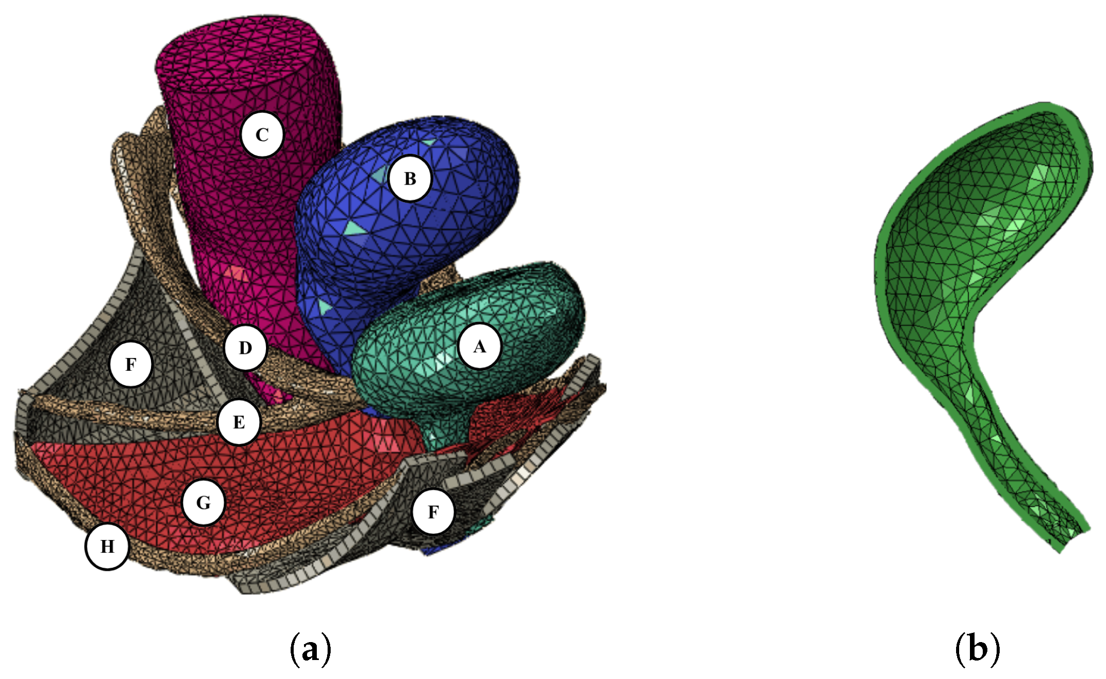
Figure 2.
(a) Sagittal and (b) axial views of MR images from a patient’s pelvic cavity with respective anatomical measurements: A) length. B) height, and C) width of the uterus.
Figure 2.
(a) Sagittal and (b) axial views of MR images from a patient’s pelvic cavity with respective anatomical measurements: A) length. B) height, and C) width of the uterus.
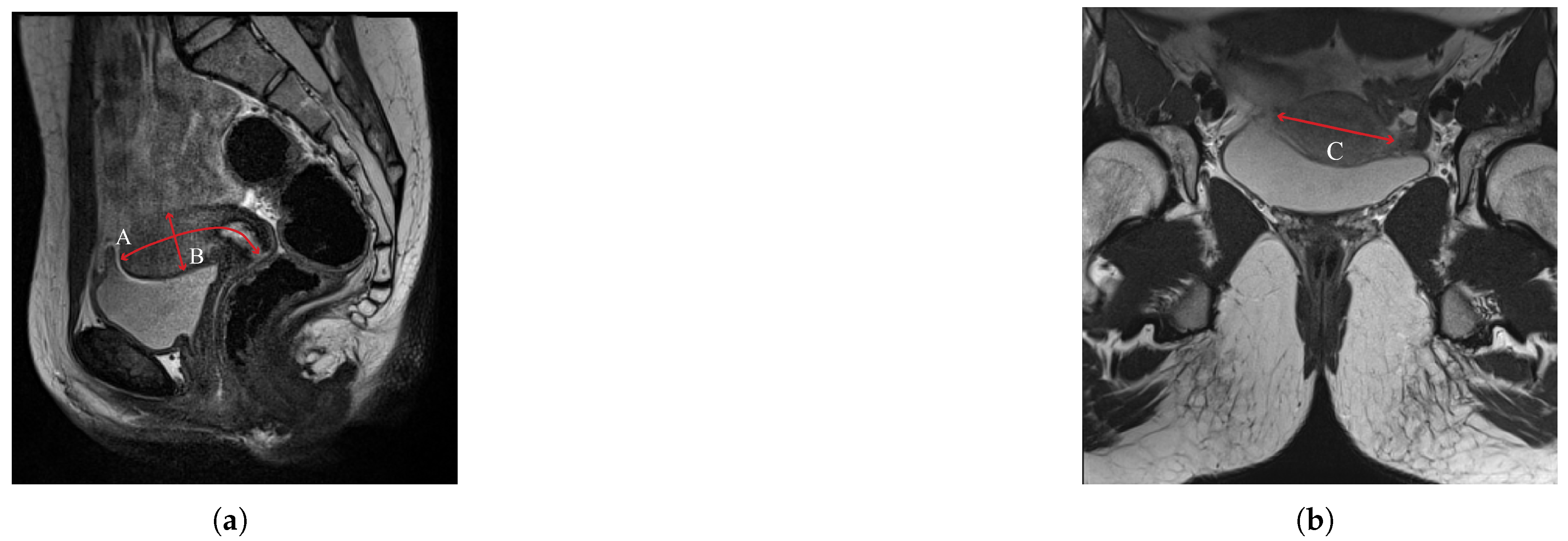
Figure 3.
(a) Sagittal and (b) axial views of the uterus and cervix. The parametric dimensions were established by [8], and applied to the images of the 20-year-old woman to build the new models.
Figure 3.
(a) Sagittal and (b) axial views of the uterus and cervix. The parametric dimensions were established by [8], and applied to the images of the 20-year-old woman to build the new models.
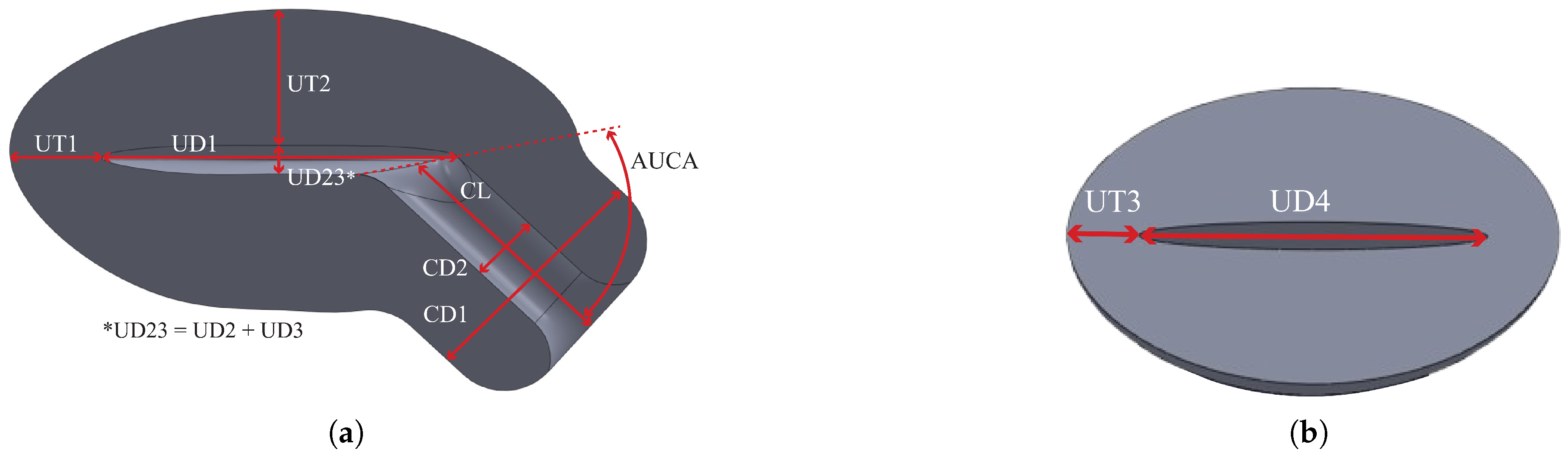
Figure 4.
Sagittal views of the a) patient-based and b) literature 3D geometric models of the uterus, cervix, and vagina.
Figure 4.
Sagittal views of the a) patient-based and b) literature 3D geometric models of the uterus, cervix, and vagina.
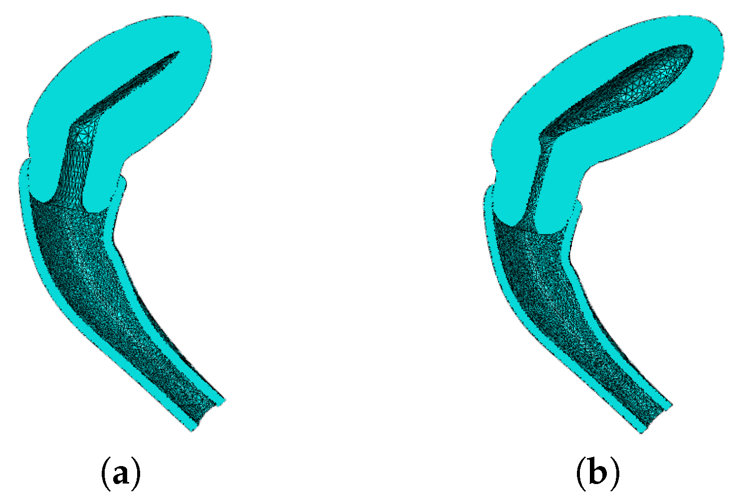
Figure 5.
Samples of ovine (a) vaginal, and (b) cervical tissues. (c) Stress-strain curves of human vaginal, and cervical tissues.
Figure 5.
Samples of ovine (a) vaginal, and (b) cervical tissues. (c) Stress-strain curves of human vaginal, and cervical tissues.
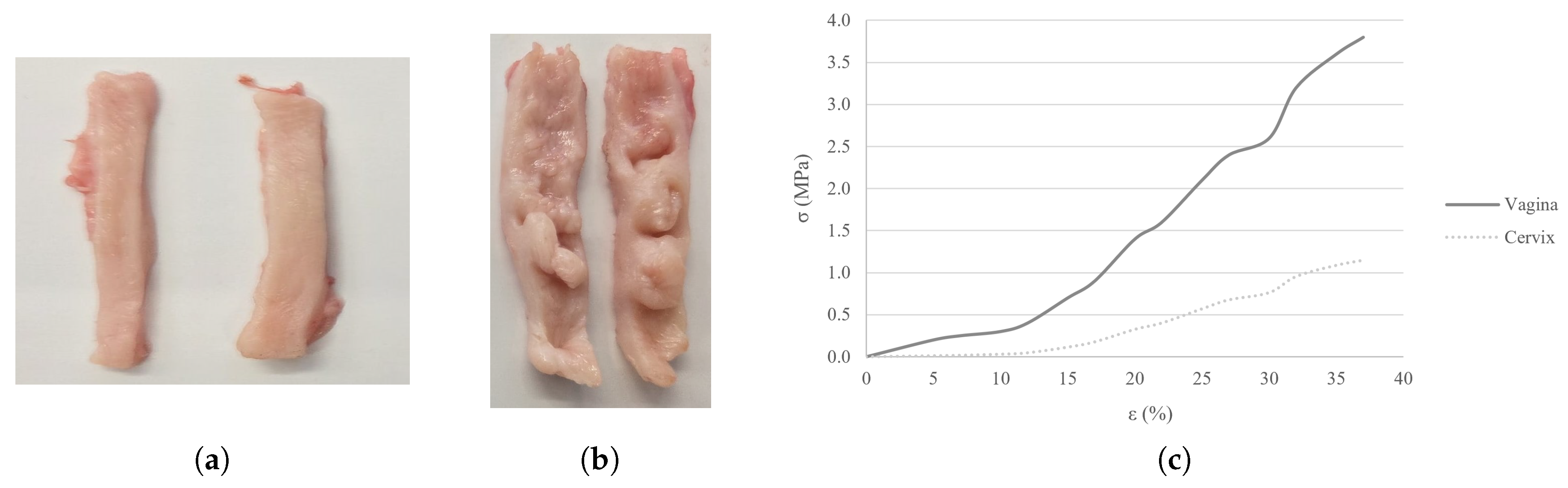
Figure 6.
Lateral view of the geometric models of the uterus, cervix, and vaginal canal of the BM, PM, and LM, with respective properties. The properties of the vagina and cervix are attributed to the yellow and white regions, respectively.
Figure 6.
Lateral view of the geometric models of the uterus, cervix, and vaginal canal of the BM, PM, and LM, with respective properties. The properties of the vagina and cervix are attributed to the yellow and white regions, respectively.
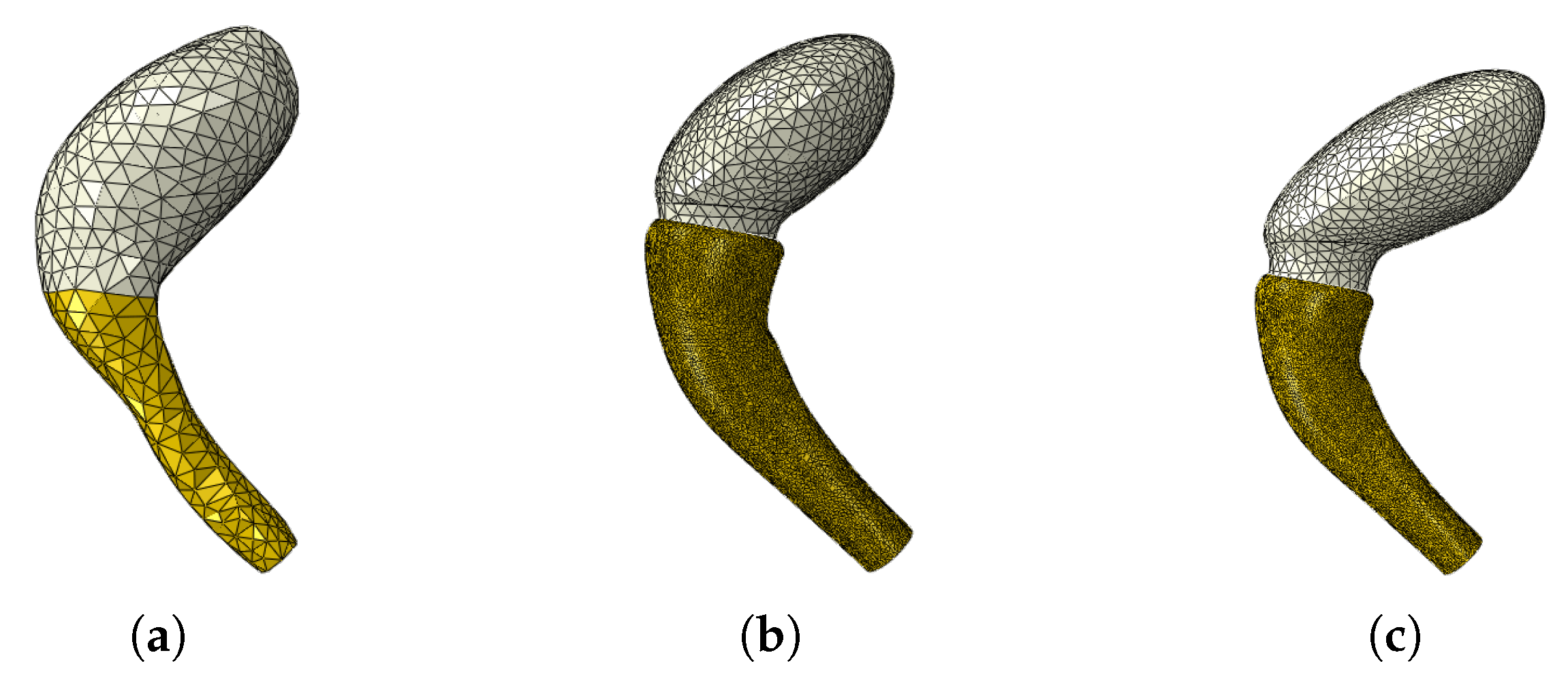
Figure 7.
Reference points for data extraction of the (a) CM uterus and vagina, uteri from the (b) PM and (c) LM, (d) bladder neck, (e) vaginal canal from the PM and LM, and (f) apical ligaments (USLs and CLs).
Figure 7.
Reference points for data extraction of the (a) CM uterus and vagina, uteri from the (b) PM and (c) LM, (d) bladder neck, (e) vaginal canal from the PM and LM, and (f) apical ligaments (USLs and CLs).
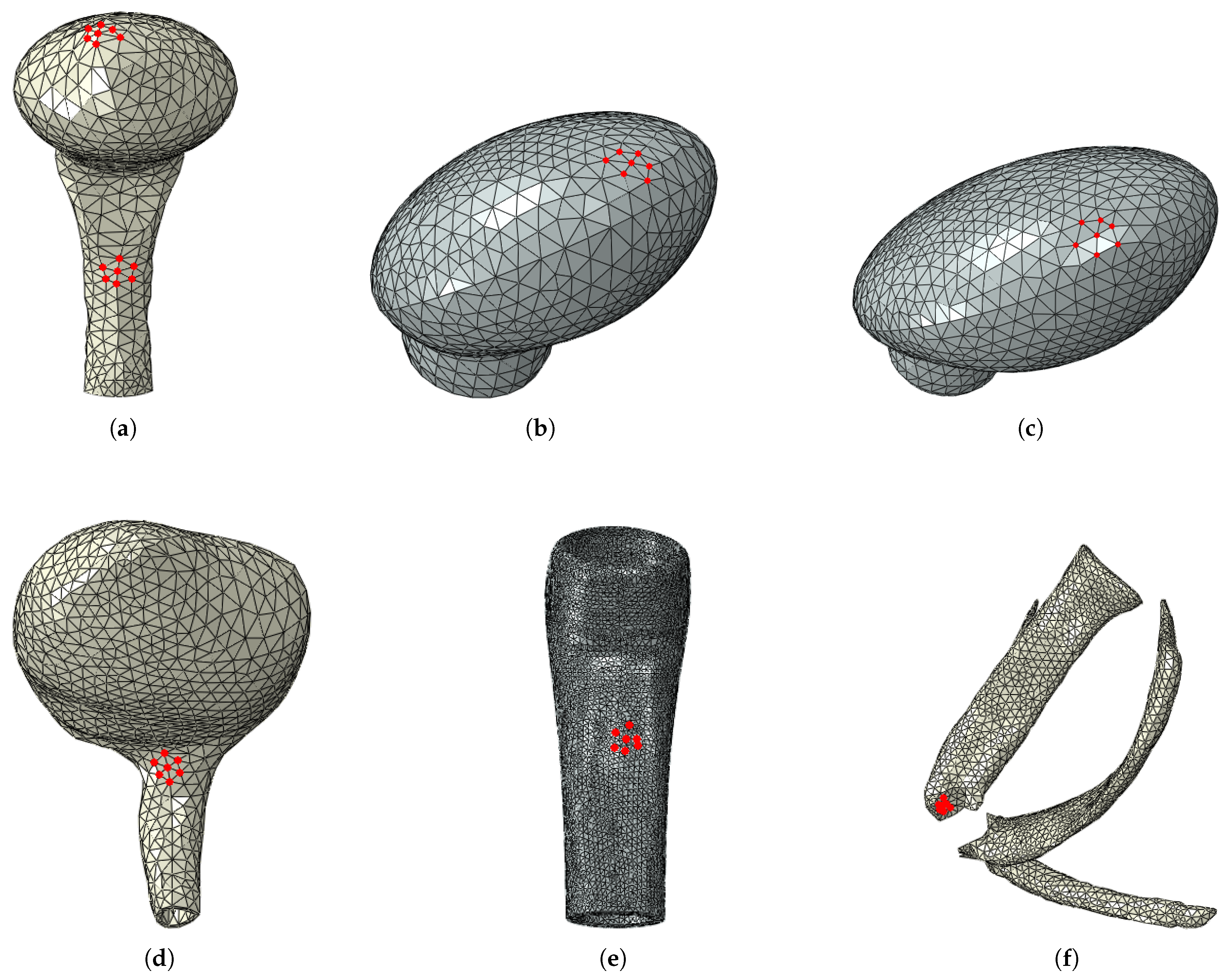
Figure 8.
Supero-inferior displacement at the final configuration of the (a) CM and (b) BM, and adjacent structures during the simulated Valsalva maneuver.
Figure 8.
Supero-inferior displacement at the final configuration of the (a) CM and (b) BM, and adjacent structures during the simulated Valsalva maneuver.
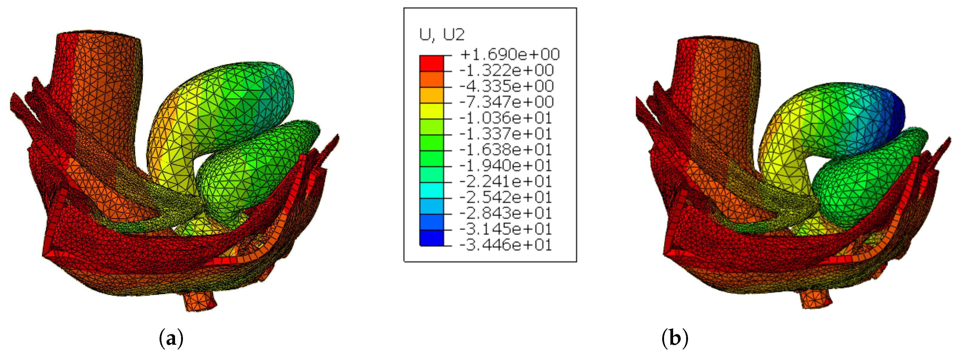
Figure 9.
Pressure vs Supero-inferior displacement curves of the selected reference nodes of the (a) uterus, (b) vagina, and (c) USLs for the CM and BM.
Figure 9.
Pressure vs Supero-inferior displacement curves of the selected reference nodes of the (a) uterus, (b) vagina, and (c) USLs for the CM and BM.
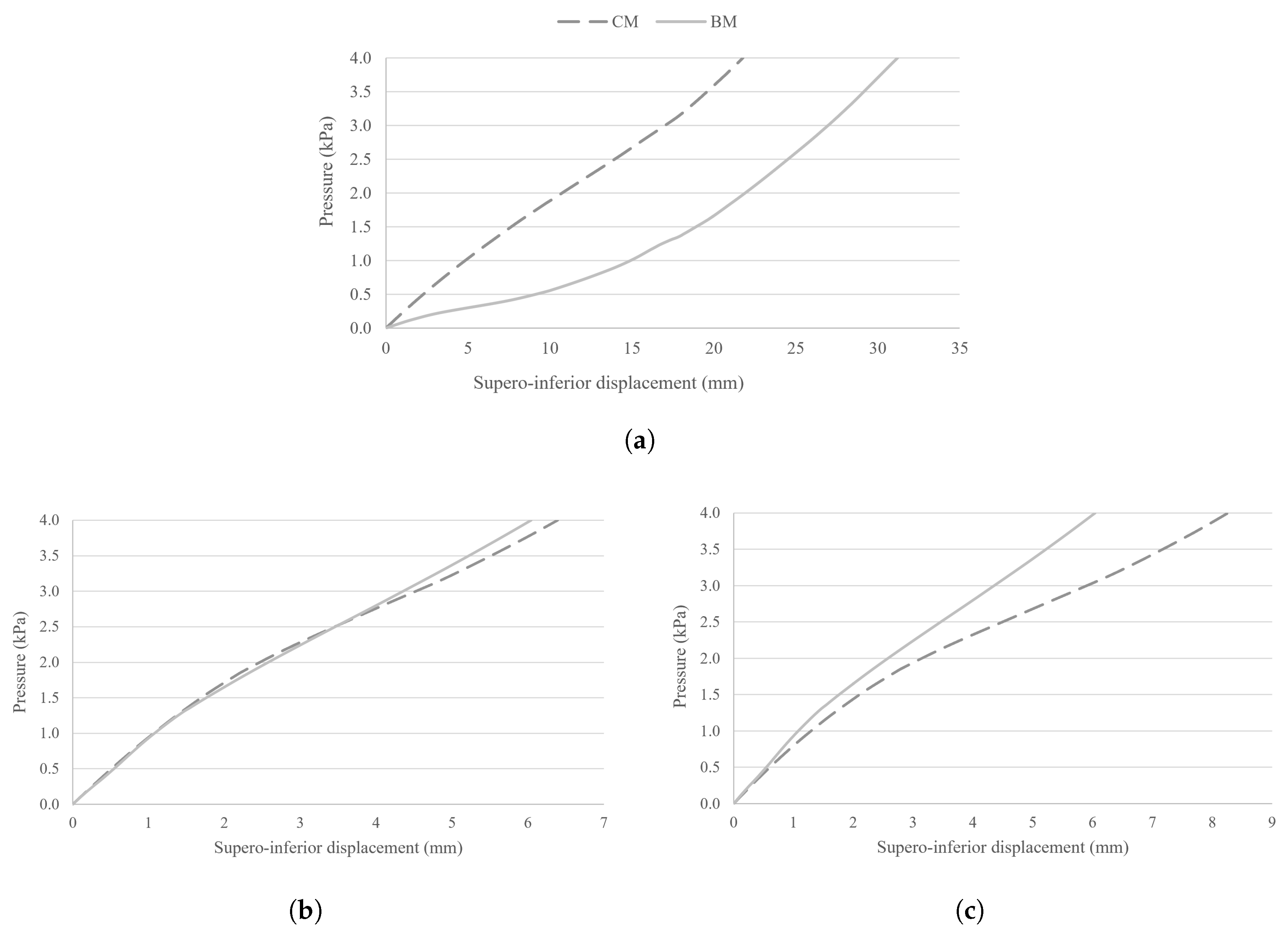
Figure 10.
Supero-inferior displacement at the final configuration of the (a) BM, (b) PM, and (c) LM with the new tissue properties during the simulated Valsalva maneuver.
Figure 10.
Supero-inferior displacement at the final configuration of the (a) BM, (b) PM, and (c) LM with the new tissue properties during the simulated Valsalva maneuver.
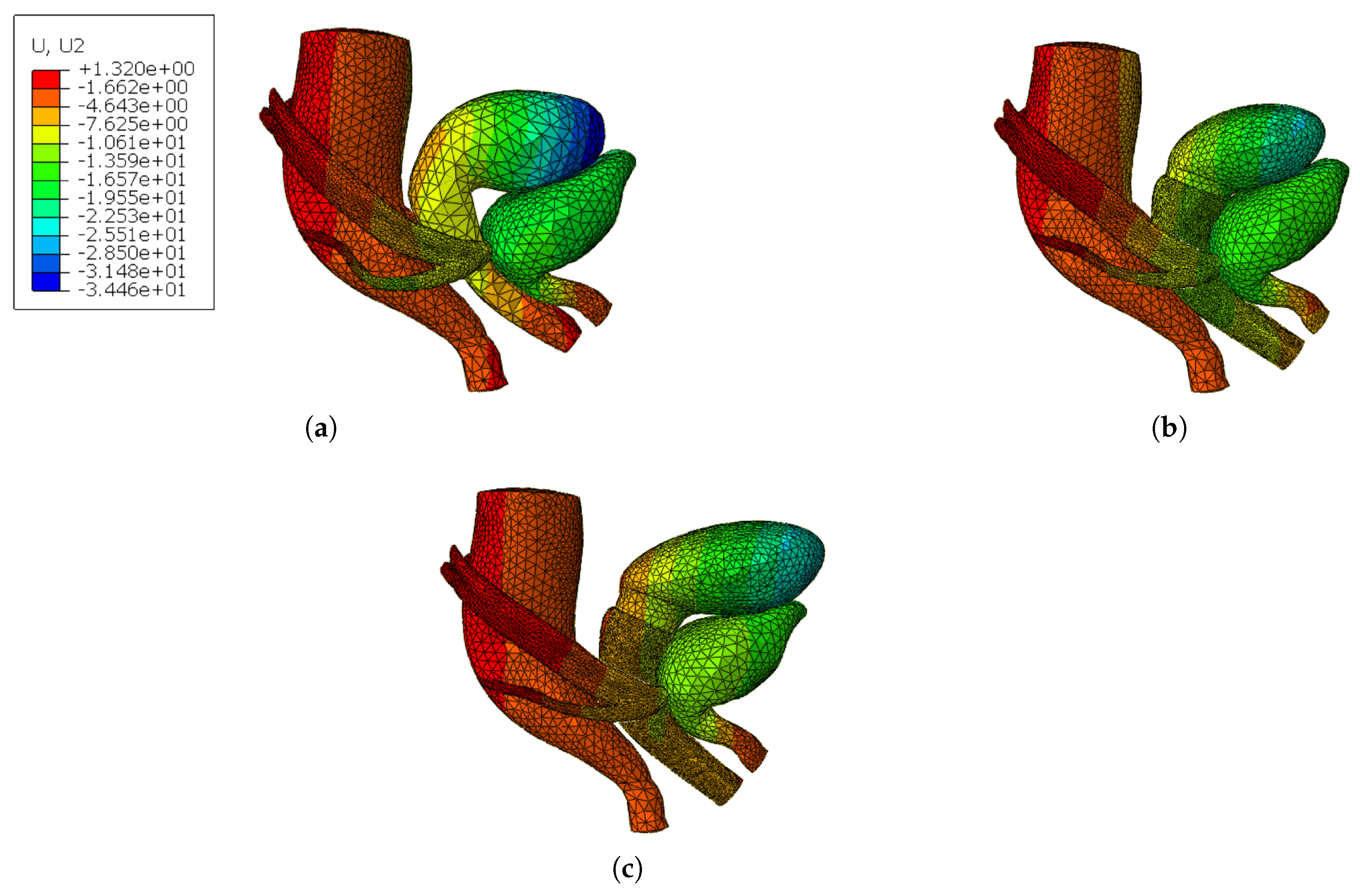
Figure 11.
Pressure vs Supero-inferior displacement curves of the selected reference nodes of the (a) uterus, (b) bladder neck, (c) vagina, and (d) USLs from the BM, PM, and LM.
Figure 11.
Pressure vs Supero-inferior displacement curves of the selected reference nodes of the (a) uterus, (b) bladder neck, (c) vagina, and (d) USLs from the BM, PM, and LM.
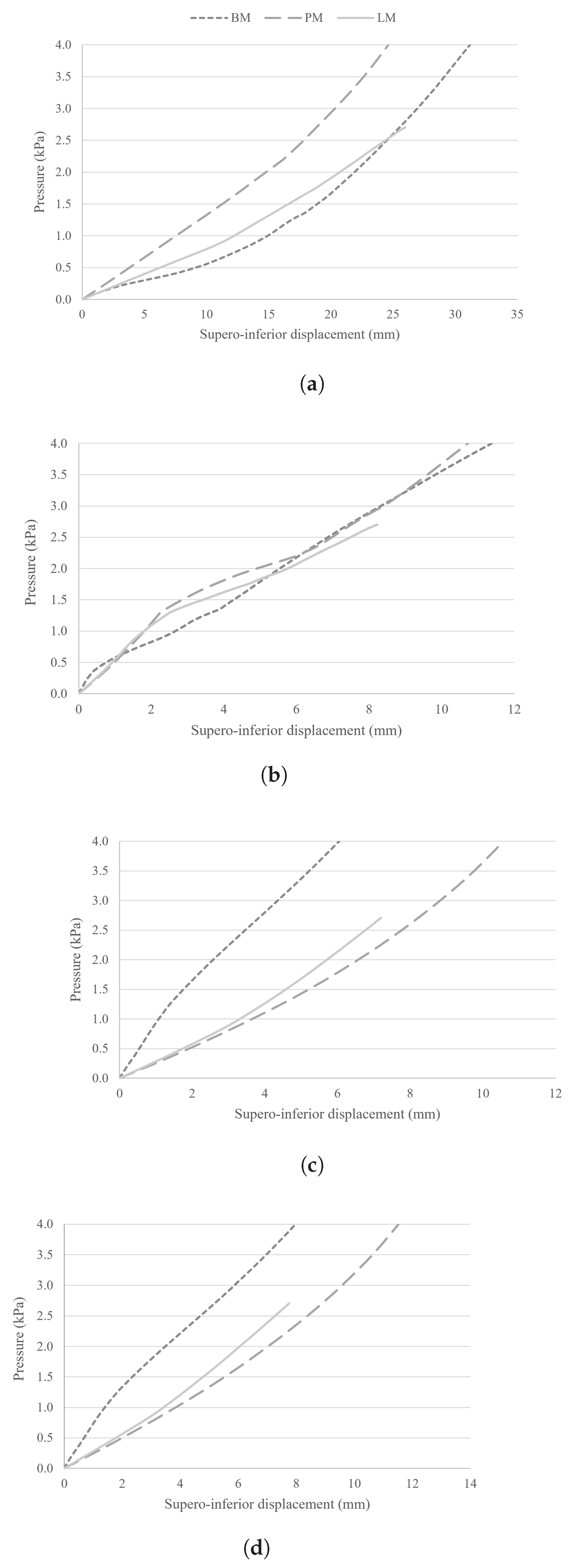

Table 1.
Geometric parameters of the uterus and cervix from the CM [18], and the new models (from the PM and LM) implemented in SolidWorks. The PM uses measurements from medical images, while the LM uses measurements from Louwagie et al. [19], and Chen et al. [20].
| Parameter (Unit) | CM | PM | LM |
|---|---|---|---|
| UT1 (mm) | 2.10 | 9.00 | 10.28 |
| UT2 (mm) | 2.10 | 13.16 | 12.80 |
| UT3 (mm) | 2.10 | 7.00 | 12.27 |
| UD1 (mm) | 65.21 | 34.00 | 55.00 |
| UD2 (mm) | 15.54 | 1.36 | 5.14 |
| UD3 (mm) | 15.54 | 1.36 | 5.14 |
| UD4 (mm) | 47.20 | 33.77 | 43.14 |
| AUCA (degrees) | - | 50.00 | 60.00 |
| CD1 (mm) | - | 23.40 | 26.00 |
| CD2 (mm) | - | 6.71 | 2.88 |
| CL (mm) | - | 13.31 | 30.15 |
Table 2.
Material parameters for hyperelastic models of the computational model.
| Ogden Hyperelastic Model | ||||
|---|---|---|---|---|
| Structure | (MPa) | Order |
Experimental data |
|
| Bladder and urethra | N=1 | [6] | ||
| Rectum | N=2 | |||
| Vagina, and uterus from the CM |
N=3 | |||
| Pelvic ligaments | N=1 | |||
| Cervix, and uterus from the BM, PM and LM |
N=3 | - | ||
| Yeoh Hyperelastic Model | ||||
| Structure | (MPa) | (MPa) | (MPa) |
Experimental data |
| Pubocervical fascia | 0.93 | -0.62 | 0.47 | [6] |
| ATFP, CLs, USLs | 1.74 | 6.60 | 4.79 | |
| PFMs | 0.003 | 0.002 | 0.001 | |
Disclaimer/Publisher’s Note: The statements, opinions and data contained in all publications are solely those of the individual author(s) and contributor(s) and not of MDPI and/or the editor(s). MDPI and/or the editor(s) disclaim responsibility for any injury to people or property resulting from any ideas, methods, instructions or products referred to in the content. |
© 2026 by the authors. Licensee MDPI, Basel, Switzerland. This article is an open access article distributed under the terms and conditions of the Creative Commons Attribution (CC BY) license.
Copyright: This open access article is published under a Creative Commons CC BY 4.0 license, which permit the free download, distribution, and reuse, provided that the author and preprint are cited in any reuse.