

Submitted:
11 October 2026
Posted:
13 October 2026
You are already at the latest version
Abstract
MYRRHA at SCK CEN in Mol/Belgium will be a pre-industrial large-scale Accelerator Driven System for unparalleled research opportunities in spent nuclear fuel treatment, nuclear medicine, and fundamental and applied physics. The Belgian government is funding MYRRHA’s first phase, MINERVA, for a staged implementation and operation. It covers the design, construction, and commissioning of the continuous wave superconducting RF, high power proton linac up to 100 MeV, as well as dedicated user target stations. The MINERVA proton linac will accommodate 30 identical cryomodules to boost the beam energy delivered by the normal-conducting frontend from 16.6 MeV to 100 MeV. Each cryomodule will contain two superconducting RF single-spoke cavities immersed in a superfluid Helium bath at 2 K. The design and architecture of the associated cryogenic system is derived from the stringent linac reliability requirements imposed by the future subcritical nuclear reactor. We present the resulting design basis, architecture, and detailed component design of the MINERVA Cryogenic System, the consolidation from prototype to series, and its current procurement and implementation status.
Keywords:
large-scale cryogenic system
; cryomodule
; particle accelerator cryogenics
; 2 K refrigeration
1. Introduction
MYRRHA at SCK CEN will be a demonstration facility of a pre-industrial Accelerator Driven System (ADS) that connects a 600 MeV continuous wave (CW) proton accelerator to a subcritical reactor core in order to pioneer a method for reducing nuclear waste (transmutation). The approach anticipates a dramatic reduction in the waste radio toxicity, decreasing its lifetime by a factor of 1000 and its volume by 100 [1].
The MYRRHA facility relies on a proton beam delivered by a CW linac to sustain the nuclear reaction, thus providing a fail-safe mechanism; if the accelerator halts, so does the nuclear reactor. However, unwarranted beam stops would lead to time-consuming restart cycles, and to thermal stresses in the reactor components. To mitigate this, the linac is designed to resolve beam trips within 3 seconds, imposing an exceptionally high reliability requirement to the particle accelerator. The accelerator shall limit any beam trip longer than 3 seconds to no more than 10 instances within a 90-day operational run, corresponding to a meantime between failures (MTBF) of over 250 h.
The MINERVA project is the first phase of MYRRHA with the primary objective to demonstrate the required reliability. It consists of one of the two injectors, the low beta section of the accelerator up to 100 MeV, as well as Application Centers serving as dedicated user target stations (Figure 1).
2. Superconducting RF Linac
The low beta section of the MINERVA accelerator comprises 60 identical superconducting radiofrequency (SRF) cavities in order to increase the beam energy from 16.6 MeV to 100 MeV across a span of 90 m (Table 1). The cavities operate in continuous wave (CW) at a nominal resonant frequency of 352.20 MHz. These cavities are single spoke cavities made of bulk niobium (Nb) and operate at a temperature of 2 K in a saturated bath of superfluid Helium (He II). All cavities are identical in design, and individually tested to achieve a peak field of 9.1 MV/m with an unloaded quality factor Q0 > 5.2e9. Their nominal accelerating RF field depends on their specific location along the accelerator, with a maximum nominal value of 7 MV/m (Section 5.1.3). The higher peak field margin of ~30% provides series redundancy for cavity fault compensation (Section 3.1). To streamline the overall design and implementation, all cavities are grouped in pairs within a total of 30 identical cryomodules [2,3].
The baseline linac configuration of 30 cryomodules (LINAC_30) serves as the benchmark for all dimensioning activities, including cost and schedule estimations. In addition, a staged installation scenario of 24 initial cryomodules (LINAC_24) is considered when defining the minimal operational conditions of the cryogenic system.
3. Design Basis
3.1. Design Constraints
The linac’s reliability requirement (MTBF > 250 h) extends directly to the overall cryogenic system. Additionally, thermal cycling of the machine shall be minimized to avoid fatigue of the accelerator components. Consequently, the system shall sustain uninterrupted refrigeration at thermal-shield temperature or colder for as long as practically possible, with a target duration of at least 5 consecutive years.
The cavities’ superconducting transition (~9.1 K) allows operation at 4 K or 2 K. An energy-efficiency trade-off analysis performed early in the project found 2 K to be the overall optimum for MINERVA, leading to the reduction of dynamic heat loads at the expense of additional capital cost and a worse coefficient of performance (COP). Moreover, cooling via a superfluid helium (He II) bath at 2 K suppresses microphonics arising from boiling liquid helium (He I) at 4 K.
Because the linac runs continuous wave, RF power is dissipated into the 2 K bath continuously rather than in pulses, resulting in a dynamic-to-static ratio of 2 K cryomodule heat loads near 1 (Section 5.1.3). This dynamic heat load couples back into the RF system, where bath pressure affects the cavities’ resonant frequency, which in turn affects their dissipated RF power, which in turn affects bath pressure. This effect is sharpened by the cavities' relatively narrow bandwidth of around 150 Hz, another consequence of the CW operation.
Reliability places a further demand on the regulation's transient stability: the system shall remain steady through heat-load transients triggered by fault compensation. Should a cavity fail and detune, other cavities will compensate by adjusting their own RF field, an effect that can range from the neighboring cavities only up to all cavities across the linac. This new operational point can push the RF-induced heat load of the compensating cavities well beyond their nominal values (Section 5.1.3). Fault compensation shall occur within the 3-second window allowed for beam-trip recovery, yet the cryogenic system's thermal inertia and relatively slow response time take substantially longer to reliably react to the new operating point.
There are also project specific constraints. The cryogenic system must first operate with only 24 of the eventual 30 cryomodules present, representing a minimum design configuration in terms of refrigeration needs. Radiation from beam operation inside the accelerator tunnel sets a total accumulated dose requirement over the facility’s envisaged 40-60 year lifetime: 1 MGy for the cryomodules themselves, and 20 kGy for other components such as the cryogenic distribution. Parts subject to regular in-situ replacement during maintenance can be exempt from this dose requirement.
3.2. Architectural Responses
Each cryomodule contains no active valves, and is paired with its own independently-controllable valve box (Section 4.2). This modularity is meant to isolate failures from the rest of the linac as well as to ease maintenance and replacement. This also simplifies the staged installation strategy of LINAC_24 and LINAC_30.
These units are served by a single shared distribution backbone. Supercritical helium is used for this long-distance supply to avoid the two-phase flow instabilities that liquid transport would introduce over such a distance [5]. Local expansion within each valve box then confines the low-pressure He II routing to a short run (Section 5.1.2). This results in He II being transported from the valve box to the cryomodule via a jumper connection, which requires very good thermal performance. The very-low-pressure return header collects mass flow from the highest-generating cryomodules last, closest to the cryoplant, minimizing the pressure drop along the header (Section 5.2).
Cooling within each cryomodule is split into three separate circuits: one for the cavity bath, one for the thermal shield, and one for the RF power coupler’s cold-to-warm transition (Section 5.1.2). Each circuit intercepts heat at its own temperature level.
Although the cryomodules’ operating points vary with their position along the linac (Section 5.1.3), every cryomodule and valve box is manufactured to an identical design (Section 4.2). This trades local over-provisioning for design and procurement simplicity and interchangeability across a series of thirty. Nonetheless, a significant over-instrumentation is foreseen at 3 individual locations to allow validation of process models as well as cross-checking against the standard devices, with a cost impact contained by limiting it to only a few instances.
All cryomodules are equipped with accurately controllable electrical heaters to generate dummy heat loads. These serve to prime the cryoplant ahead of the start of beam operation (Section 3.3), and to "mask" fast heat-load swings induced by the RF system during fault compensation. This method relies on the heaters' faster response time to compensate for the inherently slower mass-flow control loops.
3.3. Sizing Scenarios
2 K Operation (2K-OP) is the scenario in which the linac’s RF system is permitted to operate and beam is accelerated, adding a dynamic heat load on top of the cryomodules’ static load. This RF-induced contribution couples the cryogenic and RF systems via the bath-pressure/cavity-frequency feedback loop. Contrary to other (standby) scenarios, this is the one scenario that carries the stringent reliability requirements of the linac.
2 K Standby (2K-SB) has similar setpoints to 2K-OP, but carries static heat loads only and is not subject to the same stringent requirements. With no beam operation permitted, its mass-flow and control setpoints can run substantially more relaxed, tolerating operational adjustments that would be unacceptable during 2K-OP. The transition between the two scenarios passes through a dedicated priming state, 2K-RAMP, which raises the heat load to the operational level using dedicated electrical heaters before RF is switched on and takes over.
2K-SB is the default standby scenario. Other cold standby scenarios are foreseen at different temperature levels: 4 K Standby (4K-SB), 10 K Standby (10K-SB), and Thermal Shield Standby (TS-SB), allowing the system to dwell at those temperatures without a full warm-up and cooldown cycle. This is especially useful for longer stops, maintenance on the plant’s equipment, or as a fallback for recoverable failures (Section 5.3).
Within any scenario, required cooling capacity is defined as a range rather than a single figure. Two specific sizing points are then defined for the overall system design: a Design Point as the operational target within the 2K-OP scenario for the LINAC_30 configuration, and a Standby Point as the operability floor for 2K-SB/LINAC_24.
4. System Overview
This section translates the design basis into the resulting QSYS architecture, including its physical decomposition, cryogenic layout, and building arrangement.
4.1. Overarching Architecture
The MINERVA Cryogenic System (QSYS) can be physically decomposed into four main physical blocks. The first block are the cryomodules, with Helium being the sole cooling fluid. The cryomodules are the main cryogenic users, with the SRF cavities being the primary load. The second block is the Cryogenic Distribution Backbone (QDB), comprising transfer lines and distribution boxes used to deliver the cryogenic fluid to the end user. The third block is the Cryogenic Plant & Storage (QPS), as the industrial-size system comprising all the necessary equipment required by the thermodynamic cycle to produce the cryogenic cooling (cold/warm compressors, heat exchangers, expansion turbines, etc.) as well as storage systems for fluids. The fourth block is the Warm Piping System (WPS), referring to the collection of supporting systems such as warm general piping and warm transfer lines for purging and recovery.
4.2. Cryogenic Layout
The cryogenic layout of the SRF linac is composed as a sequence of 30 cavity cryomodules (QM) (Figure 2). Each cryomodule is connected to a dedicated cryogenic valve box (QVB). Together, each QM and its QVB form a cryogenic cell (QCELL) — a functional unit defining how a cryomodule and its valve box operate together as an independent cryogenic entity. Consequently, the QVB belongs to the QDB physically, but to the QCELL functionally. Each QCELL acts as a modular and largely independent unit capable of controlling its own flow by tapping from and returning to the cryogenic distribution headers in a modular fashion. Although all QCELLs are identical in design, their dynamic heat loads and corresponding mass flows will depend on their specific location along the linac, resulting in different operating points.
All QCELLs are served by the cryogenic headers within the Main Cryogenic Line (QLM), which originates at the cryoplant, enters the high energy side of the linac tunnel, and then connects to the last (30th) valve box of the linac. The header flows are then passed through each valve box in series, terminating at a return module called End Box (QVE) which manages the unused mass flow and helps regulating the headers pressure.
The Cryoplant (QPLANT) is situated nearby the linac tunnel to limit the pressure loss and static heat load along the QLM, which has a total length of ~54 meters including all bends and chicanes. The QPLANT will also include an additional dewar filling station for external users belonging to the Application Centers. The storage tanks are located next to the Cryoplant, comprising Warm Helium Gas storage (WSH) and eventually Liquid Nitrogen Storage (QSN) should the final system design require nitrogen pre-cooling. The cooling power required from the Cryoplant is estimated in the order of 3.3 kW equivalent at 4.5 K (with ~70% originating at 2 K isothermal). A preliminary design of the QPS is available in [6].
The WPS comprises four warm helium lines (W, U, S, V) running parallel to the QLM, providing the infrastructure for warm helium supply, recovery, and venting between the cryoplant and the cryogenic users.
4.3. Building Arrangement
The MINERVA Cryogenic System spans across multiple buildings (Figure 3). All 30 QCELLs and the unique End Box (QVE) will reside inside the tunnel of the SRF linac. A room within the Accelerator Utility Building (AUB) will house the Cold Box Station (QRB) including its respective warm panel. This room will also offer the possibility to fill to and from external liquid helium dewars. The Cryogenic Compressor Building (CCB), dedicated to the Warm Compressor Station (WCS), will contain the warm helium compressors, the oil removal system, and the gas storage management. Finally, the storage tanks will remain outside the main buildings at a designated storage area between the AUB and CCB buildings. Figure 4 depicts the equipment arrangement within the linac tunnel, particularly at the high energy end where the Main Cryogenic Line (QLM) interfaces with the final (30th) valve box of the SRF linac.
5. Subsystem Design
This section presents the detailed design of each QSYS subsystem. The individual designs reflect the current status and may evolve as procurement progresses (Section 7).
5.1. Cryogenic Cell (QCELL)
5.1.1. QCELL Description
Figure 5 shows the arrangement of QCELLs along the SRF linac for a sequence of two cryomodules with their respective valve boxes. The cryomodule is depicted with its internal components in Figure 6. Its architecture remains consistent with the prototype cryomodule presented previously in ref. [7,8,9]: a cryomodule cryostat containing a pair of SRF cavities, each of which with its own RF power coupler, tuning system, and magnetic shield. The design at the subcomponent-level has since been significantly redesigned (Section 6). Figure 6 reflects the consolidated design as it stands ahead of the contractor’s detailed manufacturing drawings.
Each QVB provides the physical interface between the QLM headers and the associated cryomodule. A jumper connects the QVB with the QM, and contains a vacuum barrier on the QVB side. Standardized Peripheral Modules (PeMo) are used throughout the system as modular sub-assemblies providing specialized functions such as flow control, pressure monitoring, and pressure relief (Section 5.2).
5.1.2. Cooling Circuits
Figure 7 illustrates the schematic cooling circuits within a QCELL as “seen” by the distribution system, and simplifies the heat loads as lump power depositions within a point-like geometry. The present configuration comprises three separate cooling circuits, each subject to its own cooling requirements and operating temperature. Each circuit branches from/into a header line: the four cold Headers A, B, D, and E interface with the QLM, while the warm Line W returns to the warm recovery system. The CAV Circuit (A–B) is specifically for the isothermal cooling of the SRF cavities at 2 K. The TS Circuit (D–E) actively cools the thermal shields and is also used for heat intercepts. The CPLR Circuit (A–W) has been designed to thermalise the RF power couplers.
Figure 8 presents a detailed QCELL process flow diagram (PFD), including secondary and tertiary circuit branches.
The CAV Circuit includes a subcooling heat exchanger that uses the returning 2 K saturated vapour (Header B) to cool the incoming supercritical helium (Header A) as far as possible while still at high pressure (~3 bar). The subcooled helium is then expanded through a Joule-Thomson valve to ~26 mbar, producing He II at ~2 K. Subcooling prior to expansion increases the liquid yield by reducing the flash fraction compared to expanding directly from 4.5 K, improving the efficiency of the 2 K cooling circuit. This circuit has headroom up to 3 g/s (~60 W cooling power) to avoid local bottlenecks and redirect cooling power to a QM when needed. The TS Circuit runs from Header D (~40 K, ~14 bar) to Header E (~60 K, ~13 bar), cooling the cryomodule’s thermal shield and heat intercepts. The CPLR Circuit draws from Header A (~4.5 K, ~3 bar) and thermalises each RF power coupler across its full cold-to-warm transition, from about 4 K up to 300 K, before discharging to the warm return Line W (~293 K, ~1.05 bar).
Secondary branches support the main circuits rather than extracting heat load. A Filling branch is used to cooldown and fill the cavity tanks directly from the bottom; it runs from Header A through a dedicated fill valve, with the helium returning via Header B. Pressure relief branches run along different paths. For example, routine relief is handled by a control valve connecting the buffer tank to the Safety Line (S), whereas a passive safety valve on the same buffer tank is used to discharge to the Vent Line (V) during worst-case safety events (Section 5.4).
Tertiary branches host ports for pressure sensors, local purging and conditioning, and the eventual use of RLC-modules for damping thermo-acoustic oscillations (TAOs).
5.1.3. Heat Loads and Cooling Capacity
Figure 9 shows each cavity’s nominal accelerating gradient (Eacc) as a function of position along the linac. This profile follows an S-shape, slowly rising over the first ~18 cavities, with a sharp increase across the middle cavities, and flattening afterwards. The cavities’ dissipated heat load (Pcav) scales with Eacc²/Q0. Therefore, a scaling factor alpha, defined as
is used throughout for reference values Pcav_ref = 4.25 W, Eacc_ref = 7 MV/m, and Q0 = Q0_ref = 5.2e9. This is an underlying methodology that mirrors the approach of other large-scale accelerator facilities [11]. A QM’s dynamic load is the sum of its two cavities’ scaled contributions.
α = Pcav/Pcav,ref = (Eacc/Eacc,ref)²,
Table 2 lists the revised cooling requirements as per our latest Heat Load Model (HLM v4.0) [12]. The values do not include contingency and differentiate between static and dynamic heat loads originating at the QCELLs. Static heat loads are heat in leaks coming from the surroundings via conduction or radiation, and depend on the cryostat design. Dynamic heat loads result from the power dissipated in the SRF cavities and the RF power couplers due to the changing electromagnetic fields. The RF loss of each cavity is computed individually as a function of its linac position, while the resistive loss of each RF power coupler is treated as an on/off contribution.
The updated values incorporate our latest return of experience and are the combination of multiple sources, such as past measurements from the MINERVA prototype cryomodule, calculations related to consolidated design features, heat load budgets allocated to elements still under manufacturing, and documented insights from similar systems [13].
Since Pcav ∝ 1/Q0, a significant uncertainty derives from the actual quality factor Q0 of the cavities once in operation. While the table assumes a constant Q0 of 5.2×10⁹ as per the requirements, each cavity is tested stand-alone to validate that its Q0 exceeds that value up to Eacc = 9.1 MV/m, and even targets Q0 > 6×10⁹ at Eacc = 11 MV/m as a manufacturing target. Therefore, the table values carry an implicit margin when cavities overperform. Additional heat loads from underperforming cavities are covered by the uncertainty and overcapacity margins introduced in Section 5.3, and can be locally absorbed by redirecting cooling capacity to a single QCELL.
5.2. Cryogenic Distribution Backbone (QDB)
The Cryogenic Distribution Backbone (QDB) comprises three main elements in series: the Main Cryogenic Line (QLM), a string of up to 30 Valve Boxes (QVB) corresponding to the baseline LINAC_30 configuration, and the End Box (QVE).
The QLM is a multi-stream cryogenic transfer line housing four main cold Headers (A, B, D, E), entering the linac tunnel through a chicane that provides radiation shielding. Table 3 summarises the nominal conditions of the four main headers at the QRB interface.
Header B operates at the lowest pressure of the four main headers and carries the most stringent pressure drop budget in order to preserve the maximum possible pressure at the cold compressor inlet. The cavity bath operates at the saturated vapour pressure of He II (~31 mbar at 2 K); the minimum pressure at any QVB position along Header B is set to ~27 mbar; and the nominal cold compressor inlet pressure at the QRB is defined at ~26 mbar. The 1 mbar allowance across the full QDB length is therefore the distribution share of this chain, with the remaining pressure drop occurring within the QCELL itself. Header B flows from the low-energy end of the linac toward the high-energy end and QRB. Since the high-energy QCELLs generate the largest return mass flows due to their higher RF loads, placing them closest to the QRB minimises the length over which the peak flows must travel, thereby reducing the overall pressure drop along Header B.
The static heat load budget (excl. contingency margins) per meter of QLM is ≤0.037 W/m on Header A, ≤0.12 W/m on Header B, ≤0.025 W/m on Header D, and ≤3.7 W/m on Header E. The tight budgets on Headers A and B are operationally critical: any additional heat load at these temperature levels (2–4.5 K) carries a high thermodynamic cost, directly increasing the refrigeration demand at the most expensive point of the cycle.
The QDB string terminates at the QVE on the low-energy end of the linac. The QVE caps the main headers, bypasses residual mass flows not consumed by the QCELLs during operation, and contributes to the regulation of header pressures across the distribution backbone.
Each QDB element — the QLM, every QVB, and the QVE — is equipped with a standardized set of Peripheral Modules (PeMos). PeMos are modular assemblies that provide the full service layer for cryogenic operation: flow measurement and control, pressure monitoring, pressure relief (both non-safety and safety-rated), helium guard supply, and instrument air distribution. Each PeMo type is defined once and replicated identically across all instances — the same pressure sensor module, the same safety relief module, and the same flow control module appear on every one of the QDB elements. This standardization reduces engineering effort, simplifies procurement, and enables consistent commissioning and maintenance across the series. The role of PeMo standardization in the broader implementation strategy is discussed further in Section 7.
The 3 over-instrumented QVBs will be located at the beginning, middle, and end of the accelerator. The additional instrumentation, a cold flowmeter and fast pressure sensors, feeds a digital twin of the cryogenic system. The digital twin tracks process drift over time, such as changes in valve permeability or abnormal RF-induced heat loads, and supports troubleshooting scenarios such as thermo-acoustic oscillations (TAO). The QDB includes provisions for convection brakes on large valves, thermal intercepts on large tertiary branches, and reserved installation space for RLC-modules.
5.3. Cryogenic Plant & Storage (QPS)
The QPS comprises a Warm Compressor Station (WCS) and a Refrigeration Cold Box (QRB) (Figure 10). The presented architecture reflects the preliminary design study conducted ahead of procurement [6].
The WCS operates across three pressure levels: a sub-atmospheric Very Low Pressure (VLP) level, a Low Pressure (LP) level around 1.05 bar, and a High Pressure (HP) level around 15 bar. The WCS water-cooling circuits are sized to recover up to 850 kW of waste heat for building heating, within a combined heat-sink capacity of 1300 kW.
Special provisions are put in place to preserve the helium inventory during a Loss of Offsite Power (LOOP) event. Up to 350 kW of back-up electrical power becomes available from an on-site diesel generator within 15–30 minutes to power one of the four HP compressors, hard-wired to that single unit, together with a matching back-up cooling-water capacity for that same compressor. Critical controls (HMI, PLCs, network, I/O) are held over by a UPS through the interruption, and the instrument-air network is backed up with ≥6 h of autonomy.
The QRB houses the main process heat exchangers, turbine expanders, cryogenic valves, and 80 K/20 K adsorbers, and precools the incoming helium from 300 K to 80 K using turbines; liquid nitrogen precooling remains an optional design variant. A train of cold compressors installed in the QRB pumps the return flow from the 2 K saturated He II baths down to approximately 26–30 mbar. Two helium phase separators complete the cold box: one at approximately 4.5 K/1.3 bar, which subcools the high-pressure supply feeding the QLM and serves the external dewar-filling station, and one near 2 K, used for cryoplant capacity testing and as a control reference for the cold compressors. The QRB interfaces with the QDB through the four cryogenic Headers A, B, D, and E.
The sub-atmospheric (VLP) compression stage must provide a compression ratio of approximately 40:1, from the ~26 mbar cold-compressor discharge to the ~1.05 bar LP level, together with a mass flow turndown of about 3:1 to accommodate the different operating modes. A hybrid compression scheme was selected: magnetic-bearing cold compressors within the QRB, in series with warm sub-atmospheric compressors in the WCS. Cold compression alone would recover the cold gas enthalpy efficiently but would offer limited turndown, whereas warm compression alone would give full flexibility at roughly twice the electrical consumption due to the lack of enthalpy recovery. In contrast, the chosen hybrid scheme combines the enthalpy recovery of the cold stage with the turndown flexibility of the warm stage. At least three warm VLP pumps operate in parallel; an installed spare unit is also under consideration.
The QPS design is specified for the Design and Standby Points listed in Table 4, corresponding to LINAC_30 at 2K-OP and LINAC_24 at 2K-SB respectively. The values already include standard uncertainty and overcapacity margins at the cryoplant’s interface, consistent with practice for systems of this scale [14,15,16]. The uncertainty margin applies 20% to static heat loads and 30% to dynamic heat loads. The overcapacity margin is applied per circuit: 20% on the CAV and CPLR circuits, 15% on the TS circuit.
The Warm Helium Storage (WSH) shall comprise at least three vertically-oriented storage vessels. Their final quantity and individual volume will be determined based on the final helium inventory. The current estimate totals around 485 kg (Table 5): 435 kg held by the Cryogenic Users, ~80% of it in the cryomodules alone, plus 50 kg for External Dewar Users. A contingency margin of at least 30% brings the storage tank capacity to around 630 kg. Storing the full helium inventory on site, together with this margin, reduces exposure to helium market supply constraints.
The QPS operates across a full sequence of scenarios spanning full shutdown to 2 K operation, from ambient standby (RT-SB, WSTOP) through partial cold standby (TS-SB, 10K-SB, 4K-SB, 2K-SB) to the 2K operating scenario (2K-OP). Figure 11 shows these states and their respective cooldown/warm-up transients. The 10 K Standby scenario (10K-SB) is used during QDB commissioning to ensure a “dry” helium supply (no liquid helium generation), and later during cavity cooldown to homogenize the temperature before turning superconducting, reducing the trapped magnetic flux induced by the Seebeck-effect, which would otherwise degrade the cavity quality factor Q0 [17]. The 4K Standby scenario (4K-SB) is used to save on electrical cost during long dwelling times and during the helium inventory transfer to and from the helium baths. The 2K ramping transient (2K-RAMP) is a bidirectional priming scenario for the controlled transitions between 2K-SB and 2K-OP.
5.4. Warm Piping System (WPS)
The WPS comprises the piping, valves, and instrumentation of the four warm helium lines (W, U, S, V). Lines S and V handle helium discharge during a relief event, Line W returns warm helium from the Cryogenic Users, and Line U supplies warm helium for purging, conditioning, and helium-guard replenishment. The typical flow conditions are listed in Table 6.
Line W collects the return flow from every CPLR circuit and sends it back to the QPS. Each coupler’s exhaust exits the tunnel individually via the service ducts and merges outside the tunnel into Line W at the AUB, keeping the line’s instrumentation and control valves outside the tunnel’s radiation environment throughout.
Line V is a set of venting lines to release helium to atmosphere at outdoor points. For the QMs, each 2K buffer tank is connected to independent venting lines, which exit the tunnel immediately and are sized for a sudden and total loss of beam vacuum. Additional venting lines are located at the Cold Box Room and other equipment.
Line S, by contrast, is an inventory-preservation path, returning helium discharges to the QPS rather than losing them to atmosphere. It is sized to accept the combined relief flow from across the system, aggregated up to a LOOP event. These discharges come from pressure relief valves (both passive and active) as well as from safety valves. It is separately protected against its own overpressure, venting to atmosphere in that case. For the QMs, each 2K buffer tank is connected to Line S for controlled pressure relief, thus minimizing the occasions where helium is discharged via Line V. Line S carries only clean helium, protecting any valve discharging into it from becoming a contamination pathway upstream.
Line U is sourced at the QPS and is primarily used for the replenishment of helium guards. It also serves as a source of clean helium, particularly for conditioning of individual QCELLs via capped ports.
6. Design Consolidation
The MINERVA prototype cryomodule was assembled and tested at IJCLab in Orsay, France, as part of an integrated prototyping strategy [18]. Two major test campaigns were conducted: the first on the empty cryostat, and the second on the fully equipped cryomodule including RF testing. Testing was accompanied throughout by a 1D digital twin model of the cryogenic process [19]. The prototype provided the primary empirical basis for a thorough design consolidation [12].
Significant design changes were implemented on the QM. The pipe cross-section between the cavity bath and the evaporating liquid surface was enlarged, raising the maximum heat flux through the bulk superfluid helium from 14 W to 25 W per cavity bath. The 2 K heat exchanger design used in the testing valve box was validated during the campaign and carries over unchanged to the series design. The RF power coupler’s cooling was redesigned from its original two-circuit configuration (4–10 K and 40–60 K) [20] to a single 4–300 K circuit per coupler, similar to [21]; this gives more stable operation at roughly half the cooling cost, and allows the suppression of return Header C (10 K, 1.3 bar) in favour of the warm return Header W.
Further design changes addressed structural and reliability findings. Cavity support moved from a table-based system to a tie-rod system [22], and the cryomodule cryostat received a full thermo-mechanical redesign. Reliability issues observed in the cold tuning system [23,24] motivated the development of a warm motor implementation for the tuner.
Due to the re-design efforts, the heat load values have yet to be empirically validated for the consolidated design. Consequently, sizing currently relies on budgeted figures, to be verified during the QM’s pre-qualification campaign.
7. Implementation
The overall procurement, production, and acceptance testing follow practices established by comparable large-scale SRF facilities [14], adapted to MINERVA's own component lifecycle, procurement structure, and technical requirements.
7.1. Procurement Philosophy
The public procurement of each component is launched at different stages of its design lifecycle, thus ensuring a balance between supplier input and design control. Design involvement is higher where a subsystem’s design is closely tied to the linac’s own requirements, and lower where the underlying engineering is already mature and standardized in industry.
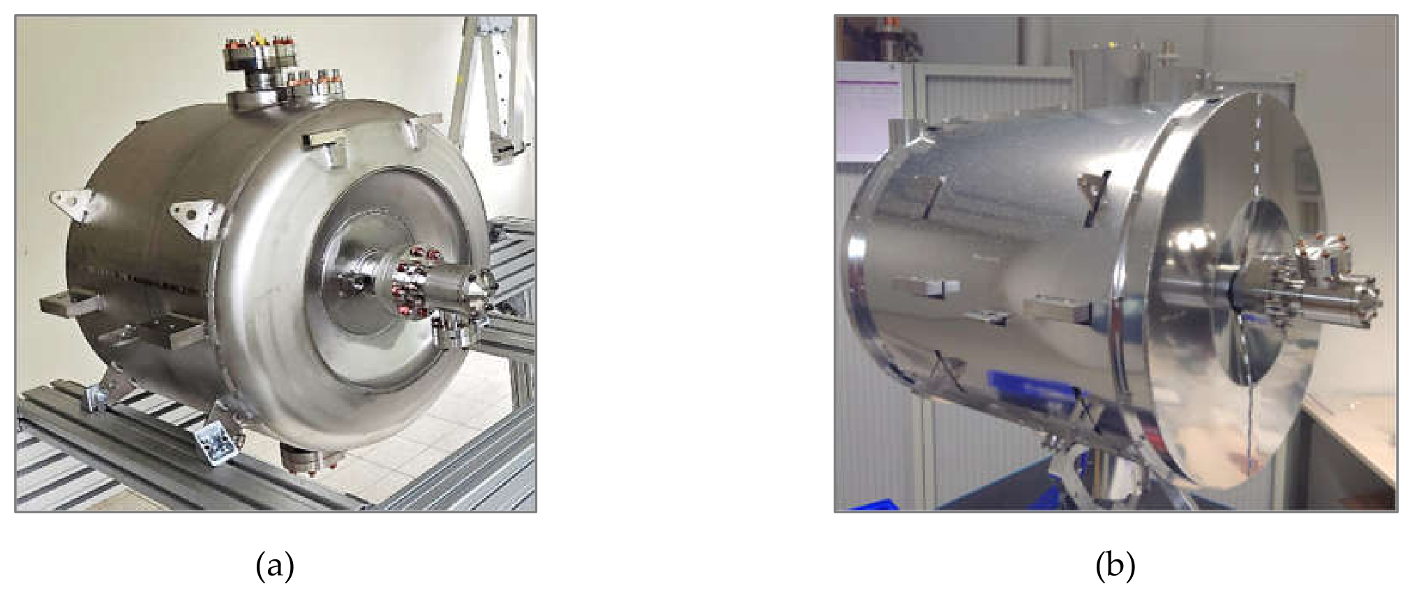
For the QM components (cavity, RF power coupler, tuning system, magnetic shield, cryostat, and their assembly), SCK CEN carries the full design responsibility up to the detailed CAD model, with the contractor manufacturing to this design and proposing modifications where manufacturability warrants. All cryomodule component contracts have been awarded. Research Instruments (Germany) holds four contracts: the SRF cavities, RF power couplers, cryostat, and cryomodule assembly. Meca Magnetic (France) supplies the magnetic shields, and AMOS (Belgium) the cold tuning systems. Mechanical construction of all series cavities [25] is now complete; qualification testing at FREIA is still ongoing (Figure 12). The cryostat's manufacturing drawings are under preparation, and the cryomodule assembly tools and procedures are being established.
The QDB follows an intermediate approach. The tight QDB integration with the rest of the facility ties many of its design choices back to facility-wide considerations. Therefore, SCK CEN defines the process design (heat load budgets, flow parameters) through detailed process flow and instrumentation diagrams, and hands over the mechanical design and implementation to the contractor. Nevertheless, SCK CEN remains especially involved throughout the entire Engineering Phase to ensure correct interpretation of the design intent. The QDB procurement process is currently ongoing.
For the QPS, SCK CEN specifies functional requirements based on the linac’s refrigeration needs and operating scenarios. The applicants then propose their own technical solution as part of their offer, and the contractor implements this design up to installation and stand-alone commissioning. The QPS’s integration into the overall cryogenic system is then led by SCK CEN. The QPS procurement process is ongoing.
7.2. Pre-Series and Series Production
Procurement of cryomodule components spans pre-series and series batches. The pre-series quantity is sized for around three complete sets of cryomodules, providing a testbed to validate the manufacturing process before committing to the full series. Schedule constraints may result in the individually qualified components entering series production before the qualification of the fully assembled cryomodule itself. For the QVB, the validation path allows a single pre-series unit, with successful qualification allowing direct entry into series production.
Series production is also applied to the Peripheral Modules. Each module type follows a single design reused identically across the entire QDB, reducing procurement scope and giving consistent assembly and commissioning across the series.
7.3. Acceptance Testing
Acceptance testing is distributed across dedicated facilities, reflecting each one’s specialized testing requirements.
Acceptance testing starts at the component level: the cavities together with their series magnetic shields are being tested at 2 K in the horizontal test cryostat, HNOSS, of the FREIA Laboratory (Uppsala University, Sweden). The multipacting is being conditioned, and Q0 and the field emission level are being characterized up to the contractual limit of 11 MV/m when achievable. The RF power couplers are conditioned at IJCLab (Paris-Saclay, France) at power levels similar to operation. The cold tuning systems are being qualified in performance and durability also at IJCLab, where a new test cryostat has been built for the redesigned warm-motor tuner.
The fully assembled QM is tested as a system at FREIA for design validation and acceptance testing. The main objectives are the validation of redesigned features and the QM pre-qualification prior to installation in the tunnel. This constitutes the QM's Site Acceptance Test (SAT), performed by SCK CEN independently of the QM contractor. An early characterization of the overall test setup is also foreseen. Therefore, all testing conditions and equipment are designed to be as close as reasonably possible to the final system, in order to qualify in the most representative conditions; this includes sub-systems such as LLRF, cryogenics, vacuum, utilities, and controls. The test stand is being set up with new equipment installed as it becomes available. A new test valve box has been designed specifically to fit the cryomodules to FREIA's infrastructure and is part of the QDB procurement scope. It will already feature the same control valves and instrumentation used in the linac tunnel. It will also be equipped with a flow conditioning unit to convert FREIA's liquefier supply (~1 bar) into a supercritical helium flow for cooling the CPLR circuit under representative conditions. Additional instrumentation is also foreseen to characterize the very-low-pressure helium return flow from the QM to the subcooling heat exchanger.
For the QPS and QDB, the Site Acceptance Tests will be carried out after installation in the MINERVA site. The QPS will be tested as a stand-alone system before it is further integrated. The QDB will be tested in two stages: first as a stand-alone system at room temperature, and then as an integrated system at cryogenic temperatures.
8. Conclusion
The MINERVA Cryogenic System is a large-scale refrigeration system for MYRRHA's superconducting proton linac. Its design basis, architecture, and detailed component design were developed as a single coherent system rather than as a collection of independent subsystems. Given the system's broad scope, this development strongly capitalized on the return of experience from comparable large accelerator facilities. The linac's reliability requirements and operational concept, derived from its direct coupling to a subcritical nuclear reactor, cascaded through the entire process at every level, from the modular system architecture down to circuit sizing and instrumentation standardization.
Consolidating such a design for series production requires weighing reliability, performance, and manufacturability together, on top of the already challenging cryogenic engineering of a complex, multidisciplinary system. For MINERVA, this weighing is reflected in the resulting changes to the cavity's cooling, support, and tuning systems, whose heat loads remain to be empirically validated pending the cryomodule's pre-qualification campaign.
A balance between design control and supplier input has proven crucial to implementation, and needs to be tailored and continuously adjusted according to each subsystem's reality. For MINERVA, design control is retained where it matters most for reliability and where system integration runs deepest, while more mature engineering is entrusted to specialized industrial partners, from the cryomodule's fully owned design, now in series production, to the cryoplant's procurement based on functional requirements. Delivering 30 identical, interchangeable cryomodules further demands standardization, de-risking via pre-series batches, and a qualification campaign distributed across multiple specialized facilities.
The evolution of the MINERVA Cryogenic System showcases the lifecycle of a large-scale cryogenic system, from first-principles design basis through to industrial-scale implementation.
Acknowledgments
This work is supported by the MYRRHA programme at SCK CEN (Belgium). The authors thank IJCLab (France), ACS (France), CEA/DSBT (France), and Uppsala University/FREIA (Sweden) for their collaboration throughout different phases of the project. The authors also thank their colleagues at ESS, CERN (LHC), DESY (European X-FEL), GANIL (SPIRAL2), SLAC (LCLS-II), and Fermilab (PIP-II) for their valuable input and discussions.
References
- Abderrahim, H.A.; et al. MYRRHA: A European Experimental ADS for R&D Applications Status at Mid-2005 and Prospective towards Implementation. J. Nucl. Sci. Technol. 2007, 44, 491–498. [Google Scholar] [CrossRef]
- Dorda, U.; Fabich, A. Implementation Update of MYRRHA Phase 1 (MINERVA). In Proceedings of the 17th International Particle Accelerator Conference (IPAC'26), Deauville, France, 17–22 May 2026; p. THP4014. [Google Scholar] [CrossRef]
- Dorda, U.; et al. Optimized Beam Optics Design of the MINERVA/MYRRHA Superconducting Proton Linac. In Proceedings of the 31st International Linear Accelerator Conference (LINAC'22), Liverpool, United Kingdom, 28 August–2 September 2022; p. paper TUPOJO03. [Google Scholar] [CrossRef]
- De Florio, V. SCK CEN Document ID 3703847, Rev. 1.0; De Florio, V. MINERVA 100 MeV Accelerator Technical Design Report; SCK CEN Document ID 3703847, Rev. 1.0; SCK CEN: Mol, Belgium, 2021. (Restricted). (Restricted); SCK CEN: Mol, Belgium, 2021.
- Cryogenic Helium Refrigeration for Middle and Large Powers. [CrossRef]
- Michel, F.; Berkowitz Zamora, D.; Bonne, F.; Bonthuys, G.; Millet, F.; Poncet, J.M. Preliminary studies of the MINERVA cryogenic supply system. IOP Conf. Ser. Mater. Sci. Eng. 2024, 1301, 012115. [Google Scholar] [CrossRef]
- Saugnac, H.; et al. The MYRRHA Spoke Cryomodule. In Proceedings of the 27th International Linear Accelerator Conference (LINAC'14), Geneva, Switzerland, August 2014; paper TUPP082, pp. 613–615. [Google Scholar]
- MAX – MYRRHA Accelerator eXperiment, Research and Development Programme; Project ID 269565; European Commission: Brussels, Belgium, 2011–2014; Available online: https://cordis.europa.eu/project/id/269565/reporting (accessed on 1 September 2026).
- Saugnac, H.; Blivet, S.; Gandolf, N.; Joly, C.; Kaabi, W.; Lesrel, J.; Longuevergne, D.; Olivier, G.; Pierens, M.; Sarlin, W.; Baylac, M.A.; Bondoux, D.; Bouly, F.; Dumont, P.-O.; Gómez Martínez, Y. Spoke Cryomodule Prototyping for the MINERVA Project. In Proceedings of the 19th International Conference on RF Superconductivity (SRF'19), paper MOP098. Dresden, Germany, 30 June–5 July 2019. [Google Scholar] [CrossRef]
- Vandersteen, G. The MINERVA Cryomodule; Version 7; CAD v.A44; SCK CEN Document ID 87760274; SCK CEN: Mol, Belgium. (Internal document).
- Berkowitz Zamora, D.; Claudet, S.; Perin, A. Refrigeration assessment of the existing cryogenic plants for the high luminosity upgrade of the Large Hadron Collider (LHC). IOP Conf. Ser. Mater. Sci. Eng. 2017, 278, 012099. [Google Scholar] [CrossRef]
- Berkowitz Zamora, D.; Bonthuys, G.; Dekhtiarov, V.; Dorda, U.; Marhauser, F.; Michel, F.; Bonne, F.; Millet, F.; Poncet, J.M.; Saugnac, H.; Joly, C.; Olivier, G.; Lhomme, C.; Junquera, T.; Dieudegard, F.; Beniken, M.E.A.; Tijani, Y.; Thermeau, J.P. Status of the MINERVA cryomodules and associated cryogenic system (MYRRHA phase 1). IOP Conf. Ser. Mater. Sci. Eng. 2024, 1301, 012104. [Google Scholar] [CrossRef]
- Maiano, C.G. Production, Test and Installation of the ESS Spoke, Medium and High Beta Cryomodules. In Proceedings of the 31st International Linear Accelerator Conference (LINAC'22), Liverpool, United Kingdom, 28 August–2 September 2022; paper TH1PA02, pp. 685–690. [Google Scholar] [CrossRef]
- Weisend, J.G. Cryogenic Technologies at the European Spallation Source: A Big Science Case Study; IOP Publishing: Bristol, UK, 2024. [Google Scholar] [CrossRef]
- Claudet, S.; Lebrun, P.; Serio, L.; Tavian, L.; van Weelderen, R.; Wagner, U. Cryogenic Heat Load and Refrigeration Capacity Management at the Large Hadron Collider (LHC). In Proceedings of the 22nd International Cryogenic Engineering Conference (ICEC22)/International Cryogenic Materials Conference (ICMC 2008), Seoul, Republic of Korea, 21–25 July 2008; pp. 835–840. (CERN Report No. LHC-Project- Report-1171).
- Gahier, V.; Brodzinski, K.; Claudet, S.; Delprat, L.; Lees, A.; Monneret, E.; Perin, A.; Sisti, M.; Van Weelderen, R. Cryogenic architecture and heat loads for the High-Luminosity upgrade of the Large Hadron Collider. IOP Conf. Ser. Mater. Sci. Eng. 2025, 1327, 012003. [Google Scholar] [CrossRef]
- Vogt, J.-M.; Kugeler, O.; Knobloch, J. Impact of cool-down conditions at Tc on the superconducting rf cavity quality factor. Phys. Rev. ST Accel. Beams 2013, 16, 102002. [Google Scholar] [CrossRef]
- Vandeplassche, D.; Belmans, J.; Angulo, C.; Davin, D.; De Cock, W.; Della Faille, P.; Doucet, F.; Gatera, A.; Pompon, F.F.; Bondoux, D.; Bouly, F.; Höltermann, H.; Mäder, D.; Joly, C.; Olry, G.; Saugnac, H.; Loiselet, M.; Postiau, N.; Standaert, L.; Podlech, H.; Ratzinger, U. Integrated Prototyping in View of the 100 MeV Linac for Myrrha Phase 1. In Proceedings of the 9th International Particle Accelerator Conference (IPAC'18), Vancouver, BC, Canada, 29 April–4 May 2018; paper TUPAF003, pp. 661–664. [Google Scholar] [CrossRef]
- Lhomme, C.; Berkowitz Zamora, D.; Grosso Xavier, M.D.; Chatelet, F.; Duthil, P.; Saugnac, H.; Dieudegard, F.; Junquera, T. An Approach for Component-Level Analysis of Cryogenic Process in Superconducting LINAC Cryomodules. In Proceedings of the 31st International Linear Accelerator Conference (LINAC'22), Liverpool, United Kingdom, 28 August–2 September 2022; paper TUPOGE04, pp. 487–490. [Google Scholar] [CrossRef]
- Gómez Martínez, Y.; Baylac, M.A.; Bondoux, D.; Bouly, F.; Dumont, P.-O.; Blivet, S.; Joly, C.; Lesrel, J.; Saugnac, H.; Kaabi, W. MYRRHA 80 kW CW RF Coupler Design. In Proceedings of the 10th International Particle Accelerator Conference (IPAC'19), Melbourne, Australia, 19–24 May 2019; paper THPTS007, pp. 4115–4117. [Google Scholar] [CrossRef]
- Arcambal, C.; et al. Status of the Power Couplers for the ESS Elliptical Cavity Prototypes. In Proceedings of the 17th International Conference on RF Superconductivity (SRF'15), Whistler, BC, Canada, 13–18 September 2015; paper THPB078, pp. 1309–1312. [Google Scholar]
- Reynet, D.; Brault, S.; Duthil, P.; Duchesne, P.; Olry, G.; Rampnoux, E.; Bousson, S. Design of the ESS Spoke Cryomodule. In Proceedings of the 16th International Conference on RF Superconductivity (SRF'13), Paris, France, 22–27 September 2013; paper MOP089, pp. 357–360. [Google Scholar]
- Gandolfo, N.; Blivet, S.; Chatelet, F.; Delpech, V.; Le Dréan, D.; Mavilla, G.; Pierens, M.; Saugnac, H. Accelerated Lifetime Test of Spoke Cavity Cold Tuning Systems for Myrrha. In Proceedings of the 31st International Linear Accelerator Conference (LINAC'22), Liverpool, United Kingdom, 28 August–2 September 2022; paper TUPOJO23, pp. 406–409. [Google Scholar] [CrossRef]
- Santiago Kern, R.; Fransson, K.; Gajewski, K.J.; Hermansson, L.; Li, H.; Lofnes, T.; Miyazaki, A.; Olvegård, M.; Profatilova, I.P.; Ruber, R.J.M.Y.; Svanberg, C.D.I.; Zhovner, M. Completion of Testing Series Doublespoke Cavity Cryomodules for ESS. In Proceedings of the 21st International Conference on RF Superconductivity (SRF'23), Grand Rapids, MI, USA, 25–30 June 2023; paper THIAA03. [CrossRef]
- Moretti, M.; Hoerstensmeyer, Y.N.; Navitski, A.; Marhauser, F. Fabrication and Surface Treatment of Superconducting RF Single Spoke Cavities for the Myrrha Project. In Proceedings of the 21st International Conference on RF Superconductivity (SRF'23), Grand Rapids, MI, USA, 25–30 June 2023; p. paper TUPTB067. [Google Scholar] [CrossRef]
Figure 1.
The MINERVA Accelerator Facility as the 1st phase of the MYRRHA Program. [1].
Figure 1.
The MINERVA Accelerator Facility as the 1st phase of the MYRRHA Program. [1].
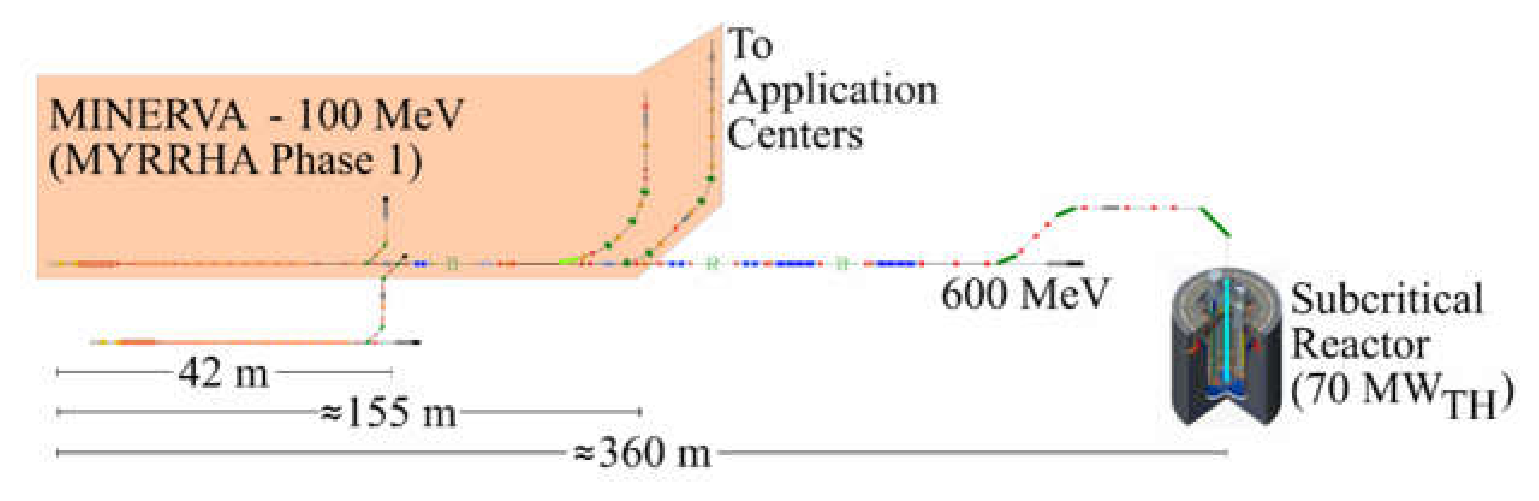
Figure 2.
The SRF linac and associated cryogenic system.
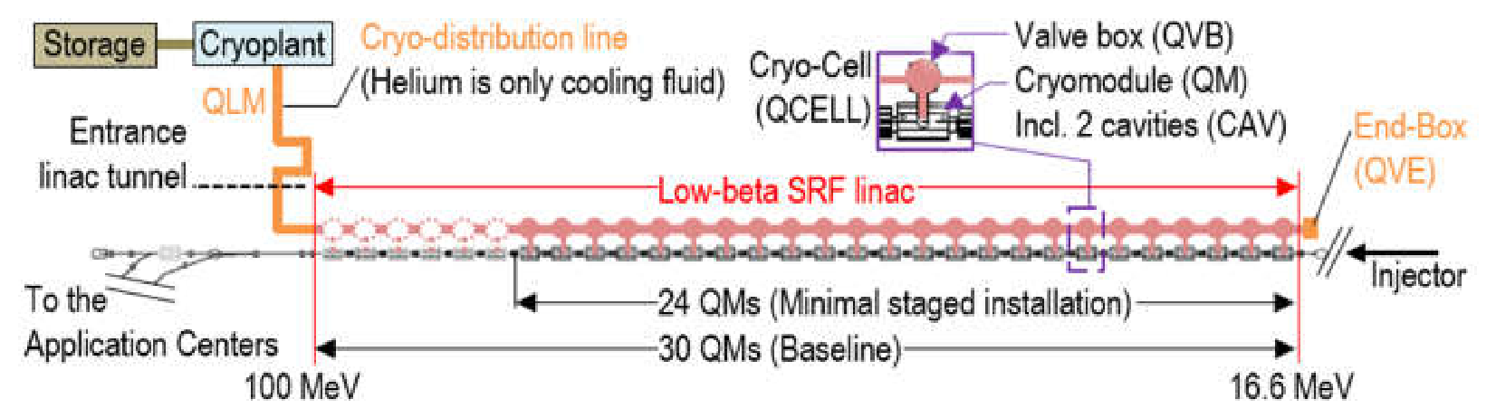
Figure 3.
Space dedicated to the cryogenic system (dashed area).
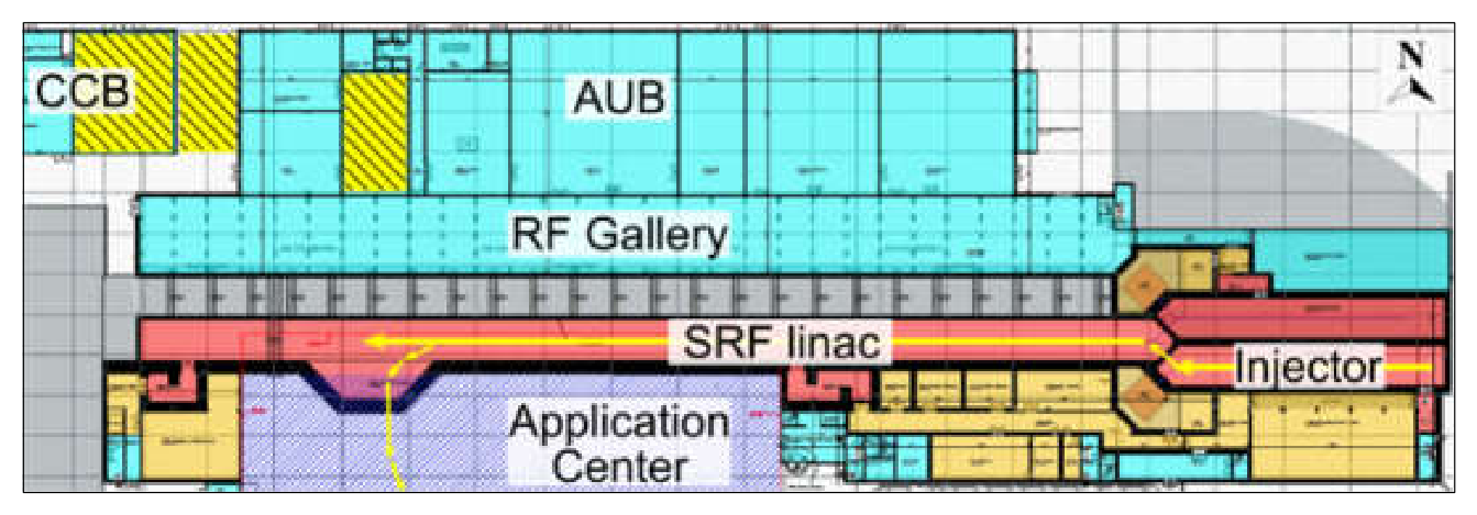
Figure 4.
Tunnel perspective.
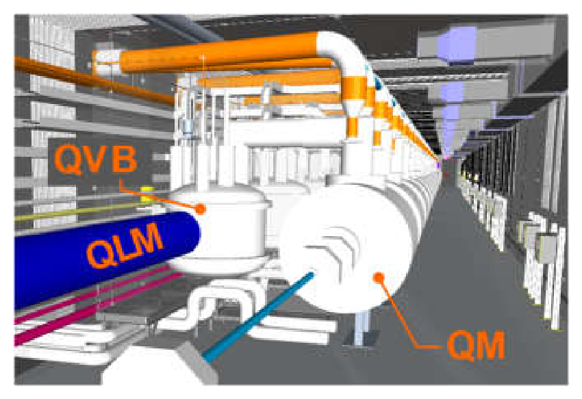
Figure 5.
Sequence of two QCELLs along the SRF linac, each comprising a cryomodule (QM) and dedicated valve box (QVB).
Figure 5.
Sequence of two QCELLs along the SRF linac, each comprising a cryomodule (QM) and dedicated valve box (QVB).
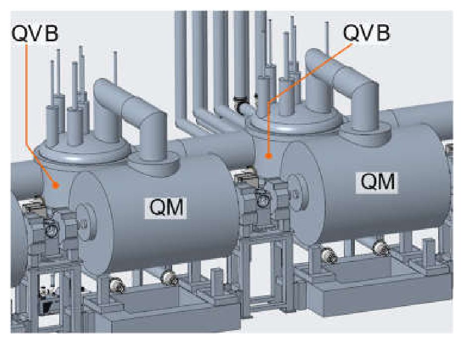
Figure 6.
The MINERVA Cryomodule [10]. A) Cavity in its Helium tank (CAV); B) Power coupler (CPLR); C) Cavity tuning system (TUN); D) Magnetic shield (MGS); Cryostat (QMST): E1) Vacuum Vessel; E2) Thermal Shield (TS); E3) Helium Buffer Tank; E4) Jumper interface (“Chimney”).
Figure 6.
The MINERVA Cryomodule [10]. A) Cavity in its Helium tank (CAV); B) Power coupler (CPLR); C) Cavity tuning system (TUN); D) Magnetic shield (MGS); Cryostat (QMST): E1) Vacuum Vessel; E2) Thermal Shield (TS); E3) Helium Buffer Tank; E4) Jumper interface (“Chimney”).
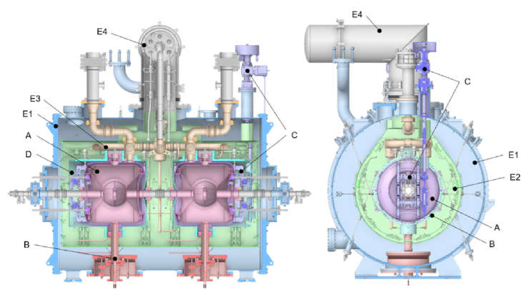
Figure 7.
Simplified cooling circuits of one QCELL as seen by the cryogenic distribution system.
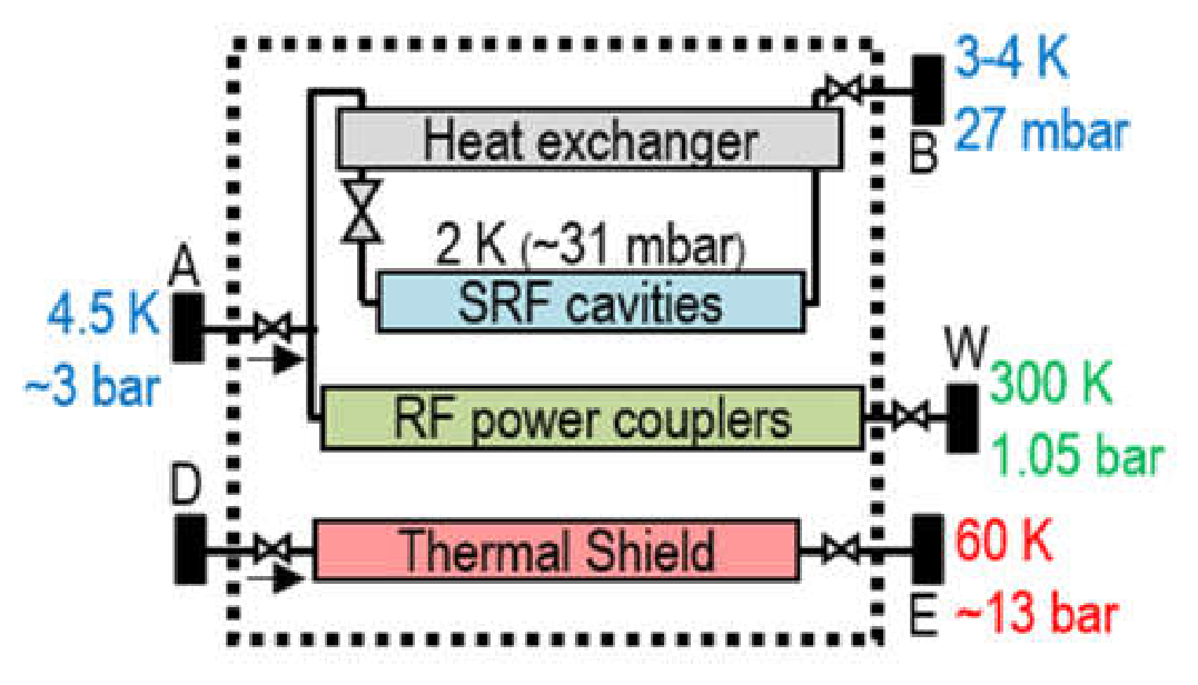
Figure 8.
Detailed process flow diagram (PFD) of a QCELL, showing the main, secondary, and tertiary circuit branches.
Figure 8.
Detailed process flow diagram (PFD) of a QCELL, showing the main, secondary, and tertiary circuit branches.
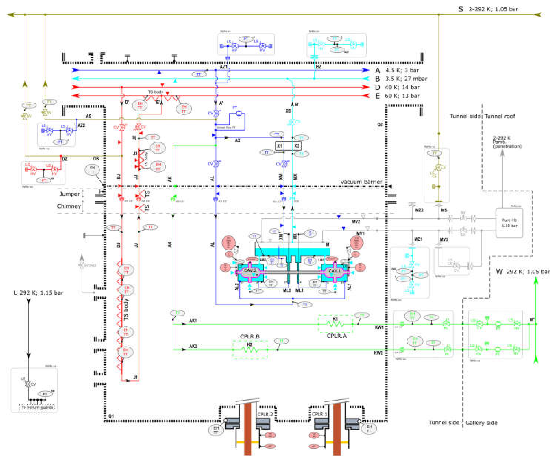
Figure 9.
Gradient Profile. Nominal accelerating gradient (Eacc) of each SRF cavity as a function of its position along the linac.
Figure 9.
Gradient Profile. Nominal accelerating gradient (Eacc) of each SRF cavity as a function of its position along the linac.
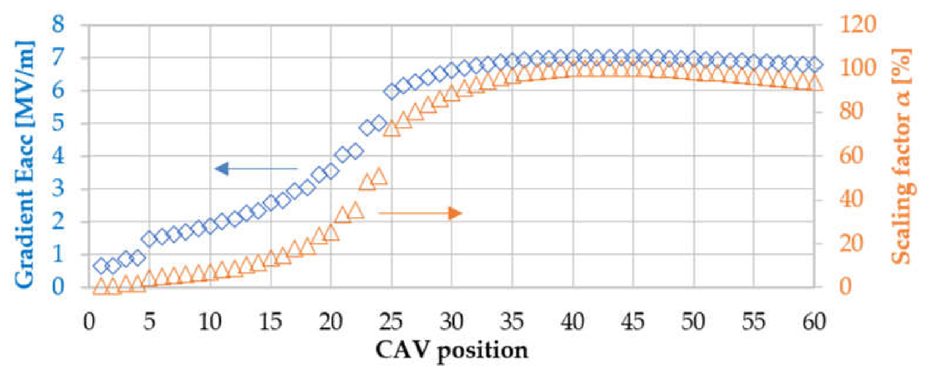
Figure 10.
Cryogenic process flow diagram (PFD) of the QPS [6]; preliminary version prior to public procurement.
Figure 10.
Cryogenic process flow diagram (PFD) of the QPS [6]; preliminary version prior to public procurement.
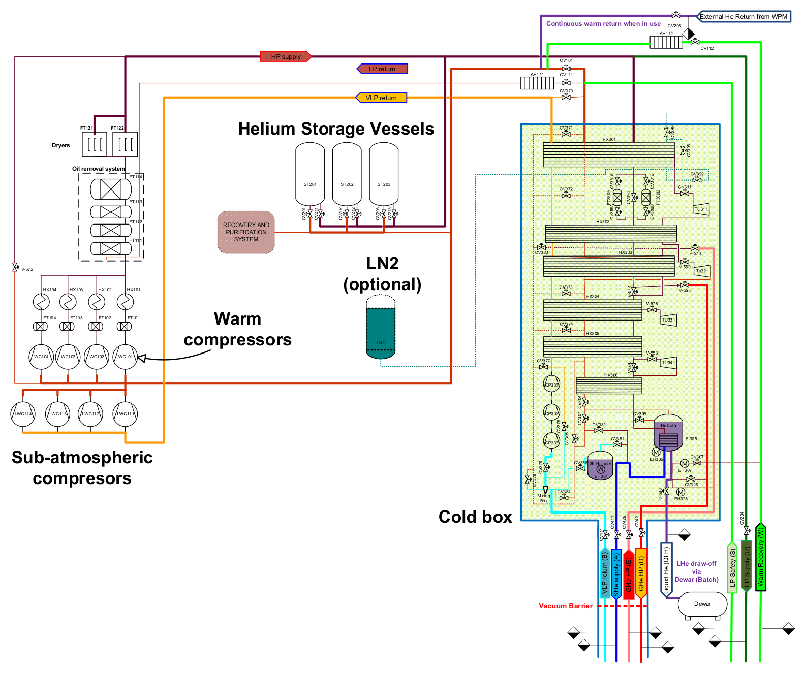
Figure 11.
The QPS operational-scenario sequence and its transitions.
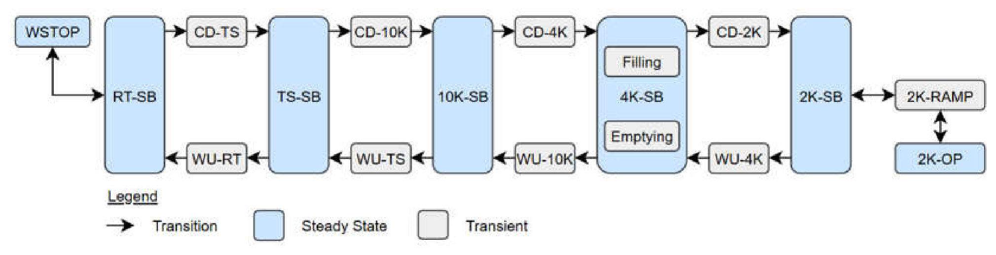
Figure 12.
Series components for the MINERVA cryomodules: (a) Single Spoke Cavity; (b) Magnetic Shield.
Figure 12.
Series components for the MINERVA cryomodules: (a) Single Spoke Cavity; (b) Magnetic Shield.

| Parameter | Symbol | Value |
|---|---|---|
| Beam energy range of the low beta section (β=0.351) | Ebeam | 16.6 MeV to 100 MeV |
| Quantity of SRF cavities | - | 60 (2 per cryomodule) |
| Cavity type (material) | - | Single spoke (bulk niobium) |
| Duty factor | - | CW ᵃ |
| Nominal resonant frequency (at Tcav) | f0 | 352.20 MHz |
| Operating temperature in linac | Tcav | 2 K |
| Accelerating RF field (max. nominal | max. peak) | Eacc | 7 MV/m | 9.1 MV/m |
| Cavity unloaded quality factor (at Tcav) | Q0 | > 5.2e9 up to 9.1 MV/m |
| Dissipated power in cavity walls (at Tcav) | Pcav | 4.25 W at Eacc = 7 MV/m |
| Allowable He bath pressure fluctuations | dP | ± 2 mbar |
ᵃ CW or pulsed with 4 ms cycles.
Table 2.
Required cooling capacity (static | dynamic | total) for a single QCELL, and for the entire SRF linac. Values are without contingency margins.
Table 2.
Required cooling capacity (static | dynamic | total) for a single QCELL, and for the entire SRF linac. Values are without contingency margins.
| Equipment | CAV Circuit [W] ᵉ | TS Circuit [W] | CPLR Circuit [g/s] |
|---|---|---|---|
| Single QCELL | 11.1 | 8.5 ᵃ | 19.6 | 186.3 | - | 186.3 | 0.040 | 0.012 | 0.052 |
| - QM only | 9.9 | 8.5 ᵃ | 18.4 | 100.8 | - | 100.8 | 0.040 | 0.012 | 0.052 |
| SRF linac | |||
| - 2K Standby ᶜ | 257.1 | - | 257.1 | 4851.0 | - | 4851.0 | 0.96 | - | 0.96 |
| - 2K Operation ᵈ | 337.4 | 165.8 ᵇ | 503.2 | 5900.8 | - | 5900.8 | 1.20 | 0.36 | 1.56 |
ᵃ Assumes 7 MV/m on both cavities (4.25 W RF losses each). ᵇ Function of the Gradient Profile (Figure 9). ᶜ For 2K-SB, LINAC_24, no RF. ᵈ For 2K-OP, LINAC_30, nominal gradient profile.ᵉ Excludes 1.4 W per QVB of static non-isothermal heat load (~2-3 K) towards Header B.
Table 3.
Main QDB header conditions at the QRB interface (nominal 2 K linac operation).
| Header | Circuit | Function | T [K] | P [bar] | ΔP [mbar] ᵃ |
|---|---|---|---|---|---|
| A | CAV | Supercritical He supply | 4.5 | 3 | 100 |
| B | CAV | 2 K saturated vapour return | 3.5 | 0.026 | 1 |
| D | TS | Thermal shield supply | 40 | 14 | 200 |
| E | TS | Thermal shield return | 60 | 13 | 200 |
ᵃ Allowable pressure drop across the QDB.
Table 4.
Specified refrigeration capacity of the cryoplant.
|
Condition |
Scenario |
QCAV [W] |
QTS [W] |
mCPLR [g/s] |
QB [W] |
Eq. Power ᵃ [Weq] |
|---|---|---|---|---|---|---|
| QPLANT Design Point | 2K-OP | 770 | 8200 | 2.3 | 81 | ~3.3 |
| QPLANT Standby Point | 2K-SB | 250 | 4800 | 0 | 49 | ~1.2 |
ᵃ Equivalent cooling power at 4.5 K expressed in “Watt equivalent” (Weq).
Table 5.
Helium inventory design basis (LINAC_30).
| Component | Basis | Mass (kg) |
|---|---|---|
| Cryomodules (QM) | 30 × ~12 kg each | 360 |
| Cryogenic Distribution Backbone (QDB) | QVBs + QVE + QLM | 45 |
| Warm Piping System (WPS) | — | 30 |
| Cryoplant & Storage (QPS) | Defined by Contractor | TBD ᵃ |
| External Dewar Users | — | 50 |
| Contingency margin | ≥30% of sub total | ~145 |
ᵃ To be defined — left to the Contractor’s process design; the WSH will be sized to include this contribution (incl. margin).
Table 6.
WPS line interface conditions at the QPS.
| Line | Temperature | Pressure | DN | Nominal flow [g/s] |
|---|---|---|---|---|
| W | amb. ±5 K | 1.1 bar ±10 mbar | DN40 | <3 |
| U | amb. ±5 K | ~1.5 bar (max 1.6 bar) | DN25 | ≤20 (conditioning) |
| S | amb. ±15 K | 1.1 bar ±5 mbar (min 1.05) | DN150 | ≤0.1 (residual); 100 (nominal); 150 (peak) |
amb. = ambient temperature (~293 K).
Disclaimer/Publisher’s Note: The statements, opinions and data contained in all publications are solely those of the individual author(s) and contributor(s) and not of MDPI and/or the editor(s). MDPI and/or the editor(s) disclaim responsibility for any injury to people or property resulting from any ideas, methods, instructions or products referred to in the content. |
© 2026 by the authors. Licensee MDPI, Basel, Switzerland. This article is an open access article distributed under the terms and conditions of the Creative Commons Attribution (CC BY) license.
Copyright: This open access article is published under a Creative Commons CC BY 4.0 license, which permit the free download, distribution, and reuse, provided that the author and preprint are cited in any reuse.