

Submitted:
09 October 2026
Posted:
12 October 2026
You are already at the latest version
Abstract
Affine frequency division multiplexing (AFDM) achieves full diversity in doubly selective channels. By exploiting its clear interference structure, decision feedback equalization (DFE) offers a robust, non-iterative receiver, yet suffers from severe error propagation. A permutation-driven DFE (P-DFE) framework is proposed to optimize both single-trajectory reliability and parallel structural diversity. For the single-branch P-DFE, permutation acts as an interference-shaping mechanism. Guided by derived statistical bounds, a low-complexity energy graph (EG) algorithm is developed to leverage the sparse AFDM channel for approximating optimal reliability sorting, reshaping the signal-to-interference-plus-noise ratio (SINR) profile to suppress initial errors. To decouple error propagation in high order constellations, permutation is elevated to a branch-generation tool for a parallel scheme. Specifically, a combination of cyclic shifts and time reversal is applied to the base order, generating a quality-preserving branch family. An optimal permutation-driven quad-branch DFE (P-QDFE) is configured by maximizing the harmonic mean of Kendall-Tau (KT) distances, minimizing inter-branch correlation. Simulations show P-QDFE effectively suppresses error floors in high-order modulations. At practical pre-decoding thresholds, this non-iterative scheme outperforms highly-iterated orthogonal approximate message passing (OAMP) under low-density parity-check (LDPC) coding, while integrating incomplete Cholesky factorization (ICHOL) ensures linear minimum mean square error (LMMSE)-level complexity.
Keywords:
affine frequency division multiplexing (AFDM)
; decision-feedback equalization (DFE)
; detection ordering
; doubly selective channels
; parallel multi-branch scheme
1. Introduction
Affine frequency division multiplexing (AFDM) provides an effective chirp-based multicarrier solution for next-generation wireless communications resilient to doubly dispersive fading [1]. By matching chirp sweep rates to the delay-Doppler profile of the channel through the discrete affine Fourier transform (DAFT), AFDM maps dense time-varying multipath into a quasi-sparse representation, thereby mitigating the inter-carrier interference (ICI) that destroys the subcarrier orthogonality of conventional orthogonal frequency division multiplexing (OFDM) [2]. This resilience to doubly selective dispersion is critical for high-speed railway and vehicular links, unmanned aerial vehicle (UAV)/air-to-ground and non-terrestrial connections, and millimeter-wave/sub-terahertz (sub-THz) integrated sensing and communications (ISAC) deployments [3,4,5]. Within these scenarios, recent studies position AFDM as a compact alternative to orthogonal time frequency space (OTFS) [6,7]. Furthermore, AFDM achieves full diversity gain with fast Fourier transform (FFT)-compatible complexity [8], resists hardware impairments in multiple-input multiple-output (MIMO) systems [9], and supports higher spectral efficiency through generalized spatial modulation (GSM) [10,11] or relaxed orthogonality constraints [12]. These transmission benefits position AFDM as a promising candidate waveform for future networks, but they also make reliable low-complexity detection over doubly selective channels a central receiver-design challenge.
Although recent channel-estimation advances [13] can provide accurate channel state information (CSI), reliable high-spectral-efficiency AFDM detection remains challenging because rich multipath and fractional delay and Doppler shifts induce severe inter-symbol interference despite DAFT-domain sparsity. Linear equalizers, such as zero-forcing (ZF) and linear minimum mean-square error (LMMSE) [14,15], therefore often remain sub-optimal, trading noise enhancement against residual interference under deep fading. Iterative detectors have therefore been investigated, but with distinct limitations. Iterative parallel interference cancellation (I-PIC) schemes [16] feed back block-wise tentative decisions to iteratively subtract interference, but suffer severe block-wise error propagation across iterations, where localized decision errors contaminate the entire block in subsequent feedback steps. Probabilistic message-passing paradigms offer statistical error control, yet low-complexity approximations such as the message passing algorithm (MPA) [17] lack robustness under high-order constellations and require stringent damping control. Conversely, exact matrix-solving counterparts such as orthogonal approximate message passing (OAMP) [18] achieve robust stability but incur high latency from numerous internal iterations, precluding low-latency deployment.
To circumvent the computational burden of iterative schemes, conventional DFE exploits structured channel interference for non-iterative reception [19,20], and the DAFT-domain symbol separation of AFDM naturally aligns with its successive interference cancellation (SIC) mechanism. However, DFE faces two practical bottlenecks. First, under doubly selective channels and high-order modulations, causal cancellation propagates early decision errors to subsequent stages. Second, single-branch DFE exhibits uneven symbol-wise reliability, weakening its synergy with channel coding schemes such as low-density parity-check (LDPC) codes [21]. Bidirectional DFE (BDFE) using time reversal [22,23,24] and bidirectional arbitrated decision-feedback equalization (BAD) [25] introduce branch diversity to mitigate error propagation, but they do not structurally decouple errors or optimize trajectories.
To overcome these bottlenecks, we introduce a permutation-driven DFE (P-DFE) methodology. Traditional single-carrier DFE (SC-DFE) [20] is restricted by chronological causality. Block-based waveforms such as AFDM and OTFS [26] remove this temporal constraint, yet existing block DFE and multi-branch BDFE receivers [22,24,27] underuse this freedom by confining detection to predefined natural or time-reversed sequences. Inspired by MIMO detection [28,29], we formulate sequence permutation as an explicit optimization variable. The resulting framework optimizes single-branch reliability and supports multi-branch structural diversity.
Permutation thus serves a dual role. First, it shapes interference by reshaping the signal-to-interference-plus-noise ratio (SINR) profile to suppress initial errors. Second, it uses the resulting single-branch reliability to generate parallel structural diversity. Using the Kendall–Tau (KT) distance [30] to quantify structural dissimilarity, we formulate a criterion for diverse yet quality-preserving decision trajectories. This reduces shared error-propagation paths, improves demodulated soft information, and integrates with modern channel coding.
The proposed framework differs from prior art in its use of detection order. Linear ZF/LMMSE equalizers lack decision feedback and are limited by residual interference or noise enhancement; conventional DFE, BDFE, and BAD-type receivers exploit feedback but remain tied to natural, reversed, or predefined trajectories; and iterative MPA/OAMP-type receivers improve reliability through repeated inference or matrix solving, with higher latency and cost. In contrast, P-DFE optimizes the detection permutation to shape single-branch reliability, while the proposed permutation-driven quad-branch DFE (P-QDFE) uses structurally diverse permutations to suppress correlated error propagation without iterative detection. The main contributions are summarized as follows.
- 1)
- We establish the P-DFE framework by formulating an exact mapping between the physical symbol domain and the sequential decision domain. Using this mapping, we reconstruct the interference model and derive recursions for the feedforward disturbance and propagated feedback error. This decomposition identifies the feedforward disturbance variance as the primary bottleneck, motivating permutation-based optimization.
- 2)
- Formulating permutation as a mechanism to shape the feedforward disturbance variance profile, we apply majorization theory under a genie-aided assumption to establish Sorted QR Decomposition (SQRD) [29] and Column-Pivoted QR (CPQR) [31] as statistical performance references for the proposed P-DFE. Guided by these references, we develop the Energy Graph (EG) ordering algorithm. By exploiting the sparse AFDM interference topology, EG approximates the SQRD performance while bypassing the complexity of repeated matrix factorization.
- 3)
- We extend permutation to parallel branch generation and propose permutation-driven multi-branch DFE (P-MBDFE). P-QDFE uses a quality-preserving shift/reversal family and a conservative KT harmonic-mean criterion. Starting from the physical symbol-wise error correlation, matched-ancestor and block-average relaxations yield the KT-based correlation model, calibrated by a linear scaling factor, for soft-output fusion; with LDPC coding, P-QDFE matches the evaluated iterated OAMP receiver at the reported pre-decoding bit error rate (BER) thresholds, while support-truncated incomplete Cholesky factorization (ICHOL) gives LMMSE-level critical-path complexity.
The paper is organized as follows. Section II introduces the AFDM transceiver and structured channel model. Section III develops P-DFE via permutation-based interference reconstruction, SINR, and error decomposition. Section IV establishes the genie-aided references and EG ordering algorithm. Section V introduces the non-iterative parallel P-MBDFE scheme, focusing on quality-preserving branch generation and KT optimization. Section VI presents simulation results, and Section VII concludes the paper.
Notations: Scalars, vectors, and matrices are denoted by lowercase, bold lowercase, and bold uppercase letters, respectively. For matrix entries, subscripts denote row and column. The operators , , and denote transpose, Hermitian transpose, and complex conjugate. is the identity matrix, and is the normalized discrete Fourier transform (DFT) matrix. forms a diagonal matrix. represents a complex Gaussian distribution with mean and variance . We use for the Gaussian Q-function, while denotes hard slicing to the nearest constellation point. Here denotes modulo-N reduction, the ceiling operation, the n-th largest component of a vector , and the binary indicator function. denotes the signal constellation.
2. AFDM System and Channel Model
AFDM employs the DAFT to map data symbols onto orthogonal chirps, transforming a dense doubly selective channel into a quasi-sparse effective channel. For zero-mean equiprobable symbols with , the inverse DAFT gives . The forward DAFT matrix is , where and . Both chirp matrices are unitary for real c; controls delay-Doppler separation and the secondary chirp phase. Frequently used quantities are summarized in Table 1; local indices and auxiliary variables are defined at their first occurrence.
A chirp-periodic prefix (CPP) of length enables a circular block model, with the maximum path delay in samples. To accommodate both integer- and fractional-delay paths, define the circulant delay operator
which reduces to the usual cyclic-shift power , with , when ℓ is integer. The signal propagates through a linear time-varying (LTV) channel modeled as
where L is the path count, and , , and are the complex gain, normalized delay in sampling intervals, and normalized Doppler shift of the i-th path, respectively. Here, and may both be fractional, and . After CPP removal, , with independent of . Unless otherwise specified, expectations below are conditioned on the realized . Applying the forward DAFT yields
where remains white Gaussian noise and is the effective DAFT-domain channel. For the integer-delay specialization, substituting the DAFT definition and (2) into (3) gives the compact -th entry
where , , , and
The Dirichlet kernel is interpreted by continuous extension at removable singularities. For fractional , (3) remains exact through (1), whereas (4)–(5) is the integer-delay specialization and fractional paths additionally exhibit delay-domain leakage. To separate the dominant integer-grid bins, is tuned as [1]
where and . Thus, is structurally sparse on the integer grid. When both delay and Doppler lie on that grid, each path occupies one dominant diagonal. Fractional Doppler and delay cause leakage; in that case (6) separates the dominant bins rather than eliminating leakage, whose energy nevertheless remains concentrated around those diagonals. This quasi-sparsity underpins the proposed equalizer.
3. Permutation-Driven Interference Reconstruction and P-DFE Scheme
Exploiting the block-wise reception of AFDM, P-DFE permutes the symbols within each received block before successive detection, thereby replacing the fixed symbol-detection order of conventional DFE with a configurable one. This ordering affects both its feedforward disturbance and its exposure to propagated decision errors. This section establishes the physical-to-stage mapping and derives the order-dependent reliability model used for permutation design. Figure 1 organizes the receiver into the four processing steps followed below.
3.1. P-DFE Model and Interference Reconstruction
Once permutation is introduced, the physical index of a symbol no longer coincides with its detection stage. We therefore distinguish the physical symbol domain from the detection-stage domain as
where indexes the transmitted information symbols and indexes their processing stages after permutation. The designed permutation matrix then defines a complete mapping between these two domains.
Let denote the stage-order vector, where is the physical symbol assigned to triangular stage k. Since backward substitution proceeds from N to 1, the chronological decision trajectory is . The inverse rank map and associated permutation matrix are defined by
where . The receiver flow is then expressed in the four steps of Figure 1.
1) Permutation (, ): The permutation block maps the received model to the stage domain as
where , , , and . Let denote the noise-to-symbol-energy ratio. The corresponding noise-regularized Gram matrices are
This operation does not change the physical channel; it changes the triangular couplings and pivot sequence seen by the detector.
2) Forward Filtering (): The feedforward (FF) equalizer in Figure 1 computes the Cholesky factorization of the Hermitian positive-definite matrix with its diagonal scaling separated:
where is unit lower triangular and is positive diagonal; equivalently, the conventional Cholesky factor is . These factors are computed recursively as
where . The FF equalizer output is
3) Backward Substitution (): The feedback (FB) equalizer in Figure 1 performs backward substitution for . Equations (11) and (14) give and . Its scalar input from the FF equalizer is
For previously detected stages , let and . Substitution into (15) gives the pre-normalized soft output
Under correct prior decisions, these moments give , where . The unbiased soft output is therefore
Thus the slicer operates on an unbiased output whose error is decomposed into an orthogonal FF disturbance and a propagated FB error.
4) Remapping (): Collecting the scalar outputs gives , and the inverse permutation returns them to the physical symbol domain. Hence , and performance is governed by the stage-wise SINR profile.
3.2. Order-Dependent Reliability Model
3.2.1. FF Disturbance Variance
The FF disturbance is the stochastic trigger for decision errors. Using the two moments above in (17), its variance is
Equation (19) shows that this variance is conditioned on the preceding factorization stages rather than being an intrinsic property of physical symbol . Different permutations therefore produce different residual projections. Since is permutation independent, maximizing remains equivalent to minimizing , making the diagonal pivot a direct surrogate for FF disturbance ordering.
3.2.2. FB Error Propagation
The FB error variance is governed jointly by the triangular coupling and the squared hard-decision error. To distinguish the latter from symbol error probability, define
In the high-reliability nearest-neighbor regime, . Under the scalar equivalent-Gaussian propagation model and neglecting cross-correlations among hard-decision errors, (17) gives
Substituting (12) and into (22) yields
Equation (23) shows that permutation jointly reshapes the residual triangular coupling, the effective denominator , and the reliability of later decisions. The FB recursion starts from , and may be stored in a look-up table.
3.2.3. Stage-Wise SINR
Under the same scalar auxiliary model, and in (17) are treated as zero mean, mutually uncorrelated, and uncorrelated with . Using the FF disturbance and FB error variances in (18) and (22), the effective stage-wise SINR is modeled as
Direct optimization is difficult because recursively depends on later decisions. We therefore use the tractable FF disturbance profile as a surrogate: reducing its vulnerable stages lowers the corresponding decision-error moments, while the net FB effect remains ordering dependent through (23).
4. Shaping the FF Disturbance Profile via Permutation Design
Building on the reconstructed interference model, this section utilizes permutation to explicitly shape the FF disturbance variance profile. By analyzing the sequential Cholesky factors under a genie-aided assumption, we apply majorization theory to establish SQRD and CPQR as statistical performance references. Consequently, we exploit the sparse AFDM interference topology to develop the low-complexity EG ordering, which approximates the SQRD reference without repeated full factorization.
4.1. Genie-Aided Analysis: SQRD and CPQR Bounds
Under genie-aided (GA) FB decisions [32], and (24) becomes . The determinant invariant therefore applies to rather than to the physical SINR itself. Its geometric mean is
Hence , where the ordering-dependent fluctuation satisfies
where denotes the profile generated by permutation .
Let denote the uncoded additive white Gaussian noise (AWGN) bit-error function of the adopted constellation and define . A second-order Taylor expansion around motivates the proxy
which approximates ; the first-order term vanishes because . Let and . Because varies across channel realizations, the moments in (28) and (31) are conditioned on a fixed , with this conditioning suppressed for notational consistency with the original formulation. The expectation becomes
Here, captures the mean-profile distortion and captures its channel-to-channel fluctuation.
Definition 1
(Majorization and Schur-Convexity [33]). For satisfying , majorizes (denoted by ) if for all , where . A function is Schur-convex if implies .
To derive the statistical performance references of P-DFE, SQRD [29] and CPQR [31] construct iteratively. At iteration k, let contain the physical symbols selected in the first factorization stages. In the notation of (12), the candidate pivot of a remaining symbol p is
where and denote the partial Cholesky quantities associated with the current selected set; equivalently, (29) is the Schur complement associated with . The next index is chosen over as
where ties are resolved by the smallest physical index. Since the FB recursion proceeds from stage N to stage 1, SQRD reserves stronger pivots for the earliest decisions, whereas CPQR applies the opposite allocation.
To investigate the statistical properties of SQRD and CPQR, Figure 2 compares the cumulative partial sums and profile variations. The nonintersecting expected-gap curves motivate the following statistical majorization hypothesis:
The annotations in Figure 2 are the corresponding un profile statistics, with . They provide descriptive motivation for (31), rather than a realization-wise proof, because sorting and expectation do not commute. The same trend motivates .
Proposition 1
(Statistical Proxy Bounds). Suppose (31) and the stated variance ordering hold, with for almost every . Averaging the resulting inequalities over gives
Proof.
See Appendix A. □
Thus SQRD and CPQR serve as the statistical performance references of P-DFE under the stated proxy model, rather than universal channel-by-channel BER bounds.
4.2. Fast Graph-Based Ordering Approximation
The complexity of standard SQRD is on the order of , which scales poorly with large block sizes. To mitigate this, we propose the EG ordering algorithm shown in Figure 3. EG replaces dense QR pivoting with reverse elimination on a pruned energy graph. As shown by the three steps in Figure 3, the procedure consists of energy-graph and heap initialization, node selection, and neighbor-key update.
4.2.1. Energy-Graph and Heap Initialization
Let denote the unregularized Gram matrix over , with for each active symbol. For , define the normalized coupling weight . The pruned energy graph is
where iff , , and ; the edge means that q is retained as a dominant interference source for p. Thus retains nonzero couplings rather than all pairs, while fractional leakage requires a positive threshold or explicit support truncation for sparsity. The retained energy and average directed degree are
where is used only when its denominator is nonzero. Once is fixed, we write and define and . For a remaining symbol set , the current residual interference power and heap key are
The heap is initialized with and keys .
4.2.2. Node Selection
At iteration t, the residual graph is the induced graph , where . EG extracts the maximum-key symbol from the heap and writes it into the reverse detection order:
then removes it by setting . Ties are resolved by the smallest physical index.
4.2.3. Neighbor Update
After is removed, only its remaining out-neighbors lose one residual interferer. For ,
and the updated key is . The procedure then returns to Step 2) Node Selection and repeats until all symbols are removed. The complete EG ordering flow is summarized in Algorithm 1.
| Algorithm 1 Energy-Graph (EG) Ordering Algorithm |
|
Given and the retained edge lists, initialization requires operations, heap extraction requires , and neighbor updates require . Each node is extracted exactly once and each directed edge triggers at most one key update. Therefore,
Figure 4 shows that, in the evaluated setting, EG tracks the SQRD reference across FF disturbance, FB error, and reconstructed-SINR profiles while avoiding repeated global pivot searches.
5. Decoupling Error Propagation via Parallel P-MBDFE Scheme
Although ordering enhances the performance of a single-branch equalizer, the P-DFE remains highly vulnerable to error propagation under severe channel conditions or high-order modulations. To address this limitation, we extend reordering beyond the optimization of a single-branch perspective; instead, we leverage permutation to construct a family of multiple branches that simultaneously exhibit high performance and reduced shared feedback topology. Guided by the structural symmetry of AFDM channels and the KT distance metric, we propose the P-MBDFE architecture to achieve these design objectives.
5.1. P-MBDFE Roadmap
Figure 5 summarizes the proposed P-MBDFE receiver as a continuation of the single-branch ordering framework developed in Section 3 and Section 4.2. The EG module first provides a high-quality base order for a single P-DFE branch. Starting from this base order, the multi-branch construction module generates a set of candidate permutations by exploiting AFDM structural symmetries, while the offline KT-based selection path identifies the optimal branch set . Each selected element is a permutation applied to an otherwise identical P-DFE detector, rather than a new detector state.
This roadmap also clarifies the organization of the remainder of this section. Section 5.2 first derives the fusion objective and shows that P-MBDFE must simultaneously preserve branch-wise reliability and suppress residual inter-branch correlation. Section 5.3 addresses the first requirement by constructing a quality-preserving shift/reversal branch family, and Section 5.4 addresses the second requirement by selecting branches with large KT distance. The selected branches are then executed in parallel, fused by maximum-ratio combining (MRC), and converted into bit log-likelihood ratios (LLRs) for decoding.
5.2. Fusion Gain of P-MBDFE and Optimization Objective
To suppress feedback sensitivity, P-MBDFE introduces B branches with distinct permutation matrices . For branch b, let and ; in implementation, this branch mean-square error (MSE) is estimated by at using (18) and (22). Since the full cross-branch covariance is unavailable online, the branch MSEs form the inverse-variance weights
For two branches, define the physical symbol-wise error correlation
For equiprobable constellation labels, the matched Max-Log LLR under the standard Gaussian residual model is
where and denote the subsets of constellation points with the j-th bit equal to 0 and 1, respectively. A smaller actual variance in (41) makes the fused observation more informative and improves the resulting LLR quality. The actual , however, is unavailable online, so the matched variance in (42) cannot be evaluated directly; merely replacing it by an underestimated value would inflate and produce overconfident soft information.
Improving the fused observation and calibrating its LLRs are distinct but successive objectives addressed in three stages. First, Section 5.3 preserves a large through quality-preserving branch generation. Second, Section 5.4 links shared feedback ancestry to KT overlap and maximizes harmonic KT separation, enabling branch selection without unavailable symbol-wise correlations and yielding a provable envelope for the correlation penalty. Third, after branch selection, a single scale factor sets the correlation magnitude used in the fusion-variance estimate and LLR computation.
5.3. Quality-Preserving Branch Generation
We first preserve branch-wise reliability before optimizing cross-branch diversity. Equation (41) shows that this requires a large , with each reliable branch contributing through its inverse MSE. Permutation diversity alone does not ensure this: an arbitrary detection order can create weak stages and severe error propagation, yielding a large and therefore only a small contribution to . At , the fusion model approximates the branch MSE as . Combining this approximation with (24) gives , so branches with higher stage-wise SINR contribute more strongly to .
The EG base order therefore serves as the reliability reference for branch generation. To obtain distinct decision trajectories without sacrificing this reliability, we exploit the near-circulant structure of its ordered Gram matrix. Cyclic shifts and reversal approximately preserve the stage-wise SINR profile and hence the branch contributions to , yielding the candidate family
where is the cyclic-shift matrix and for one-based indices. Each element of is a complete branch permutation matrix. The following proposition formalizes its SINR quasi-invariance relative to the EG base order.
Proposition 2
(SINR Quasi-Invariance via Structure Preservation). Let the base-ordered regularized Gram matrix be , where is the dominant Hermitian circulant component and is the residual. For any , define and . Their Gram matrices satisfy and , with . If and is sufficiently small, the stage-wise GA SINR profiles satisfy
Proof.
See Appendix B. □
5.4. Diversity Selection via Kendall–Tau Distance
After preserving branch quality, the remaining design objective in (41) is to reduce . Because the exact symbol-wise correlations are unavailable during offline branch selection, we seek a permutation-only characterization of their order dependence.
To construct this characterization, we first express each branch error in the physical-symbol domain. Figure 7 illustrates the detected/undetected partition induced by each order through the rank function .
For a physical symbol under permutation , define the undetected set (symbols not yet detected when m is processed) and the detected set (symbols already detected and used for cancellation when m is processed) as
Based on (17), the soft-decision error at stage k equals plus weighted contributions from previously detected decision errors:
For a physical symbol , let . Remapping (46) with the detected set in (45b) gives
where denotes after remapping to physical symbol m, is the order-dependent transfer coefficient from to , and is the hard-decision error at physical symbol p. Expanding (47) for two branches and , while neglecting cross terms between the terms and the decision errors, gives
where is the cross-covariance between the two remapped terms, , , and . The last line retains contributions from decision errors associated with symbols detected under both orders and neglects cross-symbol decision-error moments. Normalizing its real part according to (40) gives
where and . For any unordered symbol pair , the two detection orders either preserve or reverse its relative order. In the former case, exactly one orientation of the pair appears in the detected-set intersections; in the latter, neither orientation appears and the pair contributes one inversion. This one-to-one correspondence motivates the Kendall–Tau distance.
Definition 2
(Kendall–Tau Distance). For two permutations π and , define
which counts their pairwise order inversions [30].
Because permutations have no rank ties, this correspondence gives . Dividing by the total number of symbol pairs gives
Using in the correlation penalty of (41), while retaining the branch-specific inverse-MSE weights, gives
Equation (51) uses in place of the unavailable pairwise correlations while preserving the inverse-MSE weights in (41).
To penalize highly similar branch pairs, we use the harmonic mean of their KT distances. Its relation to is established below.
Proposition 3
(Harmonic KT Branch Selection). For a B-branch set , let , , and . Define
with if any , and let . Then , with equality if and only if all pairwise distances are equal, and, for every symbol m,
Hence maximizing exactly minimizes the aggregate inverse-distance risk , balances the weakest branch pairs, and minimizes the stated reliability-independent envelope of .
Proof.
See Appendix C. □
Proposition 3 establishes as the robust criterion for reducing . The offline selected subset is therefore
Figure 8 supports the inverse relation between and the actual cross-branch correlation over the evaluated branch subsets. For the block-level approximation, we neglect the average of in (49) and replace by a common value for . Let . Equations (49) and (50) then give
Applying this block-level approximation to the correlation penalty gives
The variance supplied to the soft demodulator is therefore
Thus, selects branches with less similar detection orders, whereas sets the correlation magnitude used in the fusion variance and hence the LLR scale.
With the offline branch set in (53) and the calibrated fusion variance in (55), the complete P-MBDFE receiver operates in three phases: 1) Branch Generation: Constructing from the EG-ordered base permutation; 2) Parallel Detection: Executing P-DFE for each branch to obtain soft symbols and reliability metrics; and 3) Fusion: Combining the outputs via the MRC rule in (39), evaluating the fusion variance via (51) and (55), and computing final LLRs for decoding via (42).
As a concrete implementation example of this framework with , as derived in Appendix D, a KT-optimal P-QDFE configuration is
This specific instance, referred to as the P-QDFE scheme, comprises the base order, its semi-circle shift, and their time-reversed counterparts, as verified in Figure 8. The complete P-MBDFE procedure is summarized in Algorithm 2.
| Algorithm 2 Proposed P-MBDFE Receiver |
|
5.5. Computational Complexity
The P-MBDFE scheme comprises four stages: shared initialization, base ordering, parallel detection, and fusion. The initialization exploits the sparse effective channel to compute the Gram matrix and matched filter, bounded by . The EG base ordering relies primarily on priority queue updates and has the complexity in (38). The proposed receiver uses a configurable ICHOL factorization [34] for each branch. Setting retains the complete elimination graph and recovers the full factorization in (11), whereas drops weak fill entries. Let denote the root-mean-square (RMS) number of retained nonzeros per factor column. The B branches then require operations for factorization and FF/FB processing. Finally, MRC fusion and Max-Log LLR extraction require operations. Since and are predefined, the LLR variance calibration in (55) introduces no additional computational complexity.
Therefore, the total sequential complexity is . Moreover, the B-branch parallel execution confines the critical path to shared preprocessing, single-branch evaluation, and fusion. This bounds the parallel computational complexity order to , decoupling the execution latency from the number of branches.
6. Simulation Results
In this section, we evaluate the proposed equalizers under two channel models: multipath Rayleigh fading channels for stress testing, and the 3rd Generation Partnership Project (3GPP) tapped-delay-line C (TDL-C) profile [35] for dense high-mobility fractional delay-Doppler validation. For the Rayleigh fading channels, each path has equal average power , where L is the number of paths, and the maximum normalized delay shift is . Under integer Doppler, the path Doppler shifts are chosen uniformly from the integer set with . Under fractional Doppler, they follow the Jakes model with and . Unless otherwise stated, we set and . The two-branch permutation-driven BDFE (P-BDFE) utilizes the EG base order and its reversal, whereas the four-branch P-QDFE utilizes the optimal configuration in (56). Coded curves use the 3GPP New Radio (NR) LDPC base graph 2 (BG2) protograph [36], lifting size , and rate matching.
Perfect CSI is assumed except for the TDL-C robustness test, where the receiver reconstructs from perturbed path gains and delay-Doppler parameters [37,38]. For the imperfect-CSI sweep, define , , and the path-gain normalized mean-square error (NMSE) , reported as dB. Setting , generate with , , and . Here , , , and .
Figure 9 evaluates the single-branch DFE under various orderings against their genie-aided bounds under 4-path fractional delay-Doppler channels. SQRD and CPQR bound the ensemble performance. We observe that: first, the low-complexity EG tightly tracks SQRD, yielding SNR gains over natural ordering of dB for QPSK at a BER of and dB for 16QAM at a BER of by deferring high-interference symbols to later stages to shape the stage-wise SINR profile; second, the gap between the actual and genie-aided EG curves widens under higher-order modulations, reflecting their stronger sensitivity to error propagation and motivating the multi-branch design evaluated next.
Figure 9b extends the same setting to P-BDFE and P-QDFE across constellations and orderings. Branch-diversity gain grows with constellation order, with all gains evaluated relative to the Bi-Natural baseline at the maximum evaluated SNR of the respective modulation. Under QPSK, the large Euclidean distance limits error propagation, yielding nearly identical performance across different equalizers. Under 8-ary phase-shift keying (8PSK), at the Bi-Natural BER of at 18 dB, Bi-EG and Quad-EG improve by dB and dB, respectively. For 16QAM, at the Bi-Natural BER of at 20 dB, Bi-EG and Quad-EG provide dB and dB gains. For 32-ary amplitude and phase-shift keying (32APSK), at the Bi-Natural BER of at 22 dB, the gains rise to dB and dB. This confirms KT-guided diversity and near-SQRD EG ordering.
Figure 9c evaluates the EG pruning rule in (33) using the BER permutation gain , together with the retained coupling-energy ratio and average graph degree defined in (34). For QPSK, the unpruned single-branch stays in a narrow range from to as L increases from 4 to 16, showing that the ordering gain is stable under low-order modulation. For 16QAM, rises from at and stays around - for -16. This indicates that EG remains robust and becomes more beneficial in richer multipath channels. At , drops from 511 to - while still retains - of the coupling energy. The resulting remains positive, ranging from to for QPSK and from to for 16QAM. Therefore, is used in the remaining simulations as a practical trade-off between graph sparsity and BER gain.
Figure 10 compares the uncoded BER performance of the proposed equalizers against DFE baselines and iterative benchmarks under ideal sparse integer delay-Doppler channels. Under QPSK, P-DFE yields a dB gain over DFE at dB, where the baseline BER is . Meanwhile, due to the low modulation order, the multi-branch equalizers P-BDFE, P-QDFE, and BDFE exhibit similar performance, closely approaching the OAMP benchmark. Under 16QAM, the low-complexity MPA benchmark with iterations fails even in this ideal sparse channel, with damping factor stagnating near and still near at dB. In contrast, the proposed equalizers yield significant gains. P-DFE provides a dB gain over DFE at dB, where the baseline BER is . Similarly, P-BDFE and P-QDFE achieve dB and dB gains over BDFE at dB, where the baseline BDFE BER is , with P-QDFE reaching to closely approach the best evaluated OAMP configuration using and , which achieves . This confirms the efficacy of the proposed equalizers in ideal sparse channels.
Furthermore, Figure 11 investigates the equalizers with 16QAM under the dense fractional-delay and fractional-Doppler TDL-C channel and imperfect CSI settings summarized in Table 2. In Figure 11a, under perfect CSI, P-DFE achieves a BER of at dB. For multi-branch equalizers, P-BDFE yields a dB gain over OAMP using and at dB, where the baseline OAMP BER is . Similarly, P-QDFE achieves a dB gain over OAMP using and at dB, where the baseline OAMP BER is . In Figure 11b, the EG-ordered receivers retain their gain over the natural DFE/BDFE baselines up to a nominal path-gain NMSE of about dB, indicating that the EG ordering remains useful under moderate delay-Doppler mismatch for 16QAM. Across the full CSI-perturbation sweep, P-QDFE achieves the best BER, showing that the quad-branch architecture further improves robustness under non-ideal CSI.
Prior to coded BER evaluation, Table 3 and Table 4 validate the KT-based LLR variance calibration using the standard bit-wise normalized generalized mutual information (NGMI) computed from the LLRs in (42). As one practical selection criterion, Table 3 chooses by average NGMI, while Table 4 shows a NGMI gain at dB over the uncorrected variance; the resulting P-QDFE soft output also exceeds unbiased LMMSE at every evaluated point.
Figure 12 illustrates the uncoded and coded BER performance under 16QAM over a 5-path fractional Doppler channel, utilizing a code rate of , yielding a spectral efficiency of 2.50 bits/s/Hz, and the belief propagation (BP) decoder [39]. Under coded transmission, P-QDFE yields a dB gain over unbiased LMMSE at dB, where the baseline unbiased LMMSE BER is . Notably, while the OAMP configuration with , , and an OAMP-specific LLR scaling factor of , empirically optimized via parameter sweeping, achieves a lower uncoded BER, P-QDFE exhibits a steeper coded waterfall curve, yielding a dB gain over OAMP at dB, where the baseline OAMP BER is . Although this scaling may not represent OAMP’s performance limit under a joint design, the comparison demonstrates the coded robustness of P-QDFE.
Figure 13 illustrates the coded BER-complexity trade-off under ICHOL, where is the arithmetic-mean number of retained nonzeros per factor column; the asymptotic operation term uses the RMS degree defined above. At code rate and dB, increasing reduces the average filter complexity. Under integer Doppler, decreases from about to at , where P-QDFE and unbiased LMMSE yield BERs and ; at their BERs are and . Under fractional Doppler, spectral leakage raises the initial to , while the same threshold reduces it to , corresponding to a complexity reduction. P-QDFE and unbiased LMMSE then yield and , respectively. Furthermore, Table 5 and Figure 14 compare the critical path complexity for 16QAM (, ). Iterative algorithms scale rapidly: MPA scales linearly with constellation size ( operations at ), while OAMP requires dense matrix operations (). In contrast, parallel P-QDFE decouples computational depth from the branch count, requiring only operations, matching LMMSE () and achieving multi-branch diversity without iterative latency scaling.
7. Conclusion
In this paper, a permutation-driven decision feedback equalization framework was proposed for AFDM, which unifies single-branch reliability and multi-branch diversity. In the single-branch P-DFE, permutation served as an interference-shaping mechanism. Guided by derived statistical bounds, a low-complexity EG algorithm was developed to approximate the optimal reliability sorting. Moreover, to decouple error propagation in high order constellations, permutation was utilized to generate structural diversity for the parallel P-MBDFE, where the optimal four-branch P-QDFE was configured via KT distance maximization. Simulations confirmed that the proposed P-QDFE suppressed error floors in high-order modulations. By utilizing LDPC coding, the non-iterative P-QDFE can attain nearly identical BER performance compared to the iterative OAMP equalizer, preventing convergence stagnation at pre-decoding thresholds. Finally, by integrating ICHOL, this parallel scheme provides an efficient receiver with promising complexity vs. BER trade-offs.
Funding
This work was supported in part by the National Natural Science Foundation of China under Grant 62671214, and in part by the Major Key Project of Pengcheng Laboratory under Grant PCL2024A01.
Appendix A. Proof of Proposition 1
Condition on . The function is symmetric and Schur-convex, so (31) orders the mean-profile term in (28); the stated variance ordering orders its fluctuation term. Under the standard approximation with constellation-dependent , direct differentiation gives . When , (28) preserves both orderings. Averaging over proves (32).
Appendix B. Proof of Proposition 2
For any s, Hermitian-circulant structure gives and . Using therefore yields and . Unitary invariance and the triangle inequality give the matrix perturbation bounds stated above. Assume and that is sufficiently small. Let and denote the k-th diagonal pivots of and , respectively, for . The shift branch is compared with , whereas the reversal branch is compared with , whose real diagonal pivots equal those of . Each pivot is the Schur complement of the leading principal block. On a positive-definite neighborhood whose eigenvalues are bounded away from zero, inversion and successive Schur complements are locally Lipschitz; applying this property recursively gives
Complex conjugation leaves these real pivots unchanged, and maps this pivot perturbation to (44), proving Proposition 2.
Appendix C. Proof of Proposition 3
Let . Equation (52) gives , so maximizing is exactly equivalent to minimizing the aggregate inverse-distance risk. The harmonic–arithmetic mean inequality yields , with equality if and only if all are equal; the reciprocal terms also diverge as any approaches zero, establishing the weak-pair sensitivity.
Appendix D. Proof of the Optimal Configuration
Every branch has the form or . Common right multiplication by only relabels physical items, so pairwise KT distances can be evaluated for the shift/reversal actions. If , direct inversion counting gives and . With and distances scaled by , these converge to and . Thus the harmonic-mean problem is equivalent to minimizing over these limiting distances. Let , , , and . For and , differentiation shows that with a positive denominator, where is strictly decreasing in . Thus the minimum of over is attained at or . With and , the two endpoint candidates satisfy
where with . Hence for .
The three orientation splits are bounded as follows. In , the six same-orientation separations average at most . In , with denoting same-orientation circular separations and the distances to the opposite-orientation branch, and imply . In , same-orientation separations give cross terms at least . Hence,
The balanced lower value is attained for two half-cycle-separated same-orientation pairs, giving (56) up to common shift, reversal, and branch relabeling. Since , minimizes the limiting and asymptotically maximizes .
References
- Bemani, A.; Ksairi, N.; Kountouris, M. Affine frequency division multiplexing for next generation wireless communications. IEEE Trans. Wirel. Commun. 2023, 22, 8214–8229. [Google Scholar] [CrossRef]
- Yin, H.; Tang, Y.; Bemani, A.; Kountouris, M.; Zhou, Y.; Zhang, X.; Liu, Y.; Chen, G.; Yang, K.; Liu, F.; et al. Affine Frequency Division Multiplexing: Extending OFDM for Scenario-Flexibility and Resilience. IEEE Wirel. Commun. 2025, 32, 200–208. [Google Scholar] [CrossRef]
- Sui, Z.; Luo, Q.; Liu, Z.; Temiz, M.; Musavian, L.; Masouros, C.; Guan, Y.L.; Xiao, P.; Hanzo, L. Multi-functional chirp signalling for next-generation multi-carrier wireless networks: Communications, sensing and ISAC perspectives. arXiv 2025, arXiv:2508.06022. [Google Scholar]
- Li, Q.; Li, J.; Wen, M.; Dang, X.; Arslan, H.; Al-Dhahir, N. Affine Frequency Division Multiplexing for 6G Networks: Fundamentals, Opportunities, and Challenges. IEEE Netw. 2026, 40, 88–97. [Google Scholar] [CrossRef]
- Rou, H.S.; Ranasinghe, K.R.R.; Savaux, V.; de Abreu, G.T.F.; González, G.D.; Masouros, C. Affine Frequency Division Multiplexing (AFDM) for 6G: Properties, Features, and Challenges. IEEE Commun. Stand. Mag. 2026, 10, 216–225. [Google Scholar] [CrossRef]
- Rou, H.S.; de Abreu, G.T.F.; Choi, J.; González, D.G.; Kountouris, M.; Guan, Y.L.; Gonsa, O. From Orthogonal Time-Frequency Space to Affine Frequency-Division Multiplexing: A Comparative Study of Next-Generation Waveforms for Integrated Sensing and Communications in Doubly Dispersive Channels. IEEE Signal Process. Mag. 2024, 41, 71–86. [Google Scholar] [CrossRef]
- Bemani, A.; Ksairi, N.; Kountouris, M. Integrated Sensing and Communications With Affine Frequency Division Multiplexing. IEEE Wirel. Commun. Lett. 2024, 13, 1255–1259. [Google Scholar] [CrossRef]
- Savaux, V. Special cases of DFT-based modulation and demodulation for affine frequency division multiplexing. IEEE Trans. Commun. 2024, 72, 7627–7638. [Google Scholar] [CrossRef]
- Sui, Z.; Liu, Z.; Musavian, L.; Guan, Y.L.; Yang, L.L.; Hanzo, L. MIMO-AFDM Outperforms MIMO-OFDM in the Face of Hardware Impairments. arXiv 2026, arXiv:2601.00502. [Google Scholar]
- Sui, Z.; Liu, Z.; Musavian, L.; Yang, L.L.; Hanzo, L. Generalized spatial modulation aided affine frequency division multiplexing. IEEE Trans. Wirel. Commun. 2026, 25, 4658–4673. [Google Scholar] [CrossRef]
- Gao, P.; Zhu, J.; Zhang, K.; Mei, L.; Ma, S.; Wang, Y.; Li, X. Multi-domain generalized index modulation aided MIMO-AFDM for future high-mobility communications. IEEE Trans. Veh. Technol. 2025. [Google Scholar] [CrossRef]
- Yi, Q.; Liu, Z.; Musavian, L.; Sui, Z. Non-orthogonal affine frequency division multiplexing for spectrally efficient high-mobility communications. arXiv 2025, arXiv:2508.09782. [Google Scholar]
- Zheng, K.; Wen, M.; Mao, T.; Xiao, L.; Wang, Z. Channel Estimation for AFDM With Superimposed Pilots. IEEE Trans. Veh. Technol. 2025, 74, 3389–3394. [Google Scholar] [CrossRef]
- Tiwari, S.; Das, S.S.; Rangamgari, V. Low complexity LMMSE receiver for OTFS. IEEE Commun. Lett. 2019, 23, 2205–2209. [Google Scholar] [CrossRef]
- Surabhi, G.D.; Chockalingam, A. Low-complexity linear equalization for OTFS modulation. IEEE Commun. Lett. 2020, 24, 330–334. [Google Scholar] [CrossRef]
- Iqbal, N.; Zerguine, A.; Alouini, M.S. A Robust Frequency Domain Decision Feedback Equalization System for Uplink SC-FDMA Systems. IEEE Trans. Wirel. Commun. 2021, 20, 8110–8118. [Google Scholar] [CrossRef]
- Raviteja, P.; Phan, K.T.; Hong, Y.; Viterbo, E. Interference cancellation and iterative detection for orthogonal time frequency space modulation. IEEE Trans. Wirel. Commun. 2018, 17, 6501–6515. [Google Scholar] [CrossRef]
- Ma, J.; Ping, L. Orthogonal AMP. IEEE Access 2017, 5, 2020–2033. [Google Scholar] [CrossRef]
- Williamson, D.; Kennedy, R.A.; Pulford, G.W. Block decision feedback equalization. IEEE Trans. Commun. 1992, 40, 255–264. [Google Scholar] [CrossRef]
- Al-Dhahir, N.; Cioffi, J.M. MMSE decision-feedback equalizers: Finite-length results. IEEE Trans. Inf. Theory 1995, 41, 961–975. [Google Scholar] [CrossRef]
- Gallager, R.G. Low-density parity-check codes. IRE Trans. Inf. Theory 1962, 8, 21–28. [Google Scholar] [CrossRef]
- Yin, C.; Feng, W.; Li, J.; Bao, X.; Li, G. Soft-Input Soft-Output Block Decision Feedback Equalization for ISI Channels. IEEE Trans. Commun. 2021, 69, 6213–6224. [Google Scholar] [CrossRef]
- Tomasin, S. Efficient bidirectional DFE for doubly selective wireless channels. EURASIP J. Adv. Signal Process. 2006, 2006, 070572. [Google Scholar] [CrossRef]
- Ye, Z.; Yan, S.; Sui, Z.; Zhang, H.; Sun, S. Successive interference cancellation aided bidirectional soft decision feedback equalization for OTFS systems. IEEE Wirel. Commun. Lett. 2023, 12, 2028–2032. [Google Scholar] [CrossRef]
- Nelson, J.K.; Singer, A.C.; Madhow, U.; McGahey, C.S. BAD: Bidirectional arbitrated decision-feedback equalization. IEEE Trans. Signal Process. 2005, 53, 227–239. [Google Scholar] [CrossRef]
- Wei, Z.; Yuan, W.; Li, S.; Yuan, J.; Bharatula, G.; Hadani, R.; Hanzo, L. Orthogonal Time-Frequency Space Modulation: A Promising Next-Generation Waveform. IEEE Wirel. Commun. 2021, 28, 136–144. [Google Scholar] [CrossRef]
- Zhu, S.; Du, Z.; Mei, L. Bidirectional Block Decision Feedback Equalization for the Hybrid Carrier System. IEEE Commun. Lett. 2025, 29, 1704–1708. [Google Scholar] [CrossRef]
- Loyka, S.; Gagnon, F. Performance analysis of the V-BLAST algorithm: An analytical approach. IEEE Trans. Wirel. Commun. 2004, 3, 1326–1337. [Google Scholar] [CrossRef]
- Kim, T.H. Low-Complexity Sorted QR Decomposition for MIMO Systems Based on Pairwise Column Symmetrization. IEEE Trans. Wirel. Commun. 2014, 13, 1388–1396. [Google Scholar] [CrossRef]
- Kendall, M.G. A new measure of rank correlation. Biometrika 1938, 30, 81–93. [Google Scholar] [CrossRef]
- Kaloorazi, M.F.; Chen, J. Projection-Based QLP Algorithm for Efficiently Computing Low-Rank Approximation of Matrices. IEEE Trans. Signal Process. 2021, 69, 2218–2232. [Google Scholar] [CrossRef]
- Altekar, S.; Vityaev, A.; Wolf, J. Decision-feedback equalization via separating hyperplanes. IEEE Trans. Commun. 2001, 49, 480–486. [Google Scholar] [CrossRef]
- Marshall, A.W.; Olkin, I. Inequalities: Theory of Majorization and Its Applications; Academic Press, 1979. [Google Scholar]
- Manteuffel, T.A. An incomplete factorization technique for positive definite linear systems. Math. Comput. 1980, 34, 473–497. [Google Scholar] [CrossRef]
- 3GPP. Study on channel model for frequencies from 0.5 to 100 GHz. Technical Report TR 38.901, 3rd Generation Partnership Project (3GPP);Rel. 17. 2022.
- 3GPP. NR; Multiplexing and channel coding. Technical Report TS 38.212, 3rd Generation Partnership Project (3GPP); NR; Multiplexing and channel coding. Rel. 17. 2022.
- Gaudio, L.; Kobayashi, M.; Bissinger, B.; Caire, G. On the Effectiveness of OTFS for Joint Radar Parameter Estimation and Communication. IEEE Trans. Wirel. Commun. 2020, 19, 5951–5965. [Google Scholar] [CrossRef]
- Zhao, T.; Huang, T. Cramer-Rao Lower Bounds for the Joint Delay-Doppler Estimation of an Extended Target. IEEE Trans. Signal Process. 2016, 64, 1562–1573. [Google Scholar] [CrossRef]
- MacKay, D.J.C. Good error-correcting codes based on very sparse matrices. IEEE Trans. Inf. Theory 1999, 45, 399–431. [Google Scholar] [CrossRef]
Figure 1.
Block diagram of the permutation-driven DFE (P-DFE) receiver and its four processing steps.
Figure 1.
Block diagram of the permutation-driven DFE (P-DFE) receiver and its four processing steps.
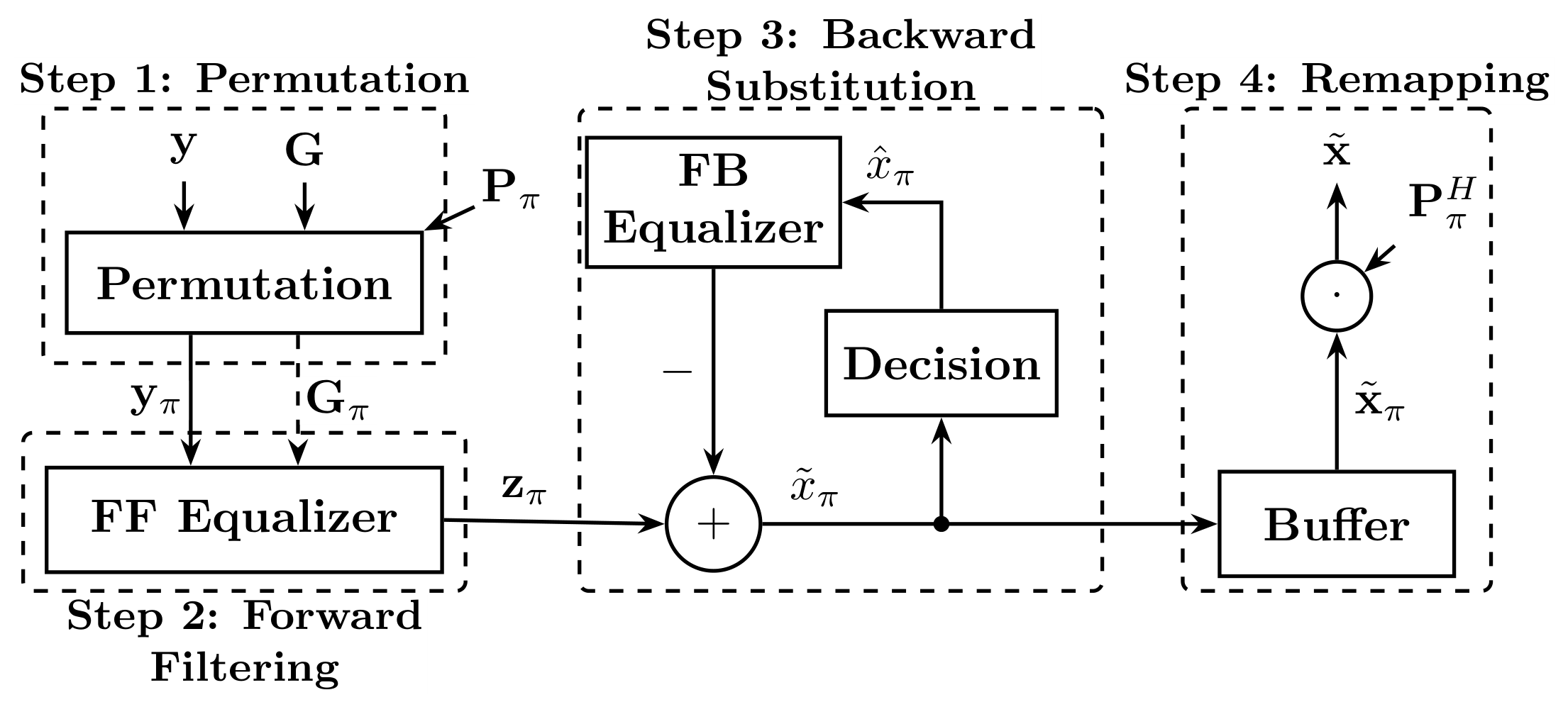
Figure 2.
Descriptive normalized expected majorization gaps across orderings, where , and is the equal-pivot reference (, signal-to-noise ratio (SNR) dB, 4-path Rayleigh).
Figure 2.
Descriptive normalized expected majorization gaps across orderings, where , and is the equal-pivot reference (, signal-to-noise ratio (SNR) dB, 4-path Rayleigh).
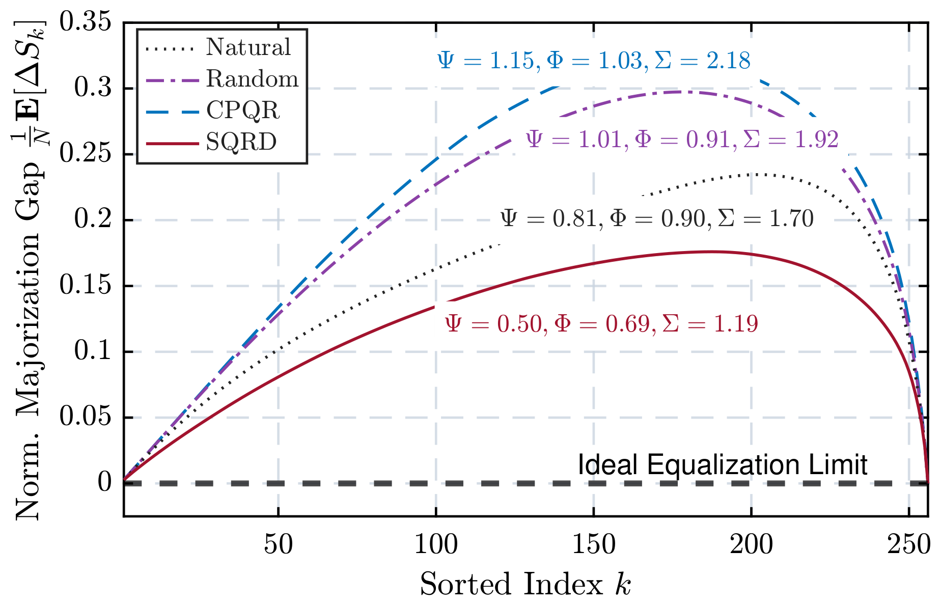
Figure 3.
EG flow: initialization, node selection, and neighbor update.
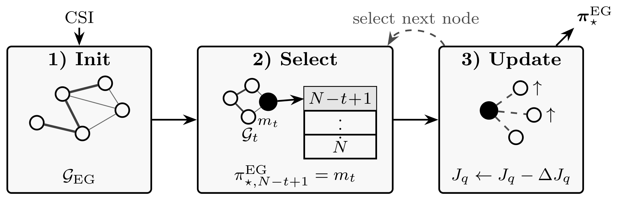
Figure 4.
FF disturbance, FB error, and reconstructed-SINR profiles for different orderings (, quadrature phase-shift keying (QPSK), dB, 4-path Rayleigh); “EG (Prop.)” denotes the proposed EG ordering.
Figure 4.
FF disturbance, FB error, and reconstructed-SINR profiles for different orderings (, quadrature phase-shift keying (QPSK), dB, 4-path Rayleigh); “EG (Prop.)” denotes the proposed EG ordering.
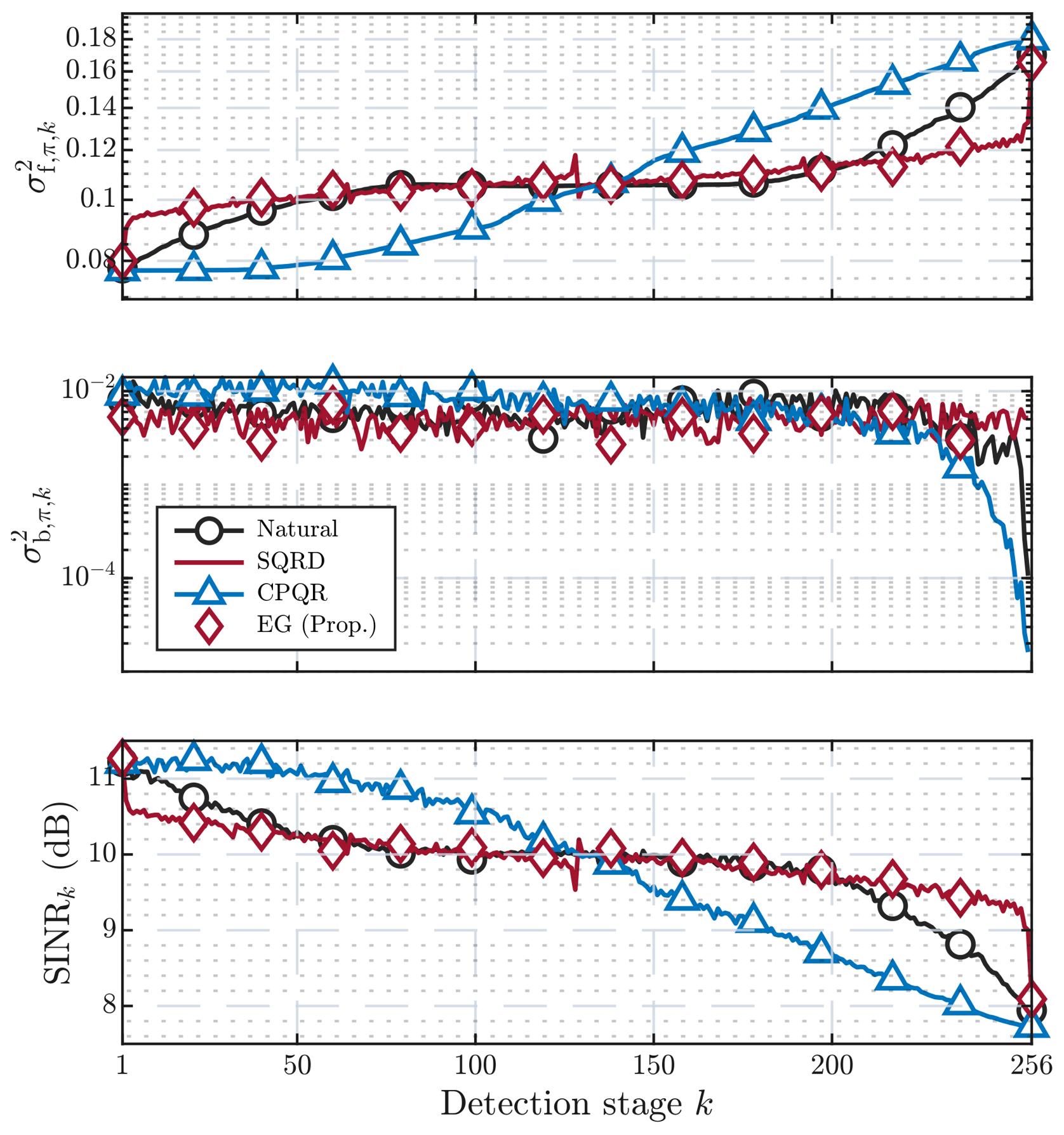
Figure 5.
Block diagram of P-MBDFE with EG-based base ordering and KT-based branch selection from shift/reversal-generated branches.
Figure 5.
Block diagram of P-MBDFE with EG-based base ordering and KT-based branch selection from shift/reversal-generated branches.
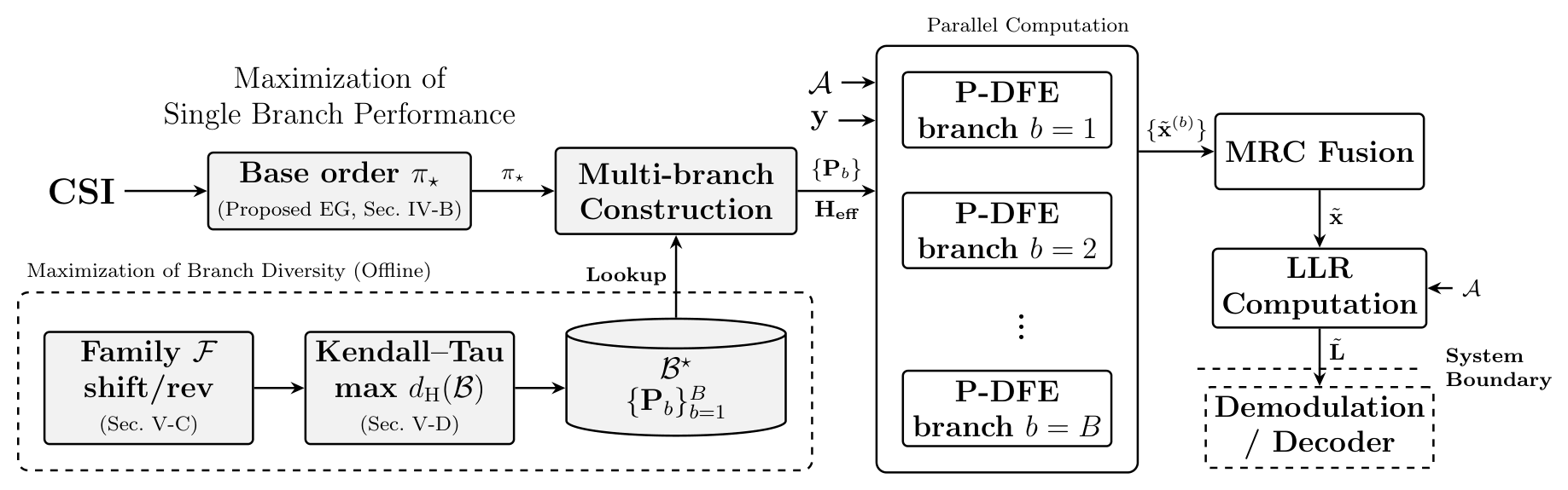
Figure 6.
Ensemble-averaged sorted stage-wise SINR profiles of shifted and reversed EG orderings against the base (, QPSK, dB, 4-path Rayleigh); the dashed diagonal denotes exact profile preservation.
Figure 6.
Ensemble-averaged sorted stage-wise SINR profiles of shifted and reversed EG orderings against the base (, QPSK, dB, 4-path Rayleigh); the dashed diagonal denotes exact profile preservation.
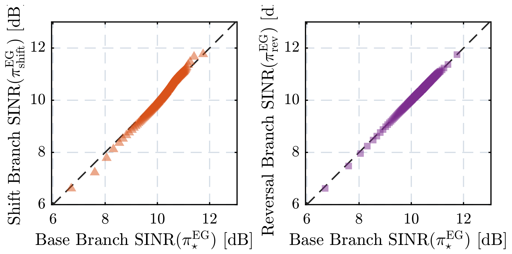
Figure 7.
Undetected and detected symbol sets under natural, reverse, and arbitrary detection orders.
Figure 7.
Undetected and detected symbol sets under natural, reverse, and arbitrary detection orders.
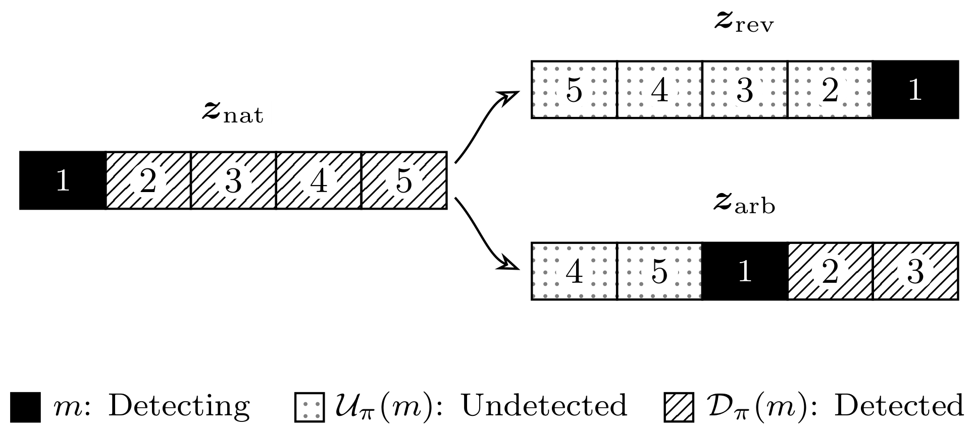
Figure 8.
Empirical actual correlation sum versus harmonic mean KT distance for random 4-branch subsets and the proposed P-QDFE configuration.
Figure 8.
Empirical actual correlation sum versus harmonic mean KT distance for random 4-branch subsets and the proposed P-QDFE configuration.
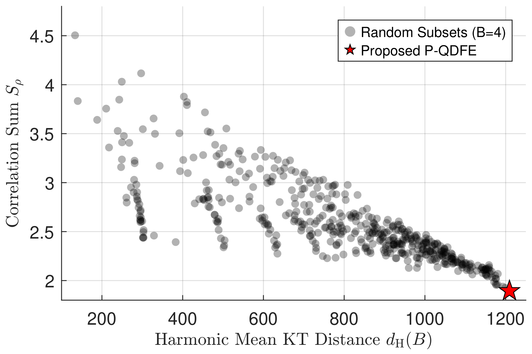
Figure 9.
Uncoded BER and EG complexity trade-offs under fractional delay-Doppler shifts: (a) single-branch ordering gain with , where “Real” denotes decision-directed detection; (b) multi-branch gain with , where “Bi” and “Quad” denote two- and four-branch receivers; (c) EG pruning trade-off while sweeping L.
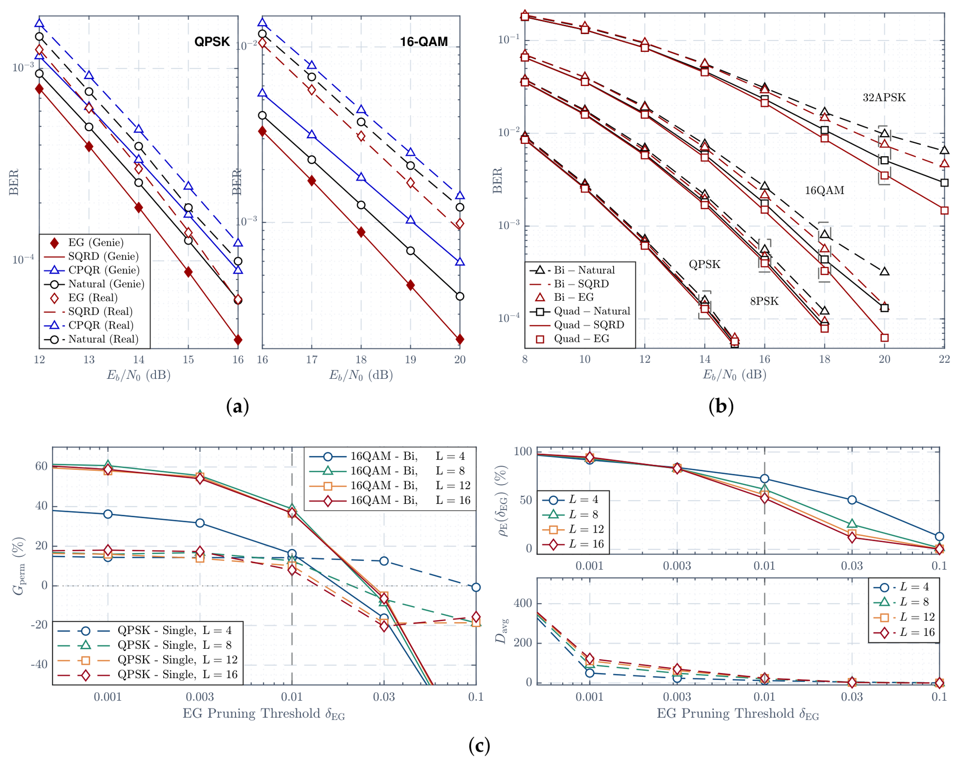
Figure 10.
Uncoded BER under ideal sparse integer delay-Doppler channels (L = 8); MPA and OAMP use I = 20 and I = 8 iterations, respectively, and the matched-filter bound (MFB) is also shown.
Figure 10.
Uncoded BER under ideal sparse integer delay-Doppler channels (L = 8); MPA and OAMP use I = 20 and I = 8 iterations, respectively, and the matched-filter bound (MFB) is also shown.
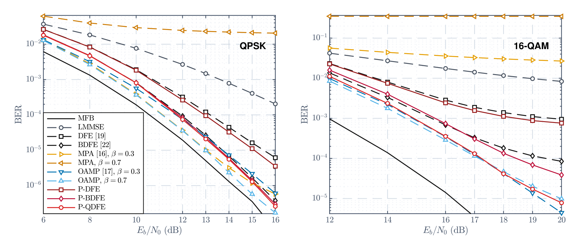
Figure 11.
Uncoded BER with 16QAM under the 24-tap 3GPP TDL-C high-speed channel [35] at 360 km/h: (a) perfect CSI; (b) perturbed CSI.
Figure 11.
Uncoded BER with 16QAM under the 24-tap 3GPP TDL-C high-speed channel [35] at 360 km/h: (a) perfect CSI; (b) perturbed CSI.
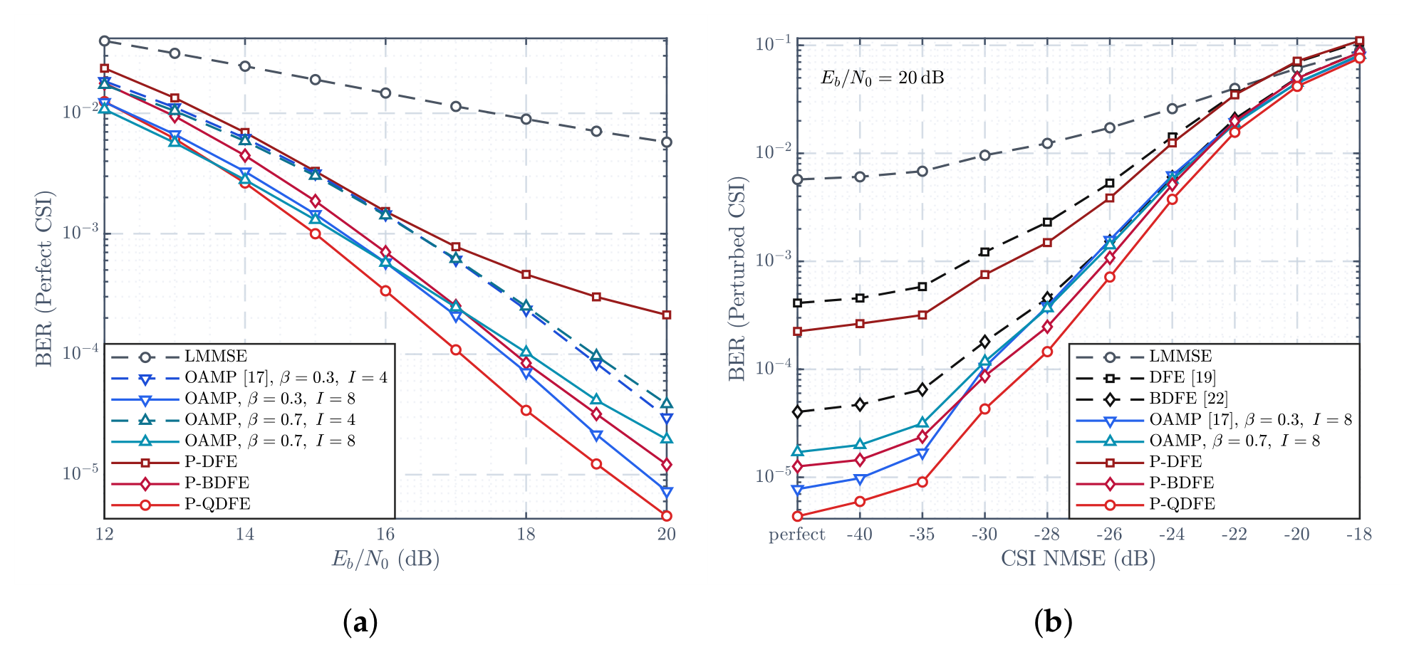
Figure 12.
Uncoded and NR LDPC BG2-coded BER under 16QAM fractional Doppler (, ; OAMP: , ).
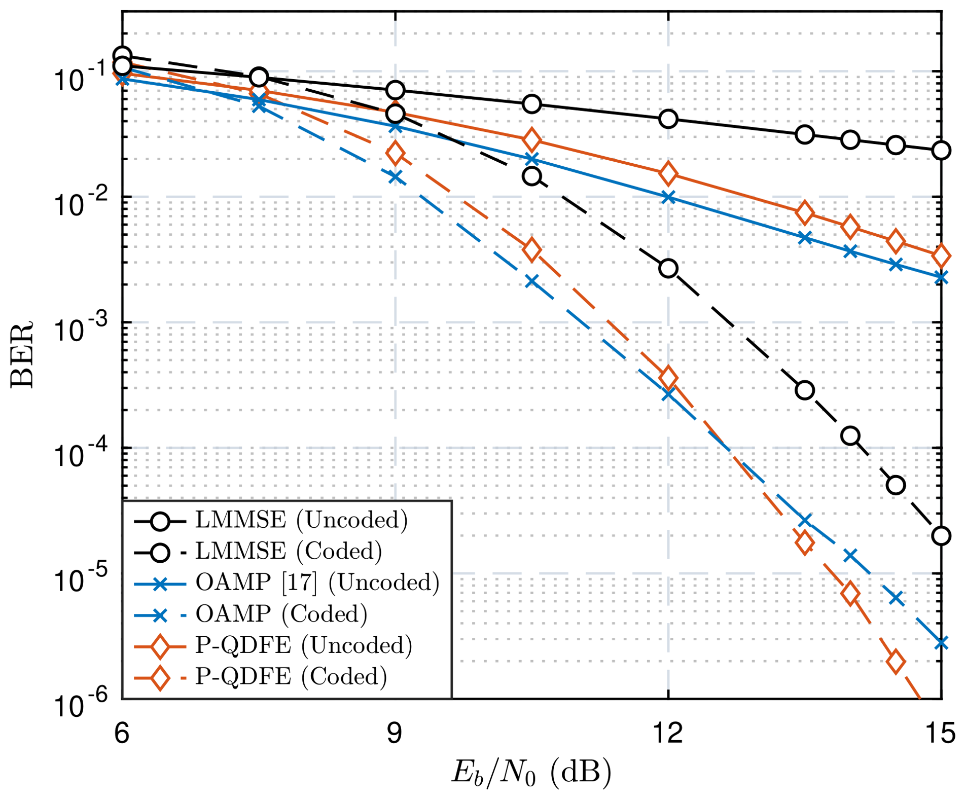
Figure 13.
ICHOL-threshold trade-off for coded BER and arithmetic-mean retained degree under integer (Int.) and fractional (Frac.) Doppler (, , 16QAM, dB).
Figure 13.
ICHOL-threshold trade-off for coded BER and arithmetic-mean retained degree under integer (Int.) and fractional (Frac.) Doppler (, , 16QAM, dB).
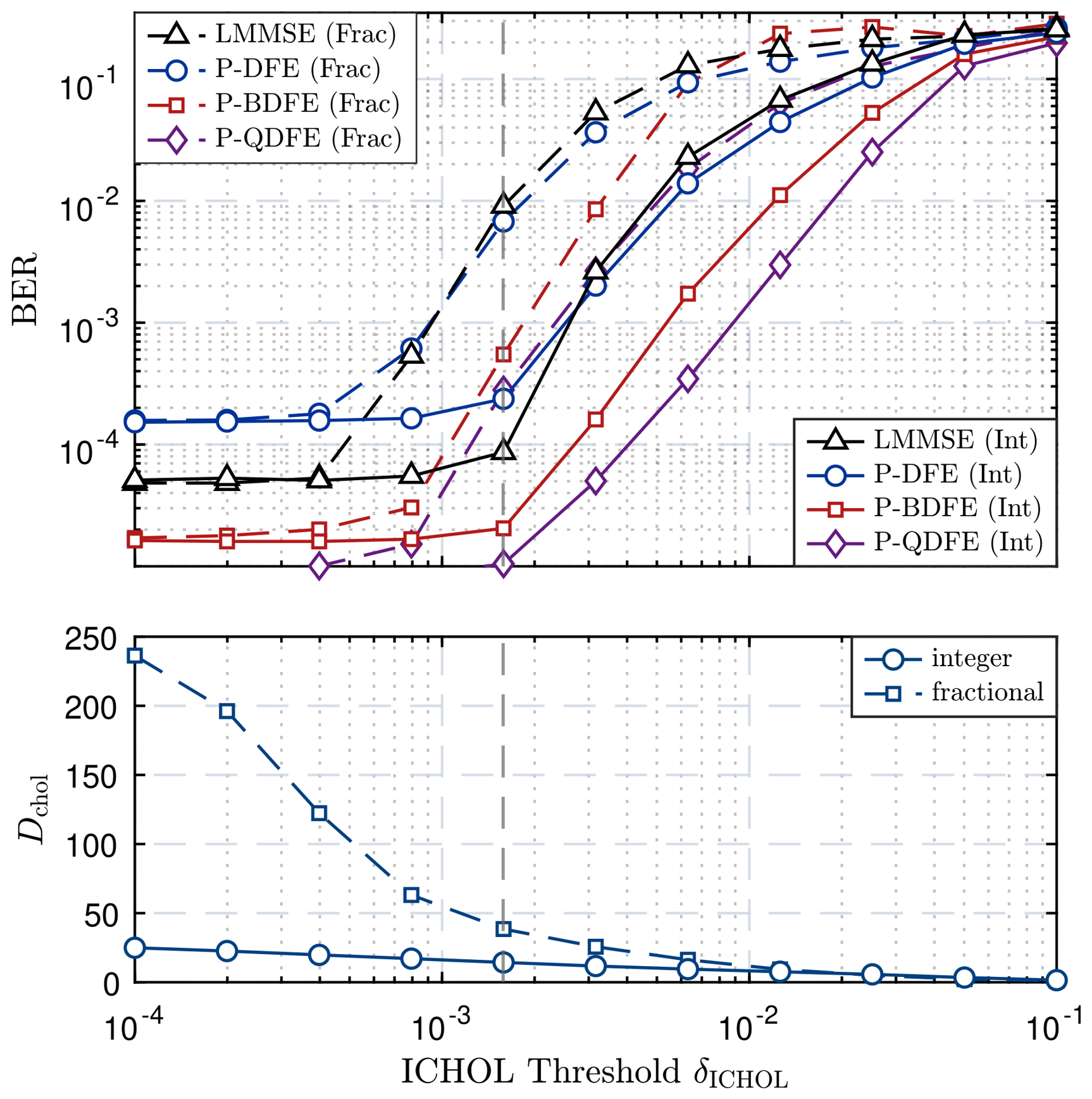
Figure 14.
Critical-path complexity of LMMSE (ICHOL), MPA, OAMP, and sequential (Seq.)/parallel (Para.) P-QDFE (, RMS-degree proxy , 16QAM, ).
Figure 14.
Critical-path complexity of LMMSE (ICHOL), MPA, OAMP, and sequential (Seq.)/parallel (Para.) P-QDFE (, RMS-degree proxy , 16QAM, ).
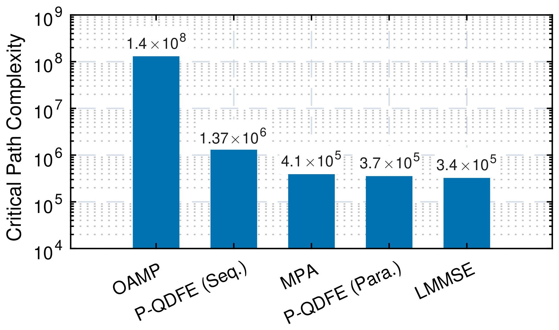

Table 1.
Summary of Main Quantities
| Symbol | Description |
|---|---|
| Permutation Model | |
| , | Physical and detection-stage domains. |
| , | Stage order and physical symbol at stage k. |
| Rank map to detection stage. | |
| Permutation matrix for . | |
| P-DFE Model | |
| , , , | Gram matrices, noise regularization, and unbiasing factor. |
| , | Unit-lower and diagonal factors of . |
| , | Diagonal pivot and triangular coupling coefficient. |
| , | Stage-wise disturbance and propagated-error variances. |
| Stage-wise effective SINR. | |
| EG Ordering | |
| , , | EG Gram matrix, graph, and retained edge set. |
| Residual EG graph at iteration t. | |
| , , , | EG edge weight, threshold, energy ratio, and average degree. |
| , | Remaining symbol set and in-/out-neighbor sets. |
| , | Residual interference power and local SINR key. |
| P-MBDFE Model | |
| B, , | Branch count, candidate family, and optimal branch set. |
| , , | Weight, branch mean-square error (MSE), and physical error correlation. |
| , | Undetected and detected sets for symbol m. |
| , , | KT distance, fraction of symbol pairs with the same relative detection order, and harmonic mean. |
| ICHOL threshold; zero retains the complete elimination graph. | |
Table 2.
3rd Generation Partnership Project (3GPP) tapped-delay-line C (TDL-C) configuration for Figure 11.
Table 2.
3rd Generation Partnership Project (3GPP) tapped-delay-line C (TDL-C) configuration for Figure 11.
| Parameter | Setting |
|---|---|
| Channel profile | TDL-C, 24 taps, Technical Report (TR) 38.901 Table 7.7.2-3 [35] |
| Delay scaling | , ns |
| AFDM grid | , kHz, ns |
| Delay support | , ns, |
| Mobility | km/h, GHz, |
| kHz, | |
| CSI perturbation | sweep, , |
Table 3.
NGMI sensitivity to KT-penalty scale
| Avg. NGMI (10/13/16 dB) |
||||||
| Gap to Best |
Table 4.
16QAM soft-output NGMI with KT-penalty calibration
| NGMI | NGMI Gain | ||||
|---|---|---|---|---|---|
| Unbiased LMMSE |
P-QDFE No correlation |
P-QDFE KT-calibrated |
vs. no correlation |
vs. LMMSE |
|
| 8 | |||||
| 10 | |||||
| 12 | |||||
| 14 | |||||
| 16 | |||||
| 18 | |||||
Disclaimer/Publisher’s Note: The statements, opinions and data contained in all publications are solely those of the individual author(s) and contributor(s) and not of MDPI and/or the editor(s). MDPI and/or the editor(s) disclaim responsibility for any injury to people or property resulting from any ideas, methods, instructions or products referred to in the content. |
© 2026 by the authors. Licensee MDPI, Basel, Switzerland. This article is an open access article distributed under the terms and conditions of the Creative Commons Attribution (CC BY) license (http://creativecommons.org/licenses/by/4.0/).
Copyright: This open access article is published under a Creative Commons CC BY 4.0 license, which permit the free download, distribution, and reuse, provided that the author and preprint are cited in any reuse.