

Submitted:
09 October 2026
Posted:
10 October 2026
You are already at the latest version
Abstract
We describe and test a complete construction design for the Great Pyramid of Khufu. Each course is finished, casing included, before the next. Thirty-five tiers (mastabas) of dry-laid block stand against the four faces, their heights generally following the quarry beds. Two back-and-forth ramps at 1:8 climb the east and south faces. The east ramp is 11 m wide to the King's Chamber floor and 9 m to 65.9 m, for the granite beams, and carries two lanes of sledges below 65.9 m. Two short rubble ramps on the north and west faces serve the lowest courses. The men come down a ramp on the west face and the empty sledges, tethered in threes, down a timber chute. After the pyramidion is set, the tiers are taken down from the top while the face is dressed, and their blocks are reused.We assume the stone is waiting at the foot of the ramps and simulate the construction itself, course by course: the haul up the ramps, the haul across the course, the setting of core and casing, the setting out of each course and the granite beams. A minute-by-minute route model, which reproduces the result of our first paper, feeds a course model built on Petrie's course table. For each unmeasured value we give an expected case, our best reasoning, and a worst case. With every unmeasured value at its worst, the lift takes 22.1 years and the whole work 24.5, within the 27 years attested by the Diary of Merer. With expected values the ramps and the setting have a capacity of 12.0 years of lift; this theoretical figure gives a scale, not an estimate of the build. The tiers and ramps hold 268,800 m³ of block, 10.4 per cent of the pyramid. The work is about 47 million man-days whatever the pace, so the reign sets the size of the camp: about 5,800 men on average for a build of 27 years and 6,900 for 23 years. The result depends most on the time a turn and a loading take at the ramps.
Keywords:
Great Pyramid
; Khufu
; construction ramps
; external tiers
; mastabas
; Old Kingdom
; construction logistics
; discrete-event simulation
; experimental archaeology
1. Introduction
The Great Pyramid holds about 2.4 million m3 of block over a core of bedrock, raised to 146.6 m within a reign of 23 to 27 years. No text says how the blocks were raised. Each proposed solution meets a difficulty. A straight ramp to the top would hold about as much stone as the pyramid. A spiral ramp on the faces hides the corners, which the builders had to sight to keep the geometry. An internal ramp is narrow and turns at right angles. And no large ramp debris survives at Giza.
Our first paper (Dubray and Choi 2026) modelled the whole site as a discrete-event simulation. Its pace was set by the quarry: about 283 m3 of block a working day from the face of the main quarry. Other quarry fields were worked on the plateau at the same time (Klemm and Klemm 2010), so that limit is a matter of men, not of rock.
This paper takes the stone as given at the foot of the ramps and asks how fast one complete construction design can build, and what it requires in men, sledges, water and food. The design is the reconstruction of Choi (2021), developed with the tiers, ramps and finishing described below. We test it with a minute-by-minute route model and a course model, and report its stone cost, the step that sets the pace at each height, its finishing and its camp.
2. Previous Work
2.1. Ramp Theories
Straight, spiral and internal ramps have been argued for more than a century (Lauer 1960; Arnold 1991; Lehner 1997; Houdin 2006). Dunham (1956) placed four ramps on the faces at 1:8, about 3 m wide, three up and one down, with the rope turning round braced posts at the corners. Goyon (1977) proposed a ramp wound round the pyramid on a separate structure of other materials. Müller-Römer (2011) published a quantified stepped-core model with steep ramps on the step platforms of all four faces. Rosell Roig (2026) rejects face ramps because they obstruct survey control and perimeter access. Stepped cores and accretion layers are attested in the Third and early Fourth Dynasties, at Meidum and in the building phases of the Bent Pyramid (Monnier and Puchkov 2016; Monnier 2017). We keep ramps on the faces, as Dunham did, but place them on external tiers that ring all four faces and serve the survey of the casing.
A stepped core with steep ramps. Müller-Römer (2011) builds the core of Khufu’s pyramid as twelve steps of about 11 m in horizontal courses. Ramps at 2:1 stand on the step platforms of all four faces, with a rope roller at each ramp head and 45 men to a load. A working platform of mud brick with stone flanks then carries the backing and the casing. He reports that in the robbers’ tunnel the core masonry changes abruptly at course 7 (7.06 m) and reads this as the face of the first step. Run under the rules of this paper with his values, the scheme gives his 24.5 years for the whole work; passing each block over the ramps of the lower steps does not lower his rate. About half of his 12-minute unit is handling (fastening, release, return of the rope), which has not been measured. With the handling raised by half, the work takes 27.0 to 29.3 years; doubled, 31.4 to 34.1. On a 2:1 ramp a 45 t beam needs 237 to 296 kN of rope pull, more than his strongest roller (138 kN), so the granite needs a separate route. His platform is of the attested ramp materials; by his figure for Menkaure, its removal leaves debris of about a quarter of the pyramid’s volume. In the design of this paper the masonry is laid in horizontal courses over a bedrock knoll carved in steps of 3 m (Section 3). The change at 7.06 m lies within the height of that knoll, which offers another reading of it; the observation has not been described by a second observer.
2.2. Hauling
The Djehutihotep scene, of the Twelfth Dynasty, shows a colossus of about 70 to 80 t on a sledge, hauled on four ropes by 172 men, with water poured before it to wet the track (Monnier 2020b). The figures give about 400 kg a man, close to the mean of 340 kg a man that Delvaux (2018) finds in other Egyptian scenes. On the flat, 400 kg a man at 300 N implies a friction near 0.08. No measured friction exists for a sledge on wet Nile mud: Chevrier (1970) implies 0.07 to 0.08, Fall et al. (2014) give 0.30 to 0.37 for wet sand, and modelling papers assume 0.20 to 0.25. Sustained pull is 160 to 250 N a man at the median and up to 430 N in the strongest decile (Snook and Ciriello 1991). We take 0.2 and 300 N as central values, cautious against the scenes, and test the range in Section 14.
2.3. Quarries and the Supply of Stone
Lehner (1985) estimates the main quarry south of the pyramid at 2.76 million m3, against 2.59 million m3 for the pyramid; quarrying waste may reach 30 per cent (AERA). Klemm and Klemm (2010) trace the core to several quarry fields south and south-east of the pyramid, so the face of the main quarry does not cap the rate. The Diary of Merer records fine Tura limestone shipped to Giza in year 26 or 27 of Khufu (Tallet 2017). We take the stone as waiting at the foot of the ramps and report the quarry rate that each pace requires.
2.4. Archaeological Evidence of Ramps
The only measured Old Kingdom haul ramp is at Hatnub, of the reign of Khufu: a central ramp between two stairs, 7.8 m wide in all, about 80 m long and up to 20 per cent, with post holes on its sides (Gourdon and Enmarch 2018; Brichieri-Colombi 2019); Brichieri-Colombi (2019) reads the posts as bollards. At Sinki, a small step pyramid at South Abydos probably of the Third Dynasty, a ramp rises against each of the four faces (Dreyer and Swelim 1982). At Lisht, inclined brick construction ramps with transverse timbers survive at the pyramids of Amenemhat I and Senwosret I (Arnold 1991). Hawass (1998) describes a ramp of limestone chips, gypsum and tafla south-west of the Great Pyramid. Lehner (1985) reads the chip, gypsum and tafla deposits in the main quarry as dismantled ramps; Müller-Römer (2011) and Klemm and Klemm (2010) find too little ramp debris for large ramps. A design whose tiers are dry-laid block, taken down and reused, leaves no such dump; Section 15 turns this into tests.
3. The Construction Sequence
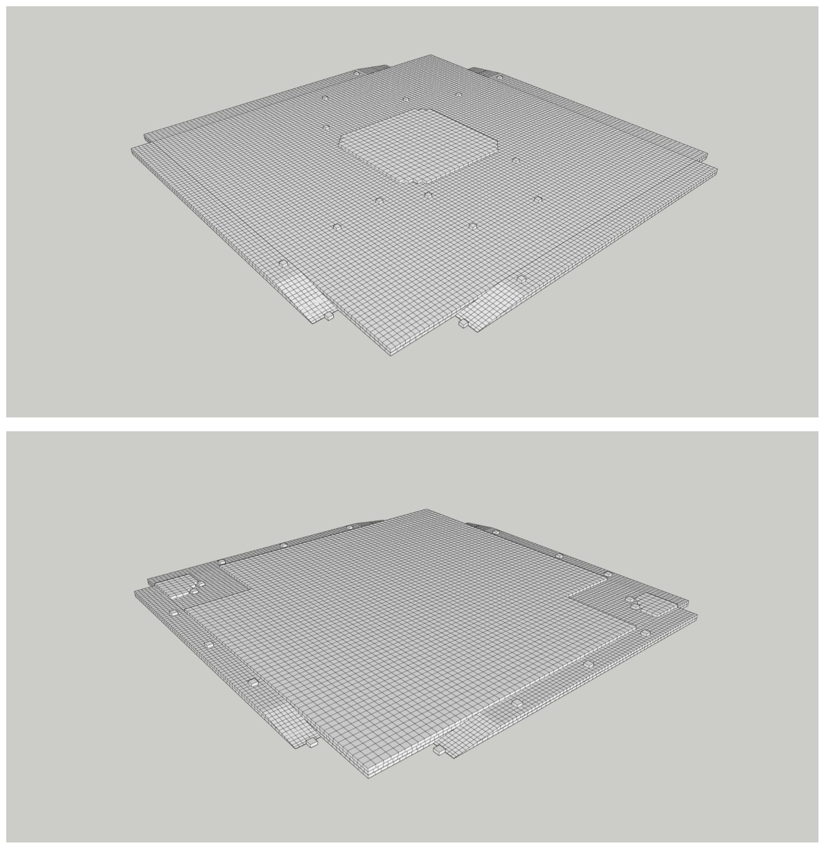
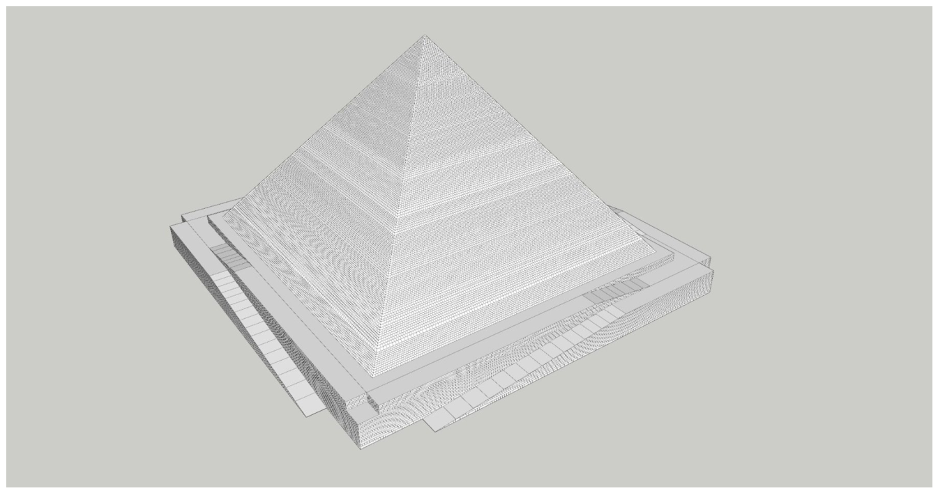
Each course is completed, casing included, before the next (Appendix A shows the whole sequence). The core is laid from the centre outward, the backing and casing last as the outer ring, and the landings where the ramps arrive are filled at the end of the course. The casing therefore rises with the core, and no terrace in the pyramid itself has to be closed at the end. Müller-Römer (2008) also completes the backing of a layer before its casing. Lines drawn on the beds of the casing and of the core show where each stone was to go, and Petrie (1883, §168) concludes that the masons planned the casing course by course. Where the core of the great pyramids of this period can be seen, its masonry is irregular (Monnier 2020a).
Figure 1.
One course in two moments: the core laid from the centre outward (top); the backing and casing laid as the outer ring, with the landings where the ramps arrive still open (bottom).
Figure 1.
One course in two moments: the core laid from the centre outward (top); the backing and casing laid as the outer ring, with the landings where the ramps arrive still open (bottom).
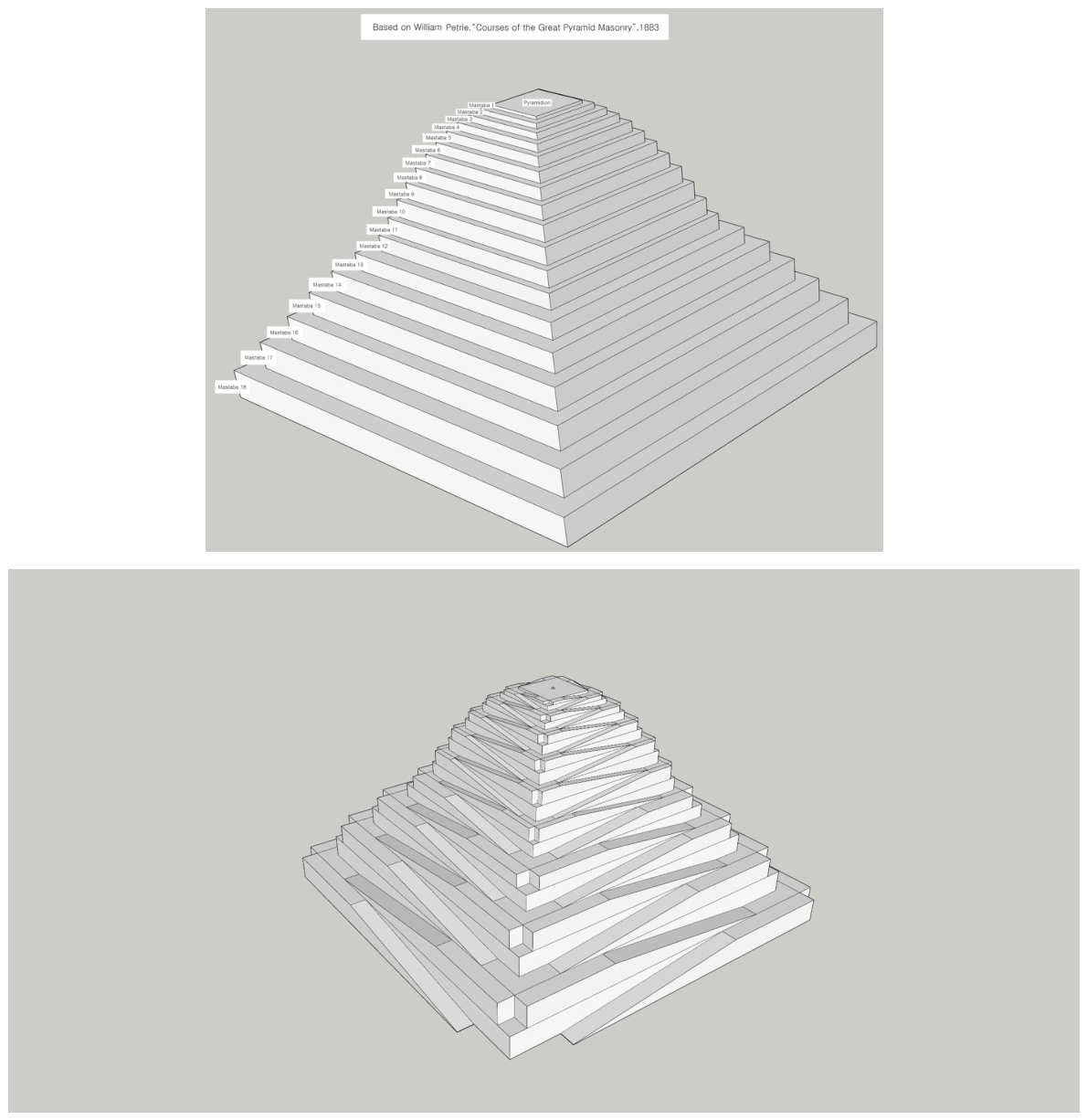
Against the four faces stand external tiers of dry-laid block with vertical outer walls. Their heights generally follow the quarry beds: the eighteen tiers, or mastabas, of the reconstruction (Choi 2021) follow Petrie’s courses, and each is split in two, except the last, so that every terrace is at least 1 m deep, the depth a mason needs to dress the face. The result is 35 tiers, 7.7 m high at the base and 1.6 m at the top. Where a bed is too thin, two beds are combined into one tier.
| H]llll Tier (reconstruction) | Height (m) | Split | Top of tier (m) |
| 1 | 15.47 | in two | 15.5 |
| 2 | 14.70 | in two | 30.2 |
| 3 | 12.97 | in two | 43.1 |
| 4 | 12.20 | in two | 55.3 |
| 5 | 10.56 | in two | 65.9 |
| 6 | 8.89 | in two | 74.8 |
| 7 | 8.50 | in two | 83.3 |
| 8 | 8.66 | in two | 91.9 |
| 9 | 9.03 | in two | 101.0 |
| 10 | 8.44 | in two | 109.4 |
| 11 | 7.26 | in two | 116.7 |
| 12 | 6.39 | in two | 123.1 |
| 13 | 5.65 | in two | 128.7 |
| 14 | 5.25 | in two | 134.0 |
| 15 | 4.02 | in two | 138.0 |
| 16 | 3.39 | in two | 141.4 |
| 17 | 2.70 | in two | 144.1 |
| 18 | 1.56 | whole | 145.6 |
Figure 2.
The eighteen tiers of the reconstruction, set on Petrie’s courses (top), and the tiers ringing the four faces (bottom).
Figure 2.
The eighteen tiers of the reconstruction, set on Petrie’s courses (top), and the tiers ringing the four faces (bottom).
The terrace at the top of a tier of height r, measured beyond the face, is at least k · r deep, with k = 0.7857, the cotangent of the face angle. At height h within the tier its depth is d(h) = max(w, k · r) − k · (r − h), where w is the width of a ramp on that face. The outer wall of each tier stands on the base line of the face below, so above the first tier the whole structure stands inside the pyramid’s footprint (Figure 3). The tiers retain no fill. Each course of a tier is laid on horizontal beds: on the course below and, at its inner end, on the rough face of the casing behind it, not yet dressed. At Menkaure the casing blocks keep their extra stock except around the entrance and behind the offering chapel (Arnold 1991). Every course bears down and none pushes outward, so the vertical outer wall needs no batter.
Site plan. On the east face, the 11 m ramp makes the first tier stand 4.9 m beyond the base at ground level, and the first ramp leg reaches 15.9 m from the base. The inner enclosure wall lies 10.2 m from the base on the east and north and a little less on the south and west (Maragioglio and Rinaldi 1965, 66). The court pavement and the enclosure wall were therefore laid after the lowest tier was dismantled, at the end of the work; Lehner (1983) places the court pavement at the end of the project and the dressing of the casing from the top down as the ramps were removed. The queens’ pyramids (G1-a about 61 m from the pyramid, Maragioglio and Rinaldi 1965, 76; G1-d about 25.5 m south-east of the south-east corner, Hawass 1996) and the south boat pits, outside the enclosure wall (Maragioglio and Rinaldi 1965, 70), are clear of every ramp. The east ramp starts at a corner. Its legs, at most about 62 m long, stay clear of the mortuary temple, about 54 m wide in the middle of the east face, and of its two boat pits, more than 20 m from the base (Maragioglio and Rinaldi 1965, pl. 9). The temple can therefore be built while the tiers stand, except the part that enters the court, built with the court after the lowest tier comes down. Holes cut in the rock along all four sides, about six cubits from the base, were used to align it and were filled with stones and mortar before the pavement was laid (Maragioglio and Rinaldi 1965, 66; Lehner 1983). The first tier covers them on the east face, so they served the setting out before the tiers rose.
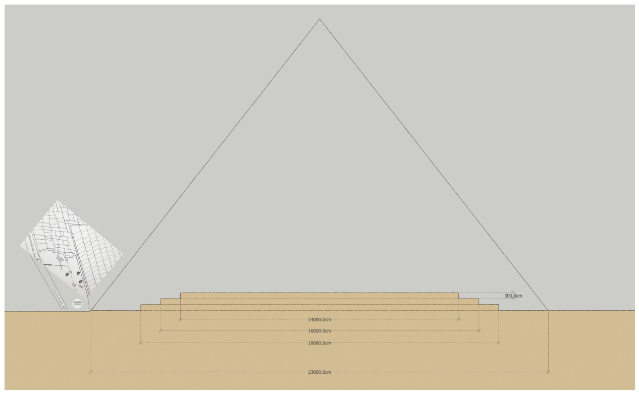
Bedrock. The pyramid stands on a hill of rock that was cut back into steps; only a strip round the perimeter was levelled (Maragioglio and Rinaldi 1965; Lehner and Hawass 2017). The rock reaches almost 6 m above the base at the Grotto. It is at least 3 m above the base in the descending passage and about 7 m where the service shaft enters it; the form and extent of the knoll are unknown (Maragioglio and Rinaldi 1965, 12). Petrie (1883, §167) saw the rock rising in steps inside the masonry to some 25 feet (7.6 m). We model three steps of 3 m, 180, 160 and 140 m wide, to 9 m; in the reconstruction the protruding rock is 8 to 9 m high (Choi 2021), and the widths are an assumption. This is the expected case; the worst case, a rock pyramid 7 m high (first paper), adds 0.3 years to the lift (Section 14). The steps hold about 233,000 m3 that need not be quarried or lifted, and the waste of cutting them supplies the rubble ramps of Section 4.
Figure 4.
The bedrock knoll under the pyramid in the reconstruction: three steps of 3 m, 180, 160 and 140 m wide, on the 230 m base; inset, the bed of the enclosure wall at 20 cubits (10.5 m). Drawing: Choi.
Figure 4.
The bedrock knoll under the pyramid in the reconstruction: three steps of 3 m, 180, 160 and 140 m wide, on the 230 m base; inset, the bed of the enclosure wall at 20 cubits (10.5 m). Drawing: Choi.
4. The Ramps
Two sledge ramps at 1:8 (about 7 degrees) carry the blocks up. Each ramp goes back and forth on its face: a leg climbs one tier, and the next leg starts at the turn of the leg below. A leg is r/g long for a tier of height r and grade g, from 62 m on the lowest tier to 12.5 m on the highest. The east ramp carries two lanes of sledges where it is 11 or 9 m wide, below 65.9 m; the south ramp carries one. Below 15.5 m, two short rubble ramps on the north and west faces add a lane each for the lowest courses, which hold the most stone. They are cleared once the courses rise above them, and their rubble goes back to the dumps of the plateau.
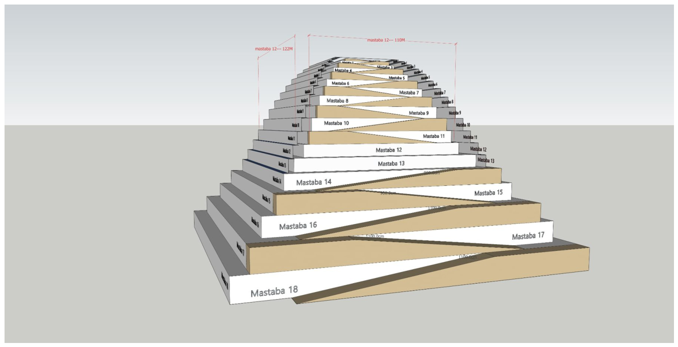
Figure 5.
The back-and-forth ramps on the tiers, one leg per tier.
| H]lllll Ramp | Face | Width | Grade | Carries |
| East sledge ramp | east | 11 m to 43.1 m, 9 m to 65.9 m, 4 m above | 1:8 | blocks up, two lanes below 65.9 m and one above; the granite beams |
| South sledge ramp | south | 4 m, full height | 1:8 | blocks up, one lane |
| Rubble ramps | north and west | 4 m, to 15.5 m | 1:8 | blocks up for the lowest courses, one lane each |
| Men’s ramp | west | 2 m | 1:4 | empty crews down |
| Timber chute | one face | narrow | 1:2 | empty sledges down in trains of three, on brake ropes |
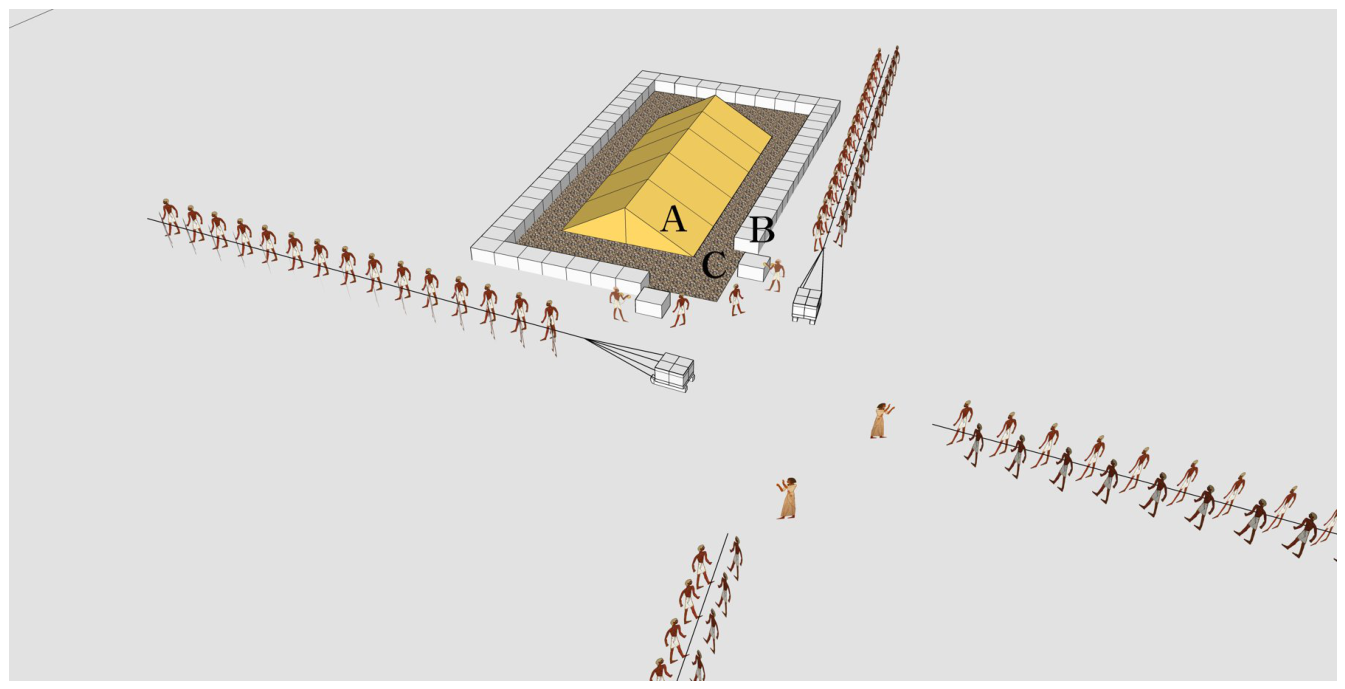
The east ramp is wide below 65.9 m for the granite beams of the King’s Chamber and the relieving chambers (Section 9). A 54 t beam on 1:8 needs about 570 men; a 4 m ramp cannot hold them. Where it is wide, the ramp also carries two lanes of sledges.
Figure 6.
Granite beams hauled to the King’s Chamber level (A, B, C: beams).
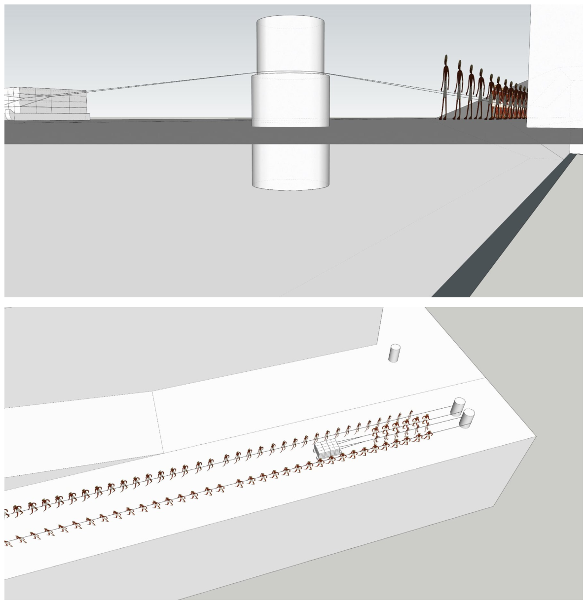
At each turn the rope bears on a fixed stone post, a cylinder about 1.5 m across and several tonnes, its lowest part sunk into the terrace. The crew is already on the next leg, walking back the other way; the rope slides half a turn round the post and the sledge does not stop. On the level terrace the sledge needs about two thirds of its pull on the ramp, and the half turn raises it by 1.9 to 3.0 times for a rope friction of 0.2 to 0.35: for the few seconds of the swing the crew pulls 1.2 to 2.0 times its pull on the ramp, and at the upper end the turn needs extra men or a wetted rope. Where a leg turns the corner of the pyramid above 138 m (Section 10), the wrap is a quarter turn and the rise 1.4 to 1.7 times. We take a continuous turn of about 30 s.
Figure 7.
The turn: the rope bears on the fixed stone post (top); the crew is already on the next leg while the sledge comes round (bottom).
Figure 7.
The turn: the rope bears on the fixed stone post (top); the crew is already on the next leg while the sledge comes round (bottom).
The crews haul with their hands on the rope, one file a rope, at about 0.8 m a man. A 2.5 t block on 1:8 at a friction of 0.2 needs 26 men; a 1.4 t block near the top needs 15. A man sustains about 75 W over a working day (West, Gallagher and Waters 2014). Pulling 300 N while lifting his own weight up 1:8, he climbs at about 0.2 m/s, and this sets the speed of a loaded sledge on the ramps. A resting sledge holds itself on 1:8 at a friction of 0.2 (the slope, 0.125, is below the friction); at 0.15 it holds only just, and chocks are needed on a slick surface.
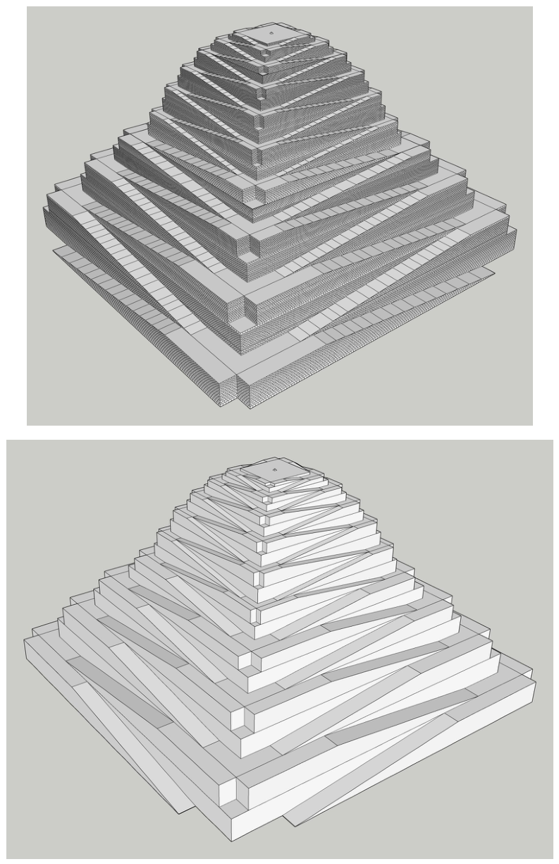
Every block leaves an empty sledge on the deck. The empty crews walk along the four-face tiers to the men’s ramp on the west. The empty sledges, about 0.3 t each, go down a timber chute at 1:2 in trains of three, held on brake ropes 20 m apart: about 1,800 sledges a day, for about 33 m3 of planking and 3 kN of braking a train. One sledge at a time, the chute would carry 600 a day and would set the pace below 65.9 m.
Figure 8.
The tiers and the back-and-forth ramps on the four faces, in block courses (a) and in outline (b). Drawings: Choi.
Figure 8.
The tiers and the back-and-forth ramps on the four faces, in block courses (a) and in outline (b). Drawings: Choi.
5. The Route Model and Its Validation
The route model is a deterministic simulation at six-second ticks, run on the polytrion engine (Cognitive Fab 2026). A route runs from the foot of a ramp to the deck of the course being laid. Each crew with its sledge is a train of fixed length on a lane: 0.8 m a man along the rope, a 3 m sledge and a 2 m gap to the crew ahead. The gates are the loading point at the foot (2 min a load), the turns (about 30 s each) and the lanes. Loaded sledges move at 11.7 m a minute (0.195 m/s, Section 4) and empty crews walk down at 72 m a minute. The working day is 600 minutes. At the ramp head the sledge is drawn onto the deck, clear of the lane, before the crew casts off. In the validation a load is 1.1 m3, as in the first paper; elsewhere a sledge carries one block, its mass from Petrie’s course table; crews are sized at 300 N a man and a friction of 0.2.
A load counts as delivered only if it reaches the deck before the end of the day: a loaded sledge is not left on the ramp overnight. This is a cautious rule. If loads could be chocked on the ramp and finished in the morning, a lane would deliver its full dispatch at every height.
We first ran the model in the configuration of the first paper: a four-minute dispatch, two lanes a route below 43 m, one above, no corners.
| H]lll Quantity | First paper | Route model |
| Loads a lane a day | 150 dispatched | 145 delivered |
| Lanes needed | 1.7 | 1.75 |
| Lifting days, 1 route below 43 m + 1 above | 11,892 | 12,186 |
| Lifting days, 1 + 2 | 9,044 | 9,044 |
| Lifting days, 1 + 3 | 9,044 | 9,044 |
| Lifting days, 2 + 2 | 9,044 | 9,044 |
The differences come from the loads still on the ramp at the end of the day, which the route model does not count. With enough lanes the model reproduces the first paper’s 9,044 lifting days exactly.
6. The Cost of the Tiers
The tiers and ramps of the base case hold 268,800 m3 of block, 10.4 per cent of the pyramid (2.59 million m3). The two rubble ramps of the lowest courses add about 7,700 m3 of waste from cutting the bedrock, not block.
| H]ll Part | m3 |
| Tier rings (35 tiers, four faces, corners counted) | 231,300 |
| East ramp legs (11 m, 9 m, then 4 m) | 23,000 |
| South ramp legs (4 m) | 11,600 |
| West men’s ramp (2 m at 1:4) | 2,900 |
| Total | 268,800 |
The plan area of the tiers at height z is a rectangle with its corners counted, less the pyramid:
where s is the side of the pyramid at z and d is the depth of each face’s tier from Section 3. A ramp leg is a wedge of width w, length r/g and height r. Where no ramp runs, a tier’s section is a triangle of about 0.5 · k · r² a metre of face: it grows with the square of the tier height. The tier height is therefore the main lever on the stone.
| H]lll Design | m3 | Share of the pyramid |
| 18 tiers undivided, east ramp 11 / 9 / 4 m, south 4 m above 65.9 m | 390,000 | 15.0 % |
| 35 tiers, east ramp 11 / 9 / 4 m, south 4 m (base case) | 268,800 | 10.4 % |
| 36 tiers, east and south ramps 4 m | 196,100 | 7.6 % |
| 54 tiers (each tier split in three), east and south ramps 4 m | 152,900 | 5.9 % |
A search over 114,966 variants (tier grouping, ramp faces, ways down) found that the stone keeps falling as the tiers get thinner; only the terrace depth stops it. Splitting every tier in three leaves terraces under 1 m near the top and too little room to haul and turn heavy blocks below the King’s Chamber, so it is kept as a variant. The wide east ramp costs 72,700 m3 on its own, because on thin tiers the whole east terrace must be as deep as the ramp is wide. One ramp alone is never enough: two are the minimum.
A tier built as a block wall round a rubble core saves little. With vertical outer walls a tier is thin, and a dry retaining wall a third of the tier height thick leaves 84 per cent of the section in block. Rubble packing, without mortar, fills the gaps between roughly dressed blocks, so the tiers stay reusable. A fill of rubble would not shorten the work: it is lifted like the block, and it leaves a dump of its own volume, small beside the masons’ chip banks north and south of the pyramid (Petrie 1883, §170).
7. Stone at the Foot of the Ramps
The core is local stone. Klemm and Klemm (2010) match the core blocks by chemistry to the quarry fields south and south-east of the pyramid, and no core sample requires a distant source. Boat transport is recorded for the fine Tura limestone of the casing (Tallet 2017). We therefore bring the core and the tier stone from the plateau, and the casing from the harbour on the east.
The main quarry is about the size of the pyramid alone: 2.76 million m3 gross (AERA, after Lehner), against 2.59 million m3. Net of a quarrying waste of up to 30 per cent, other fields on the plateau were needed in any case (Klemm and Klemm 2010). With several faces worked side by side, the quarry rate is set by the number of quarrymen. We therefore assume that the stone of the pyramid and of the tiers is waiting at the foot of the ramps, stockpiled during the preparation and delivered at a steady rate.
The first paper derived 283 m3 of block a day from an assumed build of 27.5 years. Here the build is not assumed. The course model of Section 8 finds the capacity of the construction; the reign then fixes the quarry rate and the size of the camp (Section 13).
As the tiers come down, the tier blocks go to the next works. The queens’ pyramids G1-a to G1-c belong to the reign of Khufu (Reisner 1942). If they were begun around the middle of the reign, the work then stands at about 56 m and the tiers still stand. The tiers below that height on the north and west faces, which carry no sledge ramp, hold about 85,000 m3, more than the three queens’ pyramids (about 70,500 m3); taken down early, they can supply them, and the lower casing of those faces is then dressed from the ground. The rest go at the end to the mastabas of the cemeteries and the pyramid of Khafre. Dry-laid block, taken down course by course, is ready for reuse; it leaves no ramp dump.
8. The Course: Ramps, Deck and Setting
Each course is built in five steps: setting out, the haul up the ramps, the haul across the course, the setting of the core and the fitting of the casing. The course is finished before the next is set out (Section 3). The course model runs these steps for each of Petrie’s 217 courses, with the stone waiting at the foot. A course takes its setting out plus the longest of the other steps, which run side by side.
Setting out. Levelling the top of the course below and marking the axes and the edge of the next take one day a course. This is an assumption, tested from half a day to three days in Section 14; over 217 courses one day is 0.7 years.
Ramps. One block rides on each sledge. The route model gives the sledges a lane delivers in a day at each height. The base case has two lanes on the east ramp below 65.9 m, one on the south ramp, and one on each rubble ramp below 15.5 m.
Deck. A deck crew of 15 to 40 men takes the sledge from the ramp head, at the middle of the east or south edge, to the block’s place: 103 m on average on the first course, 39 m at 90 m. The deck haul never sets the pace.
Setting. A crew of ten sets a core block in 30 minutes. This is an assumption between the lever experiments: under a minute for a 1.15 t block (Hussey-Pailos 2005) and 1.5 to 2 hours for a step (Isler 2001). The core masonry points to a quick rate: it is of cruder blocks set with gypsum mortar, sometimes with a fill of broken stone (Lehner 1997), and its blocks are not always in contact (Maragioglio and Rinaldi 1965); the care went into the casing. The worst case, 60 crew-minutes, and the setting time at which the work no longer fits the reign are given in Section 14. Each crew needs 6 m of the laying front. Laying the core from the centre outward, as in Section 3, gives a front that grows with the core; over a course it is worth two straight fronts across the course. The casing is fitted along the perimeter at 6 crew-hours a block (first paper), by crews 6 m apart. The passages, the Grand Gallery, the chambers and the shafts add blocks fitted at the casing rate.
| H]llllllll Height (m) | Side (m) | Blocks in the course, pyramid and tiers | Ramps (sledges a day) | Setting (blocks a day) | Course (days) | Sets the pace | Deck haul, mean (m) |
| 0.0 | 230 | 19,340 | 1,360 | 1,786 | 15.2 | ramps | 103 |
| 10.9 | 213 | 41,231 | 1,475 | 1,574 | 29.0 | ramps | 95 |
| 30.2 | 183 | 29,720 | 825 | 1,331 | 37.0 | ramps | 82 |
| 50.4 | 151 | 20,562 | 840 | 1,113 | 25.5 | ramps | 68 |
| 70.7 | 119 | 12,398 | 544 | 844 | 23.8 | ramps | 53 |
| 90.5 | 88 | 7,420 | 530 | 694 | 15.0 | ramps | 39 |
| 110.1 | 57 | 3,159 | 514 | 468 | 7.7 | core setting | 26 |
| 130.3 | 26 | 814 | 496 | 280 | 3.9 | core setting | 11 |
| 140.1 | 10 | 227 | 484 | 71 | 4.2 | casing | 5 |
With expected values the ramps and the setting have a capacity of 3,939 working days of lift, 12.0 years. This is a theoretical figure that gives a scale, not an estimate of the build. The ramps set the pace on 90 per cent of the days. The setting of the core sets it on 7 per cent, near the top, where the course is small and few crews fit. The casing sets it on 3 per cent, in the last courses. With the setting instant, the ramps alone would take 11.0 years. The four lanes below 15.5 m matter because the lowest courses hold the most stone: without the rubble ramps the lift takes 12.8 years.
9. The Granite Beams
The King’s Chamber floor stands at 43.0 m and its ceiling at 48.8 m (Petrie 1883, §55). Its nine ceiling beams weigh about 400 t together (Petrie 1883, §§51, 53), some 44 t each; Lehner (1997, 108) gives 50 to 80 t for the beams of the chamber and the relieving chambers. Above them rise five relieving chambers: the lower four have granite ceilings, and the fifth a limestone gable that reaches about 64.1 m (Petrie 1883, §148; Maragioglio and Rinaldi 1965, 53). The five granite ceilings, from 48.85 to 60.15 m, hold 9, 9, 9, 9 and 8 beams, 44 in all (Maragioglio and Rinaldi 1965, 53-54). Petrie (1883, §169) gives the roofing beams of the King’s Chamber and the spaces above an average of about 54 t; Houdin gives 43 beams of about 2,100 t (Chartier 2011). We model 100 wall blocks of 15 t, the nine ceiling beams at 44 t, the 35 beams above them at 54 t in four layers at 51.7, 54.5, 57.3 and 60.15 m (9, 9, 9 and 8 beams), and 22 limestone gable rafters of 30 t, in eleven pairs (Maragioglio and Rinaldi 1965, 54), at 60.15 m. The counts are measured; the mass of each beam is an average.
A beam rides on a sledge up the wide east ramp. At 1:8, a friction of 0.2 and 300 N a man, a 54 t beam needs 574 men; nine files on the 9 m ramp make a crew 60 m long. An 80 t beam needs 851 men in a crew 85 m long. Inscriptions of the Wadi Hammamat mention up to 2,000 men hauling at once (Farout 1994, after Monnier 2020b). On nine ropes, an 80 t beam puts about 28 kN on each. The ropes of the Middle Kingdom harbour at Mersa Gawasis have three strands and plies over 30 mm (Veldmeijer and Zazzaro 2008); no ancient rope has been tested for strength. At the top of each leg the crew walks straight on along the terrace and draws the beam onto the level. The beam is then turned on the spot with levers worked in opposite directions at its front and back, in about 30 minutes, and the crew turns to the next leg. Levers were the common tool for moving and adjusting heavy stones (Arnold 1991); no source describes this turn, and its time is an assumption tested in Section 14. The terrace straight ahead of a leg end is 85 to 156 m long up to 65.9 m when the back-and-forth starts at a corner, so even an 80 t beam fits.
A beam to the King’s Chamber ceiling climbs seven legs in about 4 hours, during which the east ramp carries no sledges. The granite as modelled adds 58 days to the lift. Beams of 80 t with 90 minutes to turn each beam on a terrace add about 0.3 years (Section 14).
10. The Top of the Pyramid
A leg fits its face up to 138 m. Above, the face is shorter than the leg, and the leg turns the corner onto the next face along the foot of its tier. Because the sledge does not stop at a turn, the corners cost neither capacity nor trip time. Above 138 m lies less than 1 per cent of the pyramid, in blocks of 1.4 to 1.6 t.
The pyramidion stands on the top tier at 145.6 m: 0.95 m high, about 1.5 m square at the base, 0.7 m3, about 1.8 t in limestone, the weight of a top-course block. Khufu’s is lost. The pyramidion of G1-d, the satellite pyramid of Khufu, was found in 1993; its underside is cut as a shallow downward pyramid (Hawass 1997), which suggests a seat cut in the course below.
The sequence at the top is: last tier, pyramidion, finishing of the top tier, then dismantling (Figure 9). The pyramidion comes up the 4 m ramp on a sledge. On the top terrace the crew hauls it round a stone post, up a short slope onto the paved last course, and into its socket. About 12 men suffice on the flat; the drawings show about twenty. The top terrace then serves as the stage for a ceremony. A relief from the causeway of Sahure shows the pyramidion being dragged to the pyramid, followed by celebrations (El Awady 2009, pl. 9-11), an Old Kingdom parallel one dynasty after Khufu.
11. The Finishing
The tiers and ramps come down in 432 working days, the time the two sledge ramps take to carry their 268,800 m3 (244,400 sledge loads of 1.1 m3) back down. Labour is not the limit: at 3.8 m3 a man-day, removal takes 70,700 man-days, 35 days for 2,000 men. The rubble ramps are cleared earlier, once the courses rise above 15.5 m.
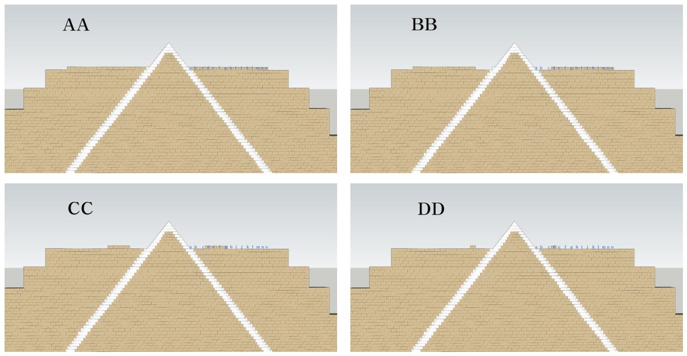
The tiers come away from the top down, course by course (Figure 10). At each course the strip of blocks against the face is removed first, and the face behind it is dressed while the outer blocks are taken away. Dressing and removal therefore run side by side, and the finishing lasts as long as the longer of the two, not their sum. The ramps are needed to the top, so the dismantling begins only after the last course and the pyramidion are set.
The face to dress is 85,900 m². No measured rate exists for dressing Tura limestone with copper tools and hard stones. A nineteenth-century rate for rough dressing with iron tools, 2.4 to 8 hours a square metre (Pegoretti, after Pakkanen 2023), gives 20,600 to 68,700 man-days of 10 hours for the whole face. Crews working one strip behind the removal absorb it, and the dressing does not set the pace. A loaded sledge going down 1:8 at a friction of 0.2 still needs a light pull, but it must also be held; the descending flow is modelled with the capacity of the ascending one.
12. Crews, Sledges, Water and Food
At the theoretical capacity of the design, with expected values, the camp would average about 11,900 men over the lift; a build of 23 to 27 years needs about half of it (Section 13). Quarrymen are counted at 0.10 m3 a man-day (first paper), at the steady rate of 671 m3 of block a day. The support roll follows the first paper: one overseer in ten, five smiths per hundred quarrymen, three carpenters per hundred haulers, and five bakers and brewers per hundred men.
| H]ll Line | Men, mean over the lift |
| Quarrymen | 6,706 |
| Haulers, quarry to the foot of the ramps (400 m) | 1,501 |
| Haulers on the ramps | 1,021 |
| Deck crews | 246 |
| Setters and casing fitters | 467 |
| Overseers, smiths, carpenters | 1,412 |
| Bakers and brewers | 597 |
| Camp | 11,949 |
On site, the haulers, deck crews and setters peak at about 7,100 on the first course, where four ramps feed the course. About 160 sledges are in use at once.
The track is wetted to lower the friction. On an evaporation basis (FAO-56, Allen et al. 1998; 3 to 7 mm a day at Giza) the ramps and the approach lose 11 to 25 m3 of water a day; water lost into the joints is not counted (Section 16). The men drink about 54 m3 a day at 4.5 L a man (Howard and Bartram 2003). Bread and beer at ten loaves and a jug a man (first paper) come to about 119,000 loaves a day.
Water and provisions for the men on the tiers go up separately from the sledges: carried on the back by the stairs for a few hours after sunset and stored in jars on the terraces. Latrine jars go down with the men; this last point is an assumption without direct evidence.
13. Reign and Camp
The work is the preparation of the site, the lift and the finishing, at 328.5 working days a year. With every unmeasured value at its worst (Section 14), the lift takes 22.1 years. With the finishing (1.3 years) and one year of preparation, the work comes to 24.5 years, within the 27 years attested by the Diary of Merer. With expected values the capacity of the construction is 12.0 years of lift, a theoretical figure that gives a scale, not an estimate of the build. A longer reign spreads the same work, about 47 million man-days, over more days. It needs a slower quarry and a smaller camp.
| H]llll Build | Lift (years) | Quarry rate (m3 of block a day) | Camp, mean (men) |
| 27 years | 24.7 | 326 | 5,800 |
| 23 years (Turin Canon) | 20.7 | 389 | 6,900 |
| 20 years | 17.7 | 455 | 8,100 |
| Theoretical capacity, expected values | 12.0 | 671 | 11,900 |
Each build includes one year of preparation and 1.3 years of finishing. Quarry rates include the tier stone, 2.64 million m3 in all. At the 283 m3 a day of the first paper the lift alone would take 28.4 years: the documented reign requires a faster quarry, which the parallel fields of the plateau allow (Section 7). The camp of a slower build is the same work spread over more days.
The Diary of Merer shows Tura limestone still arriving in the year after the thirteenth cattle count, year 26 or 27 of Khufu, most probably but not only for the casing, at the final stage of the work (Tallet 2017; Tallet and Marouard 2014). In this design the casing rises with the courses, and the dismantling begins once the pyramidion is set. Unless these blocks went to other works of the complex, the last courses were therefore laid near the end of the reign: the build filled the reign, as in the worst case, and the capacity of 12.0 years was not used in full. The camp of a build of 27 years then applies, about 5,800 men. The diary does not date the start of the work.
Stone budget. The pyramid needs 2.37 million m3 of block above the bedrock and the tiers 0.27 million m3. The main quarry yielded about 2.76 million m3 gross (AERA, after Lehner), with a waste that may reach 30 per cent. The budget closes only with other quarry fields on the plateau, or with the tier stone reused from earlier works; the volumes of those fields remain to be measured.
14. Sensitivity
Five values of the model have never been measured: the time a turn takes, the loading time at the foot, the time to set a core block, the time to set out a course, and the time to turn a granite beam on a terrace. The pull of a man and the friction of the track are also uncertain; the speed of a loaded sledge follows from the pull and the 75 W a man sustains. The table gives the lift with each value moved alone, the base case otherwise (12.0 years, the theoretical capacity with expected values).
| H]llll Value | Setting | Lift (years) | Sets the pace |
| Base case | turn 0.5 min, loading 2 min, core block 30 crew-min, setting out 1 day, 300 N at 0.195 m/s, friction 0.2 | 12.0 | ramps 90 %, core setting 7 % |
| Core setting | 10 crew-min | 11.9 | ramps |
| Core setting | 60 crew-min | 16.9 | core setting |
| Core setting | 60 crew-min, four laying fronts | 12.0 | ramps |
| Core setting | 120 crew-min | 33.1 | core setting |
| Laying fronts | one | 17.2 | core setting |
| Setting out | half a day | 11.7 | ramps |
| Setting out | 3 days | 13.3 | ramps |
| Setting out | 3 days, blocks stockpiled meanwhile | 12.2 | ramps |
| Casing | 30 crew-min a block | 11.9 | ramps |
| Turn | 2 min | 18.6 | ramps |
| Turn | 3 min | 24.2 | ramps |
| Loading | 3 min | 17.1 | ramps |
| Loading | 4 min | 22.5 | ramps |
| Pull per man | 250 N at 0.22 m/s | 11.9 | ramps |
| Pull per man | 350 N at 0.17 m/s | 12.1 | ramps |
| Friction | 0.3 | 12.3 | ramps |
| Sledge speed | 0.15 m/s (Rosell Roig 2026) | 12.8 | ramps |
| Sledge speed | 0.4 m/s, above the power of a man | 11.7 | ramps |
| End of the day | loaded sledges chocked on the ramp overnight | 11.4 | ramps |
| Granite beams | 80 t, 90 min to turn each beam on a terrace | 12.3 | ramps |
| East ramp | one lane | 15.3 | ramps |
| Empty sledges | one at a time down the chute | 14.8 | ramps |
| Rubble ramps | none | 12.8 | ramps |
| Rubble ramps | two, to 30.2 m | 11.1 | ramps |
| Bedrock | two steps only, to 6 m | 12.1 | ramps |
| Bedrock | a rock pyramid 7 m high (first paper) | 12.3 | ramps |
| All unfavourable | core 60 crew-min, setting out 3 days, turn 2 min, loading 3 min, 350 N, friction 0.3 | 22.1 | ramps 78 %, core setting 21 % |
The turn and the loading matter most: because the ramps set the pace, each extra minute at either lengthens the lift by five to six years. A core block that takes an hour to set needs four laying fronts to keep up; at two hours the setting sets the pace and the lift takes 33 years. With all values unfavourable the lift takes 22.1 years, and the whole work, with preparation and finishing, 24.5 years; with the granite also at its worst (80 t beams, 90 minutes to turn each beam on a terrace), 22.4 and 24.7 years. The lift reaches the limit left by the reign, 24.7 years, when a core block takes 89 crew-minutes to set, or 81 with every other value at its worst; with four laying fronts the limit is 179 crew-minutes. The speed of the sledge matters little: at 0.15 m/s the lift takes 12.8 years. A continuous turn round a stone post, with the crew already on the next leg, is estimated at about 30 s; a turn in which the rope is untied and retied would take 2 to 3 minutes. The measurements that would most strengthen or refute the result are the time of a turn round a post with a loaded sledge and the time to set a core block.
15. Evidence and Tests
The design predicts traces that can be looked for, and each could refute it. The removal of the casing between the twelfth and sixteenth centuries damaged the faces and the base (Monnier 2022) and may have erased some of them.
| H]llll Prediction | Where to look | Refuted if | Looked for |
| Bedding or cuttings of the tier walls on the rock or pavement round the base | the four sides of the base; the east court | the rock and pavement carry no trace along the base lines | not yet |
| Tool marks on the lowest casing that differ from those of the upper courses | the casing surviving at the base (Petrie 1883) | the same tooling from base to top | not yet |
| Blocks with the size and dressing of the tiers reused in the queens’ pyramids and the mastabas | cores of G1-a to G1-c and of the mastabas | no block of that size and dressing | not yet |
| Work-gang marks in red ochre on reused tier blocks | inner faces of reused blocks | none where marks would survive | not yet |
| Stone posts of the turns, with deep rope grooves, reused in later works | reused blocks on the plateau | no grooved post | not yet |
| No large ramp dump at Giza | the plateau | a dump of block the size of the tiers | yes: none found (Klemm and Klemm 2010; Müller-Römer 2011) |
| Chip, gypsum and tafla deposits from haul roads, not from the tiers | the main quarry (Lehner 1985) | the deposits hold dressed block | partly |
Three further observations are consistent with the design but do not test it: the ramp of chips, gypsum and tafla south-west of the pyramid (Hawass 1998), the post holes beside the Hatnub ramp (Gourdon and Enmarch 2018), and the hauling scene of Djehutihotep, with water poured before the sledge. No published survey reports wear, mortar lines or debris from a structure against the faces on the surviving platform and pavement (Petrie 1883; Dash and Paulson 2016). In the sequence of Section 3 the tiers stand beyond the platform ledge, 30 to 45 cm wide (Maragioglio and Rinaldi 1965, 12), and the court pavement is laid after the lowest tier comes down, so no wear is expected there. The masons’ chip banks, thrown over the cliffs north and south of the pyramid, probably hold more than half its bulk (Petrie 1883, §170); the 7,700 m3 of the rubble ramps is a small part of such dumps, and the ramp of chips, gypsum and tafla south-west of the pyramid (Hawass 1998) is of the same kind.
15.1. Missing Information and How to Obtain It
The information below is not measured or not yet checked, and each item could change the result. The items are listed in order of their effect. The worst cases are those of Section 14.
| H]lll Information | Effect on the result | How to obtain it |
| Time to turn a loaded sledge round a post | lift of 18.6 years at 2 min and 24.2 at 3 min (30 s in the base case) | a field trial: a 2.5 t sledge on a wetted 1:8 track of chips and tafla, a stone post and a crew of the model |
| Loading time at the foot of a ramp | lift of 17.1 years at 3 min and 22.5 at 4 min (2 min in the base case) | the same trial |
| Time to set a core block | lift of 16.9 years at 60 crew-min and 33.1 at 120 (30 in the base case) | joint widths, chip packing and mortar on the core courses exposed where the casing and backing are gone; a setting trial with levers and packing |
| Material of the tiers | the stone cost of the tiers and their reuse | traces round the base; blocks of tier size and grooved posts of the turns in works begun after the tiers came down |
| Traces of the tiers | a direct test of the design | a survey of the rock and pavement along the base lines and in the east court; the tooling of the lowest casing |
| Extent of the bedrock under the pyramid | lift of 12.3 years with a 7 m knoll; the stone budget | levels of the rock in the descending passage, the grotto and the corner sockets, with a surface fitted through them; a non-invasive survey of the base |
| Beams of the relieving chambers | lift of 12.3 years with 80 t beams | the dimensions of each beam, measured in the chambers |
| Dates of the court, the upper temple and the queens’ pyramids relative to the removal of the tiers | the site plan and the reuse of the tier blocks | the joints and foundations where the temple and the court meet the platform (Maragioglio and Rinaldi 1965); the dating of G1-a to G1-c (Reisner 1942) |
| Size of the workforce | the camp of 5,800 to 6,900 men for a build of 27 to 23 years | the capacity of the galleries and bakeries of the workers’ town at Heit el-Ghurab (Lehner and Wetterstrom 2007) |
16. Assumptions and Limits
The following are stated and not modelled.
- Stone at the foot. The stone of the pyramid and the tiers waits at the foot of the ramps. Several quarry fields were worked side by side; their volumes are not known, and the quarry rate is an output of the reign.
- Unmeasured values. Turn time, loading time, setting time, setting out, the turn of a beam, pull per man and friction are taken from the literature or assumed, and tested in Section 14; none has been measured on a site of this kind.
- Granite. The counts are measured: 9, 9, 9, 9 and 8 beams in the five granite ceilings (Maragioglio and Rinaldi 1965). The masses are not: about 400 t for the nine beams of the King’s Chamber (Petrie 1883) and an average of about 54 t for the others (Petrie 1883, §169); Houdin gives 43 beams of about 2,100 t. The strength of the ropes is not modelled; an 80 t beam puts about 28 kN on each of nine ropes.
- Two lanes on the wide ramp. Each lane is taken to have its own loading point and its own post at each turn.
- Removal and dressing rates. Removal is taken at 3.8 m3 a man-day. The dressing rate is a nineteenth-century rate with iron tools; the finishing assumes the dressing does not set the pace.
- Camp. Quarrymen at 0.10 m3 a man-day and the support roll follow the first paper. The camp of a slower build is the same work spread over more days.
- Site preparation. One year, as a parameter.
- Track water. Water lost into the joints of a dry-laid ramp is not counted; the figures are for evaporation only.
- Details that do not change the numbers. Rails, kerbs and the open edge of the ramps.
- Sources. One figure rests on a secondary work: the quarry volume (Lehner 1985, through AERA). The Diary of Merer gives a floor for the reign, not its length.
The values of the model and their basis are listed below. A value is measured where a survey or an experiment gives it, and assumed otherwise; every assumed value has an expected case, our best reasoning, and a worst case tested in Section 14.
| H]lll Value | Base case | Basis |
| Base and height | 230.3 m, 146.6 m | measured (Petrie 1883) |
| Course heights | 217 courses | measured (Petrie 1883) |
| Bedrock under the pyramid | three steps of 3 m, 180, 160 and 140 m wide | shape and height measured (Maragioglio and Rinaldi 1965; Lehner and Hawass 2017); widths assumed (Choi 2021) |
| King’s Chamber floor and ceiling | 43.0 m, 48.8 m | measured (Petrie 1883) |
| King’s Chamber ceiling beams | nine, about 400 t together | measured (Petrie 1883) |
| Beams of the relieving chambers | 35 of 54 t; 44 with the King’s Chamber, about 2,290 t | counts measured (Maragioglio and Rinaldi 1965); mean mass from Petrie’s dimensions (Petrie 1883, §169) |
| Ramp grade | 1:8 | within the attested range, 1:12 to 1:5 (Dunham 1956; West, Gallagher and Waters 2014; Gourdon and Enmarch 2018) |
| Friction of the wetted track | 0.2 | within the published range, 0.07 to 0.37 (Chevrier 1970; Fall et al. 2014) |
| Pull of a man | 300 N | measured on modern workers (Snook and Ciriello 1991) |
| Power of a man over a day | 75 W | measured on modern workers (West, Gallagher and Waters 2014) |
| Speed of a loaded sledge on the ramp | 0.195 m/s | derived from the pull and the power |
| Loading at the foot | 2 min | assumed |
| Turn round a post | 30 s | assumed |
| Working day | 10 hours | first paper |
| Setting a core block | 30 crew-min | assumed, between the lever experiments (Hussey-Pailos 2005; Isler 2001) |
| Fitting a casing block | 6 crew-hours | assumed (first paper) |
| Setting out a course | 1 day | assumed |
| Quarrying | 0.10 m3 a man-day | within the published range, 0.02 to 0.25 (first paper) |
| Bread and beer | ten loaves and a jug a man | first paper |
| Drinking water | 4.5 L a man | standard for heavy work in heat (Howard and Bartram 2003) |
| Track water | 3 to 7 mm a day | measured evaporation (Allen et al. 1998) |
| Removal of the tiers | 3.8 m3 a man-day | assumed (first paper) |
| Dressing the face | 2.4 to 8 hours a m² | nineteenth-century rate (Pakkanen 2023) |
17. Conclusion
A complete construction design for the Great Pyramid can be built course by course with the stone waiting at the foot. Each course is finished with its casing, and thirty-five dry-laid tiers ring the four faces. Two back-and-forth ramps at 1:8 carry the blocks. The east one is wide enough below 65.9 m for the granite beams and for two lanes of sledges, and two short rubble ramps help on the lowest courses. With every unmeasured value at its worst, the lift takes 22.1 years and the whole work 24.5, within the 27 years attested for the reign. With expected values the capacity is 12.0 years of lift, a theoretical figure that gives a scale, not an estimate of the build. The ramps set the pace on most days, and the setting of the core near the top. The tiers cost 10.4 per cent of the pyramid in reusable block and leave no ramp dump.
The work is about 47 million man-days. The reign sets the size of the camp, not whether the work can be done: about 5,800 men on average for a build of 27 years and 6,900 for 23 years. Even at the theoretical capacity of the design the site would need no more than about 160 sledges, 65 to 79 m3 of water and some 119,000 loaves a day. The result rests most on the time of a turn and of a loading at the ramps, and on the time to set a block. It would be refuted if the turn, the loading and the setting, measured on site, took the lift beyond 24.7 years, the time the reign leaves after the preparation and the finishing, or by the absence of any trace of the tiers at the foot of the faces and in the reused blocks of the queens’ pyramids.
18. Glossary
| H]ll Term | Meaning |
| Course | One horizontal layer of blocks of the pyramid. |
| Core | The inner masonry of the pyramid, inside the backing and the casing. |
| Backing | The blocks between the core and the casing. |
| Casing | The outer blocks of fine limestone, dressed at the end. |
| Tier | An external step of dry-laid block against a face, one or more courses high, with a vertical outer wall; a mastaba in the reconstruction (Choi 2021). |
| Terrace | The flat top of a tier, the working floor beyond the face. |
| Leg | One straight run of a ramp, climbing one tier. |
| Turn | The change of direction between two legs, round a fixed stone post. |
| Lane | A file of sledges on a ramp, one behind the other. |
| Gate | A place on the route that only one sledge passes at a time: the loading point, a turn. |
| Load | One sledge with its block. |
| Rubble ramp | A short ramp of rubble serving the lowest courses, cleared afterwards. |
| Deck | The top of the course below, on which the blocks of the next course are hauled and set. |
| Laying front | The edge of the laid part of a course, along which setting crews work, one every 6 m. |
| Setting out | Levelling the top of a course and marking the axes and the edge of the next. |
| Quarry rate | Block delivered by the quarries, in m3 a working day; here an output of the reign. |
| Chute | A timber slide on which the empty sledges are lowered on brake ropes, in trains of three. |
| Finishing | The dismantling of the tiers and ramps with the dressing of the face. |
| Pyramidion | The capstone of the pyramid. |
| Route model | The minute-by-minute simulation of the ramps. |
| Course model | The simulation of each course: setting out, ramps, deck, setting and granite. |
Author Contributions
J.-H. Choi made the reconstruction (tiers, ramps, construction sequence and finishing), first drawn in 2014 and published in Choi (2021), and all the drawings. J.-J. Dubray built the route and course models. Both authors wrote the paper.
Acknowledgments
We thank Franck Monnier for his remarks on the quarries of the plateau.
Appendix A. Chronology of the construction
The six drawings below follow the reconstruction (Choi 2021) from the first courses to the end of the finishing. They show the sequence of Section 3 to 11: the courses laid round the bedrock knoll, the tiers and ramps rising with the courses, then the tiers taken down from the top while the face is dressed. Drawings: Choi.
Figure A1.
The first courses laid round the bedrock knoll; the lower step of the knoll is 180 m wide.
Figure A1.
The first courses laid round the bedrock knoll; the lower step of the knoll is 180 m wide.
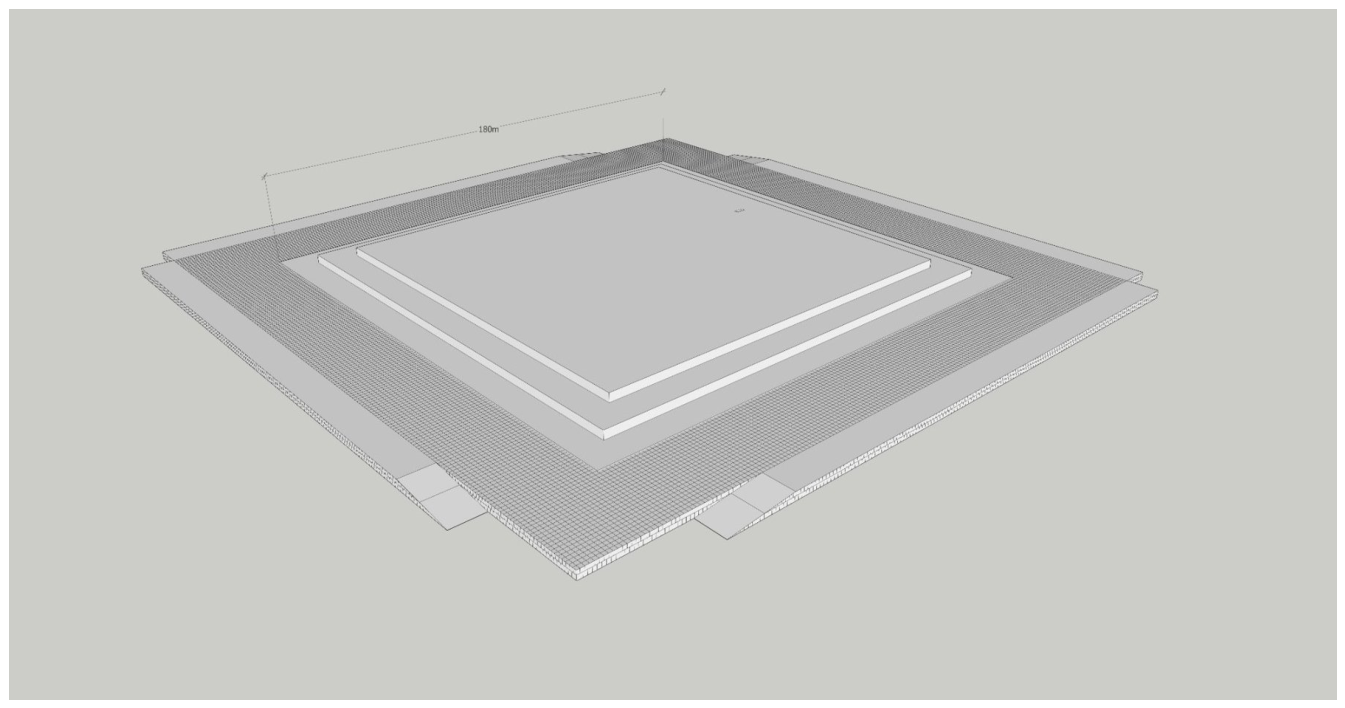
Figure A2.
The courses close over the knoll; the first tier and the first ramp legs stand against the faces.
Figure A2.
The courses close over the knoll; the first tier and the first ramp legs stand against the faces.
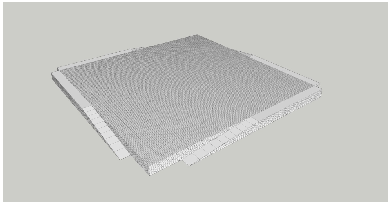
Figure A3.
Crews haul the sledges up the back-and-forth ramps of the tiers.
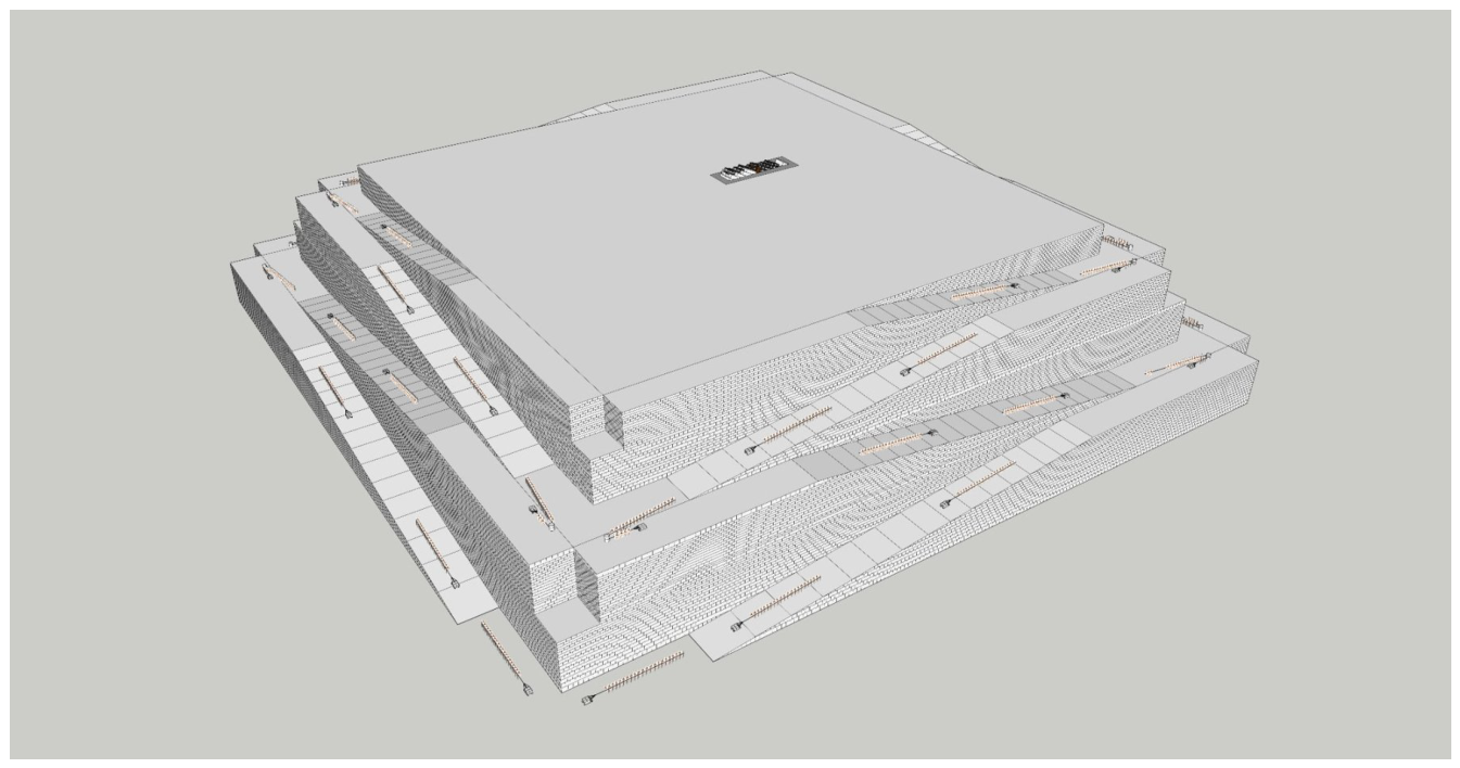
Figure A4.
The tiers and ramps near the top of the pyramid.
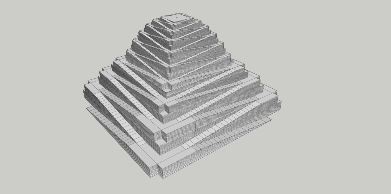
Figure A5.
After the pyramidion is set, the tiers come away from the top and the face behind them is dressed.
Figure A5.
After the pyramidion is set, the tiers come away from the top and the face behind them is dressed.
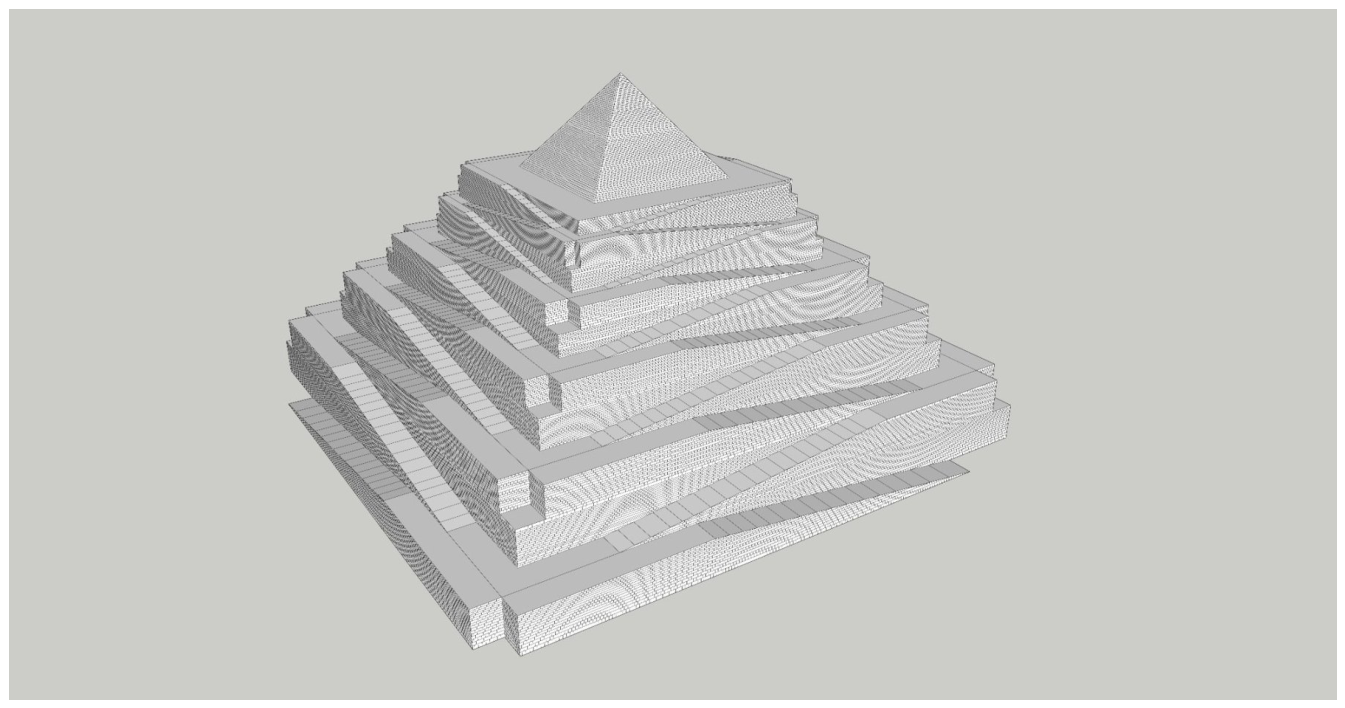
Figure A6.
The end of the finishing: only the lowest tiers remain round the dressed pyramid.
References
- ERA. The Great Pyramid Quarry. Ancient Egypt Research Associates Available online: aeraweb.org/great-pyramid-quarry.
- Allen, R. G.; Pereira, L. S.; Raes, D.; Smith, M. Crop evapotranspiration. In FAO Irrigation and Drainage Paper; FAO: Rome, 1998; p. 56. [Google Scholar]
- Arnold, D. Building in Egypt: Pharaonic Stone Masonry; Oxford University Press, 1991. [Google Scholar]
- Brichieri-Colombi, S. The ramp at Hatnub quarry: no solution for pyramids. PalArch’s Journal of Archaeology of Egypt/Egyptology 2019, 16(1), 1–21. [Google Scholar]
- Chartier, M. La pyramide de Khéops et ses « chambres de décharge », ou les conséquences techniques de la construction d’un plafond plat pour la Chambre du Roi, selon Jean-Pierre Houdin. Pyramidales. 2011. Available online: pyramidales.blogspot.com.
- Chevrier, H. Technique de la construction dans l’ancienne Égypte. II. Problèmes posés par les obélisques. Revue d’Égyptologie 1970, 22, 15–39. [Google Scholar]
- Choi, J.-H. Understanding Pyramid Construction Through Illustrations; Sacheon Publishing: Sacheon, 2021; ISBN 979-11-97477-81-2. (in Korean) [Google Scholar]
- Cognitive Fab 2026. Available online: Polytrion..
- Dash, G.; Paulson, J. The 2015 survey of the base of the Great Pyramid. Journal of Egyptian Archaeology 2016, 102, 186–196. [Google Scholar] [CrossRef]
- Delvaux, S. L’enseignement de la documentation iconographique de l’Ancien et du Moyen Empire quant à l’utilisation du traîneau. The Journal of Ancient Egyptian Architecture 2018, 3, 45–63. [Google Scholar]
- Dreyer, G.; Swelim, N. Die kleine Stufenpyramide von Abydos-Süd (Sinki). Grabungsbericht. MDAIK 1982, 38, 83–93. [Google Scholar]
- Dubray, J.-J.; Choi, J.-H. A critical review of the logistics and construction methods for the Great Pyramid using a discrete-event digital twin. Preprint 2026. [Google Scholar] [CrossRef]
- Dunham, D. Building an Egyptian pyramid. Archaeology 1956, 9(3). [Google Scholar]
- El Awady, T. Abusir XVI. Sahure, the pyramid causeway: history and decoration program in the Old Kingdom; Charles University: Prague, 2009. [Google Scholar]
- Fall, A.; Weber, B.; Pakpour, M.; Lenoir, N.; Shahidzadeh, N.; Fiscina, J.; Wagner, C.; Bonn, D. Sliding friction on wet and dry sand. Physical Review Letters 2014, 112, 175502. [Google Scholar] [CrossRef]
- Farout, D. La carrière du wHmw Ameny et l’organisation des expéditions au Ouadi Hammamat au Moyen Empire. BIFAO 1994, 94, 143–172. [Google Scholar]
- Gourdon, Y.; Enmarch, R. Ancient quarry ramp system may have helped workers build Egypt’s Great Pyramids. University of Liverpool news release, 2018. Available online: news.liverpool.ac.uk.
- Goyon, G. Le secret des bâtisseurs des grandes pyramides: Khéops; Pygmalion: Paris, 1977. [Google Scholar]
- Hawass, Z. The discovery of the satellite pyramid of Khufu (GI-d). In Studies in Honor of William Kelly Simpson; Der Manuelian, P., Ed.; Museum of Fine Arts: Boston, 1996; Volume 1, pp. 379–398. [Google Scholar]
- Hawass, Z. The discovery of the pyramidion of the satellite pyramid of Khufu (GI-d). In Iubilate Conlegae: Studies in Memory of Abdel Aziz Sadek, part 1. Varia Aegyptiaca; Van Siclen III, C. C., Ed.; 1997; Volume 10, 2-3, pp. 105–124. [Google Scholar]
- Hawass, Z. Pyramid construction: new evidence discovered at Giza. In Stationen. Beiträge zur Kulturgeschichte Ägyptens Rainer Stadelmann gewidmet.; Guksch, H., Polz, D., Eds.; von Zabern: Mainz, 1998; pp. 53–62. [Google Scholar]
- Houdin, J.-P. Khufu: The Secrets Behind the Building of the Great Pyramid; Farid Atiya Press: Cairo, 2006. [Google Scholar]
- Howard, G.; Bartram, J. Domestic Water Quantity, Service Level and Health; World Health Organization: Geneva, 2003. [Google Scholar]
- Hussey-Pailos, R. S. Construction of the top of the Egyptian pyramids: an experimental test of a levering device. MA thesis, University of Florida, 2005. [Google Scholar]
- Isler, M. Sticks, Stones, and Shadows: Building the Egyptian Pyramids; University of Oklahoma Press: Norman, 2001. [Google Scholar]
- Klemm, D.; Klemm, R. The Stones of the Pyramids; de Gruyter: Berlin, 2010. [Google Scholar]
- Lauer, J.-P. Le mystère des pyramides; Presses de la Cité: Paris, 1960. [Google Scholar]
- Lehner, M. Some observations on the layout of the Khufu and Khafre pyramids. JARCE 1983, 20, 7–25. [Google Scholar] [CrossRef]
- Lehner, M. The development of the Giza necropolis: the Khufu project. MDAIK 1985, 41, 109–143. [Google Scholar]
- Lehner, M. The Complete Pyramids; Thames and Hudson: London, 1997. [Google Scholar]
- Lehner, M.; Hawass, Z. Giza and the Pyramids; Thames and Hudson: London, 2017. [Google Scholar]
- Lehner, M.; Wetterstrom, W. (Eds.) Giza Reports: The Giza Plateau Mapping Project; Ancient Egypt Research Associates: Boston, 2007; Volume 1. [Google Scholar]
- Maragioglio, V.; Rinaldi, C. L’Architettura delle Piramidi Menfite, parte IV: La piramide di Cheope. In Testo e tavole; Canessa: Rapallo, 1965. [Google Scholar]
- Monnier, F. L’ère des géants. Une description détaillée des grandes pyramides d’Égypte; De Boccard: Paris, 2017. [Google Scholar]
- Monnier, F. Données nouvelles sur les appareils de maçonnerie des grandes pyramides. ENiM 2020a, 13, 237–261. [Google Scholar]
- Monnier, F. La scène de traction du colosse de Djéhoutyhotep. Description, traduction et reconstitution. The Journal of Ancient Egyptian Architecture 2020b, 4, 55–72. [Google Scholar]
- Monnier, F. The so-called concave faces of the Great Pyramid: facts and cognitive bias. Interdisciplinary Egyptology 2022, 1(1), 1–18. [Google Scholar] [CrossRef]
- Monnier, F.; Puchkov, A. The construction phases of the Bent Pyramid at Dahshur. A reassessment. ENiM 2016, 9, 15–36. [Google Scholar]
- Müller-Römer, F. A new consideration of the construction methods of the ancient Egyptian pyramids. JARCE 2008, 44, 113–140. [Google Scholar]
- Müller-Römer, F. Der Bau der Pyramiden im Alten Ägypten; Utz: Munich, 2011. [Google Scholar]
- Pakkanen, J. Building accounts, monumental construction projects and labour rates in the Classical and Hellenistic periods. In From Concept to Monument: Time and Cost of Construction in the Ancient World; Barker, S., Courault, C., Domingo, J. Á., Maschek, D., Eds.; Archaeopress: Oxford, 2023; pp. 266–285. [Google Scholar]
- Petrie, W. M. F. The Pyramids and Temples of Gizeh; Field and Tuer: London, 1883. [Google Scholar]
- Reisner, G. A. A History of the Giza Necropolis, vol. I; Harvard University Press: Cambridge, MA, 1942. [Google Scholar]
- Rosell Roig, V. L. A computational framework for evaluating an edge-integrated, multi-ramp construction model of the Great Pyramid of Giza. npj Heritage Science 2026, 14, 142. [Google Scholar] [CrossRef]
- Snook, S. H.; Ciriello, V. M. The design of manual handling tasks: revised tables of maximum acceptable weights and forces. Ergonomics 1991, 34(9), 1197–1213. [Google Scholar] [CrossRef]
- Tallet, P. Les papyrus de la mer Rouge I: le journal de Merer. In MIFAO 136; IFAO: Cairo, 2017. [Google Scholar]
- Tallet, P.; Marouard, G. The harbor of Khufu on the Red Sea coast at Wadi al-Jarf, Egypt. Near Eastern Archaeology 2014, 77(1), 4–14. [Google Scholar] [CrossRef]
- Veldmeijer, A. J.; Zazzaro, C. The `Rope Cave’ at Mersa/Wadi Gawasis. JARCE 2008, 44, 9–39. [Google Scholar]
- West, J.; Gallagher, G.; Waters, K. How they (should have) built the pyramids. arXiv 2014, arXiv:1408.3603. [Google Scholar]
Figure 3.
Section through one face: two external tiers, the terrace and a ramp.
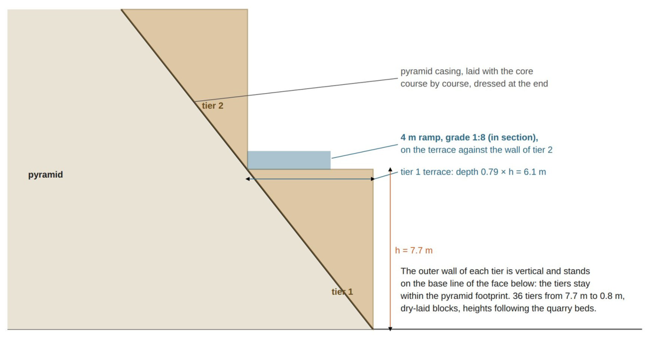
Figure 9.
Setting the pyramidion, four views: the sledge hauled round the stone post on the top terrace; drawn towards the paved last course; on the last course beside its socket; in place.
Figure 9.
Setting the pyramidion, four views: the sledge hauled round the stone post on the top terrace; drawn towards the paved last course; on the last course beside its socket; in place.
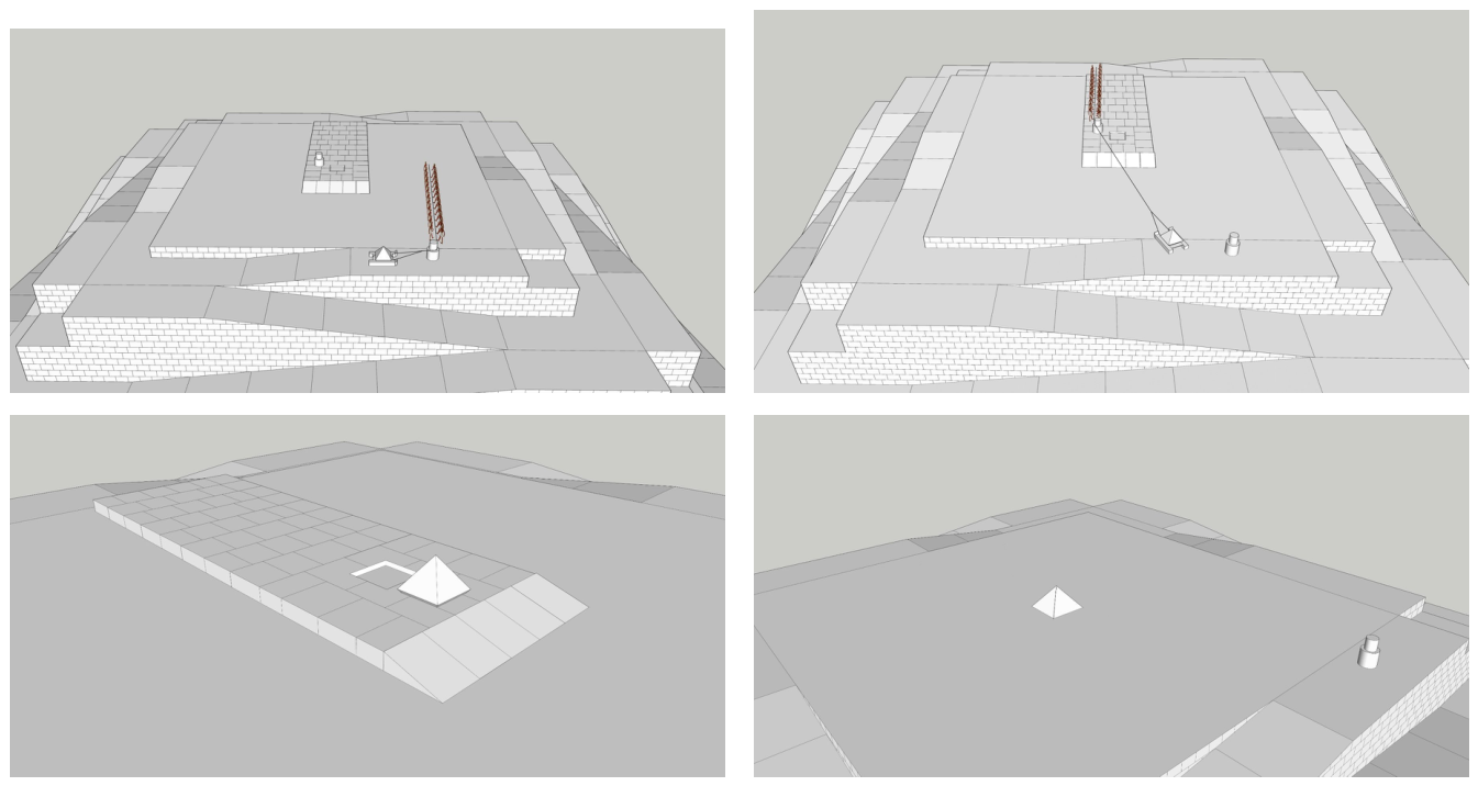
Figure 10.
The dismantling order, four stages (AA to DD): the tiers come away from the top while the face behind them is dressed.
Figure 10.
The dismantling order, four stages (AA to DD): the tiers come away from the top while the face behind them is dressed.
Disclaimer/Publisher’s Note: The statements, opinions and data contained in all publications are solely those of the individual author(s) and contributor(s) and not of MDPI and/or the editor(s). MDPI and/or the editor(s) disclaim responsibility for any injury to people or property resulting from any ideas, methods, instructions or products referred to in the content. |
© 2026 by the authors. Licensee MDPI, Basel, Switzerland. This article is an open access article distributed under the terms and conditions of the Creative Commons Attribution (CC BY) license.
Copyright: This open access article is published under a Creative Commons CC BY 4.0 license, which permit the free download, distribution, and reuse, provided that the author and preprint are cited in any reuse.