
Submitted:
06 October 2026
Posted:
09 October 2026
You are already at the latest version
Abstract
Underwater multistatic sonar cooperative detection faces the issue that distant sonars fail to capture target echoes. This paper proposes a networkcodingaided multistatic multicast system with relaysonar assistance for underwater acoustic networks. Relay sonars forward activesonardetected target data to remote sonars and apply network coding prior to forwarding to cut retransmissions and boost transmission efficiency. To mitigate latency in traditional opportunisticlisteningbased network coding, a feedbackdriven proactive coding scheme is adopted: remote sonars feed back receivedpacket indexes, enabling relays to proactively encode complementary missing packets. A throughput analytical model is built to derive closedform expressions under maximum encodingnumber constraints for arbitrary remotesonar quantities. Simulations reveal prominent networkcoding gains at moderate packetloss rates. In highloss scenarios, the scheme improves throughput efficiency by 30%60%, outperforming schemes without network coding or relays and supporting reliable, bandwidthsaving underwater acoustic transmission.
Keywords:
underwater multicast system
; multistatic sonar
; network coding
1. Introduction
Sonar detection of underwater targets (e.g., large aquatic creatures or underwater vehicles) usually relies on receiving echoes reflected from targets. When sonars are far away from targets, target echoes cannot be correctly captured. In this work, relay sonars forward target information (echo signals) captured by active sonars to geographically distributed remote sonars. Relay sonars process received information with network coding before forwarding, constructing an underwater multistatic sonar multicast system. The proposed system improves transmission reliability, covertness, and cooperative detection performance under complex underwater conditions.
Network coding theory originated from the max flow min cut theorem proposed by Elias et al. in 1956 [1]. Traditional store and forward routing cannot achieve this theoretical upper bound. In 2000, Ahlswede et al. proposed network coding: intermediate network nodes encode incoming information flows before forwarding data. Network coding improves network throughput and robustness and reduces energy consumption, yet introduces extra computational overhead and end to end delay; hence comprehensive trade offs are required.
Network coding enables intermediate nodes to execute both routing and coding functions. Nodes combine different incoming packets by XOR operations to approach multicast capacity derived from the max flow min cut theorem [1]. When one node transmits packets to a neighbor, other overhearing neighbors may also capture these packets. If different neighbors lose different packets, intermediate nodes can generate one single encoded XOR packet for multiple destinations, saving transmission energy.
Network coding research has been extended to underwater acoustic networks. The broadcast nature and complex time varying channels of underwater acoustic networks make network coding highly applicable. It improves multicast throughput, cuts transmission times and energy consumption, and enhances fault tolerance under node or link failures. Nevertheless, few studies focus on specialized coding optimization algorithms for practical underwater acoustic transmission. Network coding can be classified as linear/non linear network coding; according to coefficient generation rules, it can also be divided into random network coding and deterministic network coding.
Dynamic random nonlinear network coding combined with cross layer optimization represents the mainstream research direction for underwater acoustic networks. Early fundamental research includes: Lucani et al. derived transmission power lower bounds for network coded multicast [2]; Chitre and Soh verified that mixed coding outperforms classic retransmission and erasure coding schemes [3]; Mo et al. proposed an opportunistic listening based two phase broadcast protocol [4]; Kebkal et al. validated coding gains over commercial underwater acoustic modems using butterfly topologies [5]. Later work includes field tests by Sucasas et al., which revealed severe performance degradation of random linear network coding under time varying packet loss [6]; Gao et al. proposed reinforcement learning driven sparse parameter online adjustment [7]. Physical layer coding, fountain code variants and source location privacy protection based on network coding were further investigated in follow up publications [8,9,10]. Very recent studies indicate that reinforcement learning assisted adaptive network coding and cross layer joint optimization become core approaches to boost underwater multicast reliability and throughput [11,12,13,14]. These existing results motivate our research on relay sonar assisted multicast for multistatic sonar scenarios.
2. Materials and Methods
This article presents a hybrid scheme combining the advantages of network coding with feedback-driven proactive coding. We first investigate a four-sonar scenario containing one active sonar, one cooperative relay sonar, and two remote sonars ,and then further generalize this architecture to a multi-relay multicast system consisting of one active sonar, multiple relay sonars and multiple remote sonars .
After receiving data packets, destination sonars feed back indexes of the packets that they had received to relay sonars. Instead of waiting for passive overhearing opportunities, relay sonars actively encode complementary missing packets of the remote sonars according to feedback reports and broadcast encoded packets in one transmission. This approach retains network-coding gains (reduced retransmissions, higher throughput) and eliminates latency overhead introduced by opportunistic listening. It matches long-delay and intermittently-connected underwater acoustic channels and constitutes the key difference compared with existing opportunity -based network-coding solutions.
3. Results
This paper proposes a relay-sonar-assisted multistatic multicast scheme for underwater acoustic networks. Relay sonars located at appropriate geographical positions cooperatively forward source packets originated from active sonars. Network coding operated on relay nodes reduces total retransmission times and improves channel-utilization efficiency and system throughput. Simulation results show that network-coding gains reach maximum under moderate packet-loss conditions .For high-loss underwater acoustic channels, the joint utilization of relay-sonar forwarding and network coding improves throughput efficiency. The proposed solution provides efficient and reliable information delivery for multistatic sonar cooperative-detection scenarios under complex underwater environments .
3.1. Network-Coding Based Single-Relay Multicast System and Multi-Relay Multicast System
3.1.1. A Network-Coding Based Four Sonar Multicast System
Our network-coding-assisted multicast system is inspired by Fan et al. [18]. We first investigate a four-sonar scenario containing one active sonar, one cooperative relay sonar, and two remote sonars, as illustrated in Figure 1.
In this network, when the active sonar is far from remote sonars, the relay sonar located between the source and destinations assists data forwarding [19]. Underwater acoustic channels exhibit time-varying fading, so different remote sonars experience distinct packet-loss performance.
After target detection, the active sonar broadcasts target-related packets over underwater acoustic channels. Remote sonars cannot directly receive all these packets due to long propagation distance; therefore, the relay sonar performs forwarding assistance. Both the active sonar and relay sonar maintain packet-gain index tables fed back from remote destinations. The relay sonar encodes complementary missing packets and forwards encoded combinations. For packets that the relay sonar itself fails to receive, retransmission is performed by the active sonar. Cooperative transmission combined with relay-side network coding reduces total packet transmissions, lowers energy consumption and improves system throughput.
3.1.2. A Network- Coding Based Multi-Relay Multicast System
We further generalize this architecture to a multi-relay multicast system consisting of one active sonar, multiple relay sonars and multiple remote sonars; see Figure 2. Each relay sonar communicates with adjacent relay sonars and transmits data to nearby remote sonars. Each relay maintains received-packet lists according to feedback reports from neighboring remote sonars.
As shown in Figure 2, after receiving packets originated from the active sonar, each relay sonar compares its local packet inventory with adjacent relays and updates its buffer when neighbors possess more valid packets. Afterwards, network-coding operations are executed according to feedback index tables obtained from nearby remote sonars, and encoded packets are broadcasted.
3.2. Multicast Procedure for Relay-Sonar-Assisted Systems
This section described the whole procedure of the Relay-Sonar-Assisted multicast systems.
3.2.1. The Complete Transmission Workflow can be Divided into Four Phases:
1. After the initial transmission time slot, relay sonars check locally-received packets together with received-packet lists obtained from remote-sonar feedback. Once sufficient packets are buffered, new encoded packets are generated via XOR operations.
2. Relay sonars broadcast XOR-combined encoded packets on behalf of the active sonar until all remote sonars successfully decode target data (the active sonar does not participate in this phase).
3. For packets lost both at relay sonars and remote sonars, retransmissions are performed by the active sonar following the same encoding-broadcast procedure described in step 2.
4. Remote sonars perform local decoding over multiple received encoded packets to recover originally-missing source packets.
In Phase 1, the active sonar transmits N consecutive data packets. Active sonar and relay nodes maintain received-packet index tables from remote-sonar feedback. In Phase 2, after N transmission slots, relay sonars execute XOR-based network coding for packets obtaining at remote destinations and broadcast encoded outputs. Different from the four-sonar case, remote sonars receive packets from their corresponding adjacent relays. In Phase 3, packets lost by both relays and remote sonars are retransmitted by the active sonar. In Phase 4, remote destinations recover missing source packets by decoding multiple encoded receptions
3.2.2. Network-Coding Multicast Notation
Denote S as the active-sonar source node; R represents relay sonars; D1, ..., DM stand for M remote receiving sonars; L is total source-packet count. For systems with no more than four receiving nodes, different packet-loss probabilities are assigned for different links. For scenarios with M>3 remote sonars, homogeneous packet-loss probability p is adopted for all links (active-sonar-to-relay and relay-to-remote-sonar). The practical maximum encodable-packet number is typically 2–5. The core principle of network coding exploits packet complementarity among receivers: if Di loses packet x but receives y, and Dj loses packet y but receives x, relay broadcasts x⊕y, and both destinations decode their missing packets.
Illustrative Example of Network-Coding Procedure,We take N=9 source packets to demonstrate the end-to-end network-coding workflow; see Figure 3 and Figure 4.
Packets unreceived by the relay sonar are {2,9}. Packet-loss sets for three remote sonars are {3,7,8,9}, {2,4,6,8}, {3,5,7,9}, respectively. In Phase 1, relay sonar generates encoded combinations: 3⊕4, 5⊕6, 7⊕8, and then forwards these three encoded packets. Remote Sonar 1 or 2 or 3 packets received these packets; for example, upon receiving packet 3⊕4, since it has already received packet 4, 4⊕(3⊕4) = 3, so the received packet 3 is obtained; similarly, received packets 7 and 8 are obtained, thus remote sonars recover missing source packets by local XOR decoding. Since packets 2 and 9 are not captured by the relay, the active-sonar source retransmits encoded packet 2⊕9 in Phase 2. In this example, required transmission times are significantly reduced compared with pure retransmission without network codingsubsection.
3.3. System Throughput Analysis
This section analyzes throughput performance for the relay-sonar-assisted multicast system with network coding. Pij denotes the packet-loss probability over link from node i to node j. We derive average transmission times for one-relay three-receiver multicast systems. Under network coding, buffer size [N] is used for recording received/lost-packet status. Insufficient buffer size reduces coding opportunities; excessively large buffers introduce extra delay, which, however, may benefit file-oriented transmission. In this paper, buffer size is set sufficiently large and equal to the total transmitted-packet count.
3.3.1. Case of Three Remote Destination Sonars
For three remote receiving sonars, let P1, P2, P3 represent respective packet-loss probabilities. Random variables are defined for transmission attempts of combinable and non-combinable packets following geometric distributions. Total transmission-count expression for network-coded multicast with one relay and three receivers is derived, as shown in Equations (1)–(14).
The numbers of received packets corresponding to remote sonars 1, 2, and 3 are NP1, NP2, and NP3,respectively; that is, NP1 < NP2 < NP3 means that only NP1 combined packets can be combined at a time; that is, NP2 − NP1 packets need to be retransmitted at remote sonar 2, and NP3 − NP2 packets need to be retransmitted at Remote Sonar 3. Therefore, for the three receivers to receive a total of [L] packets, the number of transmissions is
where X1 and X2 are random variables representing the numbers of transmission attempts for a successfully transmitted combined packet and a non-combined packet, respectively. E(X3) = 1/(1 − P3),and X2 follow geometric distributions, and we obtain:
n = N + Np₁E[X₁] + N(p₂−p₁)E[X₂] + N(p₃−p₂)E[X₃]
From the random variables :
Therefore,
We can obtain that the number of packets transmitted by the multicast system with one relay sonar and three receivers using network coding is
Let [p1 = p2 = p3 = p]. When network coding is not used, its efficiency is
and when network coding is used,
In the following, an example with one relay sonar and three remote sonars 1 or 2 is used to illustrate that the cooperative transmission through the relay sonar based on network coding has higher throughput than that without network coding. Here psri, psdi, pridi are respectively the probability that a packet is not received from the active sonar to relay sonar i, the probability that a packet is not received from the active sonar to remote sonar i, and the probability that a packet is not received from relay sonar i to remote sonar j. For a unicast system with one relay sonar, its average number of transmissions is (Fan et al., 2008) :
For a system with one relay sonar and three receiving nodes that performs network coding, the average number of transmissions is
where
When psdi = psri = pdi−1 = pdi = pdi+1 = p, a concise form can be obtained:
Expanding the above two equations respectively, we can obtain the bandwidth through the relay sonar with network coding and the efficiency with network coding but without the relay sonar.
When P1 < P2 < P3, throughput efficiencies with- and without-network-coding are obtained. We compare performance against relay-assisted unicast and relay-aided multicast without network coding [18,20].
We further analyze throughput under relay-side and destination-side network coding. Assume the maximum encodable-packet number for both source and relay sonars equals n. Three different reception-status cases are discussed. Conditional mathematical expectation is applied to derive average retransmission times and equivalent bandwidth under given source-packet volume L, see Equations (15)–(17).
In the following, we analyze the throughput when network coding is performed at the relay sonar and the three corresponding destination nodes. In the case where the relay sonar has receivedIpackets, we discuss the case of one active sonar, one relay sonar, and three remote sonars 1 or 2. Here it is assumed that Pi−1 < Pi < Pi+1 are the probabilities of not receiving packets, respectively; therefore, the numbers of PRi−1,PRi and PRi+1 received packets are NPRi−1, NPRi, and NPRi+1,respectively; The relay sonar checks its reception status, combines the packets not received by the destination nodes, and transmits them to the destination nodes. Without considering the sequence numbers, there may be N + 1 cases, that is, from [0] to [N]. If represents the packets correctly received by the L relay sonar in step i, assume that in step i the relay sonar correctly receives K data packets, and the number of packets received by the relay sonar is greater than that received by its destination nodes; there are three cases:
(1) Among the K packets correctly received by the relay sonar i, the number of packets not received by the destination nodes PRi−1 is NPRi−1; received packets are N(1 − Pi−1), the relay sonar PRi−1 retransmits packets K − N(1 − Pi−1), that is, under the condition P(L = K), K − N(1 − Pi−1) more packets need to be retransmitted; when all packets are correctly received, the average total number of transmissions required is .
(2) Among the i packets received by the relay sonar i, the relay sonar PRi have more received packets than the relay sonar PRi−1, In this case, the relay sonar only needs to retransmit some packets for the relay sonar PRi, that is, under the condition P(L = K) , more packets need to be retransmitted; when all remote sonars have correctly received the packets, the average total number of transmissions required is .
(3) Among the K packets received by the relay sonar i, the number of received packets of relay sonar PRi+1is larger than the relay sonar PRi; in this case, the relay sonar only needs to retransmit some packets for PRi+1, that is, under the condition P(L = K), K − N[1 − (Pi+1 − Pi)] more packets need to be retransmitted; when all remote sonars have correctly received the packets, the average total number of transmissions required is .
Assume that the maximum numbers of encodable packets at the source and at the relay sonar are the same and are set to n , that is, n packets are encoded into one new packet. The encoding process at the relay sonar involves three steps; , and , represent the numbers of transmission attempts in one transmission process respectively, and is the number of packets that need to be retransmitted for one received packet. The packet non-reception rates are mutually independent. Given the number of transmitted data packets L, the average number of transmissions required is
Therefore, the conditional mathematical expectation of the above equation can be expressed; that is, under the condition L, the number of correctly received packets is K, expressed as P(L = K). The conditional mathematical expectations of the first, second, and third steps are similar, and thus , , and can be obtained; further, the average number of retransmissions, that is, the average number of packets transmitted at the relay sonar, can be expressed as
where , and are respectively the numbers of transmission attempts in the first, second, and third steps, and the proof is as follows:
The others can be deduced by analogy.
3.3.2.. Generalization to Arbitrary-M Remote Receiving Sonars
We extend the throughput model from M=3 to arbitrary M remote receiving sonars under maximum-encodable-number constraints, adopting uniform link packet-loss probability p for all channels [18,21].
- Multicast throughput without network coding: relays must separately retransmit packets lost by each destination. Expected total transmission times and corresponding throughput are given in Equation (18).
- 2.
- Multicast throughput with network coding for M receivers: inclusion-exclusion principle is applied to derive expected transmission counts and closed-form throughput solution, as shown in Equation (19) and Equation (20).
The closed-form solution of the throughput is obtained:
- 3.
- Validation with M=3 reduces to results obtained in Section 4.1.
- 4.
- Practical constraint of maximum encodable number mmax: high-order coding combinations cannot be implemented in real hardware; truncated inclusion-exclusion series with residual correction term
\( R_{\text{rem}}\) are presented in Equation (21).
- 5.
- Throughput-gain analysis
The maximum number of packets encoded in one transmission is bounded; practical upper limits are 2–5 [22]. Saturation throughput gain under finite maximum-encodable-packet number is discussed. Closed-form solutions describe end-to-end throughput under homogeneous packet-loss rates for underwater acoustic multicast networks refers to Equation (22). →
3.3.3. Simulation Results
Buffer size strongly influences the maximum encodable-packet number. As illustrated in Table 1, coding gains peak at moderate packet-loss probability (p ≈ 0.5). For high-loss underwater acoustic multicast (M = 3, p = 0.5–0.9), throughput efficiency can be enhanced by 30%–60%. Larger receiver quantity yields higher gains brought by high-order network coding.
From Figure 5: as buffer size grows, maximum encodable-packet number increases; growth slows down when buffer size exceeds 30, consistent with published conclusions that practical maximum encodable-packet number does not exceed 5 [22].
Figure 6 demonstrates that throughput rises with increasing buffer size. Given fixed buffer size, throughput varies with the number of packets waiting for encoding. Larger waiting-packet quantity tends to decrease throughput. Infinite waiting-packet size yields the lowest throughput.
From Figure 7: higher packet-loss probability yields larger required transmission bandwidth and richer coding opportunities. Under fixed packet-loss probability, multicast with relay sonar plus network coding achieves minimal transmission bandwidth and elevated throughput.
Figure 8 compares four schemes: no-relay no-network-coding, no-relay with-network-coding, relay-assisted without-network-coding, and the proposed relay-assisted network-coding multicast. The proposed scheme delivers the highest throughput. Nevertheless, infinite buffer size brings unacceptable latency; practical systems must make latency-throughput trade-offs.
Figure 8.
Relationship between buffer size and throughput for different schemes.
Figure 9.
Throughput comparison for multi-relay multicast with/without network coding.
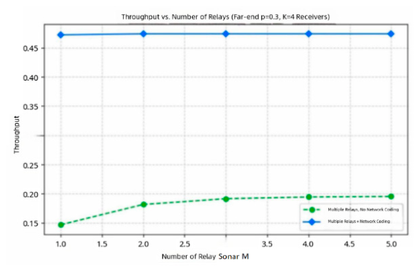
Even if remote-sonar correct-reception probability drops to 0.3, introducing relay-side network coding substantially improves throughput. Increasing relay quantity beyond two brings marginal throughput improvement.
Five schemes are simulated in Figure 10:Case 1: no relay, no network coding (traditional ARQ multicast, lowest efficiency).Case 2: no relay, with network coding. Source directly multicasts with network coding to exploit packet-loss diversity across destinations.Case 3: single relay, no network coding (traditional relay-forward ARQ).Case 4: single relay with network coding (core scheme of this paper). Relay executes network coding before multicasting to remote sonars, obtaining prominent performance improvement.Case 5: multiple relays with network coding. Relays exchange packets among neighbors and perform network coding, achieving the highest transmission efficiency matching Equation (20).
Simulation results confirm that network-coding-enabled systems maintain high throughput even under severe packet-loss conditions.
4. Discussion
Underwater acoustic channels are strongly time-varying and dynamic. Multiple promising directions can extend the current relay-sonar-assisted network-coding multicast system. Adaptive network-coding mechanisms inspired by RL-ANC [11] can be introduced: online channel estimation and acknowledgement feedback estimate real-time packet-loss rates. Reinforcement learning dynamically adjusts maximum encodable-packet number, buffer size and encoding window to approach optimal coding policy under time-variant links. Reinforcement-learning-based sparse-coding parameter tuning can further enhance transmission efficiency under unknown and time-varying underwater links [7]. Moreover, network coding can be jointly optimized with opportunistic routing [14], relay selection, power allocation and deep-learning-driven underwater-channel prediction, providing more accurate packet-loss estimation for coding-decision modules. Future multi-relay systems will integrate above techniques to further improve multicast throughput for multistatic sonar networks.
5. Conclusions
In this paper, five scenarios are investigated: using only relay and using only network coding respectively , and the hybrid scheme combining both network coding and relay sonars. The results reveal that the hybrid scheme achieves the most prominent performance gain. The system gain is jointly affected by buffer size and the maximum encoding number. First, buffer size and the maximum number of encoded packets exert varying influences. When the maximum number of encoded packets is no more than five, the buffer size is proportional to this maximum value. Second, regarding the relationship between buffer size and throughput, throughput rises as the buffer size increases. Third, with a fixed buffer size, throughput varies with the number of pending packets waiting to be encoded; larger numbers of pending packets lead to lower throughput. Fourth, for the relationship between packet-loss rate and transmission bandwidth, higher probability of unreceived packets corresponds to larger transmission bandwidth, implying more packets available for network coding. By contrast, low probability of unreceived packets yields smaller bandwidth with fewer packets for network coding. Network coding delivers the minimum bandwidth occupation.
In summary, under a fixed buffer size and identical packet-loss rate, no performance gain is obtained without relays or network coding. Performance improves when relays are adopted. Relay-only implementation outperforms network-coding-only implementation. The combined use of relays and network coding yields the best performance even under relatively high packet-loss rates. These simulation outcomes are presented in Table 1, which demonstrates that network coding achieves its maximum gain at a moderate packet-loss rate (p ≈ 0.5). For practical underwater acoustic communication applications in high-loss channels, network coding can improve throughput efficiency by 30%-60% (M = 3, p = 0.5-0.9). Larger numbers of receiving ends bring greater benefits from high-order network coding.
Abbreviations
The following abbreviations are used in this manuscript:
| HCAR:HCAR (hybrid-coding-aware routing) |
| RL-ANC:RL-ANC (reinforcement learning-based adaptive network coding) |
| RLNC:RLNC (random linear network coding) |
| ROFC-LF:ROFC-LF (recursive online fountain code with limited feedback) |
| AUV:AUV (autonomous underwater vehicle) |
| UASNs:UASNs (underwater acoustic sensor networks) |
| ARQ:ARQ (automatic repeat request) |
| XOR:XOR (exclusive OR) |
References
- Elias, P.; Feinstein, A.; Shannon, C.E. A note on the maximum flow through a network. IEEE Trans. Inf. Theory 1956, 2, 117–119. [Google Scholar] [CrossRef]
- Lucani, D.E.; Médard, M.; Stojanovic, M. Underwater acoustic networks: channel models and network coding based lower bound to transmission power for multicast. IEEE J. Sel. Areas Commun. 2008, 26, 1708–1719. [Google Scholar] [CrossRef]
- Chitre, M.; Soh, W.S. Network coding to combat packet loss in underwater networks. In Proceedings of the WUWNet 2010, Woods Hole, MA, USA, 30 September–2 October 2010. [Google Scholar]
- Mo, H.; Peng, Z.; Zhou, Z.; Cui, J.H. A two-phase broadcast scheme for underwater acoustic networks. In Proceedings of the IEEE Globecom 2014, Austin, TX, USA, 8–12 December 2014. [Google Scholar]
- Kebkal, V.; Kebkal, O.; Kebkal, K. Network coding for underwater acoustic networks of butterfly topology. In Proceedings of the IEEE OCEANS 2014, St. John’s, NL, Canada, 14–19 September 2014. [Google Scholar]
- Sucasas, V.; Kebkal, O.; Selinis, I.; Seiamak, V.; Mumtaz, S.; Rodriguez, J. Performance of RLNC for underwater broadcasting. IEEE Netw. Lett. 2020, 2, 111–114. [Google Scholar] [CrossRef]
- Gao, R.; Li, Y.; Wang, J.; Quek, T.Q.S. Dynamic sparse coded multi-hop transmissions using reinforcement learning. IEEE Commun. Lett. 2020. [Google Scholar] [CrossRef]
- Li, B. Optimization scheme for physical layer network coding in asymmetric underwater acoustic channels; National Natural Science Foundation of China Research Project, 2021. [Google Scholar]
- Liu, X.; Du, X.; Zhang, J.; Han, D.; Jin, L. ROFC-LF: recursive online fountain code with limited feedback for underwater acoustic networks. IEEE Trans. Commun. 2022, 70, 4327–4342. [Google Scholar] [CrossRef]
- Wang, H.; et al. AUV-assisted stratified source location privacy protection scheme based on network coding in UASNs. IEEE Internet Things J. 2023, 10, 10636–10647. [Google Scholar] [CrossRef]
- Zhang, Y.; Wang, X. RL-ANC: reinforcement learning-based adaptive network coding in the ocean mobile internet of things. J. Mar. Sci. Eng. 2024, 12, 998. [Google Scholar] [CrossRef]
- Su, P.; Yang, S. On the stochastic analysis of random linear streaming codes in multi-hop relay networks. IEEE Trans. Commun. 2025, 73, 7892–7905. [Google Scholar] [CrossRef]
- Zhang, Z.L.; Pu, Z.Q.; Zhu, Y.N.; et al. Random-linear-network-coding-based cooperative reliable transmission protocol for underwater acoustic communication networks. J. Electron. Inf. Technol. 2025. [Google Scholar] [CrossRef]
- Ren, J.; Wu, Y.B.; Zhu, M.; Li, X.Y. Cross-layer cooperative design of network coding and distributed opportunistic routing for underwater acoustic sensor networks. IEEE Sens. J. 2026, 26, 1329–1346. [Google Scholar] [CrossRef]
- Zhuang, H.; Valera, A.; Eu, Z.A.; Lee, P.W.Q.; Tan, H.P. Opportunistic XOR network coding for multihop data delivery in underwater acoustic networks. In Proceedings of the IEEE OCEANS 2011, Santander, Spain, 6–9 June 2011. [Google Scholar]
- Katti, S.; Rahul, H.; Hu, W.; Katabi, D.; Médard, M.; Crowcroft, J. XORs in the air: practical wireless network coding. In Proceedings of the ACM SIGCOMM 2006, Pisa, Italy, 11–15 September 2006; pp. 243–254. [Google Scholar]
- Su, Y.; Xu, Y.; Pang, Z.; Kang, Y.; Fan, R. HCAR: a hybrid-coding-aware routing protocol for underwater acoustic sensor networks. IEEE Internet Things J. 2023, 10, 19218–19229. [Google Scholar] [CrossRef]
- Fan, P.; Chen, Z.; Chen, W.; Letaief, K.B. Reliable relay assisted wireless multicast using network coding. IEEE J. Sel. Areas Commun. 2009, 27, 749–763. [Google Scholar] [CrossRef]
- Chen, H.; Zhang, Z.; Qiu, P.; Lau, V.K.N. Cooperative spectrum access for cognitive radio network employing rateless code. In Proceedings of the IEEE ICC Workshops 2008, Beijing, China, 19–23 May 2008; pp. 326–331. [Google Scholar]
- Chi, K.; Jiang, X.; Horiguchi, S. Network coding-based reliable multicast in wireless networks. Comput. Netw. 2010, 54, 1823–1836. [Google Scholar] [CrossRef]
- Le, J.; Lui, J.C.S.; Chiu, D.M. How many packets can we encode? — An analysis of practical wireless network coding. In Proceedings of the IEEE INFOCOM 2008, Phoenix, AZ, USA, 13–18 April 2008; pp. 371–375. [Google Scholar] [CrossRef]
Figure 1.
Cooperative relay-sonar underwater acoustic multicast system.
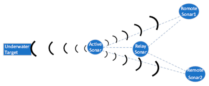
Figure 2.
Block diagram of the relay-sonar-assisted multicast system based on network coding.
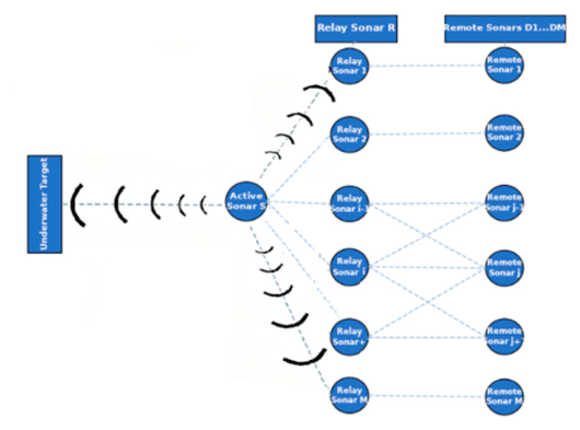
Figure 3.
Packets received by relay sonar r and remote sonars 1, 2, 3. Red-underlined entries denote received packets.
Figure 3.
Packets received by relay sonar r and remote sonars 1, 2, 3. Red-underlined entries denote received packets.
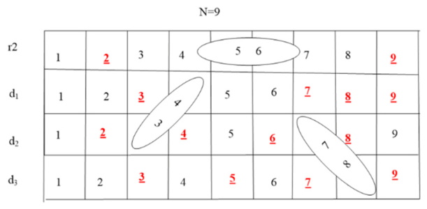
Figure 4.
Transmission workflow: active-sonar source, relay-side network coding, remote receiving sonars.
Figure 4.
Transmission workflow: active-sonar source, relay-side network coding, remote receiving sonars.
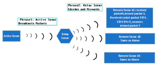
Figure 5.
Relationship between buffer size and maximum encodable-packet number.
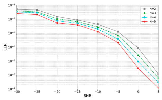
Figure 6.
Relationship between buffer size and throughput.
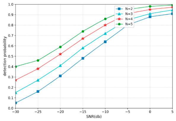
Figure 7.
Relationship between transmission bandwidth and packet-loss probability.
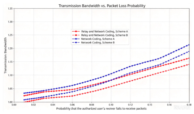
Figure 10.
Throughput versus packet-loss probability for five representative schemes.
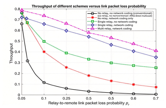

Table 1.
Limiting cases and gain expressions.
| Limiting case | Gain expression | |
|---|---|---|
| p→0 |
Negligible gain | |
| p→1 | HM is the harmonic number; | |
| p→0.5,M=3 | G3 = 1.25 | 25%improvement |
| p→0.5,M=5 |
G3 = 1.59 | 59%improvement |
Disclaimer/Publisher’s Note: The statements, opinions and data contained in all publications are solely those of the individual author(s) and contributor(s) and not of MDPI and/or the editor(s). MDPI and/or the editor(s) disclaim responsibility for any injury to people or property resulting from any ideas, methods, instructions or products referred to in the content. |
© 2026 by the authors. Licensee MDPI, Basel, Switzerland. This article is an open access article distributed under the terms and conditions of the Creative Commons Attribution (CC BY) license (http://creativecommons.org/licenses/by/4.0/).
Copyright: This open access article is published under a Creative Commons CC BY 4.0 license, which permit the free download, distribution, and reuse, provided that the author and preprint are cited in any reuse.