

Submitted:
05 October 2026
Posted:
08 October 2026
You are already at the latest version
Abstract
Orthogonal fluxgate sensors can measure static and low-frequency magnetic fields at room temperature and are valuable for geomagnetic exploration, navigation and positioning, and target recognition. In response to the sensitivity degradation and noise increase associated with device miniaturization, this paper presents a micro orthogonal fluxgate sensor fabricated via MEMS technology, comprising a meander-shaped Cu/FeNi composite core and a three-dimensional solenoidal sensing coil. The performance of four sensors—Sensor A (4 core strips and 4.5 mm long, with a 40-turn sensing coil), Sensor B (4 core strips and 8.5 mm long, with an 80-turn sensing coil), Sensor C (10 core strips and 4.5 mm long, and a 40-turn sensing coil), and Sensor D (10 core strips and 8.5 mm long, with an 80-turn sensing coil)—was compared in fundamental mode. Under the optimized test conditions, Sensor D exhibited the best overall performance, with a sensitivity of 133.8 V/T and an equivalent magnetic-field noise spectral density of 0.67 nT/√Hz @ 1 Hz. During a 1 h test, its average zero offset was approximately 125 nT, with a maximum peak-to-peak variation of approximately 10 nT. Comparison of the four structures indicates that, within the tested designs, increasing the number of core strips and combining longer strips with more sensing-coil turns can help achieve high sensitivity and low noise in micro orthogonal fluxgate sensors.
Keywords:
orthogonal fluxgate sensor
; fundamental-mode operation
; sandwich-structured core
; spatial magnetic-field measurement
1. Introduction
As a traditional high-precision magnetic field sensor,fluxgate sensors can measure static and low-frequency magnetic fields at room temperature and offer high sensitivity and good stability, and they play an important role in geomagnetic exploration, navigation and positioning, and target recognition [1]. Among various fluxgate sensors, the orthogonal fluxgate sensor features a simple structure, compact size, and low power consumption [2], and offers better spatial resolution in magnetic field measurement, making it an excellent choice for the detection of biological nanomagnetic materials [3], weak magnetic fields in micro-region detection, and geomagnetic navigation. Orthogonal fluxgate sensors use a current flowing through the core to generate a circumferential excitation field and a sensing coil to detect an axial external field [4]. Moreover, integrated MEMS orthogonal fluxgate sensor technology maximizes the benefits of miniaturization [5]. However, as device size decreases, the space available for the core and sensing coil becomes limited, and reduced sensitivity and increased noise continue to constrain the performance of micro orthogonal fluxgate sensors [6].
The operating mode and core material are important considerations in improving the performance of orthogonal fluxgate sensors. Early orthogonal fluxgate sensors mainly operated in the second-harmonic mode, in which the core periodically switches between opposite magnetization states. The resulting Barkhausen noise is unfavorable for weak-field measurement [7]. The fundamental mode introduced later uses a DC bias to keep the core magnetized predominantly in one direction, providing a means of reducing noise [8]. Meanwhile, Co-based amorphous alloys have been widely used in high-performance orthogonal fluxgate sensors because of their favorable soft magnetic properties [9,10,11]. FeNi alloys can be prepared by electroplating and are compatible with MEMS fabrication [12], although their magnetic properties may limit the performance of miniature devices. The operating mode and core material must therefore be considered together with the specific device structure [13].
In addition to the material, the structure and geometry of the core affect the magnetic response of the sensor. Previous studies have used Cu/FeNi composite wire cores, in which the Cu conductor provides a path for the excitation current and FeNi forms the soft magnetic component [14]. However, miniature devices using such cores still face insufficient sensitivity. To improve the core response, multicore, U-shaped, and S-shaped structures have been proposed [15]. In a meander-shaped core, the number, width, and spacing of the strips can be adjusted to alter the demagnetization effect and the effective sensing area. Previous simulations have shown that the effects of these parameters on sensitivity are not always monotonic [16], indicating that core geometry must be chosen according to device size and measurement requirements.
The sensing coil is another important part of a micro orthogonal fluxgate sensor. MEMS photolithography and electroplating have enabled the integrated fabrication of micro cores and coils [17]. Both planar sensing coils and three-dimensional solenoidal sensing coils have been used in previous devices [18]. Planar coils are relatively straightforward to fabricate, but their geometry limits how effectively they sense changes in core flux. Three-dimensional solenoidal coils can surround the core and may improve the induced output [19]. S-shaped cores have also been combined with three-dimensional coils. These developments indicate that the combination of core and coil structures affects device performance and motivate further investigation of structures suitable for Cu/FeNi composite cores.
To investigate the optimization design principles for high-sensitivity and low-noise MEMS orthogonal fluxgate sensors, this paper presents a micro orthogonal fluxgate sensor fabricated via MEMS technology, comprising a meander-shaped Cu/FeNi composite core and a three-dimensional solenoidal sensing coil. Four structural variants were developed and tested to investigate the effects of device structure on the sensor’s performance in fundamental mode operation.
2. Design and Fabrication
An orthogonal fluxgate sensor mainly consists of a soft magnetic core and a sensing coil. The excitation current flows along the core axis and generates a circumferential excitation magnetic field, whereas the external magnetic field to be measured is directed along the core axis, making the two fields mutually orthogonal. The periodic excitation current causes the magnetization state and permeability of the core to vary with time, while the axial external magnetic field produces a periodic variation in the axial magnetization component, thereby inducing a voltage in the sensing coil. In this study, the sensor was operated in fundamental mode, with the excitation current consisting of an AC component, Iac, and a DC bias component, Idc. The DC bias maintains the core in a unipolar saturated state, while the AC component causes the magnetization direction to deflect periodically. The sensing coil generates a fundamental voltage at the excitation frequency, whose amplitude is approximately proportional to the external magnetic field within the linear operating range [20]. This mode eliminates repeated switching of the core between positive and negative saturation states, thereby helping reduce Barkhausen noise caused by magnetization reversal.
The magnetic properties of the core material directly affect sensor performance. Electroplated FeNi alloys exhibit favorable soft magnetic properties and offer accurate and controllable thickness. Meanwhile, electroplated FeNi alloy process is compatible with MEMS processes at relatively low fabrication cost, and is easy to achieve complex geometric shape designs, making it suitable for micro orthogonal fluxgate cores. A single rod-shaped FeNi core for an orthogonal fluxgate sensor suffers from zero drift, eddy current loss and magnetic crosstalk. As shown in the inset of Figure 1, where FeNi thin films are deposited on both the top and bottom surfaces of a Cu wire, the single-wire Cu/FeNi sandwich core leverages eddy-current shielding and differential magnetization of the Cu interlayer to suppress crosstalk and reduce losses, thereby improving the noise performance of the MEMS orthogonal fluxgate sensor.
Miniaturization reduces the effective cross-sectional area of the magnetic core and may consequently decrease sensor sensitivity. Therefore, multiple core strips were connected to form a meander structure, increasing the total core cross-sectional area within a limited chip footprint. Adjacent strips were joined by arc-shaped sections to reduce abrupt changes in the magnetization direction at the bends. Because the number, width, and spacing of the core strips affect both the demagnetization effect and sensor sensitivity, these parameters should be carefully selected by balancing the core dimensions against the demagnetization effect. Accordingly, a micro orthogonal fluxgate sensor comprising a meander-shaped Cu/FeNi composite core and a three-dimensional solenoidal sensing coil was designed, as shown in Figure 1. Four sensor configurations were constructed by varying the number and length of the core strips, which were employed to investigate the optimization design principles of the sensor while comprehensively considering factors such as core dimensions, demagnetization effects, and coil architecture.
The fabrication process is illustrated in Figure 2. First, a 100-nm-thick Cr/Cu seed layer was sputtered, as shown in Figure 2a. A 20-μm-thick bottom coil conductor and Cu interconnect pillars were then successively formed by photolithography and Cu electroplating, as shown in Figure 2b. After removing the photoresist and Cr/Cu seed layer, polyimide was spin-coated, cured, ground, and polished to expose the Cu pillars and obtain a planar polyimide surface, as shown in Figure 2c. Subsequently, a Cr/Cu seed layer is sputtered again. A 4-μm-thick lower FeNi film was formed by photolithography and electroplating, as shown in Figure 2d. A 6-μm-thick central Cu conductor was then fabricated on the lower FeNi film, as shown in Figure 2e. An upper FeNi film was subsequently formed above the central Cu conductor. The upper and lower FeNi films were joined to enclose the central Cu conductor, thereby forming the Cu/FeNi sandwich core, as shown in Figure 2f. Cu interconnect pillars with a height of 20 μm were then fabricated with their tops approximately 5 μm above the Cu/FeNi core, as shown in Figure 2g. After removing the photoresist and Cr/Cu seed layer, another polyimide layer was spin-coated, cured, ground, and polished to expose the Cu pillars and obtain a planar surface, as shown in Figure 2h. After sputtering a Cr/Cu seed layer, a 20-μm-thick top coil conductor and electrode were electroplated using the same process, as shown in Figure 2i. Finally, a polyimide protective layer was fabricated while leaving the Cu electrodes exposed, as shown in Figure 2j. The processed substrate was then diced using a precision dicing machine to obtain the micro orthogonal fluxgate sensor chips.
Four micro orthogonal fluxgate sensors with different Cu/FeNi-core structures were fabricated using the process described above, and their micrographs are shown in Figure 3. The excitation conductors were made of electroplated Cu, with a linewidth, thickness, and spacing of 50 μm, 6 μm, and 150 μm, respectively. The FeNi core strips had a width and spacing of 100 μm, while both the upper and lower FeNi layers were 4 μm thick. The sensing coils had a linewidth, thickness, and spacing of 50 μm, 20 μm, and 50 μm, respectively. Sensors A and C contained 4 and 10 core strips, respectively, with a core-strip length of 4.5 mm and 40-turn sensing coils. Sensors B and D contained 4 and 10 core strips, respectively, with a core-strip length of 8.5 mm and 80-turn sensing coils. The dimensions of Sensors A, B, C, and D were 5.9 mm × 3.5 mm, 9.9 mm × 3.5 mm, 5.9 mm × 4.3 mm, and 9.9 mm × 4.3 mm, respectively; the resistances of Cu/FeNi-core were 1.2, 2.3, 3.2, and 6.1 Ω, respectively, while sensing coil resistances were 1.8, 3.4, 3.0, and 5.9 Ω, respectively; all Cu electrodes had dimensions of 1 mm × 1 mm.
3. Performance Testing of THE Chips
The sensor was characterized in fundamental mode with an open-loop testing system, as shown in Figure 4. A function signal generator (Tektronix AFG 3022) was used to generate a sinusoidal excitation signal, which was then amplified by a power amplifier (NF BA4825) and applied to the sensor. A lock-in amplifier (SR844 DSP) was used to measure the fundamental-frequency component of the pick-up coil voltage. To provide a DC test magnetic field, a manually wound copper solenoid coil was employed, with its magnitude controlled by adjusting the current supplied from a source meter. During testing, both the sensor and the solenoid coil were placed inside a cylindrical shield composed of six layers of soft magnetic ribbons, with the center axis of the sensor’s sensing coil aligned parallel to that of the solenoid. Furthermore, the shield’s axis was oriented perpendicular to the Earth’s magnetic field, while remaining parallel to the sensing coil’s axis.
3.1. Excitation Frequency Effect
At an AC excitation current of Iac = 200 mA and a DC bias current of Idc = 300 mA, the sensitivities of four Cu/FeNi-core orthogonal fluxgate sensors were measured by varying the excitation frequency from 100 to 600 kHz, as shown in Figure 5. With increasing excitation frequency, the sensitivities of all four sensors initially increased and subsequently decreased. Throughout the investigated frequency range, Sensor D exhibited the highest sensitivity, followed by Sensors C and B, whereas Sensor A showed the lowest sensitivity. Sensor A reached a maximum sensitivity of approximately 41 V/T at 300 kHz, while Sensors B, C, and D achieved their maximum sensitivities of approximately 60, 85, and 133 V/T, respectively, at 400 kHz. At 400kHz, the sensitivity of Sensor D was approximately 3.6 times that of Sensor A. Therefore, 400 kHz was identified as the optimal operating frequency for the sensors and was adopted as the unified operating frequency in all subsequent experiments. When the operating frequency exceeds 400 kHz, eddy currents and skin effects lead to a decrease in the sensor’s sensitivity.
3.2. Excitation Current Effect
Under fundamental-mode operation, the sensitivity of an orthogonal fluxgate sensor is simultaneously influenced by the AC excitation current Iac and the DC bias current Idc. To investigate the effects of these two currents on sensor sensitivity, experiments were conducted by varying the AC excitation current and the DC bias current separately. The experimental results are presented in Figure 6.
With the DC bias current Idc fixed at 350 mA, the AC excitation current Iac was gradually increased from 50 to 300 mA. As shown in Figure 6a, the sensitivities of all four orthogonal fluxgate sensors with Cu/FeNi cores increased continuously with increasing Iac, exhibiting an overall monotonic upward trend. Throughout the tested current range, the sensitivity ranking of the four sensors remained unchanged, with Sensor D exhibiting the highest sensitivity, followed by Sensors C, B, and A.
With the AC excitation current Iac fixed at 200 mA, the DC bias current Idc was gradually increased from 250 to 500 mA. As illustrated in Figure 6b, the sensitivities of all four sensors gradually decreased with increasing Idc. During this process, their relative sensitivity ranking remained unchanged: Sensor D exhibited the highest sensitivity, followed by Sensors C, B, and A.
According to the operating principle of the fundamental-mode orthogonal fluxgate sensor, the amplitude of the DC bias current must always exceed that of the AC excitation current. Increasing the AC excitation current can effectively enhance sensor sensitivity, whereas increasing the DC bias current reduces it. At the same time, excessive currents introduce significant thermal noise. Therefore, in fundamental-mode operation, it is essential to match properly the AC excitation and DC bias currents to achieve an optimal trade-off between sensitivity and noise performance. As shown in Figure 5, when the AC excitation current is 200 mA and the DC bias current is 300 mA, all four sensors exhibit favorable sensitivity levels.
3.3. Output Response and Noise Performance
The performance of four orthogonal fluxgate sensors with different Cu/FeNi core structures was evaluated at an AC excitation current of Iac = 200 mA, a DC bias current of Idc = 300 mA, and an excitation frequency of f = 400 kHz. The output response curves and noise spectral density curves are presented in Figure 7 and Figure 8, respectively, and the corresponding performance parameters are summarized in Table 1.
As shown in Figure 7, the output voltages of all four sensors initially increase approximately linearly with the applied magnetic field. As the magnetic field increases further, the output responses gradually deviate from linearity and approach saturation. Clear differences are observed among the four sensor structures, with the sensitivities decreasing in the order of Sensor D, Sensor C, Sensor B, and Sensor A. As listed in Table 1, the sensitivities of Sensors A, B, C, and D are 37.5, 59.4, 85.1, and 133.8 V/T, respectively, with Sensor D exhibiting the highest sensitivity. The linear range of Sensors A, B, C, and D is 300, 210, 420, and 330 μT, respectively, with Sensor C exhibiting the widest linear range.
Figure 8 shows that the equivalent magnetic-field noise of all four sensors generally decreases with increasing frequency, although fluctuations are observed over the tested frequency range. Sensor D exhibits the lowest overall noise level, followed by Sensor C, whereas Sensor A shows the highest noise level. As listed in Table 1, the noise of Sensors A, B, C, and D is 2.81, 1.51, 1.07, and 0.67 nT/√Hz, respectively, with Sensor D exhibiting the lowest noise level.
A comparison of the noise spectral density curves in Figure 8 with the corresponding noise values at 1 Hz in Table 1 reveals an overall inverse relationship between sensitivity and noise. Specifically, the equivalent magnetic-field noise decreases as the sensor sensitivity increases. Considering sensitivity, linear range, and low-frequency noise together, Sensor D provides the best overall performance, exhibiting the highest sensitivity, the lowest noise level, and proper linear range.
3.4. Zero Offset Drift
A continuous 1 h zero-offset stability test was conducted on Sensor D in a magnetically shielded environment without an externally applied magnetic field. During the test, the excitation frequency f was set to 400 kHz, the AC excitation current Iac to 200 mA, and the DC bias current Idc to 300 mA. As shown in Figure 9, the average zero-offset value of Sensor D was approximately 125 nT throughout the test, with a maximum variation of approximately 10 nT, indicating good zero-offset stability.
The zero offset may be primarily attributed to the magnetostrictive effect of the magnetic core. In addition, slight changes in temperature and internal stress during the test may alter the magnetic properties of the core, thereby causing fluctuations in the output signal. Therefore, soft magnetic alloys with near-zero magnetostriction can be employed, together with further optimization of the core fabrication process and sensor structure, to reduce the zero offset and improve the long-term stability of the sensor.
3.5. Perming Error Characteristics
To investigate the perming error of the Cu/FeNi-core orthogonal fluxgate sensor, Sensor D was tested at an excitation frequency of 400 kHz under different AC excitation currents Iac and DC bias currents Idc. For each set of excitation conditions, a magnetic field of approximately 10 mT was first applied along the sensitive axis of the sensor for 3 s. After the magnetic field was removed, the fundamental-frequency output voltage was measured. A magnetic field of the same magnitude was then applied in the opposite direction for 3 s, and the output voltage was measured again after field removal. The perming error was determined by dividing the difference between the two fundamental-frequency output voltages by the sensor sensitivity. The results are shown in Figure 10.
At Idc = 300 mA, as Iac increased from 50 to 250 mA, the perming error continuously decreased from approximately 22.5 to 7.1 μT, reaching its minimum value at the highest tested Iac of 250 mA. These results indicate that increasing the AC excitation current enhances the cyclic magnetization of the magnetic core and reduces the influence of residual magnetization induced by strong- field exposure on the sensor offset [21], thereby effectively suppressing the perming error.
At Iac = 150 mA, the perming error initially increased and then decreased with increasing Idc. However, the overall variation was relatively small, with an average perming error of approximately 11 μT and a difference of about 4μT between the maximum and minimum values. Compared with the AC excitation current, the DC bias current had a less pronounced effect on the perming error.
4. Conclusion
Four orthogonal fluxgate sensors with different Cu/FeNi composite core structures were fabricated using MEMS processes: Sensor A (4 core strips, each 100 μm wide and 4.5 mm long, with a 40-turn sensing coil), Sensor B (4 core strips, each 100 μm wide and 8.5 mm long, with an 80-turn sensing coil), Sensor C (10 core strips, each 100 μm wide and 4.5 mm long, with a 40-turn sensing coil), and Sensor D (10 core strips, each 100 μm wide and 8.5 mm long, with an 80-turn sensing coil). The effects of device structure and excitation conditions on sensor performance were investigated. The sensors ranked D, C, B, and A in descending order of sensitivity and ascending order of noise power spectral density at 1 Hz. At an excitation frequency of 400 kHz, an AC excitation current of Iac = 200 mA, and a DC bias current of Idc = 300 mA, Sensor D achieved a sensitivity of 133.8 V/T, an equivalent magnetic-field noise spectral density of 0.67 nT/√Hz@1Hz, and a linear range of 0–330 μT, providing the best overall performance among the four sensors. At Idc = 300 mA, its perming error decreased from approximately 22.5 to 7.1 μT as Iac increased from 50 to 250 mA. During a 1 h test under the stated operating conditions, its zero offset was approximately 125 nT, with a maximum variation of approximately 10 nT. Comparison of the four structures showed that a greater number of core strips, as well as the combination of longer strips and more sensing-coil turns, was associated with higher sensitivity and lower noise. These results will be helpful for the design of high-sensitivity, low-noise orthogonal fluxgate sensors.
The low permeability of the electroplated FeNi core limits the performance of sandwich-core orthogonal fluxgate sensors, resulting in lower sensitivity and higher noise than those of conventional commercial fluxgate sensors. The amorphous soft-magnetic ribbons with high-permeability, and nearly zero-magnetostriction have already been successfully applied in the design of MEMS orthogonal fluxgate sensors. In future work, a sandwich core that combines amorphous soft-magnetic ribbons with copper conductors is expected to substantially increase the sensitivity and reduce the noise of MEMS orthogonal fluxgate sensors, thereby contributing to the development of the sensor products suitable for real-world market deployment.
References
- Wei, S.; Liao, X.; Zhang, H.; Pang, J.; Zhou, Y. Recent Progress of Fluxgate Magnetic Sensors: Basic Research and Application. Sensors 2021, 21, 1500. [CrossRef]
- Priftis, P.; Angelopoulos, S.; Ktena, A.; Hristoforou, E. Development of a High-Sensitivity Orthogonal Fluxgate Sensor. J. Magn. Magn. Mater. 2024, 590, 171646. [CrossRef]
- Pu, X.; Sheng, Z.; Yu, Z.; Li, H.; Wei, X.; Yang, T.; Liu, Q.; Chai, G.; Liang, X.; Gao, D. Ultralow Noise Orthogonal Fluxgates Enabling Weak Magnetic Field and Biomolecular Detection. Nano-Micro Lett. 2027, 19, 19. [CrossRef]
- Kim, K.-W.; Hong, S.-M.; Lee, D.; Shin, K.-H.; Lim, S.H. Micro Orthogonal Fluxgate Sensor Fabricated with Amorphous CoZrNb Film. Sensors 2025, 25, 5022. [CrossRef]
- Ma, Q.; Dai, Y.; Wu, T.; Chen, H.; Sun, X.; Lei, C. A Multidimensional Integrated Micro Three-Component Fluxgate Sensor Based on Microelectromechanical System Technology. Sens. Actuators Phys. 2024, 371, 115315. [CrossRef]
- Marconato, N. Design of Integrated Micro-Fluxgate Magnetic Sensors: Advantages and Challenges of Numerical Analyses. Sensors 2022, 22, 961. [CrossRef]
- Zhi, S.; Feng, Z.; Lei, C. Improved Performance of Fundamental Mode Orthogonal Fluxgate Using a Micro-Patterned Meander-Shaped Ribbon Core. Sensors 2019, 19, 5058. [CrossRef]
- Murata, N.; Karo, H.; Sasada, I.; Shimizu, T. Fundamental Mode Orthogonal Fluxgate Magnetometer Applicable for Measurements of DC and Low-Frequency Magnetic Fields. IEEE Sens. J. 2018, 18, 2705–2712. [CrossRef]
- Butta, M.; Janošek, M.; Pařez, J.; Inchausti, A.V.; Chiriac, H. An Improved Composition of CoFeSiB Alloy for Orthogonal Fluxgates. Sensors 2022, 22, 2162. [CrossRef]
- Murata, N.; Nomura, R.; Matsuoka, A. Current Annealing of Amorphous Wire Core for Performance Improvement of Fundamental Mode Orthogonal Fluxgate. J. Magn. Magn. Mater. 2019, 484, 497–503. [CrossRef]
- Wang, B.; Xu, W.; Zheng, X.; Jiang, S.; Yi, Z.; Wang, P.; Tang, X. Performance of Fluxgate Magnetometer with Cu-Doped CoFeSiB Amorphous Microwire Core. Sensors 2024, 24, 309. [CrossRef]
- Heimfarth, T.; Mulato, M. Miniature Orthogonal Fluxgate Sensor in Rotation Magnetization Mode: Modeling and Characterization. Sens. Actuators Phys. 2018, 279, 113–119. [CrossRef]
- Pu, X.; Yu, Z.; Gao, J.; Zhong, M.; Wang, L.; Xiao, W.; Chai, G.; Gao, D. Heterogeneous Assembly of Graded Magnetic Composite Wires for Noise Suppression in Orthogonal Fluxgate. Sens. Actuators Phys. 2025, 394, 116899. [CrossRef]
- Pu, X.; Zhou, Q.; Chai, G.; Gao, D. Optimization of U-Shaped Cu@ Fe20Ni80 Core for Orthogonal Fluxgate Sensor. J. Magn. Magn. Mater. 2024, 592, 171822. [CrossRef]
- Zhi, S.; Feng, Z.; Guo, L.; Lei, C.; Zhou, Y. Investigation of a Novel MEMS Orthogonal Fluxgate Sensor Fabricated with Co-Based Amorphous Ribbon Core. Sens. Actuators Phys. 2017, 267, 121–126. [CrossRef]
- Zhi, S.; Sun, X.; Zhang, Q.; Chen, J.; Zhang, X.; Chen, H.; Lei, C. Demagnetization Effect in a Meander-Core Orthogonal Fluxgate Sensor. Micromachines 2021, 12, 937. [CrossRef]
- Guo, L.; Wang, C.; Zhi, S.; Feng, Z.; Lei, C.; Zhou, Y. Wide Linearity Range and Highly Sensitive MEMS-Based Micro-Fluxgate Sensor with Double-Layer Magnetic Core Made of Fe–Co–B Amorphous Alloy. Micromachines 2017, 8, 352. [CrossRef]
- Maier, J.; Ripka, P.; Chen, P. CMOS-Based Micro-Fluxgate with Racetrack Core and Solenoid Coils. Sens. Actuators Phys. 2024, 379, 115886. [CrossRef]
- Yang, Y.; Xu, W.; Chen, G.; Jin, Z.; Wang, D.; Mai, Z.; Xing, G.; Chen, J. MEMS Fluxgate Sensor Based on Liquid Casting. Micromachines 2023, 14, 2159. [CrossRef]
- Yuan, Z.; Zhang, Y.; Wang, D.; Jiang, Y.; Guo, R. Research on the Orthogonal Fundamental Mode Fluxgate Sensor Circuit. IEEE Access 2020, 8, 150665–150671. [CrossRef]
- Butta, M.; Dressler, M.; Janosek, M. Offset Drift in Orthogonal Fluxgate and Importance of Closed-Loop Operation. Sens. Actuators Phys. 2022, 342, 113583. [CrossRef]
Figure 1.
The schematic view of micro orthogonal fluxgate sensor based on Cu/FeNi core.
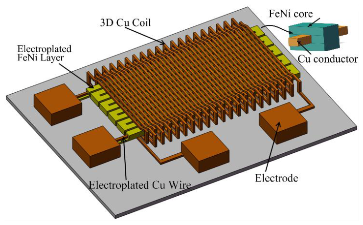
Figure 2.
The fabrication process flow of micro orthogonal fluxgate sensor based on Cu/FeNi core.
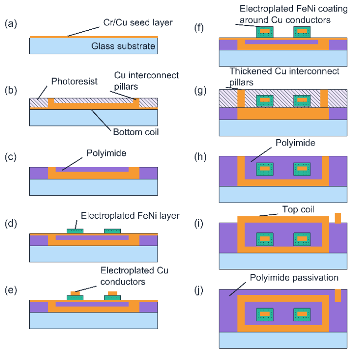
Figure 3.
Micrographs of the fabricated micro orthogonal fluxgates based on Cu/FeNi cores with four different structures.
Figure 3.
Micrographs of the fabricated micro orthogonal fluxgates based on Cu/FeNi cores with four different structures.
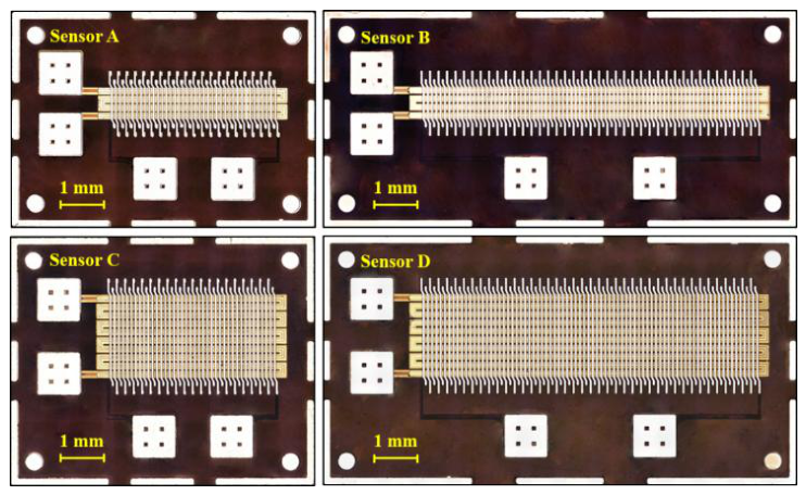
Figure 4.
Test system process.
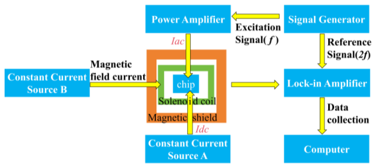
Figure 5.
Effect of excitation frequency on the sensitivity of four Cu/FeNi-core orthogonal fluxgate sensors.
Figure 5.
Effect of excitation frequency on the sensitivity of four Cu/FeNi-core orthogonal fluxgate sensors.
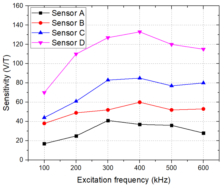
Figure 6.
Effects of excitation current and DC bias current on sensor sensitivity: (a) AC excitation current Iac;.(b) DC bias current Idc.
Figure 6.
Effects of excitation current and DC bias current on sensor sensitivity: (a) AC excitation current Iac;.(b) DC bias current Idc.
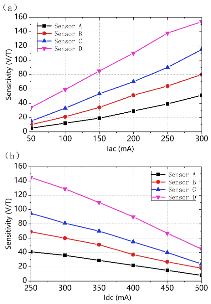
Figure 7.
Output response curves of four orthogonal fluxgate sensors with different core structures.
Figure 7.
Output response curves of four orthogonal fluxgate sensors with different core structures.
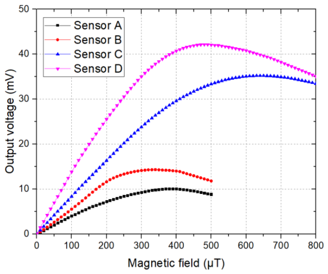
Figure 8.
Noise spectral density of four orthogonal fluxgate sensors with different core structures.
Figure 8.
Noise spectral density of four orthogonal fluxgate sensors with different core structures.
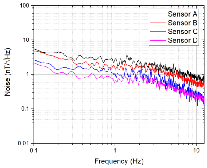
Figure 9.
Offset stability of the sensor.
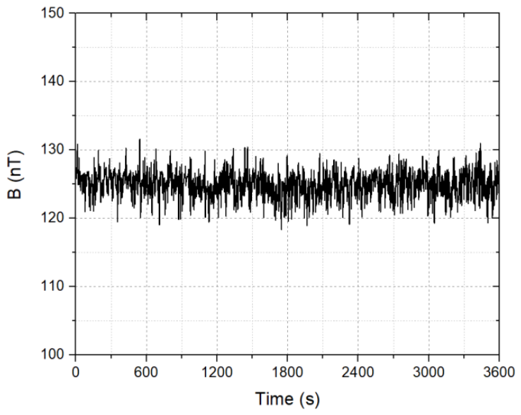
Figure 10.
Effect of excitation frequency on the sensitivity of four Cu/FeNi-core orthogonal fluxgate sensors.
Figure 10.
Effect of excitation frequency on the sensitivity of four Cu/FeNi-core orthogonal fluxgate sensors.
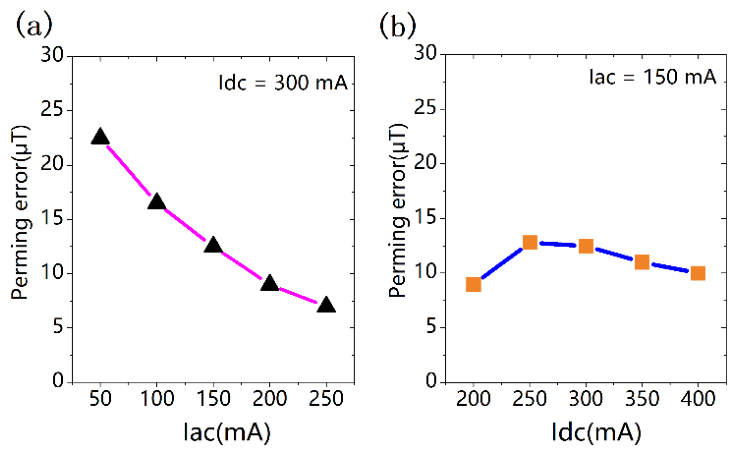

Table 1.
Performance of four orthogonal fluxgate sensors with different core structures.
| Sensor type | Sensitivity (V/T) | Linear range (0–μT) | 1 Hz noise (nT/√Hz) |
| Sensor A | 37.5 | 300 | 2.81 |
| Sensor B | 59.4 | 210 | 1.51 |
| Sensor C | 85.1 | 420 | 1.07 |
| Sensor D | 133.8 | 330 | 0.67 |
Disclaimer/Publisher’s Note: The statements, opinions and data contained in all publications are solely those of the individual author(s) and contributor(s) and not of MDPI and/or the editor(s). MDPI and/or the editor(s) disclaim responsibility for any injury to people or property resulting from any ideas, methods, instructions or products referred to in the content. |
© 2026 by the authors. Licensee MDPI, Basel, Switzerland. This article is an open access article distributed under the terms and conditions of the Creative Commons Attribution (CC BY) license (http://creativecommons.org/licenses/by/4.0/).
Copyright: This open access article is published under a Creative Commons CC BY 4.0 license, which permit the free download, distribution, and reuse, provided that the author and preprint are cited in any reuse.