
Submitted:
03 October 2026
Posted:
06 October 2026
You are already at the latest version
Abstract
To investigate the influence of blade-tip height deviations caused by machining errors and overhaul wear on compressor aerodynamic performance, numerical simulations are performed on the transonic axial compressor NASA Rotor 37. With a fixed average tip clearance, ten circumferentially non-uniform tip clearance cases are designed and classified into three categories: globally reduced clearance, globally increased clearance, and mixed clearance variation. The results reveal that the circumferential distribution direction of non-uniform tip clearance has a remarkable impact on both the compressor stability margin and aerodynamic efficiency. The clearance distribution pattern that decreases gradually against the rotor rotation direction outperforms the increasing pattern in terms of both aerodynamic performance and stability margin. For the mixed clearance cases with the same average clearance as the baseline compressor, the scheme with clearance decreasing against the rotation direction achieves a 0.24% higher peak efficiency than the baseline, with nearly unchanged stability margin. Unlike casing-deformation-induced non-uniform clearance, this work targets tip-height inconsistency from manufacturing and overhaul. Internal flow analysis indicates that the compressor stability margin is governed by the blade passage with the maximum flow blockage. The abrupt deceleration of leakage flow propagating from a large-clearance sector to an adjacent small-clearance sector is the primary cause of aggravated local blockage and stall onset. This work provides numerical guidance for blade assembly sequencing of transonic axial compressors.
Keywords:
transonic axial compressor
; circumferential non-uniform tip clearance
; blade sequencing
; numerical simulation
1. Introduction
As one of the core components of an aero-engine, the axial compressor directly determines the engine’s thrust-to-weight ratio, fuel economy, and service life. The tip clearance between rotor blades and the casing is unavoidable, since it is jointly governed by rotational centrifugal force, thermal expansion, and manufacturing and assembly tolerances. Therefore, in the design and operation of an axial compressor, the tip clearance is a key parameter that cannot be ignored. This tip clearance induces leakage flow driven by the pressure difference between the blade pressure side and suction side. Such leakage flow interacts with the main flow and passage shock waves, forming complex tip leakage vortex structures that produce considerable aerodynamic losses [1,2,3] and may trigger unstable flow phenomena including rotating stall and flutter.
Research on tip clearance can be summarized into two aspects. On the one hand, many scholars have carried out extensive research on the flow within the tip clearance and its effects. With the continuous improvement of performance requirements for modern aero-engines, transonic and high-load operation has become the mainstream development direction of axial compressors. In the tip clearance of such compressors, the leakage vortex and the passage shock wave interact with each other, forming a complex flow field structure that has a decisive influence on the aerodynamic performance and stability margin of the compressor. Storer and Cumpsty reported that the mixing of passage main flow and tip leakage flow generates tip leakage losses [4]. Inoue et al. stated that tip leakage flow originates from the pressure difference across the blade tip, jets from the pressure side to the suction side, and mixes with the main flow; its development is influenced by the casing end wall, inlet boundary layer, and rotor passage secondary flows [5]. On the other hand, some scholars have focused on the research of tip clearance morphology and its effects. Traditional studies usually assume that the tip clearance is uniformly distributed along both the axial and circumferential directions, but due to the influence of numerous factors such as high-speed rotation centrifugal force, rubbing, deformation, machining deviations, and casing deformation, the actual tip clearance may be inconsistent in the axial and circumferential directions. Regarding axial clearance, Xiao et al. took the compressor of an F-class gas turbine as the research object, considered the compressor tip clearance variation caused by corrosion and wear during actual operation of the gas turbine, and carried out research on the performance degradation mechanism of a multistage axial compressor under different corrosion/wear states by means of three-dimensional numerical simulation [6]. The results showed that with the increase of tip clearance, the flow separation in the compressor passage intensifies, the peak efficiency and surge margin decrease, and the compressor characteristic line shifts toward the direction of small mass flow. Berdanier et al. found through experimental research that for every 1% increase of tip clearance relative to blade height, the compressor efficiency decreases by 1% [7]. Wang Wei et al. carried out experimental research on compressor performance and the variation law of tip clearance based on a 1.5-stage axial compressor test rig [8]. The results showed that the total pressure ratio changes little, but the peak efficiency is reduced by 0.47% compared with the uniform clearance, and the maximum surge margin is reduced by 21.6%. In recent years, research on circumferential non-uniform tip clearance has gradually become a hot topic. Zhou et al. took a 1.5-stage axial compressor as the research object and carried out numerical simulations under different circumferential non-uniform clearance layouts [9]. The results showed that the non-uniform tip clearance has little effect on compressor efficiency but has a significant effect on peak total pressure ratio and stability margin. Hossein carried out research on tip injection under conditions of non-uniform circumferential clearance [10]. The results showed that, at the same average clearance, the stability margin of a compressor with circumferential non-uniform clearance is lower than that with uniform clearance, and tip injection can reduce the sensitivity of the compressor to tip clearance non-uniformity. The research results further revealed that the circumferential non-uniformity of tip clearance does not change the cause of compressor instability. Xiang Honghui et al. took a transonic single-stage axial compressor as the research object, generated circumferential steady non-uniform tip clearance by changing the ovality of the rotor outer casing, and carried out experimental research on the influence of circumferential non-uniform tip clearance on compressor performance and stability boundary [11]. The results showed that the circumferential non-uniform tip clearance has basically no effect on compressor mass flow, pressure ratio, and efficiency, but has a significant effect on aerodynamic stability. With the increase of rotor casing ovality, the stable operating range of the compressor continuously decreases. Under large clearance, the interaction between the leakage vortex and the passage shock wave expands the high static pressure and low velocity region on the pressure side of adjacent blades, aggravating the blockage effect on the rotor passage. Experiments at different rotational speeds found that the decrease of compressor stability margin at high rotational speed is greater than that at medium and low rotational speeds. Li Jianxiong et al. analyzed the influence of the relative position of inlet total pressure distortion on the transonic axial fan Rotor67 under circumferential non-uniform clearance [12]. The results showed that the influence of the distorted flow lags behind the inlet distortion position by about 90°, and in the circumferential non-uniform clearance flow field, additional inlet distortion at the worst position has the greatest negative impact on fan performance, and rotating stall is closely related to the flow in the circumferential clearance convergence sector. Wang Meng’s research group took Rotor37 as the research object and, under the premise of keeping the average clearance unchanged, obtained four kinds of linearly varying circumferential non-uniform clearances at a single rotor tip by changing the clearance heights at the rotor tip pressure side and suction side [13]. The numerical results showed that when the clearance on the pressure side is smaller than that on the suction side, the tip leakage mass flow decreases, the interaction between the leakage vortex and the induced vortex weakens, the shock wave position moves downstream, the compressor efficiency increases slightly, and the stability margin is also improved to a certain extent. Cui Weiwei et al. also took a transonic axial compressor as the research object and discussed the adverse effects of circumferential non-uniform clearance [14]. The results showed that circumferential non-uniform clearance increases the leakage flow in the region with larger clearance, and the rapid expansion of the low velocity region in these regions is the main reason for the premature stall of the rotor, deteriorating the stable operating range of the rotor by more than 20%. By designing a circumferentially expanding clearance spanning the blade tip from the pressure side to the suction side, a tip induced shock wave is generated, which improves the tip load distribution above 90% blade height, reduces the maximum flow blockage coefficient of the rotor by more than 40%, and increases the stall margin by 17%, while the pressure ratio and efficiency remain basically unchanged. Hu Jun’s research group took a single-stage axial compressor as the research object and carried out experimental research on the coupled influence of swirl distortion and circumferential non-uniform clearance [15]. The results showed that under uniform inlet conditions, stall initiates at the location of maximum tip clearance. When low-intensity swirl distortion exists at the compressor inlet, the stall initiation position is determined by the maximum tip clearance.
During actual operation of a compressor, due to blade radial deformation, machining errors, tip wear, and other reasons, the tip clearance heights of different passages are inconsistent. In addition, the tip clearance leakage flow itself has circumferential flow characteristics and is extremely sensitive to clearance variation. Therefore, it is very necessary to carry out research on circumferential non-uniform clearance. However, most existing numerical studies on circumferentially non-uniform clearance achieve clearance asymmetry by imposing casing ovality or rotor eccentricity. Such configurations differ fundamentally from practical tip height deviations induced by blade machining errors or overhaul wear: the former stems from casing deformation, whereas the latter originates from individual blade height inconsistency. However, for the latter, which is more common in engineering, research is still relatively scarce. A practically important research gap remains regarding the optimal assembly sequencing of machined or overhauled blades with tip height deviations to improve compressor aerodynamic performance, which has not been systematically investigated in existing literature.
Motivated by practical engineering demands and the above research gaps, this paper takes the transonic axial compressor rotor Rotor37 as the research object and adopts a multi-passage numerical simulation method. Under the premise of keeping the average tip clearance unchanged, ten circumferential non-uniform tip clearance distribution schemes are systematically designed, which are divided into three categories: overall reduction, overall increase, and mixed distribution. The study focuses on the influence of different distribution directions on the overall performance and internal flow field of the compressor, reveals its internal flow mechanism, and compares it with the baseline compressor with uniform tip clearance. The aim is to provide theoretical basis and engineering guidance for the blade assembly sequencing of transonic axial compressors, and to provide new ideas for exploring the active performance improvement of compressors by using non-uniform tip clearance.
2. Research Object and Numerical Method
2.1. Research Object
The research object of this paper is NASA Rotor37, a typical transonic axial compressor rotor, which has been widely studied as a public test case due to its abundant experimental data. This rotor consists of 36 blades, with a design rotational speed of 17188.7 r/min, a design mass-flow rate of 20.19 kg/s, a design total pressure ratio of 2.106, a rotor tip tangential velocity of 454 m/s, and a standard tip clearance of 0.356 mm (approximately 0.5% of the blade span). Other detailed structural parameters and design parameters can be found in the relevant references [16,17].
2.2. Numerical Method
The computational domain is established between the experimental inlet and outlet measurement sections in the public literature. NUMECA Autogrid5 is adopted to generate a three-dimensional structured mesh with H-OH topology, including H-type meshes for the inlet and outlet domains and O-type meshes around the blade profile. The first-layer mesh height is set to 4×10⁻⁶ m to ensure the y⁺ value is less than 2. A total of 73 nodes are arranged along the blade span, 57 nodes in the circumferential direction, and 209 nodes around the blade profile. A butterfly-type mesh is applied to the tip clearance region, with 17 radial nodes. The single-passage computational domain contains approximately 700,000 mesh cells. The same grid topology and computational settings as those in reference [18] are adopted, and this topology has already satisfied the independence requirement. This single-passage mesh is circumferentially replicated five times to construct a six-passage computational domain containing approximately 4.2 million cells, matching the passage configuration required for simulating circumferentially non-uniform tip clearance.
The established six-passage grid is computed at 100% design rotational speed. The Spalart–Allmaras (SA) one-equation turbulence model is adopted in the present simulation. Compared with two-equation models, the SA model has comparable accuracy in tip leakage flow prediction and lower computational cost and has been widely used in numerical studies of transonic compressors such as Rotor37 [18]. Second-order upwind scheme is adopted for spatial discretization. Standard atmospheric total temperature (288.15 K) and total pressure (101325 Pa) are imposed at the inlet boundary, while an average static pressure boundary condition is specified at the outlet. The stall condition is approached by continuously increasing the back pressure. The back pressure resolution near the stall point is 100 Pa. Numerical divergence at a given back pressure is regarded as physical compressor stall. The near-stall operating point is defined as the last converged solution obtained at a back pressure 100 Pa lower than the stall-inducing back pressure. In the last several converged steps before numerical divergence, typical pre-stall precursor characteristics such as continuous decrease of outlet mass flow and leading-edge spillage of the tip leakage flow are observed. Therefore, the numerical divergence point is regarded as an approximation of the physical stall boundary.
Figure 1 presents the relative Mach number distribution at 95% blade height under the near-stall condition obtained from experimental measurement and numerical prediction, and Figure 2 presents the elemental performance distribution at the compressor outlet. The numerical simulation captures the shock wave position and morphology, the low-pressure region position, and the suction surface boundary layer separation in agreement with the experimental results. Meanwhile, the maximum error of the compressor outlet total pressure ratio is 1.8%, and the maximum error of the outlet total temperature ratio is 3%, both within 5%. Therefore, the numerical model in this paper can reproduce the tip flow characteristics and outlet performance distribution of Rotor37, indicating that the numerical model established in this paper is reliable. The subsequent research content of this paper will continue based on this numerical model.
Limitations of the current numerical approach should be noted. First, six-passage periodic boundary conditions are employed instead of full-annulus computation, so fully random circumferential distributions of blade height errors cannot be reproduced. Second, all simulations are performed only at 100% design rotational speed, and the generality of the assembly-sequencing rule under off-design speeds requires further verification. Third, the conclusions are derived purely from numerical simulation without experimental validation; hence, experimental tests are necessary before practical engineering deployment.
3. Circumferentially Non-Uniform Tip Clearance Setup
Unlike previous studies that simulated circumferentially non-uniform clearance by introducing casing ovality or casing eccentricity, the present work focuses on circumferentially non-uniform tip clearance induced by inconsistent blade heights resulting from blade wear or manufacturing errors. The clearance variation is confined within 0.5 times the nominal clearance. Three scenarios are mainly considered: overall reduced clearance, overall increased clearance, and a mixed case with both increased and decreased clearance. For ease of description, the numbering shown in Figure 3 is adopted to denote the positions of individual blade tip clearances, and the nominal clearance is denoted as τ.
The circumferentially non-uniform tip-clearance cases simulated in this work are listed in Table 1. For the cases with reduced circumferential clearance, the average clearance is fixed at 0.75τ. Cases A1 and A2 feature linearly-varied clearances. The difference lies in that the direction of clearance increase for A1 is opposite to the rotation direction of the compressor rotor, whereas for A2 the clearance increases along the same direction as the rotor rotation. Case A3 presents periodic alternating clearance variation within a small range spanning 2 passages, and Case A4 exhibits periodic clearance variation over a large range covering 6 passages. For comparison purposes, Case A5 with a uniform clearance of 0.75τ across all six passages is taken as the reference.
For the cases of increased circumferential clearance, the average clearance is maintained at 1.25τ. Two sub-cases are investigated, in which the circumferential direction of gradual clearance increase is opposite to, and identical to the rotor rotation direction, respectively. Case B3 with a uniform clearance of 1.25τ for all six passages is set as the reference. For the mixed-clearance cases containing both increased and decreased tip clearances, two scenarios are likewise studied: the direction of gradual circumferential clearance increase opposite to and consistent with the rotor rotational direction.
When generating the computational mesh for the six-passage circumferentially non-uniform tip-clearance configuration, each passage mesh with a distinct tip-clearance size is generated separately. Afterwards, these individual meshes are rotated by specific angles in IGG and assembled into the final six-passage mesh. All passages share identical topological structure and mesh node count.
4. Effect on Overall Performance
First, the stability margin SM in this paper is defined as:
Figure 4, Figure 5 amd Figure 6 present the influences of various circumferentially non-uniform tip-clearance
distributions on the overall compressor performance. As shown in Figure 4, for the cases with
globally reduced tip clearances, the compressor stability margin decreases slightly in Case A1 and
remains nearly constant in Case A3, while a marginal increase in stability margin is observed for
Cases A2 and A4. Meanwhile, both the total-pressure ratio and efficiency are remarkably enhanced
over the full operating range for all four cases, yielding a peak efficiency improvement of
approximately 0.3%. Even so, none of these cases can exceed the performance of Case A5, where all
tip clearances are fixed at 0.75τ.
Comparison between Cases A1 and A2 shows that the magnitudes of the six tip clearances are identical; only their circumferential distribution directions are reversed. Although the overall compressor performance of Case A2 is comparable to that of Case A1, Case A2 possesses a higher stability margin. This demonstrates that different circumferential arrangements of tip clearance can produce distinct impacts on compressor behavior, even under an identical average tip clearance.
A further comparison of Cases A3 and A4 suggests that small-scale periodic circumferential clearance variation is slightly beneficial to compressor performance relative to large-scale periodic variation. It should be acknowledged, however, that for reduced-clearance conditions, configurations sharing the same average tip clearance but adopting different circumferential distributions exhibit only minor discrepancies in total-pressure ratio and efficiency.
Figure 6 presents the compressor performance under mixed-clearance conditions, which represents a practically relevant engineering scenario, and the average clearance is identical to that of the baseline compressor. As can be seen from Figure 6, the effects of different clearance distributions on compressor performance and stability margin are consistent with those described above. It is worth mentioning that under the C2 clearance distribution, the compressor margin is comparable to that of the baseline compressor, while the efficiency and the total pressure ratio under most operating conditions are even higher than those of the baseline compressor. The peak efficiency is improved by 0.24% compared with the baseline compressor and by 0.43% compared with the C1 clearance distribution, and the flow stability margin is expanded by about 1% compared with the C1 clearance distribution. Although the efficiency gain is moderate (0.24%), such small performance improvements can yield considerable fuel-saving benefits during the long-duration cruise operation of aero-engines. Moreover, a key merit of the C2 scheme is that the stability margin remains nearly unchanged, and this work mainly aims to provide assembly guidance for blades with manufacturing-induced height deviations.
Based on the above analysis, insights can be provided for blade assembly ordering under different conditions: blades should be arranged with tip clearance decreasing gradually against the rotor rotation direction. This assembly strategy provides better aerodynamic performance and stability margin than the reverse arrangement.
5. Analysis of Internal Flow Differences
Since the circumferentially periodic distribution of tip clearance in A3 and A4 has only a minor effect, whereas the circumferential linear variation of clearance magnitude with different distribution directions has a significant impact on the compressor, this paper focuses on the latter distribution pattern.
Figure 7 presents the spanwise distribution of the circumferentially averaged compressor exit isentropic efficiency at the peak efficiency operating condition, with locally enlarged views provided for the three cases of decreasing, increasing, and constant average clearance. When the average clearance decreases, the efficiency distributions above 80% span differ between A1 and A2 due to their different circumferential clearance distributions. For A2, in which the clearance decreases gradually in the direction opposite to the rotor rotation, the efficiency above 80% span is higher than that of the baseline compressor. In contrast, for A1, in which the clearance increases gradually in the direction opposite to the rotor rotation, the efficiency is higher than that of the baseline compressor between 80% and 97.5% span, but lower than that of the baseline compressor above 97.5% span. This indicates that the circumferential clearance distribution mainly affects the region above 80% span when the average clearance decreases. Moreover, even when the average clearance is the same and lower than that of the baseline compressor, the circumferential clearance distribution still has a significant influence on compressor efficiency. Compared with A1–A4, case A5, in which the clearances of all passages are uniform and relatively small, does not produce local low-velocity regions caused by circumferential clearance jumps, and the tip blockage degree of each passage is consistent and lower than that of the non-uniform cases, resulting in the best performance.
A similar trend is observed for the B1 and B2 distributions with increased average clearance. Although the efficiency above 50% span is lower than that of the baseline compressor due to the increased average clearance, the compressor efficiency under B2, in which the clearance decreases gradually in the direction opposite to the rotor rotation, is still higher than that under B1.
Finally, for the C1 and C2 cases with constant average clearance, the influence is mainly concentrated above 50% span, and the efficiency under C2, in which the circumferential clearance decreases gradually in the direction opposite to the rotor rotation, is again higher than that under C1 with the opposite distribution direction.
Circumferentially non-uniform tip clearance distributions primarily dominate the flow characteristics within the blade tip region. To investigate the root causes of the differences in compressor performance, it is necessary to analyze the internal flow. Figure 8 presents the relative Mach number contours at 11 cross-sections within the compressor passage under the peak efficiency condition. It can be observed that for the baseline compressor, a low-velocity region appears on the pressure side behind the shock wave and extends all the way to the trailing edge. Compared with the baseline compressor, A1 and A2 have smaller clearances, the shock wave near the pressure-side leading edge is positioned further downstream, and the low-velocity region behind the shock wave is noticeably reduced, indicating that the tip flow velocity after passing through the shock wave is higher than that of the baseline compressor. On closer inspection, subtle differences also exist between A1 and A2. With the A1 clearance distribution, the passage to the left of Blade1 suffers the most severe blockage, which may account for the reduction in stability margin under this clearance configuration. Meanwhile, in the direction opposite to rotor rotation, the low-velocity region at the tip gradually decreases in area for the A1 clearance. With the A2 clearance distribution, the passage to the left of Blade1 exhibits smooth flow, and in the direction opposite to compressor rotation, the low-velocity region at the tip gradually increases in area, yet remains smaller than that of the baseline compressor, which may explain the slight increase in stability margin. The differences in tip blockage among the compressors are related not only to the fact that the tip clearances are all smaller than those of the baseline compressor, but also to two other factors. One is the circumferential distribution pattern of the tip clearance. In the direction opposite to compressor rotation, the A1 clearance gradually increases along the circumferential direction, the supersonic flow ahead of the shock wave accelerates, pushing the shock wave downstream, and the subsonic flow behind the shock wave also accelerates because the clearance is reduced relative to the baseline compressor. For A2, the circumferential clearance gradually decreases in the direction opposite to compressor rotation, the supersonic flow ahead of the shock wave decelerates, reducing the shock wave strength without pushing the shock position downstream, and the flow velocity after the shock wave correspondingly decreases gradually; consequently, a low-velocity region smaller in blockage extent than that of the baseline compressor tip passage appears in the subsequent passages. Moreover, by comparing the relationship between the tip blockage distribution and the compressor stability margin for A1 and A2 working conditions, it can be inferred that the limiting passage with maximum blockage dominates the onset of compressor stall. This indicates that even with the same average clearance height, different clearance height variations in the direction opposite to compressor rotation can lead to different effects on the compressor tip flow. The other factor may arise from the six-passage computation. With the A1 clearance distribution, the leakage flow passes from the large clearance of the last passage in the previous period (1.0τ) to the small clearance of Blade1 (0.5τ). The supersonic leakage flow then decelerates rapidly on the pressure side of Blade1 and experiences severe flow obstruction, forming a relatively large low-velocity region. This may account for the reduction in stability margin under the A1 clearance distribution. In contrast, with the A2 clearance distribution, the leakage flow passes from the clearance of the last passage in the previous period (0.5τ) to the clearance of the current first passage (1.0τ). The leakage flow undergoes acceleration, and the flow on the pressure side of Blade1 remains smooth. In addition, the tip blockage in the subsequent passages is less severe than that of the baseline compressor. Therefore, the stability margin under the A2 clearance distribution is slightly better than that of the baseline compressor and considerably better than that of A1. That is, the most-blocked flow passage governs compressor aerodynamic stability.
Now consider the B1 and B2 clearance patterns. Compared with the baseline compressor, because the clearance is increased, the velocity of the supersonic flow ahead of the shock wave increases, the shock wave becomes stronger and is positioned further downstream, and the flow velocity behind the shock wave becomes lower. Comparing the B1 and B2 clearance patterns, although the average clearance is again the same, only the distribution pattern is reversed. Compared with the B1 clearance, for the B2 clearance, because the clearance gradually decreases in the direction opposite to compressor rotation, the supersonic flow velocity ahead of the shock wave decreases passage by passage, the shock wave strength gradually weakens, the shock loss becomes smaller, and the flow velocity behind the shock wave becomes higher. Compared with the baseline compressor, with the B1 clearance distribution, when the leakage flow passes from the clearance of the last passage in the previous period (1.5τ) to the clearance of the current first passage (1.0τ), the supersonic leakage flow decelerates rapidly, the flow on the pressure side of Blade1 in B1 is obstructed, forming a low-pressure region with a larger area and lower velocity than that of the baseline compressor, which may account for the smaller stability margin under the B1 clearance distribution condition. This further confirms that the passage suffering the severest blockage acts as the bottleneck for compressor stable operation. After the leakage flow passes over the 1.0τ clearance of Blade1, as the circumferential clearance gradually increases, the leakage flow accelerates, and the tip blockage behind the shock wave is slightly less severe than that of the baseline compressor. With the B2 clearance distribution, when the leakage flow passes from the clearance of the last passage in the previous period (1.0τ) to the clearance of the current first passage (1.5τ), the supersonic leakage flow accelerates; and as the circumferential clearance gradually decreases, the leakage flow ahead of the shock wave decelerates, the flow velocity behind the shock wave decreases, and the blockage increases, yet remains less than that of B1, so the stability margin is slightly better.
Finally, consider the C1 and C2 clearance patterns, in which the tip passage flow exhibits characteristics of both small and large clearances. With the C1 clearance distribution, the leakage flow passes from the large tip clearance of the previous blade (1.5τ) to the small tip clearance of Blade1 (0.5τ). The supersonic tip flow velocity increases, and the shock wave strength intensifies. Although in the direction opposite to compressor rotation the circumferential clearance gradually increases, the supersonic tip flow accelerates, and the tip passage blockage decreases, when the flow passes through the tip clearance of Blade1 (0.5τ), because the clearance suddenly becomes smaller, the supersonic tip flow velocity decreases rapidly, forming a low-pressure region on the suction side of Blade1 that is smaller in area and lower in velocity than that of the baseline compressor; consequently, the compressor stability margin is correspondingly smaller. With the C2 clearance distribution, when the flow passes from the small tip clearance of the previous blade (0.5τ) to the large tip clearance of Blade1 (1.5τ), because the clearance suddenly becomes larger, the supersonic tip flow velocity increases markedly, and the flow in the passage ahead of Blade1 remains smooth. Although as the circumferential clearance gradually decreases the tip flow gradually decelerates and the passage blockage gradually intensifies, with the blockage being most severe in the passage after Blade4, the blockage is still less than that of C1; therefore, the compressor stability margin under the C2 clearance distribution is better than that of C1.
The tip flow of the compressor is closely related to the state of the leakage flow. To investigate the causes of the differences in compressor tip flow under different clearance distributions, Figure 9 presents the tip leakage streamline plots of the compressor under the above operating condition. Corresponding to the tip flow, when the compressor tip clearance changes from a large clearance in the previous period to a small clearance of Blade1 in the current period (A1, B1, C1), the tip leakage flow ahead of Blade1 is decelerated in all cases, resulting in the most severe blockage in that passage. However, after the flow passes over Blade1, as the clearance gradually increases, the leakage flow velocity gradually increases and the blockage gradually decreases. Conversely, when the compressor tip clearance changes from a small clearance in the previous period to a large clearance of Blade1 in the current period (A2, B2, C2), the tip leakage flow ahead of Blade1 is accelerated in all cases, and the flow in that passage remains smooth. However, after the flow passes over Blade1, as the clearance gradually decreases, the leakage flow velocity gradually decreases and the blockage gradually increases. Therefore, for these two types of clearance distributions, the compressor stability margin is determined by different passages.
The state of the compressor is closely related to the strength of the tip clearance leakage flow
and the incoming flow. To characterize the strength relationship between these two flows,
momentum is used for quantitative description. First, the circumferentially distributed momentum
M , mass-flow-averaged within each tip clearance, is calculated, and then normalized by the inlet
momentum (Minlet) and defined as the relative momentum (M/Minlet). Figure 10 presents the
relative momentum distributions under different tip clearance distributions. It can be seen from the
figure that in the direction opposite to compressor rotation, when the clearance gradually increases
(A1, B1, C1), the tip leakage flow momentum first decreases and then increases, whereas in the
direction opposite to compressor rotation, when the clearance gradually decreases (A2, B2, C2), the tip leakage flow momentum first increases and then decreases. This phenomenon is attributed to the
periodic characteristics of the clearance distribution, which induces an evident circumferential lag
effect. The subsequent increase or subsequent decrease, on the other hand, is attributed to the
influence of the circumferential clearance distribution of the compressor. As the circumferential
clearance increases, the leakage flow momentum strengthens along the circumferential direction;
conversely, as the circumferential clearance decreases, the leakage flow momentum weakens along
the circumferential direction.
Figure 11 presents the chordwise distribution of the tip leakage flow momentum for each blade tip, to further clarify the influence of the leakage flow momentum. The first peak of leakage flow momentum can be used to approximately evaluate the shock wave strength. After the clearance is reduced (A1, A2), the shock wave strength decreases before 65%Cax (A1) or 60%Cax (A2), indicating that over most of the chord length the leakage flow strength is reduced, which is beneficial for improving the compressor stability margin. In addition, the influence of the circumferential clearance variation on the tip leakage flow strength cannot be neglected. When the clearance gradually increases in the direction opposite to rotor rotation (A1), the leakage flow strength first decreases and then increases, whereas when the clearance gradually decreases (A2), the leakage flow strength first increases and then decreases, which is consistent with the distribution in Figure 9. After the clearance is increased (B1, B2), the leakage flow strength increases before approximately 30%Cax and then decreases after approximately 60%Cax. In the chordwise range between 30%Cax and 60%Cax, B2 has more blade tips with reduced leakage flow, and therefore a better stability margin. For the mixed clearance cases, the tip leakage flow momentum of Blade1, Blade2 and Blade3 in C1 before approximately 30%Cax is smaller than that of the baseline compressor, while the leakage flow momentum of the remaining three blade tips is larger than that of the baseline compressor. This is a result of the first three tip clearances being smaller than those of the baseline compressor while the other three tip clearances are larger. It is worth noting, however, that under the C2 clearance distribution, although the first three tip clearances are all larger than those of the baseline compressor, only the tip leakage flow momentum of Blade2 and Blade3 is slightly larger than that of the baseline compressor, indicating that the leakage flow momentum is related not only to the current tip clearance but also to the preceding tip clearances.
Figure 12 presents the entropy generation contours in compressor passages at the peak-efficiency operating condition, where entropy generation is adopted to quantify aerodynamic losses. For the baseline compressor, the loss behind the shock wave is relatively large. Under the A1 clearance, since all clearances are smaller than those of the baseline compressor, the losses in all passages are reduced; moreover, in the direction opposite to rotor rotation, as the circumferential clearance gradually increases, the shock wave gradually strengthens and the shock loss gradually increases, but all remain lower than the baseline compressor loss. Under the A2 clearance, the losses in all passages are likewise reduced, except that in the direction opposite to rotor rotation, as the circumferential clearance gradually decreases, the losses in all passages first increase and then decrease. Comparing the loss distributions of A1 and A2, it is found that the loss in the passage ahead of Blade1 in A1 is the largest, which echoes the aforementioned most severe tip flow blockage in that passage. Under the B1 and B2 clearances, since all clearances are larger than those of the baseline compressor, the leakage flow velocity increases, the shock wave strength increases, and the loss after the shock wave increases. Moreover, under the B1 clearance distribution, as the circumferential clearance gradually increases, the shock loss gradually increases; under the B2 clearance distribution, although all six tip clearances are larger than those of the baseline compressor and the shock loss should therefore be larger than that of the baseline compressor, the gradual decrease in the circumferential clearance in the direction opposite to rotor rotation makes the increase in shock loss progressively smaller, so the shock loss first increases and then decreases. Under the C1 and C2 clearances, the situation is similar: influenced by the tip clearance of the preceding passage, the shock loss in the passage adjacent to and upstream of Blade1 in C1 is very large, and as the circumferential clearance gradually increases, the shock loss gradually increases, but all remain lower than the baseline compressor shock loss; whereas in C2, the shock loss in the passage preceding the Blade1 clearance is very small, and as the circumferential clearance gradually increases, the shock loss first increases and then decreases. Therefore, under circumferentially non-uniform clearances, the shock loss in subsequent passages is closely related to the loss in the initial passage.
6. Conclusions
(1) The form of circumferentially non-uniform clearance distribution has a considerable influence on both the stability margin and the efficiency of a transonic axial compressor. A distribution in which the clearance gradually decreases in the direction opposite to compressor rotation is more favorable to compressor performance than one in which the clearance gradually increases. For a transonic axial compressor rotor like Rotor 37, if blade height deviations caused by manufacturing and maintenance fall within the clearance variation range investigated in this paper (within 0.5τ), the distribution with decreasing clearance in the direction opposite to rotation is superior to the increasing distribution in terms of both aerodynamic performance and stability margin. This trend provides a reference for blade assembly sequencing. Note that the above physical conclusions are obtained from six-passage numerical simulations with uniform inlet conditions at 100% design rotational speed. The generalization of the present findings to other rotors and operating conditions is limited by the simulation constraints described in Section 2.2.
(2) The compressor stability margin is closely related to the blade passage with the greatest blockage. Among all investigated cases, the passage with the maximum leakage flow momentum at the peak-efficiency condition consistently corresponds to the passage suffering the most severe flow blockage, indicating that the flow state of this passage is the key factor determining the stability margin. When the clearance distribution form differs, the passage with the greatest blockage differs, and consequently the passage that triggers compressor instability differs. When the circumferential tip clearance gradually increases in the direction opposite to compressor rotation, the passage with the greatest blockage is the passage immediately following the maximum tip clearance; the leakage flow passing through the maximum tip clearance has the highest strength and causes the greatest blockage in that passage after passing through the shock wave, which is the main cause of compressor instability. When the circumferential tip clearance gradually decreases in the direction opposite to compressor rotation, if all tip clearances are smaller than those of the baseline compressor, the tip blockage first increases and then decreases; if all tip clearances are larger than those of the baseline compressor, the tip blockage gradually increases; and if the clearances are mixed, the tip blockage still first increases and then decreases. The influence of different circumferentially non-uniform tip clearance distributions on compressor losses is consistent with the blockage distribution form.
(3) The circumferential non-uniform tip-clearance distribution direction exerts significant effects on compressor efficiency. The scheme with clearance decreasing against rotor rotation achieves a peak efficiency increment of 0.24% relative to the baseline, while the stability margin remains nearly unchanged. Note that the above conclusions are drawn from multi-passage numerical simulations under uniform inlet conditions; relevant limitations including partial-annulus simulation are discussed in Section 2.2, and further verification under a full-annulus environment is required in future work.
Author Contributions
Conceptualization, N.L. and G.W.; methodology, N.L. and G.W.; software, W.-L.C.; validation, N.L. and G.W.; formal analysis, N.L. and G.W.; investigation, N.L. and G.W.; resources, N.L. and G.W.; data curation, G.W.; writing—original draft preparation, G.W.; writing—review and editing, G.W.; visualization, N.L. and G.W.; supervision, W.-L.C.; project administration, G.W.; funding acquisition, G.W. All authors have read and agreed to the published version of the manuscript.
Funding
This research was funded by the National Natural Science Foundation of China (grant number 52366002) and the GUAT Special Research Project on the Strategic Development of Distinctive Interdisciplinary Fields (grant number TS2024411).
Data Availability Statement
The data presented in this study are available on request from the corresponding author.
Acknowledgments
The authors would like to express their gratitude to the School of Aeronautics and Astronautics, Guilin University of Aerospace Technology, for providing the computational resources and research facilities used in this study.
Conflicts of Interest
The authors declare no conflicts of interest.
References
- Denton, J.D. Loss mechanisms in turbomachines. J. Turbomach. 1993, 115, 621–656. [Google Scholar] [CrossRef]
- Crook, A.J.; Greitzer, E.M.; Tan, C.S.; et al. Numerical simulation of compressor endwall and casing treatment flow phenomena. J. Turbomach. 1993, 115, 501–512. [Google Scholar] [CrossRef]
- Bindon, J. P. The measurement and formation of tip clearance loss. J. Turbomach. 1989, 111, 257–263. [Google Scholar] [CrossRef]
- Storer, J.A.; Cumpsty, N.A. An approximate analysis and prediction method for tip clearance loss in axial compressors. J. Turbomach. 1994, 116, 648–656. [Google Scholar] [CrossRef]
- Inoue, M.; Furukawa, M. Physics of tip clearance flow in turbomachinery. In Proceedings of the ASME 2002 Joint U.S.-European Fluids Engineering Division Conference, Montreal, QC, Canada, 14–18 July 2002; pp. 777–789. [Google Scholar] [CrossRef]
- Xiao, J.; Wu, H.; Gao, S.; et al. Effects of blade tip clearance on performance degradation of the multi-stage axial compressor. J. Chin. Soc. Power Eng. (In Chinese) 2024, 44, 1353–1360. [Google Scholar]
- Berdanier, R.A.; Key, N.L. The effects of tip leakage flow on the performance of multistage compressors used in small core engine applications. J. Eng. Gas. Turbines Power 2016, 138, 052605. [Google Scholar] [CrossRef]
- Wang, W.; Hu, J.; Sun, W.; et al. Impact of axial non-uniform blade tip clearance on compressor characteristics. Aeroengine (In Chinese) 2025, 51, 10–16. [Google Scholar]
- Zhou, H.; Du, P.; Ning, F. Effects of different non-uniform tip clearance layouts on compressor performance and flowfield characteristics. Aerosp. Sci. Technol. 2026, 174, 111933. [Google Scholar] [CrossRef]
- Khaleghi, H. Rotating tip clearance asymmetry and role of endwall injection in stability desensitization of a transonic fan. Proc. Inst. Mech. Eng. Part A J. Power Energy 2022, 236, 405–419. [Google Scholar] [CrossRef]
- Xiang, H.; Ge, N.; Gao, J.; et al. Effect of circumferential non-uniform tip clearance on performance of axial compressor. Acta Aeronaut. Astronaut. Sin. (In Chinese) 2018, 39, 121491. [Google Scholar]
- Li, J.; Chen, Y.; Hou, A. Effects of inlet flow distortion on fan performance under non-uniform tip clearance. J. Aerosp. Power (In Chinese) 2020, 35, 532–539. [Google Scholar]
- Xu, J.; Wang, M.; Li, Z.; et al. Effect of circumferential non-uniform tip clearance on the flow in a transonic compressor. Phys. Fluids 2025, 37, 016125. [Google Scholar] [CrossRef]
- Cui, W.; Zhang, L.; Chen, X.; et al. Tip-induced shock wave for desensitization of flow behavior to circumferentially non-uniform variations of tip clearance in a transonic compressor rotor. Int. J. Heat Fluid Flow 2026, 120, 110354. [Google Scholar] [CrossRef]
- Xu, R.; Hu, J.; Wang, X.; et al. Experimental research on inlet steady swirl distortion in an axial compressor with non-uniform tip clearance. J. Therm. Sci. 2023, 32, 286–296. [Google Scholar] [CrossRef]
- Moore, R.D.; Reid, L. Performance of single-stage axial flow transonic compressor with rotor and stator aspect ratios of 1.19 and 1.26, respectively, and with design pressure ratio of 2.05; NASA Technical Paper 1338; NASA: Washington, DC, USA, 1978. [Google Scholar]
- Reid, L.; Moore, R.D. Design and overall performance of four highly loaded, high-speed, inlet stage for advanced high-pressure-ratio core compressor; NASA Technical Paper 1337; NASA: Washington, DC, USA, 1978. [Google Scholar]
- Lang, J.; Chu, W.; An, G.; et al. Mechanism of stall development in a transonic axial compressor. J. Aerosp. Power (In Chinese) 2018, 33, 1964–1973. [Google Scholar]
Figure 1.
Comparison of relative Mach number distributions.at 95% span under the near-stall condition.
Figure 1.
Comparison of relative Mach number distributions.at 95% span under the near-stall condition.
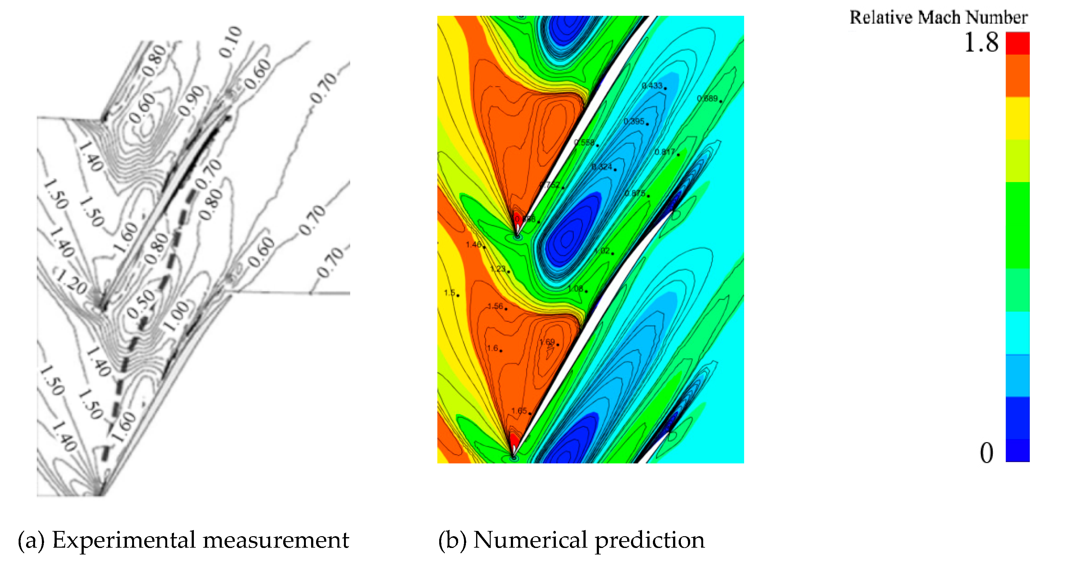
Figure 2.
Spanwise distributions of outlet elemental performance parameters under the near-stall condition.
Figure 2.
Spanwise distributions of outlet elemental performance parameters under the near-stall condition.
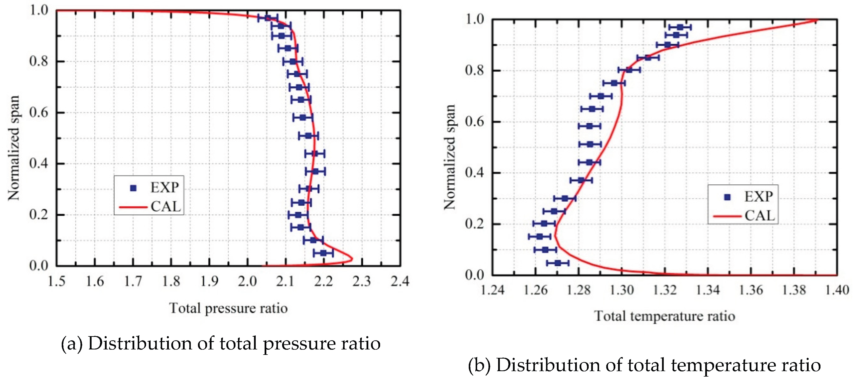
Figure 3.
Relative positions of blade-tip clearances.
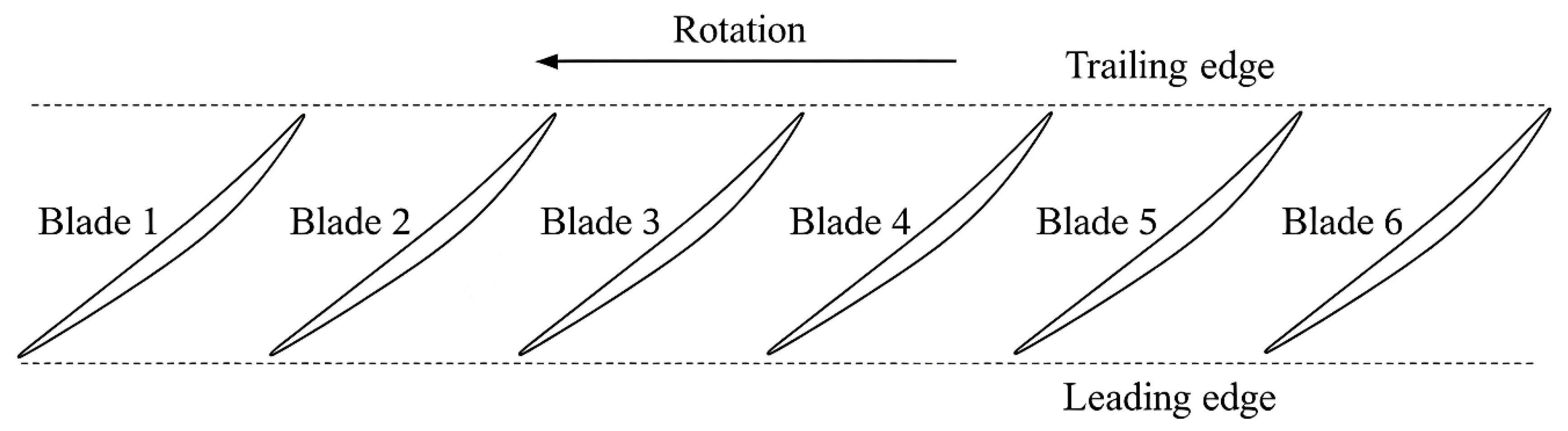
Figure 4.
Overall compressor performance at an average tip clearance of 0.75τ.
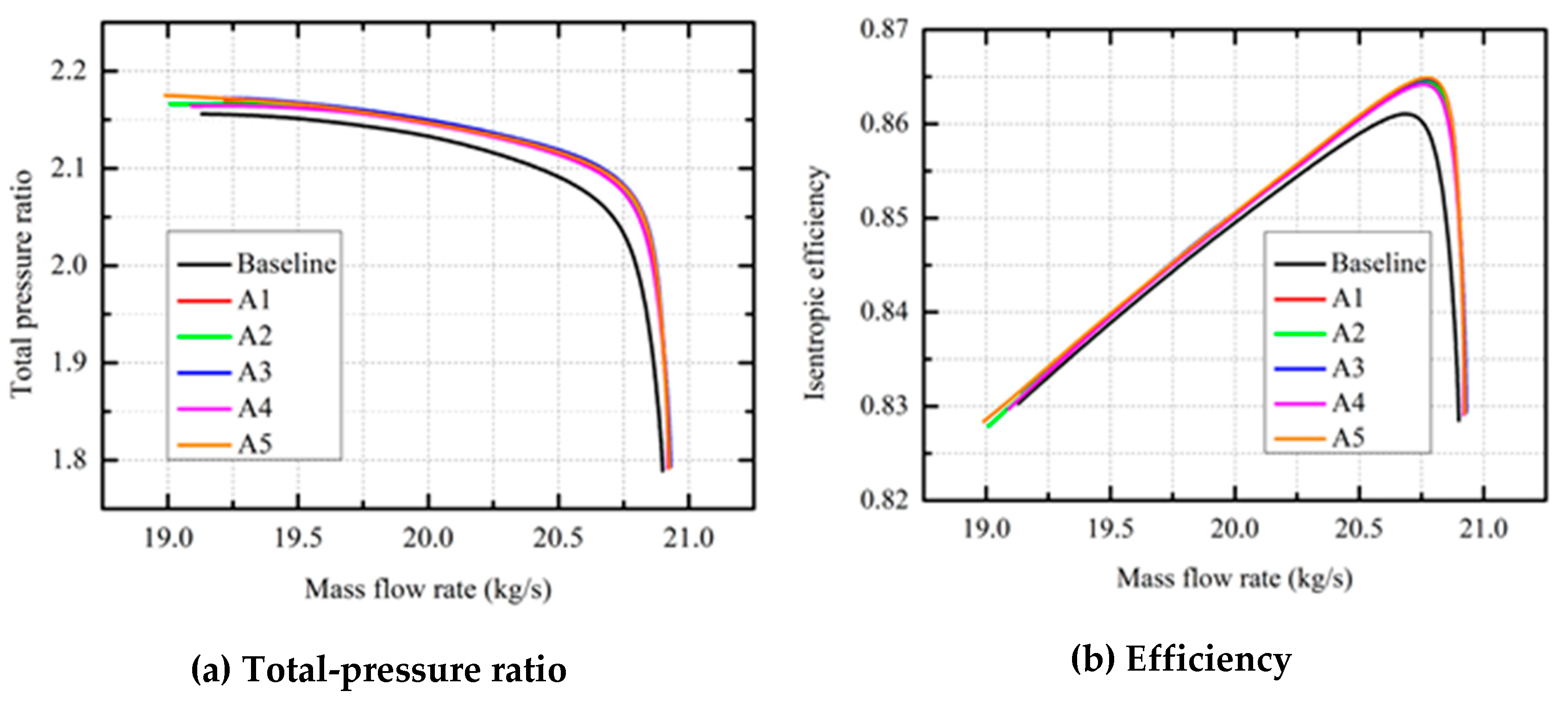
Figure 5.
Overall compressor performance at an average tip clearance of 1.25τ.
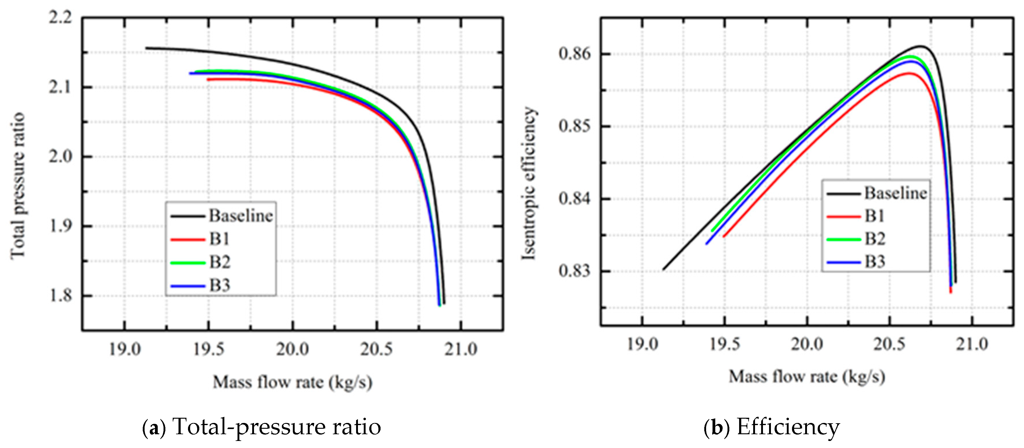
Figure 6.
Overall performance of the compressor with mixed non-uniform clearances.
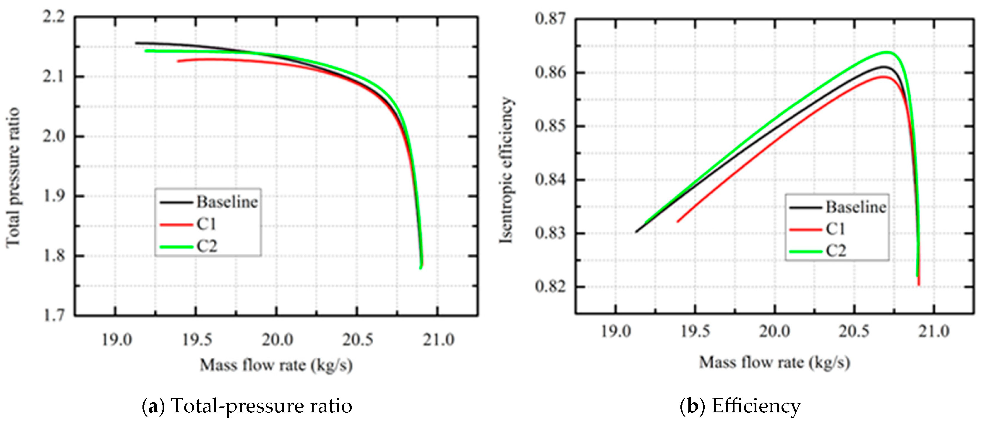
Figure 7.
Spanwise distribution of compressor exit isentropic efficiency and its locally enlarged views.
Figure 7.
Spanwise distribution of compressor exit isentropic efficiency and its locally enlarged views.
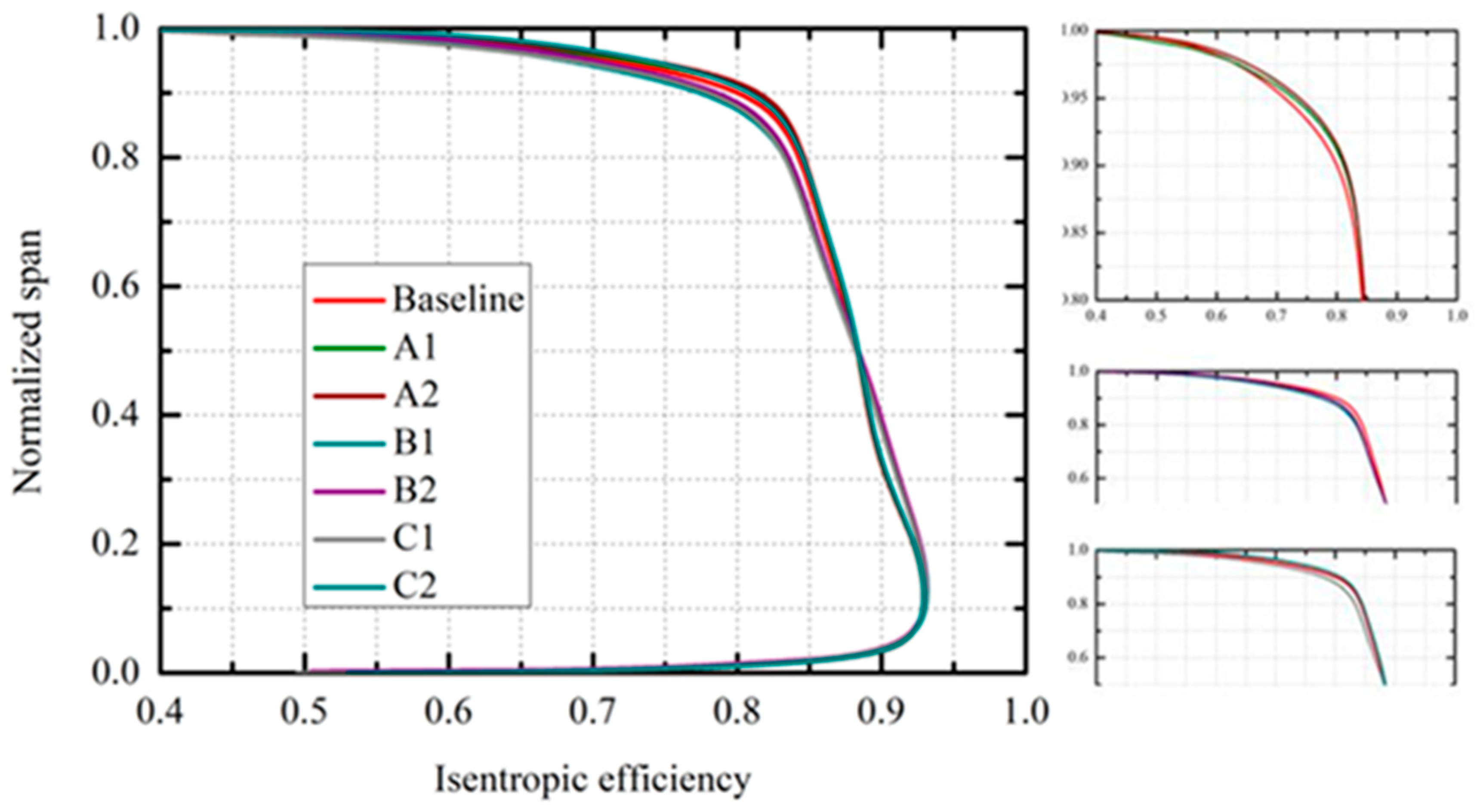
Figure 8.
Relative Mach number distributions in the compressor passage at peak efficiency condition under different clearance distributions.
Figure 8.
Relative Mach number distributions in the compressor passage at peak efficiency condition under different clearance distributions.
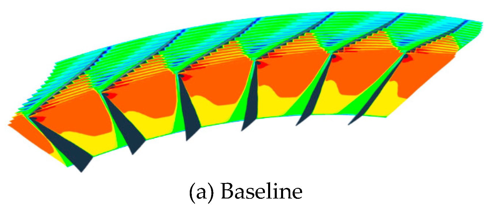
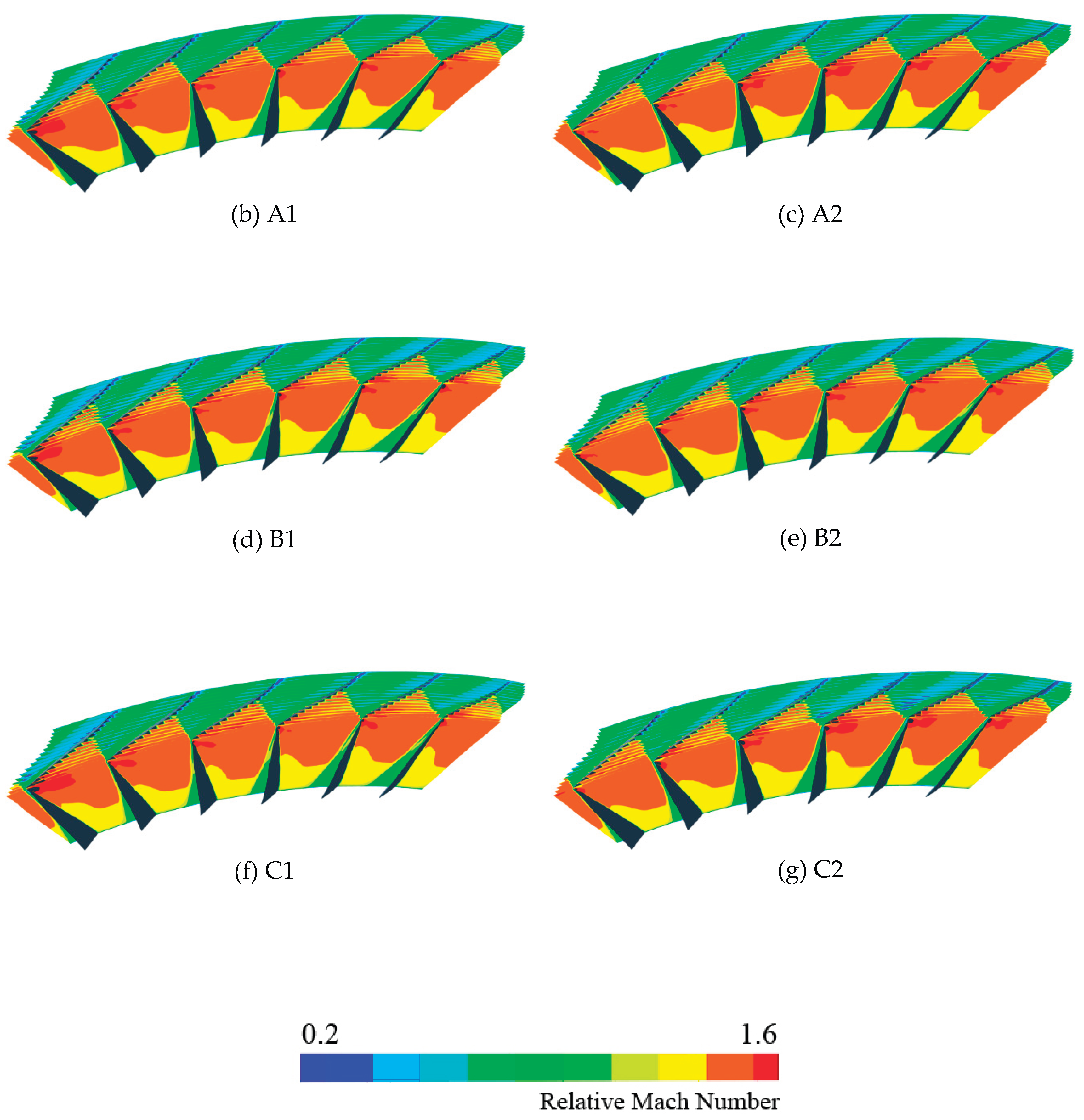
Figure 9.
Tip leakage flow distributions of the compressor at peak efficiencycondition under different clearance distributions.
Figure 9.
Tip leakage flow distributions of the compressor at peak efficiencycondition under different clearance distributions.
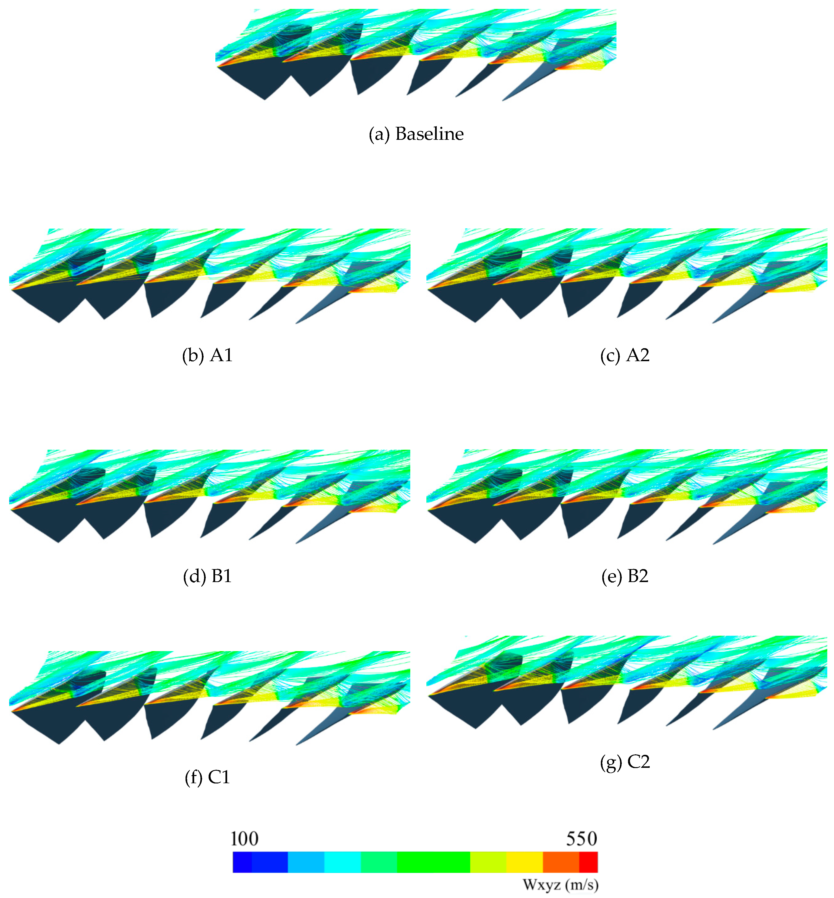
Figure 10.
Circumferential distribution of tip leakage flow momentum of the compressor at peak efficiency condition under different clearance distributions.
Figure 10.
Circumferential distribution of tip leakage flow momentum of the compressor at peak efficiency condition under different clearance distributions.
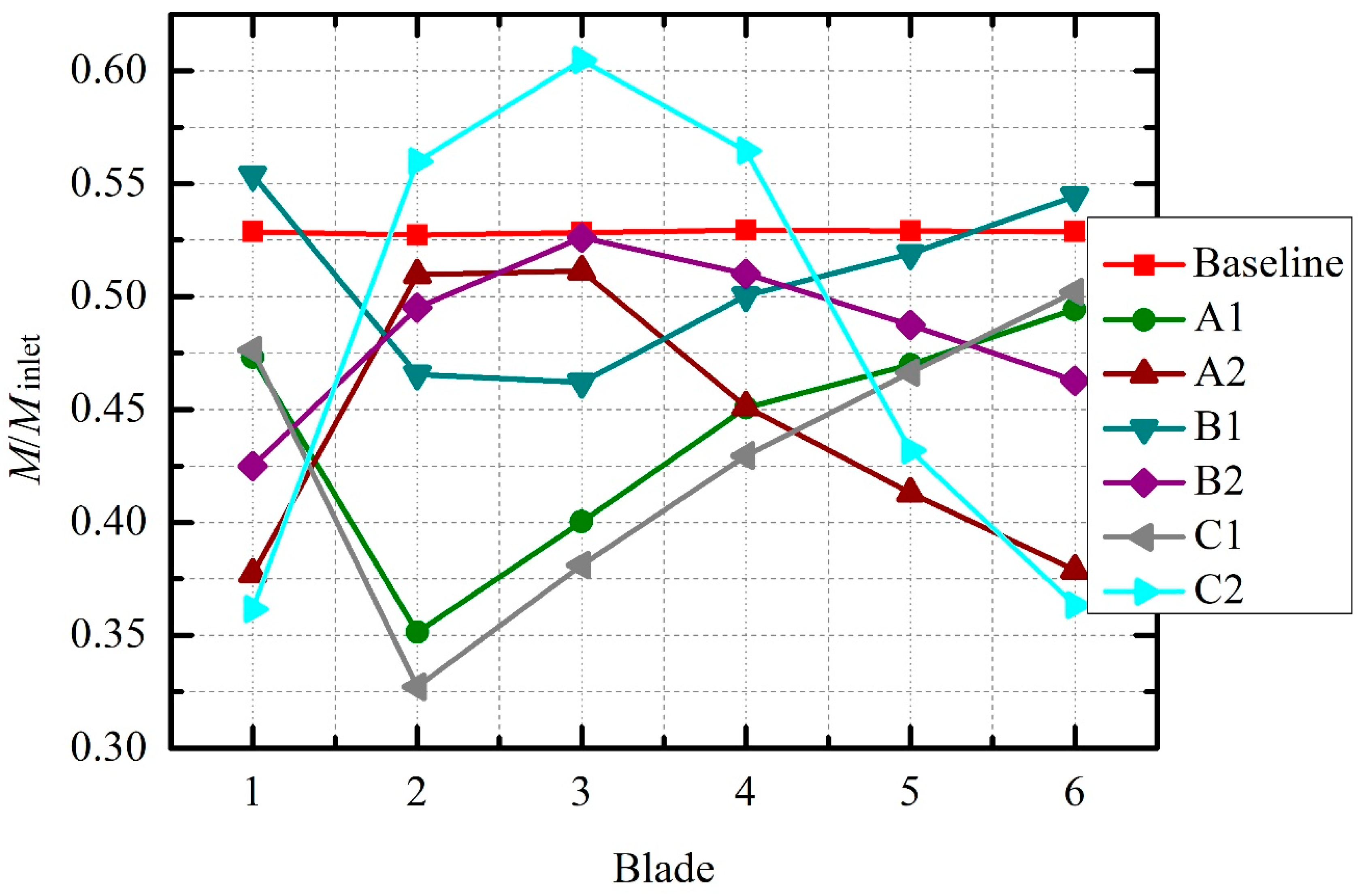
Figure 11.
Chordwise distribution of tip leakage flow momentum of the compressor at peak efficiency condition under different clearance distributions.
Figure 11.
Chordwise distribution of tip leakage flow momentum of the compressor at peak efficiency condition under different clearance distributions.
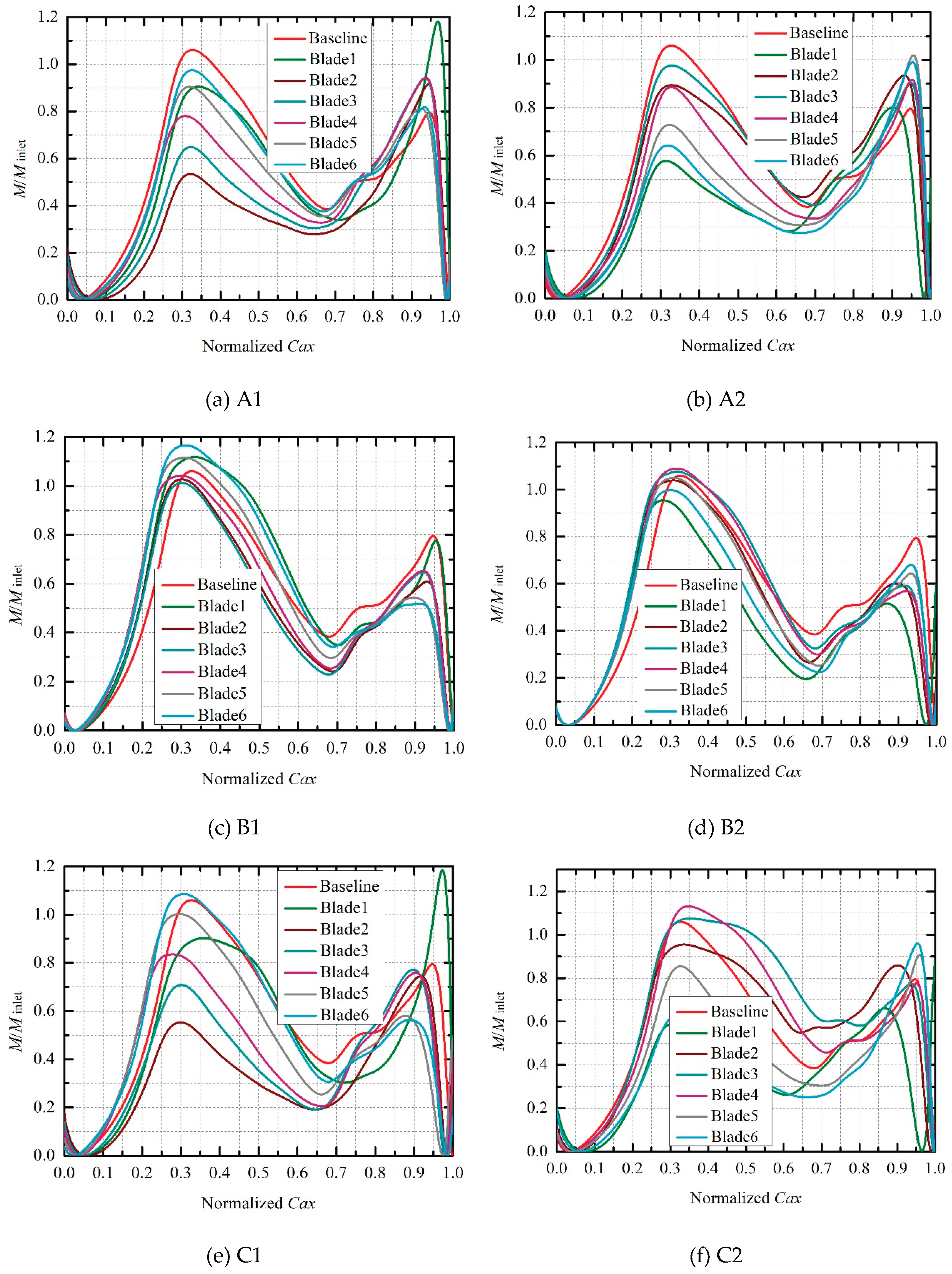
Figure 12.
Loss distributions in the compressor passage at peak efficiency condition under different clearance distributions.
Figure 12.
Loss distributions in the compressor passage at peak efficiency condition under different clearance distributions.
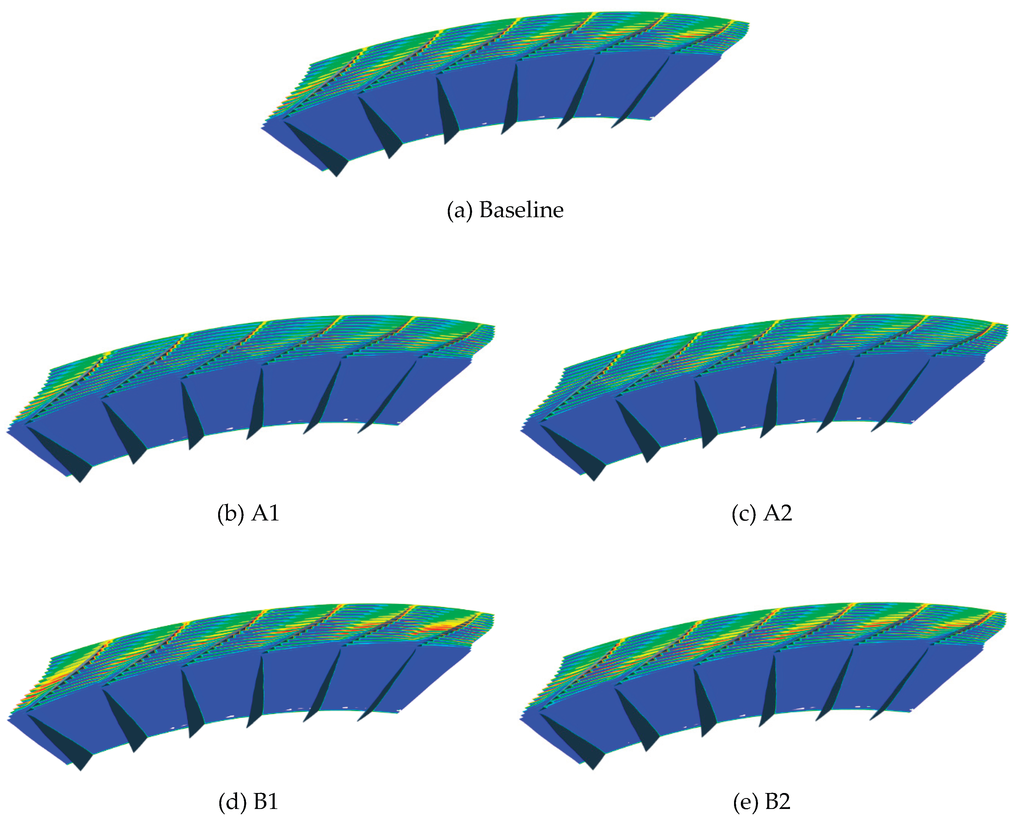
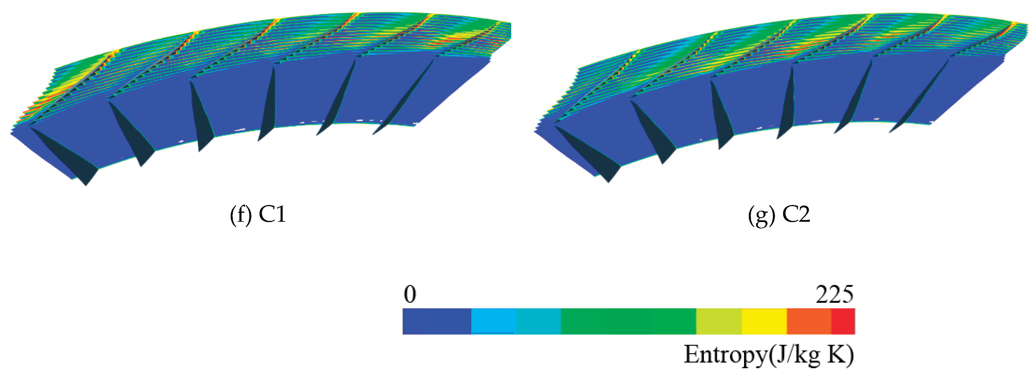

Table 1.
Circumferential non-uniform clearance distributions.
| No. | Blade1 | Blade2 | Blade3 | Blade4 | Blade5 | Blade6 | Average clearance |
| A1 | 0.5τ | 0.6τ | 0.7τ | 0.8τ | 0.9τ | 1.0τ | 0.75τ |
| A2 | 1.0τ | 0.9τ | 0.8τ | 0.7τ | 0.6τ | 0.5τ | |
| A3 | 1.0τ | 0.5τ | 1.0τ | 0.5τ | 1.0τ | 0.5τ | |
| A4 | 1.0τ | 0.9τ | 0.7τ | 0.5τ | 0.7τ | 0.9τ | |
| A5 | 0.75τ | 0.75τ | 0.75τ | 0.75τ | 0.75τ | 0.75τ | |
| B1 | 1.0τ | 1.1τ | 1.2τ | 1.3τ | 1.4τ | 1.5τ | 1.25τ |
| B2 | 1.5τ | 1.4τ | 1.3τ | 1.2τ | 1.1τ | 1.0τ | |
| B3 | 1.25τ | 1.25τ | 1.25τ | 1.25τ | 1.25τ | 1.25τ | |
| C1 | 0.5τ | 0.7τ | 0.9τ | 1.1τ | 1.3τ | 1.5τ | 1.0τ |
| C2 | 1.5τ | 1.3τ | 1.1τ | 0.9τ | 0.7τ | 0.5τ |
Disclaimer/Publisher’s Note: The statements, opinions and data contained in all publications are solely those of the individual author(s) and contributor(s) and not of MDPI and/or the editor(s). MDPI and/or the editor(s) disclaim responsibility for any injury to people or property resulting from any ideas, methods, instructions or products referred to in the content. |
© 2026 by the authors. Licensee MDPI, Basel, Switzerland. This article is an open access article distributed under the terms and conditions of the Creative Commons Attribution (CC BY) license (http://creativecommons.org/licenses/by/4.0/).
Copyright: This open access article is published under a Creative Commons CC BY 4.0 license, which permit the free download, distribution, and reuse, provided that the author and preprint are cited in any reuse.