

Submitted:
29 September 2026
Posted:
01 October 2026
You are already at the latest version
Abstract
This paper reports the development and multi-dimensional experimental characterisation of post-consumer wood-based PLA (PCW-PLA) composite panels for prefabricated façade systems, presenting results across a panel design and four sequential assessment phases during early-stage development activities: design integration, manufacturing workability, acoustic characterisation, and mechanical performance. Two panel typologies were investigated: solid panels (5 mm, compression moulding) and honeycomb panels (9 mm total thickness: 2 mm face sheets with 5 mm hexagonal core, FDM additive manufacturing), benchmarked against conventional market-reference products across four prefabricated façade configurations. Phase 1 (design integration) confirmed thermal equivalence across all configurations (U = 0.35-0.158 W/m²·K per ISO 6946), within the gate criterion of ΔU ≤ 10%. Phase 2 (manufacturing workability) established that conventional on-site tools are incompatible with the material's hardness characteristics, constraining the product to off-site prefabrication, with CNC milling as the optimal route. Phase 3 revealed that the honeycomb panel achieves broadband sound absorption α = 0.40-0.55 at 1500-3500 Hz, qualitatively distinct from the solid configuration (α < 0.05 broadband). At façade system level, FS-W2W-01 achieves insertion loss 26-35 dB across 100-2000 Hz; FS-W2W-02 exhibits resonance instability at ~750 Hz and ~1200 Hz, hypothesised to originate from local mass-spring-mass coupling within the honeycomb stratigraphy, requiring acoustic design optimisation. Phase 4 characterised the honeycomb panel: bending strength fm,mean = 15.5 N/mm², modulus of elasticity E = 2640 N/mm², and internal bond ft,mean = 0.34 N/mm² (CoV ≈ 38%), with face/core interface bonding identified as the critical development parameter. The results confirm the technical feasibility of PCW-PLA composite panels for prefabricated façade applications at TRL 3–4, establishing thermal equivalence with market-reference systems, off-site CNC manufacturing as the only viable production pathway, and broadband acoustic absorption of the honeycomb geometry as the primary differentiating performance characteristic. Limitations inherent to the TRL 3–4 context – prototype material quantities, non-standard test configurations, and indicative mechanical results – are documented alongside phase outcomes and identified as development priorities for next-TRL advancement.
Keywords:
bio-based PLA composite
; post-consumer wood
; sound absorption
; insertion loss
; bending strength
; internal bond
; FDM additive manufacturing
; prefabricated façade
; acoustic validation
; mechanical performance
1. Introduction
The construction sector accounts for approximately 50% of global raw material consumption, nearly 40% of greenhouse gas emissions, and up to 35% of solid waste generation [1,2]. Integrating bio-based materials across the construction value chain has accordingly emerged as a focal objective within EU environmental policy, aimed at reducing carbon emissions throughout building lifespans while contributing to the reduction of pollution and resource consumption [3,4,5,6,7]. Beyond their environmental advantage, bio-based materials offer an opportunity to reimagine building products through the synergy of bio-economy and circular economy principles, with the potential to optimise industrial-scale production value chains [8,9]. Combining bio-based feedstocks with polymer matrices into novel bio-composite materials is a viable strategy to achieve the performance levels required for construction applications while retaining the sustainability benefits of renewable and secondary raw materials [10,11,12]. Natural fibre bio-composites, derived from wood, are demonstrating promising results in terms of strength, cost-effectiveness, and substitutability for conventional materials [13]; however, incorporating natural material systems into composite manufacturing introduces uncertainties in structural performance and fabrication parameters, and developing bio-composite building products requires a bottom-up approach that treats the material system as an integral component of design and evaluation, and this is particular relevant for building envelope demanding application context [14,15].
Building envelope functions as a multi-performance system simultaneously meeting thermal, acoustic, and mechanical requirements, ensuring indoor comfort and energy performance while integrating diverse technologies [16,17,18]. The current market benchmark for prefabricated façade systems—aluminium or wooden framing, glazed or opaque panels, mineral wool insulation—represents mature technology, and bio-based alternatives must demonstrate compliance with the same functional requirements [19,20]. The prefabrication process offers additional sustainability advantages such as off-site manufacturing reduces CO2 emissions, assembly time, and production waste while facilitating disassembly, maintenance, and product durability [21,22,23], but it imposes precise dimensional, processability, and supply chain requirements that bio-based panel products must satisfy to be viable within industrialised construction workflows [24,25,26].
In this scenario, advancing novel bio-based materials in early-stage development (TRL 3-4) toward large-scale integration in the built environment requires satisfying a broad set of interconnected prerequisites such as norms compliance compatibility, manufacturing processability, functional performance, and structural adequacy, whose simultaneous management within a single development programme demands the coordinated contribution of multiple disciplines and research capabilities, lab facilities, and overall coordination. This complexity is compounded for bio-based products incorporating secondary raw materials sourced from waste streams: beyond meeting the technical performance requirements of the target application, these materials must demonstrate performance capability under the constraints of early-stage supply chain immaturity, limited prototype availability, and the absence of dedicated normative frameworks governing their characterisation. For building envelope applications, where façade components must simultaneously satisfy thermal, acoustic, structural, and constructive requirements, the capacity to connect these dimensions within a coherent development programme is a prerequisite for credible industrial positioning and scale-up. This integrative capacity has been demonstrated at the level of bio-based façade system modules through design simulation and normative testing activities [14,15,27], and is formalised as a structured multi-dimensional methodology applicable to bio-based panels at early technology readiness stages in the companion framework paper [28].
Post-consumer wood-based polylactic acid (PCW-PLA) composite panels represent a specific instance of this broader challenge: a bio-based thermoplastic panel that valorises construction and demolition wood waste as secondary raw material [29,30,31]. The material presents characteristics that make single-dimension testing insufficient for development decisions: hardness significantly exceeding conventional wood-based panels [32,33].
The present paper extends this research line to a specific material system, post-consumer wood-based polylactic acid façade composite panels, which valorises construction and demolition wood waste through an upcycling process converting post-consumer wood into a bio-based thermoplastic panel [34] to coordinate PCW-PLA composite challenges that makes single-dimension testing insufficient for development decisions. The different characteristics interact in ways that determine industrial viability: a PCW-PLA panel that performs acoustically but cannot be processed at industrial scale, or that integrates thermally but fails structurally, is not a viable building product. To the best of the authors’ knowledge, no published experimental campaign characterises PCW-PLA composite panels across the presented four performance dimensions: (1) design integration, (2) manufacturing workability, (3) acoustic behaviour, and (4) mechanical performance, relevant to prefabricated façade applications validation during early-stage (TRL3-4) component development. The experimental programme follows the Panel Design stage and the sequential assessment described in [28]. Section 2 presents materials and methods; Section 3 reports results phase by phase with gate outcomes; Section 4 discusses four aspects of the characterisation findings; Section 5 states the principal conclusions.
2. Materials and Methods
2.1. Panel Typologies
Two PCW-PLA composite panel typologies were investigated. Solid panels (5 mm thickness; density: 1.24 g/cm3) were manufactured by compression moulding from a PLA matrix reinforced with lignin and lignocellulosic components derived from processed post-consumer wood. Honeycomb panels (9 mm total thickness: 2 mm face sheet + 5 mm hexagonal core + 2 mm face sheet; density: 1.14 g/cm3) were produced via FDM additive manufacturing using a hexagonal infill pattern. The honeycomb geometry was introduced as a design evolution of the solid typology, motivated by the hypothesis that internal cellular structure would enhance acoustic dissipation, a hypothesis addressed in Phase 3. Both typologies were produced within Wood to Wood project (W2W) project [34] by Bloom Renewable [35] within an international supply chain coordinated at material level by UPV/EHU [36] and at compound level by NTUA [37]. Prototype material quantities were limited by the early-stage supply chain, constituting a methodological constraint on sample sizes acknowledged throughout. Panel typologies (production process and panel type), panel geometry and the target façade stratigraphies (Section 2.3) constitute the Panel Design starting conditions of the framework [28]; the PCW-PLA compound is a fixed input.
2.2. Reference Products
Three market-reference products were selected as performance benchmarks: OSB3 (12 mm, not disclosed supplier), gypsum board (12.5 mm, not disclosed supplier), and cement board (12.5 mm, not disclosed supplier). A commercial injection-moulded PLA panel (5 mm, standard PLA without PCW reinforcement) was additionally included in Phase 3 acoustic characterisation exclusively as a market-available PLA baseline, not as a proposed construction material, to isolate the effect of PCW reinforcement and honeycomb geometry on acoustic behaviour relative to the parent polymer.
2.3. Façade Configurations
Prefabricated façade configurations were defined using market-reference products and PCW-PLA based panels. Steady-state thermal transmittance (U-value) was calculated per ISO 6946. Dynamic thermal parameters (time lag, decrement factor, and periodic thermal transmittance) and hygrothermal performance assessment (surface condensation risk) were calculated per EN ISO 13786:2017 [38] and UNI EN ISO 13788:2012 [39] respectively, using a certified online calculation tool, assigning λ = 0.13 W/m·K to the PCW-PLA panels.
2.4. Sequential Assessment Programme and Go/No-Go Logic
The characterisation programme follows the Panel Design stage and the four sequential phases described in [28]: (1) design integration, (2) manufacturing workability, (3) acoustic characterisation, and (4) mechanical performance. Each phase produces a gate outcome that determines whether the next phase proceeds and, critically, which panel typologies advance with gate outcomes are PROCEED, REDESIGN or DISCONTINUE [28]. The gate logic is established a priori: Phase 4 mechanical characterisation is conducted exclusively on typologies that have passed the Phase 3 acoustic performance gate. This constraint is both methodological, consistent with the sequential framework [28]—and practical: prototype material is insufficient to run mechanical tests on all typologies independently of acoustic outcome. The specific gate criteria and their rationale are defined in [28]; the present paper reports the outcomes against those criteria.
2.5. Test Methods
The testing methods are structured in 4 phases:
- Design integration (Phase 1): thermal transmittance per ISO 6946 [40]; fixing system compatibility by constructive verification against standard aluminium and wood subframe configurations.
- Manufacturing workability (Phase 2): four machining methods evaluated (electric jigsaw, water jet, pantograph vacuum router, CNC milling centre) on edge quality, dimensional accuracy, and industrial scalability rated on a 5-point Likert scale [41,42]; target tolerance ±2 mm. Workability assessment was conducted on the solid panel typology only. The honeycomb panel was produced by FDM additive manufacturing directly to the specimen dimensions required for each test phase (net-shape manufacturing); no post-production machining of FDM specimens was performed. Dimensional accuracy of FDM-produced specimens was verified prior to testing and found within the ±2 mm target tolerance. Workability of FDM panels in an industrial prefabrication context, including trimming, edge processing, and on-site or off-site cutting to final installation dimensions, was not assessed at this TRL 3-4 stage and is identified as a requirement for later-TRL characterisation.
- Acoustic characterisation (Phase 3): sound absorption coefficient α= 1 − |R|2 following ISO 10534-2 [43], impedance tube Ø40 mm and Ø100 mm, 100–5000 Hz, n = 3 samples per material. The impedance-tube absorption protocol (ISO 10534-2, two-microphone transfer-function method) follows the setup previously applied by the authors to additively manufactured cavity-based resonators [44] and used for the preliminary absorption characterisation of electrospun nanofibre membranes at the same DIN facility [45]. Insertion loss (IL = Lwithout − Lwith) per ISO 11691 [46] adapted for layered façade configurations at specimen scale by the DIN Laboratory, University of Bologna [47]—an adaptation appropriate for TRL 3–4 preliminary characterisation, with results acknowledged as indicative pending full-scale testing.
- Mechanical characterisation (Phase 4): bending strength and modulus of elasticity per EN 310:1993 [48] on 7 specimens (50 × 9 × 150 mm); internal bond per EN 319:1993 [49] on 8 specimens (50 × 50 mm2). EN 310 and EN 319 are adopted as the nearest applicable methodology, as no dedicated standards exist for FDM wood-PLA composite panels. Tests conducted at CUT [50] outside the scope of material accreditation. For both test types, the coefficient of variation (CoV = standard deviation/mean × 100%) is reported alongside mean values as an indicator of inter-specimen variability to be analyzed based on TRL 3-4 consistency of the manufacturing process and the uniformity of the face/core bonding interface across the prototype batch, so to be interpreted as a manufacturing maturity indicator rather than a material property metric and applied as Gate 4 criterion.
3. Results
3.1. Phase 1—Design Integration
Phase 1 established four façade configurations and validated their thermal performance through a two-level assessment: (i) the complete façade assembly, verifying regulatory compliance and design integration; and (ii) the core stratigraphy (panel–insulation–panel), establishing the thermal baseline for acoustic test specimens characterised by impedance tube in Phase 3.
The design process was oriented against two representative acoustic performance levels defined by commercial lightweight façade systems: FS-M-01 (Figure 1) is a gypsum-plasterboard double-leaf assembly targeting a sound reduction index Rw ≈ 64 dB [51,52]; FS-M-02 (Figure 2) is a timber-frame assembly with OSB facings targeting Rw ≈ 52 dB (ref. “Comfort Rock” [53]). Two bio-based configurations were designed to evaluate contrasting PCW-PLA panel architectures against these references: FS-W2W-01 (Figure 3), employing compression-moulded solid panels and adopting honeycomb in the only internal side, and FS-W2W-02 (Figure 4), employing FDM-printed honeycomb panels. These configurations define the bio-based design space against which the alternatives are evaluated.
A prerequisite for valid acoustic comparison across configurations is that the assemblies compared operate at near-equivalent thermal resistance, verifying that configurations are thermally near-equivalent to market-reference configurations within a ΔU ≤ 10% criterion consistent with the framework gate threshold. Indeed, considering the thermal compliance if thermal transmittance varies significantly between configurations, differences in acoustic insulation cannot be attributed unambiguously to panel architecture and stratigraphy and it is critical to be compared with the purpose to have near-equivalent thermal solution; they may instead reflect different insulation regimes. A ΔU ≤ 10% criterion—consistent with the framework gate threshold [28]—is applied. At full-façade level, this verifies that bio-based configurations are thermally equivalent to market references as integrated building systems. Thermal parameters were assessed in accordance with ISO 6946, EN ISO 13786 and EN ISO 13788. Results are reported in Table 1.
Comparing bio-based to market-reference configurations, FS-W2W-01 deviates by 6.3% from FS-M-01 and 9.6% from FS-M-02; FS-W2W-02 deviates by 3.7% from FS-M-02 and 11.4% from FS-M-01. The 11.4% deviation relative to FS-M-01 reflects a design constraint: FS-M-01 represents a high-performance acoustic reference (Rw ≈ 64 dB) whose stratigraphy was intentionally kept unmodified, without adding layers to achieve thermal parity with the bio-based configurations which would have altered the acoustic reference stratigraphy and its benchmark role. At this development stage, the relevant objective is to validate bio-based façade configurations at near-equivalent thermal resistance to established market references; each bio-based configuration remains within ΔU ≤ 10% of at least one market reference at both complete-façade and core level (FS-W2W-01 vs FS-M-01: 6.3% and 8.7%; FS-W2W-02 vs FS-M-02: 3.7% and 2.5%). All configurations satisfy the Italian regulatory limit for Zona Climatica E (U ≤ 0.23 W/m2K).
Rw values are system-level indicators characterising complete façade assemblies under diffuse field conditions (ISO 717-1) and they are introduced as design context to justify the selection of the reference stratigraphies and the acoustic ambition of the study. They do not constitute a direct benchmark for the insertion loss measurements reported in Section 3.3, which are conducted on isolated core specimens under different conditions and cannot be compared with Rw values of complete systems. To this end, core stratigraphies were defined for each configuration: FS-M-01-CORE employs gypsum plasterboard face sheets (12.5 mm) on a 160 mm mineral wool core (2×80 mm, λ = 0.035 W/mK); FS-M-02-CORE employs OSB face sheets (12 mm) on the same mineral wool core; FS-W2W-01-CORE employs PCW-PLA solid panel face sheets (5 mm) on a 160 mm wood fibre core (2×80 mm, λ = 0.038 W/mK); FS-W2W-02-CORE employs PCW-PLA honeycomb panel face sheets (9 mm) on the same wood fibre core. A thermal comparability analysis was conducted at the core stratigraphy level (panel + insulation + panel), verifying that the four acoustic test specimens operate within the same thermal resistance class (ΔU ≤ 10%), to ensure that any observed difference in acoustic performance reflects the panel and stratigraphy design rather than differences in the insulation regime. Results are in Table 2. The thermal equivalence is confirmed within ΔU ≤ 10% at both full-façade and core stratigraphy level, the framework gate 1 is passed and PCW-PLA panels move to Phase 2.
3.2. Phase 2—Manufacturing Workability
Four machining methods were evaluated on the solid PCW-PLA panel against three criteria: edge quality, dimensional accuracy, and industrial scalability, rated on a five-point Likert scale parametrized as follows: score 1 = dimensional deviation >5 mm; score 2 = deviation 2–5 mm; score 3 = deviation 1–2 mm; score 4 = deviation 0.2–1 mm; score 5 = deviation <0.2 mm [42]. Workability assessment was conducted on the solid panel typology only. The honeycomb panel was produced by FDM additive manufacturing directly to the specimen dimensions required for each test phase (net-shape manufacturing); no post-production machining of FDM specimens was performed. Dimensional accuracy of FDM-produced specimens was verified prior to testing and found within the ±2 mm target tolerance. Workability of FDM panels in an industrial prefabrication context, including trimming, edge processing, and on-site or off-site cutting to final installation dimensions, was not assessed at this TRL 3-4 stage and is identified as a requirement for later-TRL characterisation.

Table 3.
Workability assessment for PCW-PLA panels (5-point Likert scale [41,42]; 1 = not acceptable, 3 = adequate, 5 = excellent).
| Method | Equipment type | Edge quality | Dimensional accuracy | Industrial scalability |
|---|---|---|---|---|
| Electric jigsaw | On-site | 1- inadequate | 1- inadequate | 1- inadequate |
| Water jet cutting | Off-site | 5-excellent | 3-adequate | 3-adequate |
| Pantograph vacuum router | Off-site | 5-excellent | 3-adequate | 3-adequate |
| CNC milling centre | Off-site | 5-excellent | 5-excellent | 5-excellent |
On-site equipment (electric jigsaw) proved fundamentally incompatible with PCW-PLA processing. Panel hardness produced edge deviations of 5-8 mm (2.5-4× the ±2 mm tolerance target), extended processing time (~6 ± 3 min per 100 mm cut length, approximately six times the duration for conventional panel materials), rough surface finish, and blade tooth damage after 3-4 cuts. CNC milling achieved optimal performance across all three criteria, producing edge deviations <0.2 mm and consistent surface quality across the production batch. Water jet cutting and pantograph vacuum routing yielded excellent edge quality but intermediate dimensional accuracy and scalability, suitable for batch but not volume production.
The PCW-PLA solid panel workability is confirmed by three off-site methods satisfy the Gate 2 criterion; CNC milling achieves the highest scores across all descriptors. Gate 2 is passed and the assessment proceeds to Phase 3.
3.3. Phase 3—Acoustic Characterisation
3.3.1. Sound Absorption Coefficient (α)
Six panel materials were characterised for sound absorption coefficient α per ISO 10534-2 [43] using impedance tubes of Ø40 mm and Ø100 mm, covering the frequency range 100–5000 Hz: (a) gypsum board; (b) cement board; (c) OSB3; (d) a commercial injection-moulded PLA solid panel; (e) PCW-PLA solid panel; (f) PCW-PLA honeycomb panel. The commercial PLA solid panel (d) is not a construction material and was not included as a façade product candidate, but it was tested as a matrix baseline reference to isolate the acoustic behaviour of the PLA polymer in solid panel geometry and allow direct comparison with the PCW-PLA solid panel (e), thereby quantifying the contribution of post-consumer wood reinforcement relative to the parent material. Results for all six materials are shown in Figure 5.
Results (Figure 6) show that conventional reference panels exhibit resonance-driven absorption at discrete frequency bands: (a) cement board shows values generally below 0.20 up to 2000 Hz, with a progressive increase at higher frequencies reaching α > 0.80 in the 3500-4000 Hz range; (b) gypsum board presents pronounced peaks at approximately 1400 Hz and 2400 Hz (α > 0.50), with values below 0.20 outside these narrow bands; (c) OSB3 exhibits a similar pattern, reaching α ≈ 0.90 at the same resonance frequencies, with an otherwise irregular and low absorption profile across the spectrum. The commercial PLA solid panel and the PCW-PLA solid panel both exhibit near-negligible absorption across the full range (α < 0.05 at most frequencies). The commercial PLA result isolates the matrix contribution: solid PLA geometry produces no acoustically relevant absorption. The PCW-PLA solid panel shows comparable behaviour to the commercial PLA baseline, with a marginal increase above 4000 Hz; post-consumer wood reinforcement does not modify the acoustic behaviour of a solid panel geometry. The PCW-PLA honeycomb panel exhibits a qualitatively distinct profile: a first absorption peak at approximately 800-900 Hz (α ≈ 0.40), followed by sustained broadband absorption between 1500 Hz and 3500 Hz where α = 0.40-0.55, before gradually decreasing above 4000 Hz. In contrast to the narrow resonance peaks of (b) gypsum board and (c) OSB3, the honeycomb configuration produces distributed absorption across a broad mid-frequency band, attributable to air cavity resonance and viscous dissipation within the hexagonal cellular core. It is important to highlight here that FDM print quality can modulate that resonant response [44], although this paper focuses on the multi-domain assessment of the four combinations rather than a parametric design analysis.
Based on these results and the gate criterion for this phase (α ≥ 0.30 across three contiguous one-third octave bands within 500-4000 Hz), PCW-PLA solid panel (α < 0.05 broadband) does not meet the criterion, while PCW-PLA honeycomb panel (α = 0.40-0.55 at 1500-3500 Hz) meets the criterion. For this reason, phase 4 mechanical validation proceeds exclusively on the honeycomb panel typology.
3.3.2. Insertion Loss (IL) of Façade Configurations
Insertion loss was characterised on the four core assemblies defined and thermally validated in Section 3.1 (see Table 2 and Figure 7). IL was measured following the DIN Laboratory adaptation of ISO 11691 [46] described in Section 2.5; results are shown in Figure 8. FS-M-01 and FS-M-02 deliver consistent IL performance: 29–36 dB and 30–36 dB respectively, increasing progressively with frequency, consistent with mass law behaviour combined with the dissipative contribution of mineral wool insulation.
FS-W2W-01 achieves IL = 26-35 dB across 100–2000 Hz. Performance is lower than market-reference systems at low frequencies (100–400 Hz: 26–28 dB), reflecting the reduced areal mass of 5 mm PCW-PLA face sheets (density 1.24 g/cm3) relative to 12–12.5 mm mineral-based panels. Above 1500 Hz, FS-W2W-01 approaches market-reference performance (34–35 dB), consistent with progressive mass law behaviour.
FS-W2W-02 exhibits a markedly different profile: peaks of 34–44 dB at 100–400 Hz are followed by pronounced drops to IL ≈ 15–20 dB at approximately 750 Hz and 1200 Hz. The dip at ~750 Hz is consistent with a local mass-spring-mass resonance of the honeycomb panel: in which the two 2 mm face sheets act as masses and the 5 mm air-filled hexagonal core as the compliant spring. For a symmetric double-leaf element with equal face-sheet areal masses m″, the resonance frequency is:
where ρ0 and c0 are the density and speed of sound of air, d is the core depth, and the face-sheet areal mass is m″ = ρt (ρ = 1140 kg/m3, t = 0.002 m → m″ ≈ 2.28 kg/m2). Substituting d = 0.005 m gives f0 ≈ 790 Hz, consistent with the observed dip location. The secondary dip at ~1200 Hz is hypothesised to arise from a higher-order stratigraphy resonance mode of the 258 mm composite assembly; quantification requires variable-stratigraphy testing not available at the current TRL stage. Both effects produce frequency-selective IL degradation incompatible with uniform broadband sound insulation requirements. As the acoustic response of additively manufactured resonant elements has been shown to depend on printed cell geometry and process parameters [44], an acoustic design intervention—modified cell geometry, constrained layer damping, or resonance-decoupling insert—is required before FS-W2W-02 can advance to later-TRL system-level validation.
Insertion loss results for the four core configurations, while not subject to a formal gate criterion at this stage, provide the acoustic characterisation baseline for the iterative design cycle presented in Section 3.5.
3.4. Phase 4—Mechanical Characterisation
Testing was conducted exclusively on the PCW-PLA honeycomb panel (9 mm), per Gate 3 outcome.
3.4.1. Bending Strength and Modulus Of Elasticity (EN 310:1993)
Mechanical characterisation of the PCW-PLA honeycomb panel was conducted on a Zwick/Roell Z100 universal testing machine . As noted in Section 2.5, no dedicated standard exists for FDM-printed wood-PLA composite panels; EN 310:1993 was adopted as the nearest applicable methodology. At this early-stage TRL 3-4, the available prototype material quantity constrains the number of test specimens that can be prepared without depleting the characterisation sample pool. EN 310:1993 prescribes a minimum of 6 specimens per loading direction (longitudinal and transverse); given the directional uniformity of the hexagonal cell geometry, which provides structural regularity in-plane without preferential anisotropy, bi-directional testing was not applied at this stage, and 7 specimens in a single direction were agreed as appropriate for the preliminary characterisation objective. Specimens were prepared at nominal dimensions of 50×9×150 mm and conditioned at (20 ± 2)°C and (65 ± 5)% RH for 72 h before testing. Results are reported in Table 4.
The reference values are mean bending strength fm,mean = 15.5 N/mm2 (range 13.0-17.6) and mean modulus of elasticity Emean = 2640 N/mm2 (range 2420-2894), with CoV ≈ 11% and ≈ 7%, respectively. Two failure modes were observed: face/core interface shear failure in 3 of 7 specimens, and flexural failure at or near mid-span in the remaining four specimens. The span-to-depth ratio of the test configuration (l/t ≈ 11; 150 mm specimen length, t = 9 mm) is lower than typically required to ensure bending-dominated failure at this panel thickness, promoting shear at the face/core interface. Consequently, the measured bending strength may underestimate the bending strength that would be obtained under bending-dominated conditions.
3.4.2. Internal Bond—Tensile Strength Perpendicular to Plane (EN 319:1993)
Internal bond was determined on a Zwick/Roell Z1455 universal testing machine. As with bending characterisation, EN 319:1993 was adopted as the nearest applicable methodology in the absence of a dedicated standard for FDM-printed wood-PLA panels (Section 2.5). The test purpose was to determine tensile strength perpendicular to the plane of the panel and corresponding failure modes. Eight square specimens of 50×50 mm2 were prepared and tested per EN 319:1993, consistent with the standard’s specimen count requirement and with the prototype material quantities available at this TRL stage. Specimens were conditioned at (20 ± 2)°C and (65 ± 5)% RH for 72 h before testing. Results are reported in Table 5.
Figure 9.
The relationship between load and deflection at mid-length according to (EN 310, 1993).
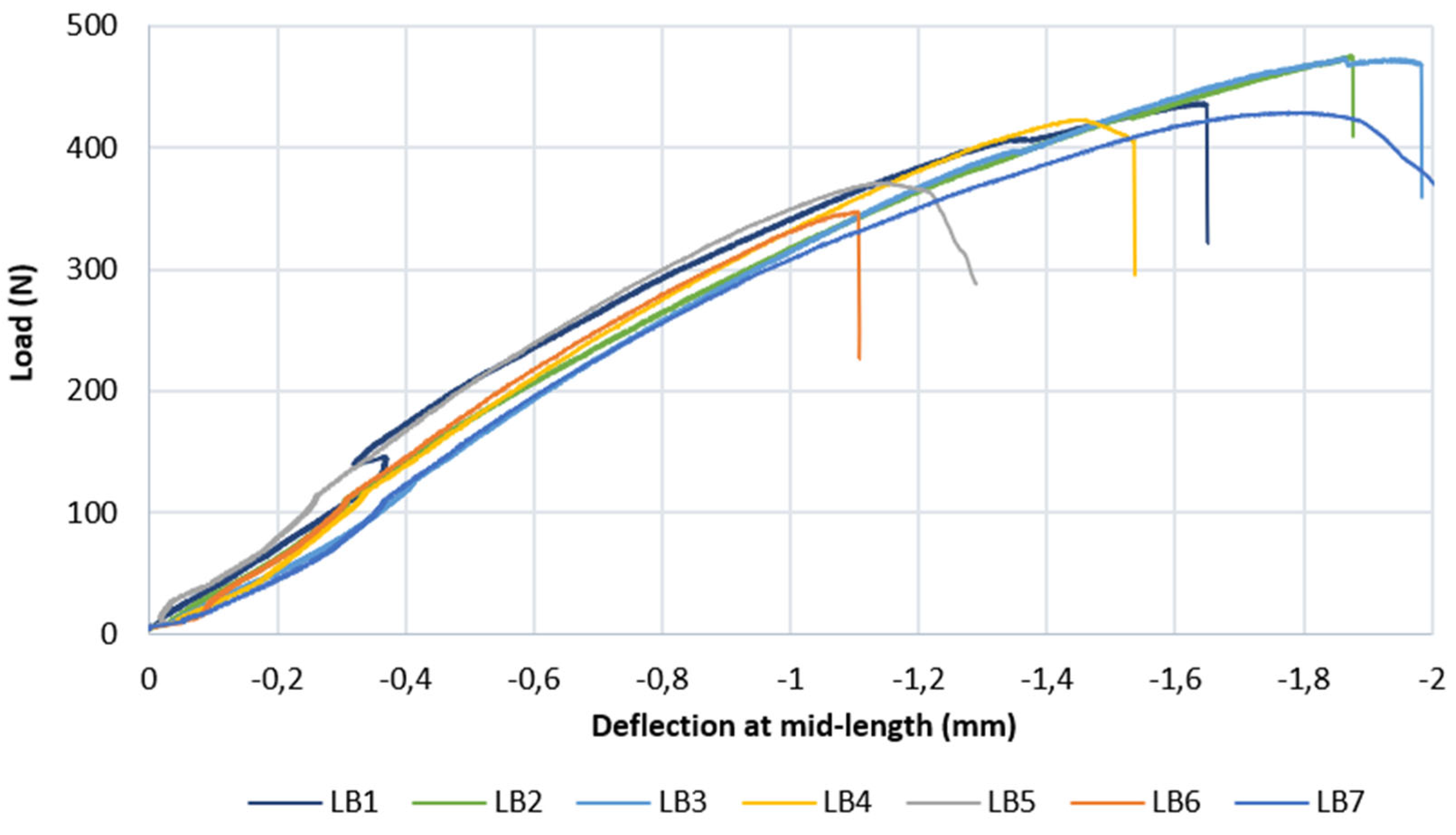
The reference values are mean tensile strength ft,mean = 0.34 N/mm2 (range 0.19-0.60; CoV ≈ 38%). Seven of eight specimens failed at the face/core interface; one failed through core tensile failure. The CoV is consistent with TRL 3-4 manufacturing maturity in which FDM process parameters (layer adhesion temperature, print speed, infill overlap) are not yet optimised for bonding consistency, as well as the process is not industrialized. Both bending and internal bond results converge on the face/core interface as the critical structural parameter.
3.4.3. Indicative Comparison with Market-Reference Requirements
To contextualise the mechanical results within the landscape of conventional façade panel products used as references in 3.1 and in 3.3, an indicative comparison is presented between the PCW-PLA honeycomb panel and the minimum mechanical requirements applicable to gypsum board, cement board, and OSB3 under their respective normative frameworks (EN 300, EN 12467, EN 520). This comparison is offered as a preliminary orientation for industrial positioning and as input to the Gate 4 assessment — it does not constitute equivalence testing. Several important limitations apply: specimen geometry and loading conditions differ between the standards applicable to each product category; the PCW-PLA honeycomb panel is characterised at 9 mm total thickness versus 12–12.5 mm for the reference products; and EN 310 and EN 319, adopted here as the nearest applicable methodology, are not the standards under which a certified façade panel would be tested. Results are therefore read as indicative of competitive positioning, with the gate assessment based on threshold (4) of [28].
Table 6.
Indicative mechanical performance comparison: PCW-PLA honeycomb panel vs. market-reference minimum requirements. * Converted from EN 520 breaking load (specimen 400 × 300 mm, span 350 mm, thickness 12.5 mm) using σ = 3PL/(2bh2). Different test standard—values indicative only. ** N.P.A. = No Performance Assessed/not declared in datasheet. *** Plasterboard core cohesion tested per EN 520 Clause 5.10, not directly comparable with EN 319.
Table 6.
Indicative mechanical performance comparison: PCW-PLA honeycomb panel vs. market-reference minimum requirements. * Converted from EN 520 breaking load (specimen 400 × 300 mm, span 350 mm, thickness 12.5 mm) using σ = 3PL/(2bh2). Different test standard—values indicative only. ** N.P.A. = No Performance Assessed/not declared in datasheet. *** Plasterboard core cohesion tested per EN 520 Clause 5.10, not directly comparable with EN 319.
| Property | PCW-PLA Honeycomb 9 mm |
OSB3 (EN 300) |
Cement board 12.5 mm (EN 12467, Cat. A2) |
Gypsum board 12.5 mm (EN 520, Type A) |
|---|---|---|---|---|
| fm (N/mm2) | 15.5 (13.0-17.6) | ≥22 (major)/≥11 (minor) | ≥5.0-8.1 | ≥6.2/≥2.4* |
| E (N/mm2) | 2640 (2420-2894) | ≥3500 (major)/≥1400 (minor) | N.P.A.** | N.P.A.** |
| ft (N/mm2) | 0.34 (0.19-0.60) | ≥0.34 | ≥0.65 | N/A*** |
The honeycomb panel bending strength exceeds the EN 300 minor-axis OSB3 requirement and substantially exceeds the indicative minimum for cement board and gypsum board, while remaining below the OSB3 major-axis value. Internal bond meets the OSB3 minimum at the mean level. Comparison is indicative only: specimen geometry, loading conditions, and the absence of a dedicated standard for FDM bio-composite panels preclude normative equivalence claims. Mean bending strength and modulus of elasticity are adequate for non-load-bearing cladding applications (rain-screen, decorative facing, non-load-bearing cladding under standard wind pressure and self-weight scenarios). Internal bond meets the minimum structural threshold at the mean level; the CoV ≈ 38% identifies FDM process parameter optimisation as the priority action before TRL 5 transition. The panel is not validated for structurally loaded façade applications.
The mechanical results position the PCW-PLA honeycomb panel as competitive with market-reference non-load-bearing cladding products across both bending and internal bond metrics, establishing the mechanical performance baseline required to return to Phase 1 design integration for final façade configuration development. Specifically, the Phase 3 IL diagnostic finding, resonance instability, resonance instability in FS-W2W-02 attributed to the 5 mm air-filled core (Section 3.3.2), identifies increased panel areal mass as the primary acoustic design corrective action. The Gate 4 mechanical baseline provides the structural reference against which redesigned configurations (modified core density, cell geometry, or damping layer) will be evaluated at the next design iteration before TRL 5 scale-up. Against threshold (4), f_m, E and f_t meet the thresholds at mean level, while the CoV of f_t (≈ 38%) exceeds 15%: Gate 4 issues REDESIGN, returning the configuration to Panel Design (FDM process parameters and panel stratigraphy) with subsequent re-entry at Phase 1 [28].
3.5. Iterative Design
The gate outcomes from Phases 2-4 collectively define the design space and acoustic-mechanical constraints for the next development iteration. The iterative design response targets the acoustic instability identified at system level while preserving the honeycomb geometry validated in Phase 3. The resonance dips of FS-W2W-02-CORE are attributed to local mass-spring-mass coupling within the honeycomb panel (estimated f0 ≈ 750-800 Hz at ~750 Hz) and to a higher-order stratigraphy resonance at ~1200 Hz. The design corrective action is the insertion of a 5 mm cork layer (ρ ≈ 410 kg/m3, λ ≈ 0.045 W/mK). The decision is to adopt this layer, not in direct attachment with the core and structural paprt of the façade, but with the external layers. This cork layer serves three concurrent acoustic functions: (i) it increases the total areal mass of the core assembly, shifting the mass-spring-mass resonance frequency downward and potentially outside the critical 500-2000 Hz range; (ii) it ensures material continuity at the panel/insulation interface, replacing the acoustically discontinuous contact between the air-filled honeycomb cells and the insulation surface with a dense, homogeneous layer; and (iii) it introduces additional acoustic damping through cork’s intrinsic viscoelastic dissipation properties. Cork was selected as a bio-based material compatible with the assembly bonding strategy and consistent with the bio-based positioning of the system.
The resulting configuration, designated FS-W2W-03 (Figure 10) which design a façade defining n.3 honeycomb variants (standalone honeycomb, honeycomb + cork, honeycomb + cork + UV and fire-protective coating (500 μm) based on the specific position and technical requirements to comply with. Phase 1 thermal validation of FS-W2W-03, conducted per the same methodology applied to all initial configurations (ISO 6946; EN ISO 13786; EN ISO 13788), confirms regulatory compliance for Zona Climatica E and absence of condensation risk; the additional cork layers marginally increase total thermal resistance relative to FS-W2W-02, maintaining U within the ≤10% ΔU criterion relative to FS-M-02. Acoustic experimental characterisation of FS-W2W-03 variants has not yet been conducted. FS-W2W-03 re-enters the framework at Phase 1 (completed) and proceeds through the remaining phases before advancing to Level 2 (TRL 5): Phase 2 dimensional verification of the laminated net-shape panel; Phase 3 re-characterisation of α and IL, as the panel stratigraphy has changed; and Phase 4 bending and internal bond tests, including the cork–panel interface, with FDM process parameters revised to reduce internal bond variability.
4. Discussion
The experimental results demonstrate the framework’s gate logic functioning as designed across all four phases. The critical decision point in the results was Gate 3: the solid PCW-PLA panel failed the absorption criterion, redirecting Phase 4 mechanical validation exclusively to the honeycomb typology. This outcome illustrates the principal efficiency gain of gate-controlled sequential validation at TRL 3-4: at this development stage, prototype material is produced in limited quantities from a multi-node international supply chain, and testing capacity at specialist laboratories is finite. Allocating mechanical testing to both panel typologies regardless of acoustic gate outcome would have consumed prototype material and testing time without advancing the primary development objective, identifying a panel configuration with both acoustic potential and structural adequacy. The gate structure converts sequential experimental results into resource allocation decisions, compressing the development timeline relative to parallel characterisation approaches. Gate 4 issued REDESIGN, returning the configuration to Panel Design and, from there, to Phase 1, generating FS-W2W-03 as a design response grounded in Phase 3 acoustic findings rather than in speculative geometry variation. The two-cycle iterative sequence (from initial characterisation through gate-directed redesign to thermal validation of revised configuration) constitutes the framework operating as intended: a structured development pathway from material characterisation to acoustically and mechanically validated panel configuration, progressing within the constraints of available material, testing infrastructure, and development stage.
In manufacturing phase 2, emerged pathway and supply chain implications. Gate 2 established that the PCW-PLA material’s hardness, significantly exceeding that of OSB, gypsum board, and cement board, is incompatible with standard on-site construction tools regardless of panel geometry. This constraint is material-intrinsic and therefore carries forward to FS-W2W-03 unchanged: the addition of a cork interlayer does not alter the machining requirement. The off-site manufacturing pathway defines a strategic market positioning parameter rather than a development limitation: the panel is suited to industrialised, BIM-coordinated design-to-fabrication workflows in which dimensional coordination is resolved before production and field modification is not required. This positioning is structurally aligned with the growth trajectory of prefabricated off-site construction. This industrialization perspective open also with the FS-W2W-03 variants (standalone honeycomb, honeycomb + cork, honeycomb + cork + UV and fire-protective coating (500 μm), to a differentiation of PCW-PLA honeycomb by surface treatment for protected, moderately exposed, and fully exposed application contexts, extending its positioning across the standard exposure classification range of prefabricated façade cladding products, allowing a single panel system to address multiple regulatory and environmental contexts without geometry reformulation.
To the authors’ knowledge, no previously published dataset characterises the sound absorption profile of PCW-PLA composite panels for building façade applications; the Phase 3 results are therefore interpreted in the absence of direct literature comparison. The principal acoustic finding is the qualitative distinction between panel geometries: the honeycomb configuration achieves sustained broadband absorption (α = 0.40-0.55 at 1500–3500 Hz) through air cavity resonance and viscous dissipation within the hexagonal core, while all solid-geometry panels—including both PCW-PLA solid and commercial PLA—remain below α = 0.05 across the full spectrum. This confirms that the acoustic behaviour is governed by panel geometry rather than by matrix composition or post-consumer wood reinforcement: the PCW-PLA solid and commercial PLA results are indistinguishable, while the honeycomb geometry produces a qualitatively different absorption profile. At core stratigraphy level, FS-W2W-01-CORE approaches market-reference IL performance at mid-to-high frequencies, with a deficit at low frequencies consistent with the lower areal mass of the 5 mm PCW-PLA face sheets relative to 12-12.5 mm mineral-based panels. FS-W2W-02-CORE exhibits resonance instability at ~750 Hz and ~1200 Hz, consistent with local mass-spring-mass coupling within the honeycomb geometry. It is important to note that insertion loss measured on isolated core specimens via impedance tube—indicative and early-stage—is not directly comparable to the weighted sound reduction index Rw of complete façade systems measured under diffuse field conditions per ISO 717-1. The Rw values of the market-reference stratigraphy classes introduced as design context represent system-level targets for complete assemblies; the core-level IL results demonstrate acoustic potential and identify design constraints, but do not predict complete system Rw. Certification-grade characterisation at system level is planned at TRL 5.
For what concerns mechanical performance, no published study characterising PCW-PLA composite panels per EN 310 and EN 319 for building façade applications has been identified; results are accordingly interpreted as first-of-kind at this TRL stage. Mean bending strength (fm,mean = 15.5 N/mm2) positions the honeycomb panel above the EN 300 minor-axis minimum for OSB3 (≥11 N/mm2) and substantially above gypsum and cement board minima, indicating mechanical competitiveness for non-load-bearing cladding under standard façade service loads. The conservative test configuration—short span-to-depth ratio promoting shear failure over pure bending—means that true bending strength is equal to or greater than the reported values; the mechanical evidence base is not overstated. Internal bond strength (ft,mean = 0.34 N/mm2) meets the OSB3 minimum at mean level; the coefficient of variation (CoV ≈ 38%) reflects the manufacturing maturity of the FDM process at TRL 3-4, where print parameters governing face/core layer adhesion are not yet optimised. The dominance of interface tensile and interface shear failure modes across both test types consistently identifies the face/core bonding interface as the structural priority for TRL 5 development. Process parameter optimisation such as layer adhesion temperature, print speed, infill overlap at the face/core transition, is the targeted corrective action; material reformulation is not indicated by the failure mode evidence.
Finally for the iterative design rationale, the design changes of FS-W2W-03 is directly driven by the Phase 3 IL findings: the resonance instability of FS-W2W-02-CORE at ~750 Hz and ~1200 Hz requires an acoustic corrective action that increases areal mass, provides material continuity at the panel/insulation interface, and introduces additional damping without abandoning the honeycomb geometry confirmed as acoustically promising by the absorption gate. The bio-based character of cork is additionally consistent with the system’s bio-based positioning. The three proposed FS-W2W-03 variants address the application-context differentiation required for commercial viability without altering the core acoustic or structural design: variants are differentiated by surface treatment only, preserving the panel geometry and bonding strategy validated in Phases 3-4 while extending the product’s exposure class range to meet regulatory requirements for protected, moderately exposed, and fully exposed façade applications.
5. Conclusions
The construction sector’s transition toward bio-based building products is constrained not only by material availability but by the absence of structured methodologies capable of advancing novel composites from laboratory characterisation to market-ready façade components within the resource constraints typical of research and early-stage development contexts. Certification pathways designed for mature, standardised materials do not accommodate the iterative, multi-property nature of composite panel development; the result is a structural gap between material innovation and product-level validation.
This paper proposed and applied a gate-controlled, multi-phase validation framework to a PCW-PLA composite panel system, with the objective of demonstrating that acoustically, mechanically, and thermally comparable performance to market-reference configurations can be achieved and progressively refined within a transparent, reproducible sequence of go/no-go decisions. The framework’s second objective was methodological: to show that gate logic, when applied at the level of individual performance criteria, functions as a resource allocation mechanism, directing experimental effort toward configurations with demonstrated potential and generating iterative design feedback from test evidence rather than from speculative geometry variation.
Both objectives were met. The validation sequence confirmed that a bio-based panel system can achieve thermal equivalence with market-reference stratigraphy, identify a geometry-specific acoustic response, meet the Gate 4 mechanical thresholds at mean level, with internal bond variability as redesign target, and produce a next-generation configuration grounded in experimental findings, all within a single, coherent development cycle. The framework’s gate logic operated as designed: early-phase outcomes constrained and redirected later-phase scope, and the Gate 4 REDESIGN outcome produced a thermally validated design response to Phase 3 acoustic limitations, advancing the system from initial characterisation to a testable next configuration without requiring full parallel characterisation of all variants.
The contribution of this work to the bio-based product development literature is therefore twofold: a first-of-its-kind multi-dimensional characterisation dataset for PCW-PLA composite panels in a façade application context, and a transferable methodological structure, adaptable in phase content and gate criteria to other bio-based composite systems, that bridges the current gap between material-level research and product-level development. Accelerating the transition of bio-based innovations from laboratory to construction practice requires not only better materials but better development frameworks; the validated gate logic proposed here is intended as a contribution to that second need.
Author Contributions
Conceptualisation, A.P.; methodology, A.P.; experimental investigation, acoustic: G.F. and M.Ga.; experimental investigation, mechanical: Ł.H., P.K. and A.N.M.; experimental investigation, design integration and workability: A.P. and M.Gi.; data curation, A.P., G.F. and A.N.M.; writing — original draft, A.P.; writing — review and editing, all authors; supervision, A.P.; project administration, A.P.; funding acquisition, A.P. All authors have read and agreed to the published version of the manuscript.
Funding
This research was conducted within the Wood2Wood (W2W) project, funded by the European Union under the Horizon Europe programme, Grant Agreement No. 101138789. Mechanical testing was conducted within the MEZeroE project, funded by the European Union under the Horizon 2020 programme, Grant Agreement No. 953157. The views and opinions expressed are those of the authors only and do not necessarily reflect those of the European Union. Neither the European Union nor the granting authority can be held responsible for them.
Data Availability Statement
The data presented in this study are available on request from the corresponding author.
Acknowledgments
During the preparation of this study, the authors used Claude (Anthropic; Claude Sonnet 4.6 and Claude Opus 5.5) for the purposes of literature search support and editing and proofreading support, and GPT (OpenAI, GPT-Image-1) to enhance the resolution of a low-quality photograph (Figure 7) for readability only. The authors have reviewed and edited the output and take full responsibility for the content of this publication.
Conflicts of Interest
The authors declare that the research was conducted in the absence of any commercial or financial relationships that could be construed as a potential conflict of interest. The funders had no role in the design of the study; in the collection, analyses, or interpretation of data; in the writing of the manuscript; or in the decision to publish the results. All findings, interpretations, and recommendations represent the authors’ independent scientific judgment.
References
- Environment, U.N. Global Status Report for Buildings and Construction 2025-2026 | UNEP - UN Environment Programme. Available online: https://www.unep.org/resources/report/global-status-report-buildings-and-construction-2025-2026 (accessed on 31 August 2026).
- Buildings and Construction - Internal Market, Industry, Entrepreneurship and SMEs. Available online: https://single-market-economy.ec.europa.eu/industry/sustainability/buildings-and-construction_en (accessed on 31 August 2026).
- A European Green Deal. Available online: https://commission.europa.eu/strategy-and-policy/priorities-2019-2024/european-green-deal_en (accessed on 16 June 2023).
- Chen, L.; Zhang, Y.; Chen, Z.; Dong, Y.; Jiang, Y.; Hua, J.; Liu, Y.; Osman, A.I.; Farghali, M.; Huang, L.; et al. Biomaterials Technology and Policies in the Building Sector: A Review. Environ. Chem. Lett. 2024, 22, 715–750. [Google Scholar] [CrossRef]
- Calculation Framework for New Building Life-Cycle Global Warming Potential - European Commission. Available online: https://energy.ec.europa.eu/news/calculation-framework-new-building-life-cycle-global-warming-potential-2026-05-04_en (accessed on 31 August 2026).
- Bio-Based Products and Processes - Research and Innovation. Available online: https://research-and-innovation.ec.europa.eu/research-area/environment/bioeconomy/bio-based-products-and-processes_en (accessed on 31 August 2026).
- CBE JU: Supporting EU Policies through Bio-Based Solutions | Circular Bio-Based Europe Joint Undertaking (CBE JU). Available online: https://www.cbe.europa.eu/cbe-ju-supporting-eu-policies-through-bio-based-solutions (accessed on 31 August 2026).
- Circular Bio-Economy—Paradigm for the Future: Systematic Review of Scientific Journal Publications from 2015 to 2021 | Circular Economy and Sustainability | Springer Nature Link. Available online: https://link.springer.com/article/10.1007/s43615-021-00084-3 (accessed on 31 August 2026).
- Pracucci, A.; Zaffagnini, T. Tendenze Innovative Del Costruire. In L’evoluzione e La Diffusione Della Circolarità Di Processo Nell’architettura Mediante Prodotti e Componenti Biobased; 2026. [Google Scholar]
- Renewable and Sustainable Biobased Materials: An Assessment on Biofibers, Biofilms, Biopolymers and Biocomposites - ScienceDirect. Available online: https://www.sciencedirect.com/science/article/abs/pii/S0959652620310258 (accessed on 31 August 2026).
- Jones, D.; Ormondroyd, G.O.; Curling, S.F.; Popescu, C.-M.; Popescu, M.-C. 2 - Chemical Compositions of Natural Fibres. In Advanced High Strength Natural Fibre Composites in Construction; Fan, M., Fu, F., Eds.; Woodhead Publishing, 2017; pp. 23–58. ISBN 978-0-08-100411-1. [Google Scholar]
- Galimshina, A.; Moustapha, M.; Hollberg, A.; Padey, P.; Lasvaux, S.; Sudret, B.; Habert, G. Bio-Based Materials as a Robust Solution for Building Renovation: A Case Study. Appl. Energy 2022, 316, 119102. [Google Scholar] [CrossRef]
- Leszczyszyn, E.; Heräjärvi, H.; Verkasalo, E.; Garcia-Jaca, J.; Araya-Letelier, G.; Lanvin, J.-D.; Bidzińska, G.; Augustyniak-Wysocka, D.; Kies, U.; Calvillo, A.; et al. The Future of Wood Construction: Opportunities and Barriers Based on Surveys in Europe and Chile. Sustainability 2022, 14, 4358. [Google Scholar] [CrossRef]
- Pracucci, A.; Vandi, L.; Morganti, L.; Fernández, A.G.; Diaz, M.N.; Muedra, A.N.; Győri, V.; Kouyoumji, J.-L.; Larraz, J.A. Design and Simulation for Technological Integration of Bio-Based Components in Façade System Modules 2024. [CrossRef]
- Vandi, L.; Navarro Muedra, A.; Larraz, J.A.; Escudero, S.L.D.A.; Pracucci, A.A. Testing Activities for Technological and Normative Validation of Bio-Based Components in Facade System Modules 2024. [CrossRef]
- Shan, R.; Junghans, L. Multi-Objective Optimization for High-Performance Building Facade Design: A Systematic Literature Review. Sustainability 2023, 15, 15596. [Google Scholar] [CrossRef]
- Giovanardi, M.; Baietta, A.; Belletti, F.; Magnani, S.; Casadei, O.; Pracucci, A. Exploiting the Value of Active and Multifunctional Façade Technology through the IoT and AI. Appl. Sci. 2024, 14, 1145. [Google Scholar] [CrossRef]
- Soudian, S.; Berardi, U. Development of a Performance-Based Design Framework for Multifunctional Climate-Responsive Façades. Energy Build. 2021, 231, 110589. [Google Scholar] [CrossRef]
- Jones, D.; Brischke, C. (Eds.) Front Matter. In Performance of Bio-based Building Materials; Woodhead Publishing, 2017; pp. i–iii. ISBN 978-0-08-100982-6. [Google Scholar]
- Sandak, A.; Sandak, J.; Brzezicki, M.; Kutnar, A. Biomaterials for Building Skins. In Bio-based Building Skin; Sandak, A., Sandak, J., Brzezicki, M., Kutnar, A., Eds.; Springer: Singapore, 2019; pp. 27–64. ISBN 978-981-13-3747-5. [Google Scholar]
- Atsonios, I.; Katsigiannis, E.; Koklas, A.; Kolaitis, D.; Founti, M.; Mouzakis, C.; Tsoutis, C.; Adamovský, D.; Colom, J.; Philippen, D.; et al. Off-Site Prefabricated Hybrid Façade Systems: A Holistic Assessment. J. Facade Des. Eng. 2023, 11, 097–122. [Google Scholar] [CrossRef]
- Tam, V.W.Y.; Hao, J.J.L. Prefabrication as a Mean of Minimizing Construction Waste on Site. Int. J. Constr. Manag. 2014, 14, 113–121. [Google Scholar] [CrossRef]
- Fernando, D.; Navaratnam, S.; Rajeev, P.; Sanjayan, J. Study of Technological Advancement and Challenges of Façade System for Sustainable Building: Current Design Practice. Sustainability 2023, 15, 14319. [Google Scholar] [CrossRef]
- Savoja, G. Experimentation of Composites Materials Reinforced with Vegetable Fibres for the Construction Sector. TECHNE-J. Technol. Archit. Environ. 2018, 317–324. [Google Scholar] [CrossRef]
- EUR-Lex - 02010L0075-20240804 - EN - EUR-Lex. Available online: https://eur-lex.europa.eu/legal-content/EN/TXT/?uri=CELEX%3A02010L0075-20240804 (accessed on 31 August 2026).
- Circular Economy Principles for the Design of Buildings - EEB Response to Survey - EEB - The European Environmental Bureau
- Ioannou, O.; Konijnenberg, F. Valorizing Food Waste into Functional Bio-Composite Façade Cladding: A Circular Approach to Sustainable Construction Materials. Clean Technol. 2026, 8, 11. [Google Scholar] [CrossRef]
- Pracucci, A.; Giovanardi, M. A Multi-Dimensional Validation Framework for Post-Consumer Wood Reinforced PLA Panels in Prefabricated Façade Systems: Methodology and Assessment Structure at TRL 3–4 2026.
- Jahan, I.; Zhang, G.; Bhuiyan, M.; Navaratnam, S. Circular Economy of Construction and Demolition Wood Waste—A Theoretical Framework Approach. Sustainability 2022, 14, 10478. [Google Scholar] [CrossRef]
- Mrad, C.; Frölén Ribeiro, L. A Review of Europe’s Circular Economy in the Building Sector. Sustainability 2022, 14, 14211. [Google Scholar] [CrossRef]
- Barriers and Potentials for Circular Use of Waste Wood in Construction and Demolition Sector with Special Focus on Germany. Available online: https://www.mdpi.com/2413-8851/9/9/367 (accessed on 31 August 2026).
- Environment Friendly, Renewable and Sustainable Poly Lactic Acid (PLA) Based Natural Fiber Reinforced Composites – A Comprehensive Review - ScienceDirect. Available online: https://www.sciencedirect.com/science/article/abs/pii/S0959652621017029 (accessed on 31 August 2026).
- Polylactic Acid (PLA) Biocomposite: Processing, Additive Manufacturing and Advanced Applications. Available online: https://www.mdpi.com/2073-4360/13/8/1326 (accessed on 31 August 2026).
- Wood2wood-Project. Eu. Available online: https://www.wood2wood-project.eu/ (accessed on 14 April 2026).
- Bloom | Lignin, Hemicellulose and Cellulose-Based Materials. Available online: https://www.bloombiorenewables.com/ (accessed on 31 August 2026).
- University of the Basque Country. Available online: https://www.ehu.eus/en/en-home (accessed on 31 August 2026).
- Εργαστήριο Τεχνολογίας Πολυμερών ΕΜΠ. Available online: https://polymers.chemeng.ntua.gr/polymers.chemeng.ntua.gr (accessed on 31 August 2026).
- ISO 13786:2017; Thermal Performance of Building Components — Dynamic Thermal Characteristics — Calculation Methods. Available online: https://www.iso.org/standard/65711.html (accessed on 31 August 2026).
- ISO 13788:2012; Hygrothermal Performance of Building Components and Building Elements — Internal Surface Temperature to Avoid Critical Surface Humidity and Interstitial Condensation — Calculation Methods. Available online: https://www.iso.org/standard/51615.html (accessed on 31 August 2026).
- ISO 6946:2017; Building Components and Building Elements — Thermal Resistance and Thermal Transmittance — Calculation Methods. Available online: https://www.iso.org/standard/65708.html (accessed on 31 August 2026).
- Likert, R. A Technique for the Measurement of Attitudes. Arch. Psychol. 1932, 22, 1–55. [Google Scholar]
- Pracucci, A.; Giovanardi, M. Ecodesign Prioritization for BIPV Manufacturers Under ESPR Compliance: An LLM-Assisted Multi-Criteria Framework with Use Cases Application. Sustainability 2026. [Google Scholar] [CrossRef]
- ISO 10534-2:2023; Acoustics — Determination of Acoustic Properties in Impedance Tubes — Part 2: Two-Microphone Technique for Normal Sound Absorption Coefficient and Normal Surface Impedance. Available online: https://www.iso.org/standard/81294.html (accessed on 31 August 2026).
- Investigation of the Impact of Additive Manufacturing Techniques on the Acoustic Performance of a Coiled-up Resonator. The Journal of the Acoustical Society of America | AIP Publishing. Available online: https://pubs.aip.org/asa/jasa/article-abstract/153/5/2921/2891336/Investigation-of-the-impact-of-additive?redirectedFrom=fulltext (accessed on 25 September 2026).
- Nanofibers for Sound Absorption—A Preliminary Investigation - Manzi - 2025 - Macromolecular Symposia. Wiley Online Library. Available online: https://onlinelibrary.wiley.com/doi/10.1002/masy.70260 (accessed on 25 September 2026).
- ISO 11691:2020; Acoustics — Measurement of Insertion Loss of Ducted Silencers without Flow — Laboratory Survey Method. Available online: https://www.iso.org/standard/69859.html (accessed on 31 August 2026).
- UniBo - DIN. Available online: https://industrial-engineering.unibo.it/en (accessed on 31 August 2026).
- EN 310:1993 Wood-Based Panels Modulus of Elasticity and Bending. Available online: https://standards.iteh.ai/catalog/standards/cen/0bc47eac-778e-4f85-8f99-9d0b9fc36dc8/en-310-1993?srsltid=AfmBOoodfIZSVy3DjUUcbAErNOWCqdjqA-J9fA_lcxQ4t9-ndnzb3FhM (accessed on 31 August 2026).
- EN 319:1993 - Tensile Strength Test for Particleboards and Fibreboards. Available online: https://standards.iteh.ai/catalog/standards/cen/476c6e54-1b1a-491d-90a9-93da4e3601a5/en-319-1993?srsltid=AfmBOorOV9tJGsufAzeQXnc2r0-xO7s_ZGxwjGDembp0U5GcjUXEpw8W (accessed on 31 August 2026).
- Politechnika Krakowska Im. Tadeusza Kościuszki. Available online: https://www.pk.edu.pl/index.php?lang=en (accessed on 31 August 2026).
- Knauf Scheda Tecnica WM411C-75-6-S-001.It. Knauf Scheda Tecnica WM411C-75-6-S-001.
- Knauf Scheda Tecnica W628-EP-50-6-0-001.It. Knauf Scheda Tecnica W628-EP-50-6-0-001.
- MARLEGNO_brochure Case 2024 2024.
Figure 1.
Facade System—Market-01 (FS-M-01). The facade system adopts gypsum/cement boards products.
Figure 1.
Facade System—Market-01 (FS-M-01). The facade system adopts gypsum/cement boards products.
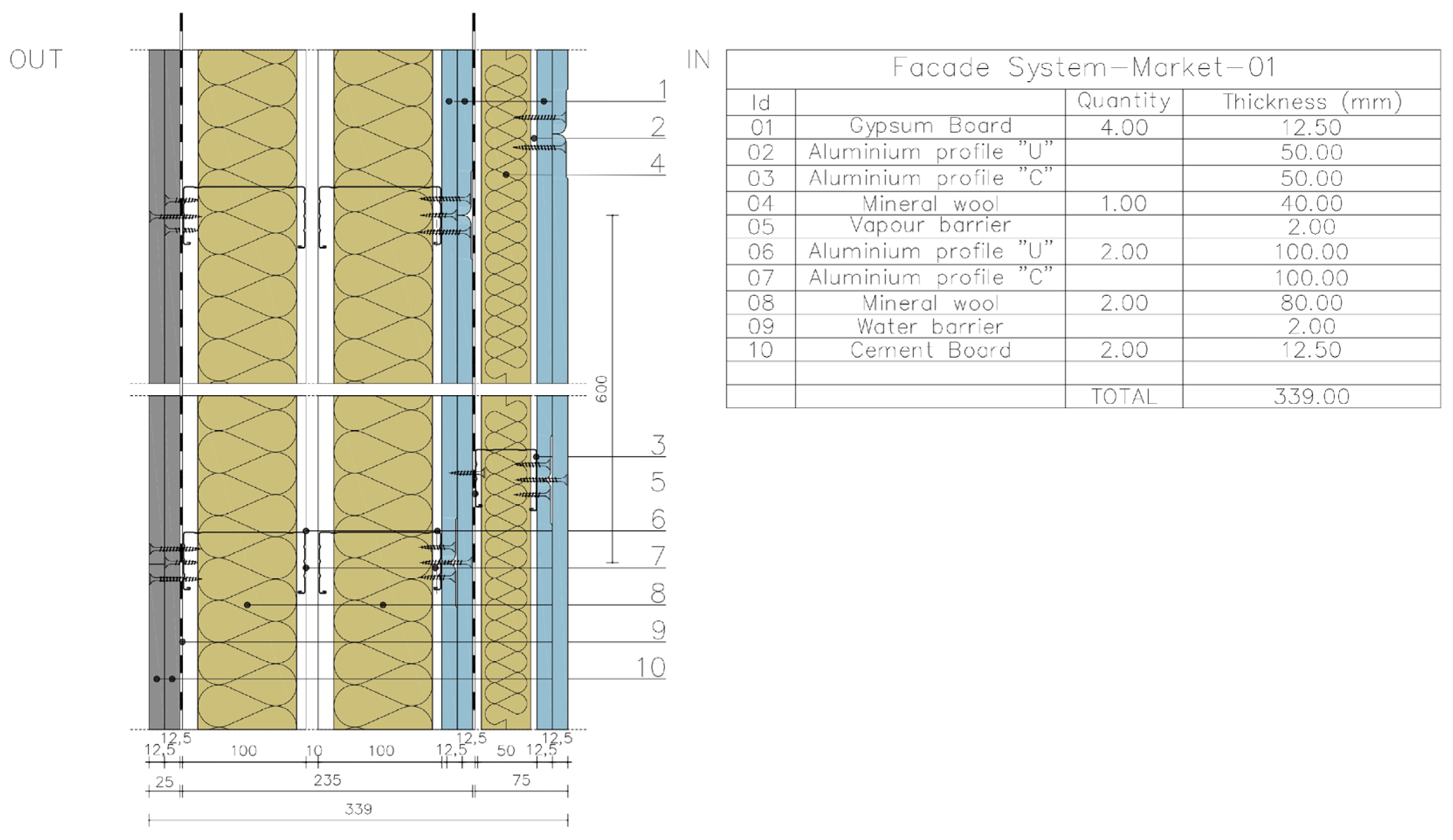
Figure 2.
Facade System—Market-02 (FS-M-02). The facade system adopts OSB2 products.
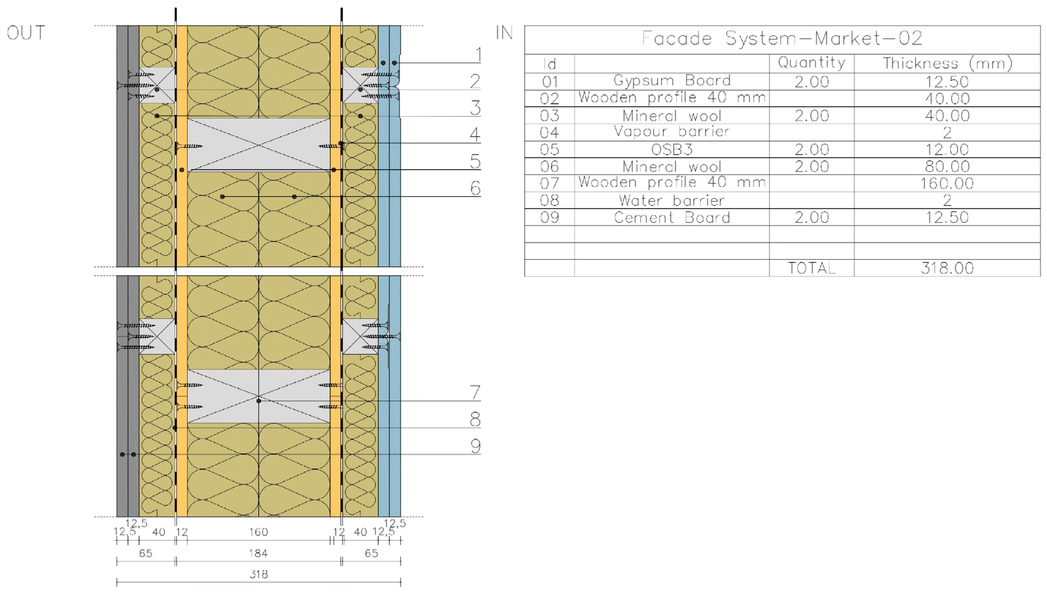
Figure 3.
FS-W2W-01 design integration. The facade system integrates PCW-PLA solid panels.
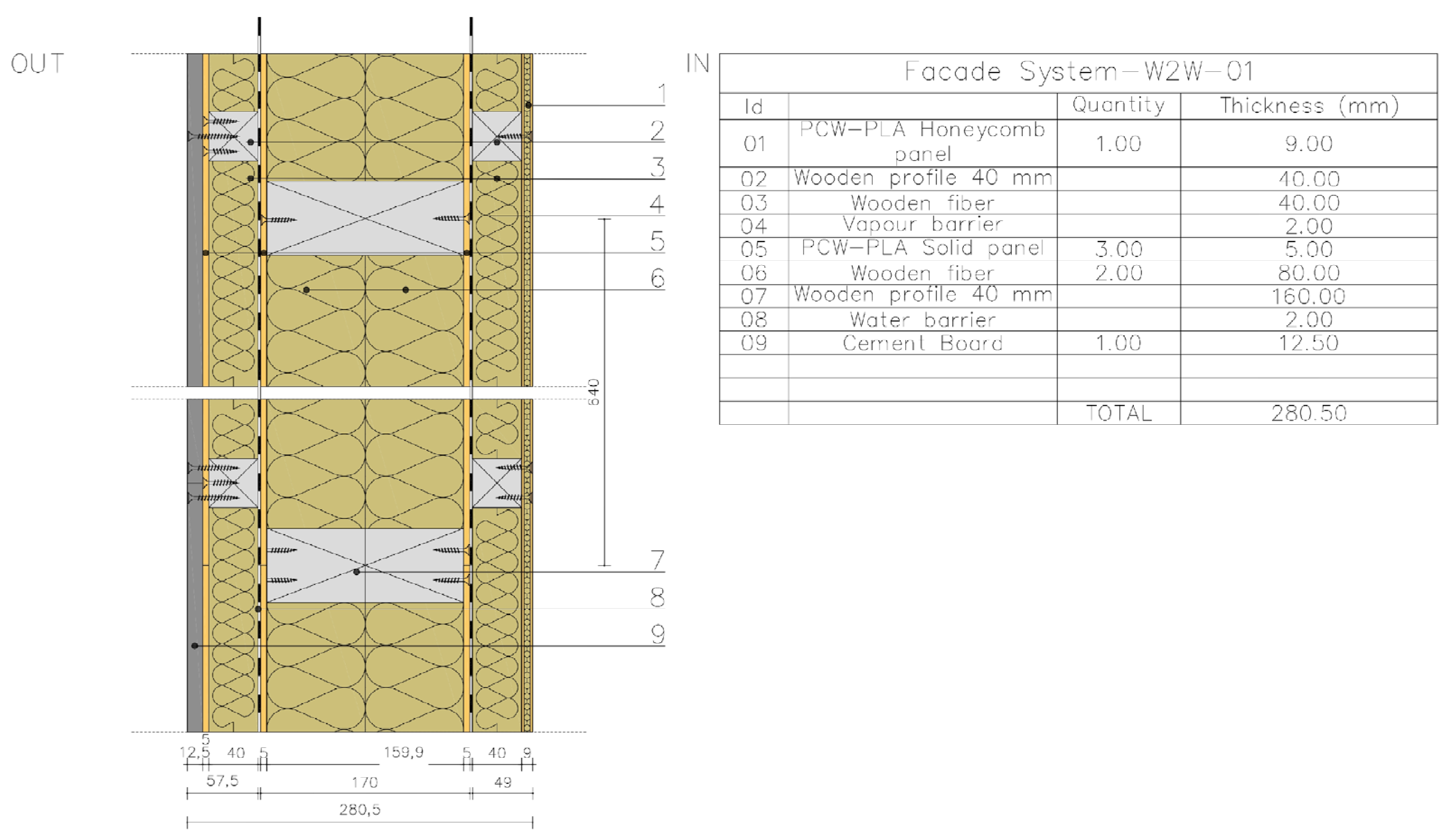
Figure 4.
FS-W2W-02 design integration. The facade system integrates exclusively PCW-PLA honeycomb panels.
Figure 4.
FS-W2W-02 design integration. The facade system integrates exclusively PCW-PLA honeycomb panels.
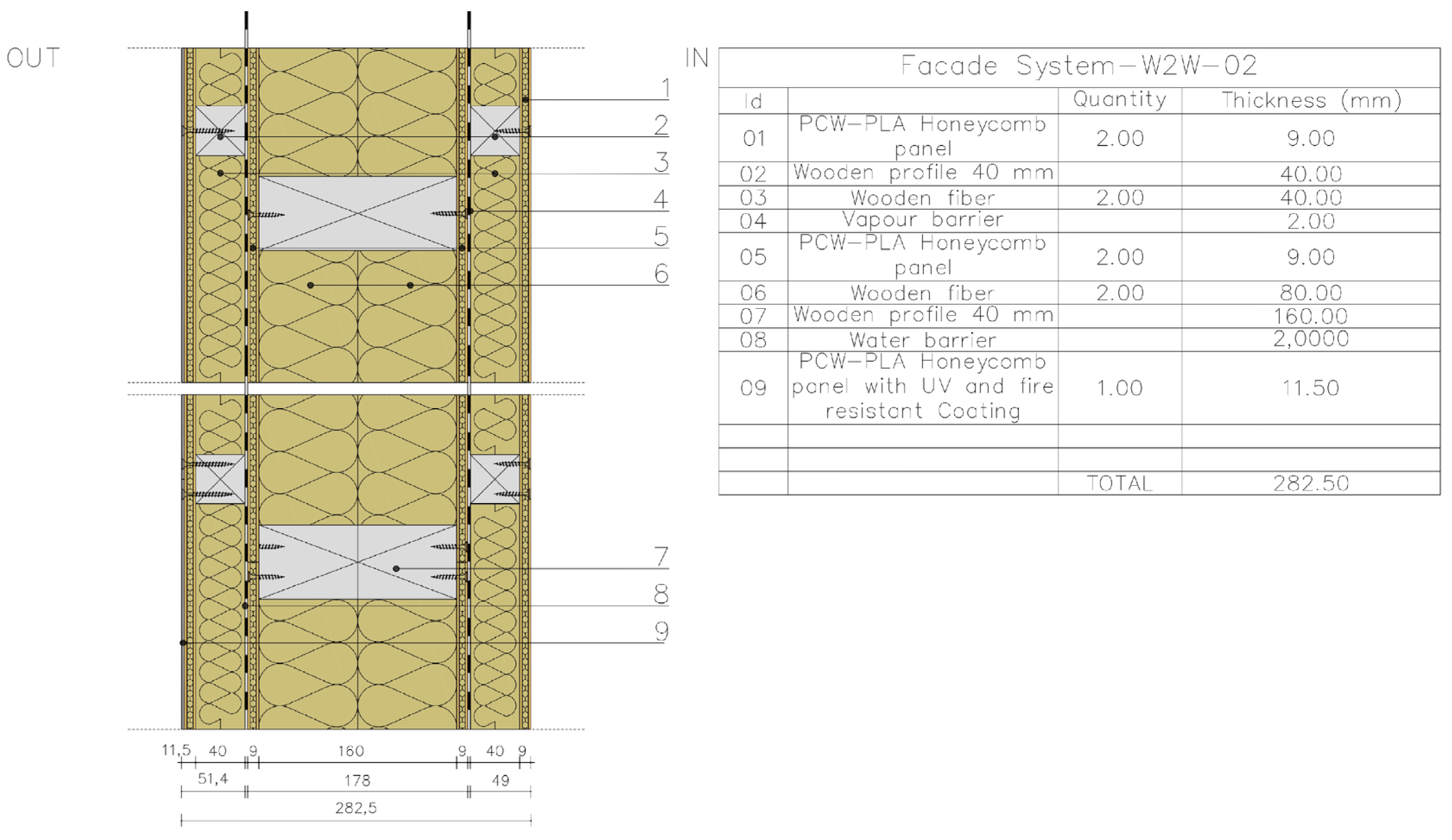
Figure 5.
Sampled for acoustic absorption test (10534-2): (a) gypsum board; (b) cement board; (c) OSB3; (d) commercial PLA solid panel; (e) PCW-PLA solid panel; (f) PCW-PLA honeycomb panel.
Figure 5.
Sampled for acoustic absorption test (10534-2): (a) gypsum board; (b) cement board; (c) OSB3; (d) commercial PLA solid panel; (e) PCW-PLA solid panel; (f) PCW-PLA honeycomb panel.
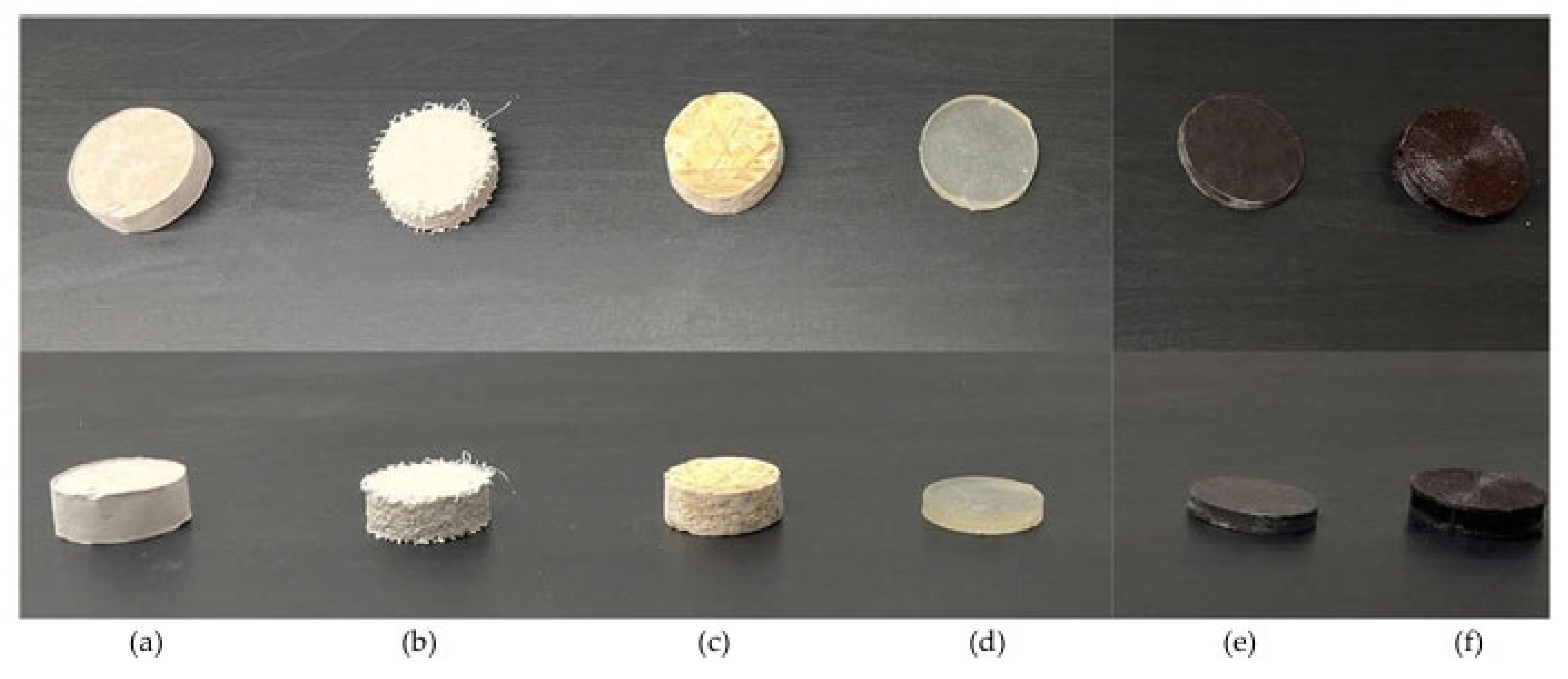
Figure 6.
Sound absorption coefficient (α) of (a) gypsum board; (b) cement board; (c) OSB3; (d) commercial PLA solid panel; (e) PCW-PLA solid panel; (f) PCW-PLA honeycomb panel.
Figure 6.
Sound absorption coefficient (α) of (a) gypsum board; (b) cement board; (c) OSB3; (d) commercial PLA solid panel; (e) PCW-PLA solid panel; (f) PCW-PLA honeycomb panel.
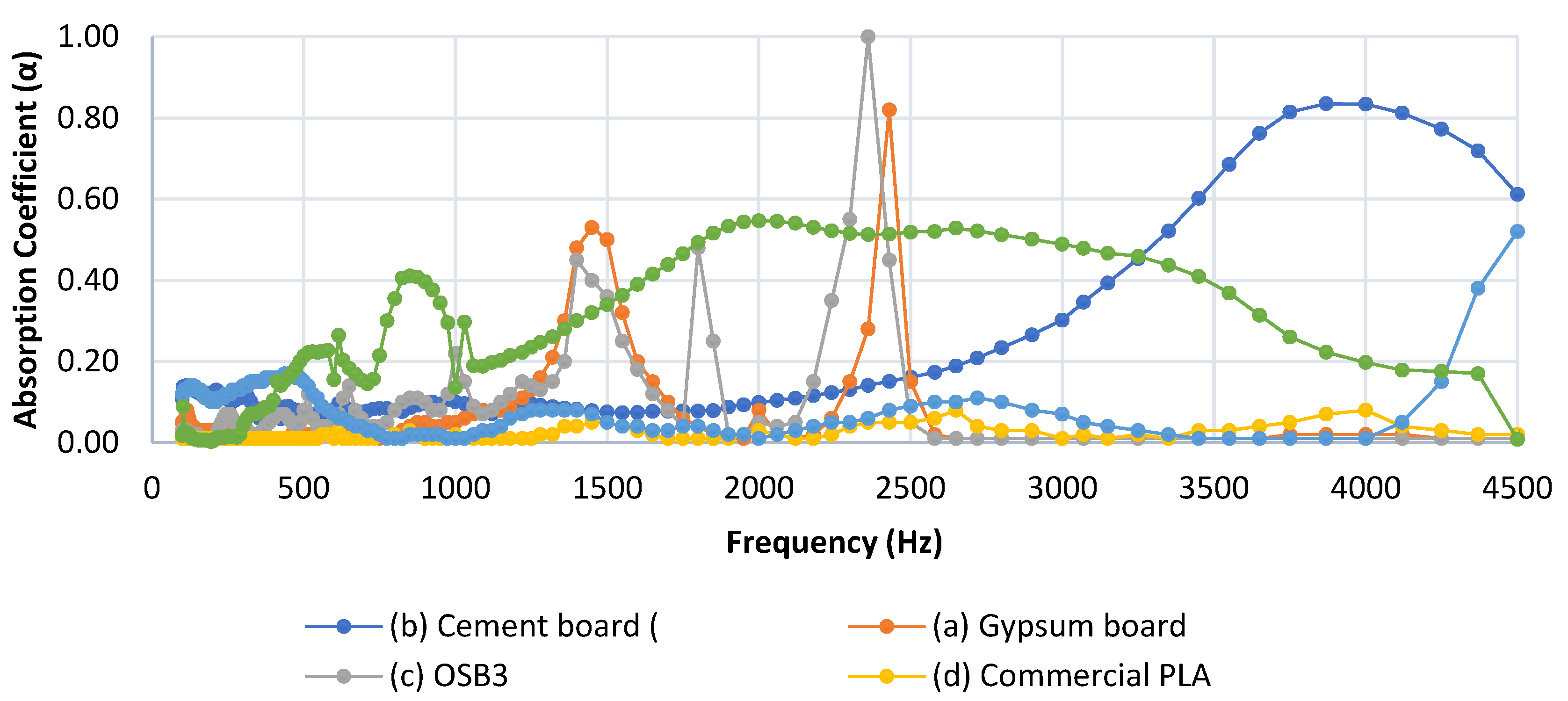
Figure 7.
Sampled Ø100 mm for insertion loss test (11691): (a) FS-M-01 CORE; (b) FS-M-02 CORE; (c) FS-W2W-01 CORE; (d) FS-W2W-02 CORE.
Figure 7.
Sampled Ø100 mm for insertion loss test (11691): (a) FS-M-01 CORE; (b) FS-M-02 CORE; (c) FS-W2W-01 CORE; (d) FS-W2W-02 CORE.

Figure 8.
Insertion loss (IL) of façade configurations samples for the “core” part as defined in 3.1.
Figure 8.
Insertion loss (IL) of façade configurations samples for the “core” part as defined in 3.1.
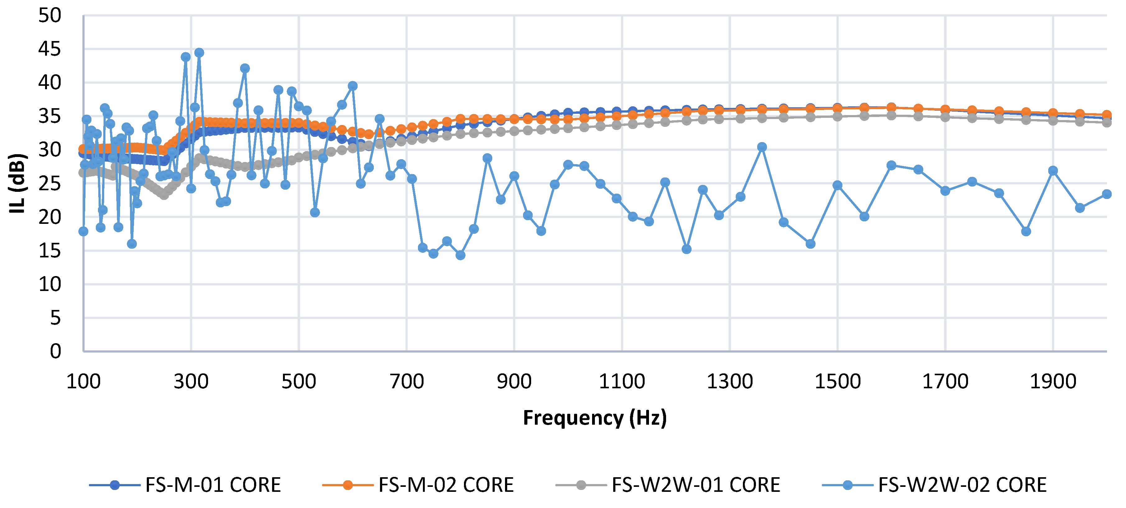
Figure 10.
Facade System—W2W-03 (FS-W2W-03) design after desing-testing activities. The facade system integrates W2W honeycomb panels in n.3 configurations defined after early stage testing actvities.
Figure 10.
Facade System—W2W-03 (FS-W2W-03) design after desing-testing activities. The facade system integrates W2W honeycomb panels in n.3 configurations defined after early stage testing actvities.
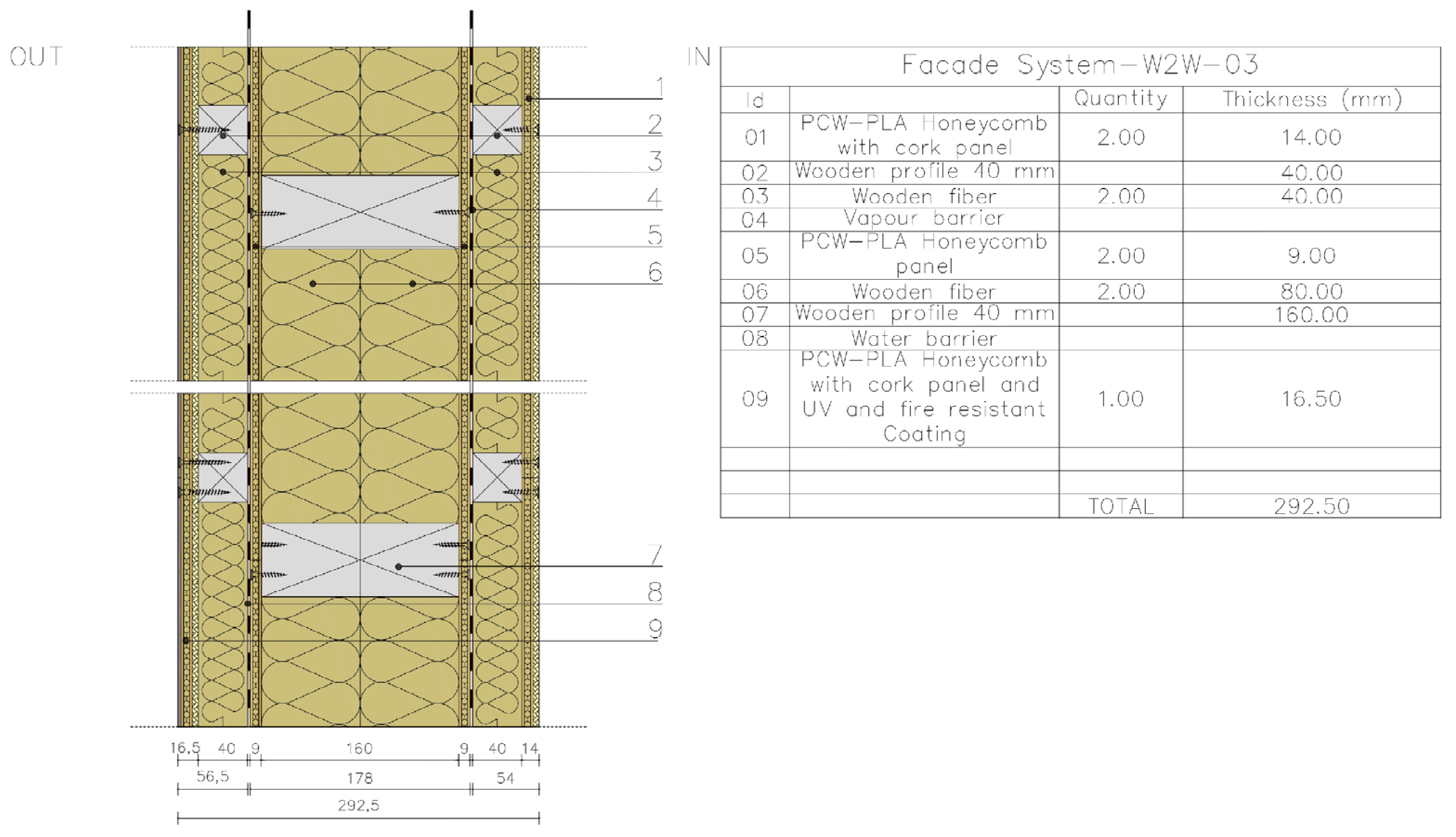
Table 1.
Façade configurations, steady-state thermal transmittance (ISO 6946), and dynamic thermal parameters (EN ISO 13786; hygrothermal assessment per EN ISO 13788). ᵃ Estimated λ for PCW-PLA λ = 0.13 W/m·K to the honeycomb geometry.
Table 1.
Façade configurations, steady-state thermal transmittance (ISO 6946), and dynamic thermal parameters (EN ISO 13786; hygrothermal assessment per EN ISO 13788). ᵃ Estimated λ for PCW-PLA λ = 0.13 W/m·K to the honeycomb geometry.
| System | Inner layer | Insulation | Outer layer | Depth (mm) | U (W/m2·K) | Time lag (h) | Decrement factor (f) | Condensation risk |
|---|---|---|---|---|---|---|---|---|
| FS-M-01 | Gypsum board 12.5 mm | Mineral wool 200 mm (λ=0.035) | Cement board 12.5 mm | 225 | 0.158 | 10.74 | 0.279 | none |
| FS-M-02 | OSB3 12 mm | Mineral wool 220 mm (λ=0.035) | Cement board 12.5 mm | 245 | 0.135 | ≥24.00 | 0.146 | none |
| FS-W2W-01 | PCW-PLA solid 5 mm | Wood fibre 240 mm (λ=0.038) | PCW-PLA solid 5 mm | 250 | 0.148 ᵃ | ≥24.00 | 0.069 | none |
| FS-W2W-02 | PCW-PLA honeycomb 9 mm | Wood fibre 240 mm (λ=0.038) | PCW-PLA honeycomb 9 mm | 258 | 0.140 ᵃ | ≥24.00 | 0.069 | none |
Table 2.
Core stratigraphy thermal characterisation (panel + 2×80 mm insulation + panel; ISO 6946; EN ISO 13786; EN ISO 13788).
Table 2.
Core stratigraphy thermal characterisation (panel + 2×80 mm insulation + panel; ISO 6946; EN ISO 13786; EN ISO 13788).
| Configuration | Face panels | Insulation | Core depth (mm) | U (W/m2K) | Yie (W/m2K) | f (–) | φ (h) | m (kg/m2) |
|---|---|---|---|---|---|---|---|---|
| FS-M-01-CORE | Gypsum 12.5 mm | Mineral wool | 185 | 0.206 | 0.137 | 0.664 | 5.92 | 29 |
| FS-M-02-CORE | OSB 12 mm | Mineral wool | 184 | 0.203 | 0.130 | 0.642 | 6.50 | 28 |
| FS-W2W-01-CORE | PCW-PLA solid 5 mm | Wood fibre | 170 | 0.224 | 0.091 | 0.405 | 9.22 | 38 |
| FS-W2W-02-CORE | PCW-PLA honeycomb 9 mm | Wood fibre | 178 | 0.208 | 0.069 | 0.332 | 10.49 | 39 |
Table 4.
Bending strength (fm) and modulus of elasticity (E) per EN 310:1993—PCW-PLA honeycomb panel (9 mm).
Table 4.
Bending strength (fm) and modulus of elasticity (E) per EN 310:1993—PCW-PLA honeycomb panel (9 mm).
| Specimen | Max load (N) | E (N/mm2) | fm (N/mm2) | Failure mode |
|---|---|---|---|---|
| LB1 | 436 | 2894 | 15.4 | Interface shear |
| LB2 | 475 | 2436 | 17.3 | Flexural (mid-span) |
| LB3 | 473 | 2420 | 17.6 | Failure near support |
| LB4 | 423 | 2777 | 15.7 | Flexural (mid-span) |
| LB5 | 371 | 2653 | 13.4 | Interface shear |
| LB6 | 347 | 2683 | 13.0 | Interface shear |
| LB7 | 429 | 2616 | 16.0 | Failure near support |
| Mean | 422 | 2640 | 15.5 | — |
| CoV (%) | 6.5 | 11.4 |
Table 5.
Internal bond (ft) per EN 319:1993—PCW-PLA honeycomb panel (9 mm).
| Specimen | Max load (N) | ft (N/mm2) | Failure mode |
|---|---|---|---|
| LI1 | 940 | 0.37 | Interface tensile |
| LI2 | 801 | 0.32 | Core tensile |
| LI3 | 1488 | 0.60 | Interface tensile |
| LI4 | 556 | 0.22 | Interface tensile |
| LI5 | 641 | 0.26 | Interface tensile |
| LI6 | 458 | 0.19 | Interface tensile |
| LI7 | 971 | 0.39 | Interface tensile |
| LI8 | 969 | 0.39 | Interface tensile |
| Mean | 853 | 0.34 | — |
| CoV (%) | 37.8 |
Disclaimer/Publisher’s Note: The statements, opinions and data contained in all publications are solely those of the individual author(s) and contributor(s) and not of MDPI and/or the editor(s). MDPI and/or the editor(s) disclaim responsibility for any injury to people or property resulting from any ideas, methods, instructions or products referred to in the content. |
© 2026 by the authors. Licensee MDPI, Basel, Switzerland. This article is an open access article distributed under the terms and conditions of the Creative Commons Attribution (CC BY) license (http://creativecommons.org/licenses/by/4.0/).
Copyright: This open access article is published under a Creative Commons CC BY 4.0 license, which permit the free download, distribution, and reuse, provided that the author and preprint are cited in any reuse.